EP2155397B1 - Dispositif de réduction de particule - Google Patents
Dispositif de réduction de particule Download PDFInfo
- Publication number
- EP2155397B1 EP2155397B1 EP08733390.2A EP08733390A EP2155397B1 EP 2155397 B1 EP2155397 B1 EP 2155397B1 EP 08733390 A EP08733390 A EP 08733390A EP 2155397 B1 EP2155397 B1 EP 2155397B1
- Authority
- EP
- European Patent Office
- Prior art keywords
- stage
- particle
- stages
- particle reduction
- reduction device
- Prior art date
- Legal status (The legal status is an assumption and is not a legal conclusion. Google has not performed a legal analysis and makes no representation as to the accuracy of the status listed.)
- Active
Links
Images


Classifications
-
- B—PERFORMING OPERATIONS; TRANSPORTING
- B02—CRUSHING, PULVERISING, OR DISINTEGRATING; PREPARATORY TREATMENT OF GRAIN FOR MILLING
- B02C—CRUSHING, PULVERISING, OR DISINTEGRATING IN GENERAL; MILLING GRAIN
- B02C13/00—Disintegrating by mills having rotary beater elements ; Hammer mills
- B02C13/14—Disintegrating by mills having rotary beater elements ; Hammer mills with vertical rotor shaft, e.g. combined with sifting devices
- B02C13/18—Disintegrating by mills having rotary beater elements ; Hammer mills with vertical rotor shaft, e.g. combined with sifting devices with beaters rigidly connected to the rotor
-
- B—PERFORMING OPERATIONS; TRANSPORTING
- B02—CRUSHING, PULVERISING, OR DISINTEGRATING; PREPARATORY TREATMENT OF GRAIN FOR MILLING
- B02C—CRUSHING, PULVERISING, OR DISINTEGRATING IN GENERAL; MILLING GRAIN
- B02C13/00—Disintegrating by mills having rotary beater elements ; Hammer mills
- B02C13/26—Details
- B02C13/282—Shape or inner surface of mill-housings
- B02C13/284—Built-in screens
-
- B—PERFORMING OPERATIONS; TRANSPORTING
- B02—CRUSHING, PULVERISING, OR DISINTEGRATING; PREPARATORY TREATMENT OF GRAIN FOR MILLING
- B02C—CRUSHING, PULVERISING, OR DISINTEGRATING IN GENERAL; MILLING GRAIN
- B02C13/00—Disintegrating by mills having rotary beater elements ; Hammer mills
- B02C13/26—Details
- B02C13/288—Ventilating, or influencing air circulation
-
- B—PERFORMING OPERATIONS; TRANSPORTING
- B02—CRUSHING, PULVERISING, OR DISINTEGRATING; PREPARATORY TREATMENT OF GRAIN FOR MILLING
- B02C—CRUSHING, PULVERISING, OR DISINTEGRATING IN GENERAL; MILLING GRAIN
- B02C23/00—Auxiliary methods or auxiliary devices or accessories specially adapted for crushing or disintegrating not provided for in preceding groups or not specially adapted to apparatus covered by a single preceding group
- B02C23/08—Separating or sorting of material, associated with crushing or disintegrating
- B02C23/10—Separating or sorting of material, associated with crushing or disintegrating with separator arranged in discharge path of crushing or disintegrating zone
-
- B—PERFORMING OPERATIONS; TRANSPORTING
- B02—CRUSHING, PULVERISING, OR DISINTEGRATING; PREPARATORY TREATMENT OF GRAIN FOR MILLING
- B02C—CRUSHING, PULVERISING, OR DISINTEGRATING IN GENERAL; MILLING GRAIN
- B02C23/00—Auxiliary methods or auxiliary devices or accessories specially adapted for crushing or disintegrating not provided for in preceding groups or not specially adapted to apparatus covered by a single preceding group
- B02C23/08—Separating or sorting of material, associated with crushing or disintegrating
- B02C23/14—Separating or sorting of material, associated with crushing or disintegrating with more than one separator
Definitions
- the present invention relates to a particle reduction device for reducing the particle size of material, for instance cellulous fibrous material.
- Pulverizers are commonly used for reducing particle size of materials and are machines that grind, crush and break up material. Using plates having teeth that are corrugated pulverizers are used in industrial applications to break down material including cellulose, such as paper, grain, brick, shale, concrete, wood, metals and even synthetic materials such as plastics.
- JPH08309214 discloses a granulator for the fine disintegrating of bakery prods.
- the granulator includes a casing containing a vertical shaft, which coupled to a motor as well as a coarse grinding section followed by fine grinding section below.
- the lower part of the housing contains a replaceable sieve opposite to the fine grinder.
- the granulator is used for disposing of bakery prods by converting them into granulated form. The refuse is impacted against blades in the grinding sections and pulverising the particles into a fragmented form.
- Pulverizers are usually used in tandem with other machines as a part of a larger process and particularly as a late stage particle reduction device where larger particles have already been reduced to a size suitable for feeding into pulverizers.
- Pulverizers For example, in the insulation industry paper is first shredded through a shredder and then introduced into a pulverizer.
- Shredders are also used for reducing the particle size output of material to a particle size that is larger than that achieved by pulverizers, which may be desired in certain applications.
- the particle reduction device preferably principally relies on gravitational flow to convey the particles down through the device.
- additional flow assistance induced air for example generated by an externally mounted fan, may assist the flow of particles.
- the screen is located adjacent and below the at least one particle reduction stage and it is the last stage for reducing particle size that is provided with the perforated screen.
- the impact member is located above a shelf containing one large aperture, the impact member rotating close to the aperture's circumference on the shelf.
- the number and size of perforations in the perforated screens are selected to promote continuous and consistent flow of particles through the device. This is preferably achieved by arranging the perforation size to produce a flow rate through the first screen that is lower than the flow rate through the second screen.
- the impact members at the stages associated with perforated screens are preferably elongated beaters fixed to a beater plate that rotates around the central shaft.
- Each beater plate supports between four to ten beaters and preferably eight beaters.
- the impact member at the first stage is preferably a solid rotor set to rotate around the central shaft and having short beaters provided about the circumference the solid rotor.
- the housing is preferably an upright, multi-faceted enclosure such that the interior walls defining the flow chamber are multifaceted to promote circulation of particles.
- the housing is at least an octagon in shape.
- the inlet is preferably provided at the top of the housing above the first stage, and the outlet is provided at the bottom of the housing below the last stage.
- a method of reducing the particle size of material including:
- the material is preferably gravitationally fed through the device or it can be fan assisted.
- the material preferably flows down through the device and the screen is located below the at least one particle reduction stage.
- the method preferably comprises flowing the material through three stages whereby the particle size of the material reduces at each stage and wherein at the last two stages the material is impacted until it is of a sufficient small size to pass through the perforated screens at the last two stages, the perforations of the last screen being smaller than the perforations at the second last screen.
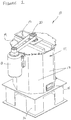
- a particle reduction device 10 is illustrated in the drawings.
- the device specifically illustrated is a multistage gravitational flow particle reduction device operating as a gyroscopic centrifuge which rapidly and continuously reduces the particle size of material fed into the device through at least two stages to output material having a particle size significantly smaller compared to the size of the material introduced.
- Material that may be fed through the device 10 includes any type of material having particles that may be reduced in size by shredding, grinding, beating, crushing, and the like. Some examples include fibrous material such as paper and other cellulose material, wood, grain, plastics and glass. For the purpose of the following description reference will be made largely to paper fibre.
- the particle reduction device 10 is able to replace two or more known particle reduction devices usually used in tandem or to at least provide a faster particle reduction process.
- particle reduction device 10 comprises an enclosed housing 12, the housing having side walls 13 forming a nonagon shaped housing. Housing 12 is supported on base platform 14. A feed inlet 15 at the top of housing 12 receives material to be processed, while processed material exits through an outlet 16 located a lower end of side walls 13. Material is processed in a flow chamber 22 inside the housing 12.
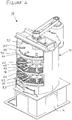
- a motor 18 attached to the side of the housing 12 drives, by way of a belt 19, a central shaft 20 vertically positioned through the interior of the housing, as illustrated in Figures 3 and 4 .
- Figures 3 and 4 illustrate inside the housing and show a flow chamber 22 having three vertically spaced particle reduction stages 30, 40, 50.
- Particulate matter introduced into the flow chamber 22 through feed inlet 15 is reduced in size at each stage by way of impacting/grinding the material using beaters or blades having blunt edges.
- Particulate matter that has been sufficiently reduced in size by one stage passes down the device through to the next stage to be further reduced in size. Once the matter has passed through all stages it exits through outlets 16 with a final reduced particle size.
- the particle reduction stages 30, 40, 50 are each defined by a beater assembly and a separation platform.
- the beater assembly at each stage comprises a number of beaters 32, 42, 52 attached to a beater plate 33, 43, 53 that is mounted onto the central shaft 20 to rotate about shaft 20.
- the beater assembly comprises a beater plate 33 having a large diameter covering a large proportion of the housing's cross-sectional area.
- the beater plate 33 supports eight short beaters 32, although the number of beaters may vary depending on requirement.
- Beater plate 33 and beaters 32 rotate close to and spaced above the separation platform, which at the first stage is a shelf 34 having a large variable aperture 35. Shelf 34 extends across the entire interior of housing.
- Aperture 35 has substantially the same diameter as beater plate 33 such that particulate material flows from the first stage to the second stage through the gap 36 between beater plate 33 and shelf 34.
- beaters 32 cut and impact into the circulating particulate material reducing the size of particles in preparation for the next stage.
- whole sheets of newspaper introduced into the particulate reduction device is impacted at the first stage 30 preferably reducing the newspaper to about 10 cm 2 , although this size can vary depending on the size of gap 36.
- the second particle separation stage 40 is shown in Figure 5(b) and is located below the first stage 30 and approximately midway down the housing interior.
- the beater assembly at the second stage comprises eight long beaters 42 supported on a beater plate 43 mounted to shaft 20.
- Second beater plate 43 is smaller in diameter than the beater plate 33 of the first stage with long beaters 42 extending further out from the second beater plate 43 than the short beaters 33 of the first stage.
- Long beaters 42 extend close to the interior wall of housing 12.
- the separation platform at the second stage is a first perforated screen located directly beneath the beater assembly.
- the screen 45 extends across the whole interior of the housing and contains specifically and uniformly sized perforations 46 such that particulate matter can only pass through the perforations in order to reach the next stage and to exit. It follows that material flowing through the device can only pass through the first screen 45 if the material particles are the same size or smaller than the size of the perforations.
- Long beaters 42 rotate about central shaft 20 impacting, cutting and grinding particulate material from the first stage down to a size that will allow the particles to pass through the perforations in the first screen 45. Together with the circumferential movement of the particles around the housing interior, the beaters break or beat against the particulate material causing the material to grind and move over the screen surface and abrade until the material passes through the perforations.
- the particulate material Having passed through the first screen in the second stage of particle reduction, the particulate material continues to flow down, under gravitational flow, centrifugal flow and/or suction, to the third stage 50, which in the embodiment shown is the final stage of particle reduction.
- the third stage 50 is similar to the second stage 40 in that it includes a beater assembly with long beaters 52 supported on a small beater plate 53 adapted to rotate above a second screen 55.
- Second screen 55 constitutes the separation platform in the third stage and extends across the interior of the housing.
- Second screen 55 contains a number of small perforations 56 that are smaller in size than the larger perforations 46 in the first screen.
- the size of particles flowing through the third stage 50 is reduced by long beaters 52 and their passage regulated by the smaller perforations.
- the particles After passing through the third stage 50 the particles are at their desired reduced size and are carried through to the outlets where the particulate material is evacuated.
- Figure 6 illustrates the reduction process of particulate material 25 down through the three stages.
- Three particle reduction stages are described herein, although it is understood that the principle of the device may be incorporated into a device with only two stages, of which only one need incorporate a beater/perforated screen assembly. Similarly, more than three stages may be used in a device where it may be appropriate to spread the particle reduction process over more screen passes.
- the size of the perforations 46, 56 is chosen dependent on the size of material introduced into the device and on the desired size exiting the device. For instance, with paper in the form of newspaper, the particle reduction device will reduce whole newspaper into small fibrous matter.
- the third stage flow rate of material should be of a higher capacity than that of the second stage. This may be achieved by having a greater number of small perforations 56 in the second screen 55 having a collective area greater than the collective area of the perforations 46 in the first screen.
- the multi-faceted nature of the housing walls, and hence housing interior, promotes particle circulation throughout the flow chamber 22 to avoid the build up of particulate material that may occur on the circumference of a cylindrical chamber.
- Particle reduction device 10 operates under gravitational flow, the rotation of the beater assemblies causing centrifugal circulation to encourage flow. Particle flow through the flow chamber may be fan assisted to draw particles down through the device.
- the particle reduction stages are described as being one above the other. It is however feasible that the reduction stages be aligned horizontally, or otherwise, provided flow assistance such as by fans are used to assist in guiding the particle flow path.
- the particle reduction device 10 provides an efficient means for reducing the size of particles by using a single device. Because no other device is required in tandem, the process of reducing material to a smaller size with the present device is more energy and cost efficient, and fewer parts leads to less machine maintenance.
Landscapes
- Engineering & Computer Science (AREA)
- Food Science & Technology (AREA)
- Crushing And Pulverization Processes (AREA)
- Disintegrating Or Milling (AREA)
Claims (16)
- Dispositif de réduction de particule de papier comprenant :un boîtier (12) contenant une entrée (15) pour recevoir un matériau dans une chambre d'écoulement, au moins deux étages de réduction de particule espacés de manière verticale et adjacente (30, 40, 50) à travers lesquels le matériau s'écoule d'un étage à l'autre pour réduire la taille de particule du matériau, et une sortie (16) pour délivrer en sortie un matériau traité avec une taille de particule réduite ; chaque étage de réduction de particule ayant un élément percutant (32, 42, 52) qui tourne autour d'un arbre central (20) pour percuter le matériau en des particules plus petites ;dans lequel au moins l'un des étages a un tamis (45, 55) situé en aval de l'élément percutant, le tamis ayant des perforations à travers lesquelles des particules d'une taille suffisamment petite peuvent passer ;caractérisé en ce que l'élément percutant comprend des batteurs allongés (32, 42, 52) supportés sur et s'étendant radialement depuis une plaque de batteur (33, 43, 53) montée sur l'arbre central ; etdans lequel le boîtier a une paroi intérieure à plusieurs facettes (13).
- Dispositif de réduction de particule revendiqué dans la revendication 1, dans lequel les étages de réduction de particule sont espacés de manière verticale les uns au-dessus des autres et le matériau est transporté à travers les étages par écoulement gravitationnel.
- Dispositif de réduction de particule revendiqué dans la revendication 1 ou la revendication 2, caractérisé en ce qu'un ventilateur est prévu pour induire un écoulement d'air et aider ou essentiellement attirer le matériau à travers les étages de réduction de particule.
- Dispositif de réduction de particule revendiqué dans la revendication 1, caractérisé en ce que le tamis perforé est situé dans le dernier étage de réduction de particule avant la sortie.
- Dispositif de réduction de particule revendiqué dans la revendication 1, caractérisé en ce qu'il y a au moins trois étages de réduction de particule, les deux derniers étages ayant tous deux un tamis perforé où la taille des perforations dans le tamis du troisième étage est plus petite que les perforations dans le tamis du deuxième étage.
- Dispositif de réduction de particule revendiqué dans la revendication 5, caractérisé en ce que les perforations dans les tamis produisent une zone d'écoulement totale telle que le débit de matériau à travers un étage est inférieur au débit de matériau à travers l'étage suivant.
- Dispositif de réduction de particule revendiqué dans l'une quelconque des revendications précédentes, caractérisé en ce qu'au niveau d'un premier étage l'élément percutant est situé au-dessus d'un plateau (34) contenant une grande ouverture (35), l'élément percutant tournant à proximité de la circonférence de l'ouverture sur le plateau.
- Dispositif de réduction de particule revendiqué dans la revendication 7, caractérisé en ce que l'élément percutant au niveau du premier étage est un rotor monobloc réglé pour tourner autour de l'arbre central et ayant des batteurs courts disposés autour de la circonférence du rotor monobloc.
- Dispositif de réduction de particule revendiqué dans l'une quelconque des revendications précédentes, caractérisée en ce qu'au niveau des étages ayant un tamis perforé l'élément percutant comprend des batteurs allongés fixés à une plaque de batteur qui tourne autour de l'arbre central.
- Dispositif de réduction de particule revendiqué dans la revendication 9, caractérisé en ce que chaque plaque de batteur supporte entre quatre et dix batteurs.
- Dispositif de réduction de particule revendiqué dans l'une quelconque des revendications précédentes, caractérisé en ce que les batteurs allongés s'étendent à proximité de la paroi intérieure du boîtier (12).
- Procédé de réduction de la taille de particule d'un matériau de papier comportant :le fait d'introduire un matériau dans un dispositif de réduction de particule comprenant au moins deux étages espacés de manière verticale et adjacente (30, 40, 50) pour réduire la taille de particule ;le fait de percuter avec un élément percutant (32, 42, 52) au niveau de chaque étage à mesure que le matériau s'écoule à travers le dispositif pour réduire la taille de particule du matériau au niveau de chaque étage, l'élément percutant comprenant des batteurs allongés (32, 42, 52) supportés sur, et s'étendant radialement depuis, une plaque de batteur (33, 43, 53) montée sur un arbre central ;et ce par quoi au moins l'un des étages percute le matériau dans un intérieur de boîtier à plusieurs facettes (13) jusqu'à ce que le matériel ait une taille suffisamment petite pour passer à travers un tamis perforé (45, 55) situé en aval de l'élément percutant ; etle fait de transporter le matériau avec une taille de particules réduite hors du dispositif.
- Procédé de réduction de la taille de particule d'un matériau tel que revendiqué dans la revendication 12, comportant le fait de transporter verticalement le matériau d'un étage de réduction de particule à un autre sous écoulement gravitationnel.
- Procédé de réduction de la taille de particule d'un matériau tel que revendiqué dans la revendication 10, caractérisé par le fait d'utiliser de l'air induit pour aider à transporter le matériau à travers les étages.
- Procédé de réduction de la taille de particule d'un matériau tel que revendiqué dans l'une des revendications 12 à 14, caractérisé par le fait de transporter le matériau à travers trois étages de réduction de particule ce par quoi la taille de particule du matériau est réduite à chaque étage.
- Procédé de réduction de la taille de particule d'un matériau tel que revendiqué dans la revendication 15, caractérisé par le fait de percuter le matériau au niveau des deux derniers étages jusqu'à ce qu'il ait une taille suffisamment petite pour passer à travers des tamis perforés au niveau des deux derniers étages, les perforations du dernier étage étant plus petites que les perforations de l'avant-dernier étage.
Applications Claiming Priority (2)
| Application Number | Priority Date | Filing Date | Title |
|---|---|---|---|
| AU2007902223A AU2007902223A0 (en) | 2007-04-27 | Particle reduction device | |
| PCT/AU2008/000563 WO2008131477A1 (fr) | 2007-04-27 | 2008-04-22 | Dispositif de réduction de particule |
Publications (3)
| Publication Number | Publication Date |
|---|---|
| EP2155397A1 EP2155397A1 (fr) | 2010-02-24 |
| EP2155397A4 EP2155397A4 (fr) | 2014-03-05 |
| EP2155397B1 true EP2155397B1 (fr) | 2019-02-06 |
Family
ID=39925095
Family Applications (1)
| Application Number | Title | Priority Date | Filing Date |
|---|---|---|---|
| EP08733390.2A Active EP2155397B1 (fr) | 2007-04-27 | 2008-04-22 | Dispositif de réduction de particule |
Country Status (7)
| Country | Link |
|---|---|
| US (1) | US8267337B2 (fr) |
| EP (1) | EP2155397B1 (fr) |
| AU (1) | AU2008243691B2 (fr) |
| CA (1) | CA2685183C (fr) |
| ES (1) | ES2722178T3 (fr) |
| NZ (1) | NZ579713A (fr) |
| WO (1) | WO2008131477A1 (fr) |
Families Citing this family (42)
| Publication number | Priority date | Publication date | Assignee | Title |
|---|---|---|---|---|
| US8662429B2 (en) * | 2012-01-17 | 2014-03-04 | Fellowes, Inc. | Modular document destruction system |
| JP5847206B2 (ja) * | 2012-01-30 | 2016-01-20 | 有限会社大東土木 | 再生骨材の製造方法及びこの方法により得られる再生骨材 |
| RU2487758C1 (ru) * | 2012-02-09 | 2013-07-20 | Общество с ограниченной ответственностью "НПП Профиль-Т" (ООО "НПП Профиль-Т") | Гироскопический измельчитель с загрузкой породы через полый вал вращения рабочей площадки |
| US9751087B2 (en) * | 2012-09-20 | 2017-09-05 | Gary L. Watts | Comminution mill with cable impact arms |
| US20160045919A1 (en) * | 2012-11-07 | 2016-02-18 | Heritage Environmental Services Inc. | Vertical shaft impactor |
| GB2515119A (en) * | 2013-06-14 | 2014-12-17 | Global Advanced Recycling Company Ltd | Method and rotary processor for processing waste into fertilizer |
| FR3017872B1 (fr) * | 2014-02-21 | 2016-05-20 | Coatex Sas | Utilisation de copolymeres de styrene et d'anhydride maleique pour preparer des particules de matiere minerale |
| US10799873B2 (en) * | 2015-02-12 | 2020-10-13 | Energy Creates Energy Llc | Nautiloid shaped fan housing for a comminution mill |
| US10500591B2 (en) * | 2015-09-02 | 2019-12-10 | Air Products And Chemicals, Inc. | System and method for the preparation of a feedstock |
| US11298703B2 (en) * | 2016-01-13 | 2022-04-12 | Torxx Kinetic Pulverizer Limited | Modular pulverizer |
| US11440021B2 (en) | 2016-01-15 | 2022-09-13 | Torxx Kinetic Pulverizer Limited | Pulverizer system |
| US20190001336A1 (en) | 2016-01-15 | 2019-01-03 | Jaroslaw Lutoslawski | Centrifugal Pulverizing Mill |
| US12383910B2 (en) | 2016-01-15 | 2025-08-12 | Torxx Kinetic Pulverizer Limited | Pulverizer system |
| CN106040415A (zh) * | 2016-07-18 | 2016-10-26 | 山东省阳信万信生物制品开发有限公司 | 大颗粒破碎分级装置 |
| CN108080099B (zh) * | 2016-11-23 | 2023-08-22 | 广州正晟科技有限公司 | 污泥破碎机及其破碎方法 |
| CN108080098B (zh) * | 2016-11-23 | 2023-08-22 | 广州正晟科技有限公司 | 用于污泥破碎机的破碎组件及其构造方法 |
| WO2018152776A1 (fr) * | 2017-02-24 | 2018-08-30 | 深圳市玖创科技有限公司 | Dispositif de broyage, de criblage et d'alimentation de matériau d'électrode négative de batterie |
| CN106861837A (zh) * | 2017-02-24 | 2017-06-20 | 深圳市玖创科技有限公司 | 一种电池负极材料破碎筛分进料设备 |
| CN107159407A (zh) * | 2017-06-09 | 2017-09-15 | 安徽机电职业技术学院 | 一种物料加工专用的粉碎筛选机械 |
| CN107116653B (zh) * | 2017-06-24 | 2019-04-12 | 日照市澳思柏恩装饰材料有限公司 | 一种家具制造用刨花板材原材料自动化加工设备 |
| CN109248751B (zh) * | 2017-07-14 | 2021-09-17 | 广州正晟科技有限公司 | 污泥破碎机以及利用其破碎污泥的方法 |
| CN107684965B (zh) * | 2017-10-17 | 2019-11-19 | 玉环县双法铜业有限公司 | 一种用于生物垃圾回收的搅拌粉碎装置 |
| US11369973B2 (en) * | 2017-11-14 | 2022-06-28 | Eco Tec Mineria Corp. | Method and device for milling and separation of solids and granular materials including metal containing materials as well as phytogenic materials with high level of silicon in a controlled airflow |
| CN108405123A (zh) * | 2018-02-07 | 2018-08-17 | 常成友 | 用于建筑施工的设备 |
| CN108311236A (zh) * | 2018-03-30 | 2018-07-24 | 安吉艺科装饰材料科技有限公司 | 一种具有筛分功能的原料粉碎装置 |
| CN117019310A (zh) | 2018-07-12 | 2023-11-10 | 托尔克斯动力粉碎机有限公司 | 粉碎机系统和粉碎材料的方法 |
| CN109530025A (zh) * | 2018-11-20 | 2019-03-29 | 盐城哈力动力传动及智能装备产业研究院有限公司 | 一种齿轮碾压装置 |
| IT201900002795A1 (it) * | 2019-02-27 | 2020-08-27 | Claudio Bano | Frantumatore perfezionato |
| CN110314746A (zh) * | 2019-08-08 | 2019-10-11 | 黄基华 | 一种化工粉料的粉碎筛选装置 |
| CN110694757A (zh) * | 2019-11-14 | 2020-01-17 | 徐州给力磁业有限公司 | 一种稀土破碎装置 |
| CN110882818A (zh) * | 2019-12-26 | 2020-03-17 | 丁志鹏 | 一种大处理量高破碎比立式冲击破碎机 |
| PL3871776T3 (pl) | 2020-02-25 | 2022-11-21 | AUMUND Fördertechnik GmbH | Urządzenie do przetwarzania mieszaniny materiałowej składającej się z paliwa zastępczego i materiału zanieczyszczającego |
| CN112090511A (zh) * | 2020-08-20 | 2020-12-18 | 枣庄鑫金山智能装备有限公司 | 一种高效节能砂石同出成套装置 |
| CN112058399A (zh) * | 2020-08-28 | 2020-12-11 | 湖南贝恩叮当猫婴童用品有限公司 | 一种用于拉拉裤生产的粉碎装置 |
| CN112677315B (zh) * | 2020-12-24 | 2022-01-14 | 日照市政装配式城市设施有限公司 | 一种混凝土制备方法 |
| WO2022266766A1 (fr) | 2021-06-25 | 2022-12-29 | Torxx Kinetic Pulverizer Limited | Procédé de traitement d'un écoulement de fines issu d'installations de traitement de déchets |
| CN113787000B (zh) * | 2021-09-17 | 2022-12-13 | 仁新实业发展(信阳)有限公司 | 一种制砂整形机及制砂方法 |
| CN115487918B (zh) * | 2022-10-20 | 2024-02-20 | 郑杰 | 一种医用淀粉研磨自动筛选装置 |
| CN115609780B (zh) * | 2022-12-21 | 2023-03-10 | 苏州优可发新材料科技有限公司 | 一种ptfe膜生产预处理装置 |
| CN117414907B (zh) * | 2023-12-19 | 2024-03-26 | 山西省长治经坊煤业有限公司 | 一种煤矿开采用物料收集处理装置 |
| CN118371311B (zh) * | 2024-06-25 | 2024-09-17 | 福建拓天生物科技有限公司 | 一种食用菌切片及打粉设备 |
| CN118558449B (zh) * | 2024-08-02 | 2024-10-18 | 立达超微科技(安徽青阳)有限公司 | 一种多级筛分碳酸钙用装置 |
Family Cites Families (15)
| Publication number | Priority date | Publication date | Assignee | Title |
|---|---|---|---|---|
| US744382A (en) * | 1902-11-03 | 1903-11-17 | Harry Moor | Pulverizer. |
| US1527818A (en) * | 1924-11-07 | 1925-02-24 | Schutzo Neill Company | Grinding mill |
| US2639747A (en) * | 1948-04-15 | 1953-05-26 | Burn Lewis | Rotary granulating machine |
| GB1261709A (en) * | 1968-07-17 | 1972-01-26 | Nicholas Pora | Two stage hammer mill |
| US4151794A (en) * | 1978-05-24 | 1979-05-01 | Burkett Albert L | Apparatus for treating organic materials |
| DE3048068C2 (de) | 1980-12-19 | 1982-12-02 | m & a Hommel GmbH, 5603 Wülfrath | Gerät zum Feinzerkleinern von Bäckereiprodukten |
| JPS58193109A (ja) | 1982-05-06 | 1983-11-10 | Sumitomo Chem Co Ltd | 含水高分子量水溶性重合体の粗砕方法 |
| US4886216A (en) * | 1988-03-08 | 1989-12-12 | Goble Ralph W | Mill for pulverizing rock and other material |
| US5680994A (en) * | 1989-07-10 | 1997-10-28 | Wastenot International Ltd. | Mill for grinding garbage or the like |
| US5192029A (en) * | 1990-02-05 | 1993-03-09 | Universal Entech | Gyroscopic centrifuge and mill apparatus and method of use for treatment of solid waste products |
| BR9507351A (pt) | 1994-04-11 | 1997-09-23 | Mount Isa Mines | Moinho de triturar |
| JPH08309214A (ja) * | 1995-05-22 | 1996-11-26 | Ishikawajima Harima Heavy Ind Co Ltd | 竪型破砕機 |
| US5740971A (en) | 1995-11-17 | 1998-04-21 | Hsu; Wu-Heng | Apparatus for recycling synthetic leather |
| EP1015120B1 (fr) * | 1997-07-18 | 2004-03-24 | C.A. Arnold & Associates, Inc. | Pulverisation de materiaux en vue de former des particules de petite taille |
| US6179231B1 (en) * | 1999-07-12 | 2001-01-30 | Ernest Csendes | Method and apparatus for comminuting solid particles |
-
2008
- 2008-04-22 NZ NZ579713A patent/NZ579713A/en not_active IP Right Cessation
- 2008-04-22 CA CA2685183A patent/CA2685183C/fr active Active
- 2008-04-22 US US12/596,877 patent/US8267337B2/en active Active
- 2008-04-22 WO PCT/AU2008/000563 patent/WO2008131477A1/fr not_active Ceased
- 2008-04-22 ES ES08733390T patent/ES2722178T3/es active Active
- 2008-04-22 AU AU2008243691A patent/AU2008243691B2/en not_active Ceased
- 2008-04-22 EP EP08733390.2A patent/EP2155397B1/fr active Active
Non-Patent Citations (1)
| Title |
|---|
| None * |
Also Published As
| Publication number | Publication date |
|---|---|
| EP2155397A1 (fr) | 2010-02-24 |
| EP2155397A4 (fr) | 2014-03-05 |
| AU2008243691A1 (en) | 2008-11-06 |
| US8267337B2 (en) | 2012-09-18 |
| AU2008243691B2 (en) | 2012-11-15 |
| US20100140384A1 (en) | 2010-06-10 |
| ES2722178T3 (es) | 2019-08-07 |
| CA2685183C (fr) | 2015-01-20 |
| CA2685183A1 (fr) | 2008-11-06 |
| NZ579713A (en) | 2012-07-27 |
| WO2008131477A1 (fr) | 2008-11-06 |
Similar Documents
| Publication | Publication Date | Title |
|---|---|---|
| EP2155397B1 (fr) | Dispositif de réduction de particule | |
| US5188298A (en) | Method and apparatus for fiberizing | |
| CA2976406C (fr) | Boitier de ventilateur en forme de nautiloide pour un broyeur de comminution | |
| USRE35118E (en) | Method and apparatus for fiberizing and cellulosic product thereof | |
| JP2020075235A (ja) | 撹拌ボールミル及び撹拌ボールミルの作動方法 | |
| CN101664709B (zh) | 粉碎装置 | |
| CN101652191B (zh) | 用于筛选给料的装置及方法 | |
| US4228964A (en) | Apparatus for processing cellulose insulation | |
| US5769332A (en) | Efficient production of landplaster by collecting and classsifying gypsum fines | |
| JP3264891B2 (ja) | 循環式粉砕装置 | |
| EP0558572B1 (fr) | Separateur double servant a trier des matieres particulaires | |
| CN106000542B (zh) | 一种餐厨垃圾分选破碎一体机及方法 | |
| JP3051981B1 (ja) | 繊維含有材料の縦型粗粉砕装置及びその刃物構造 | |
| RU2263540C2 (ru) | Вальцовая мельница для измельчения и сортировки сыпучих материалов | |
| KR101108513B1 (ko) | 수직식 패각 분쇄기 | |
| US3556420A (en) | Apparatus for comminuting compost | |
| RU2540549C1 (ru) | Установка для измельчения волокнистых материалов | |
| JP3562213B2 (ja) | 竪型粉砕機 | |
| JP4441274B2 (ja) | 粉砕分別システム | |
| RU2193839C2 (ru) | Двухступенчатый измельчитель кормов | |
| JPH0318935B2 (fr) | ||
| KR200407426Y1 (ko) | 파쇄 선별기 | |
| KR20240162781A (ko) | 광물 분쇄기 | |
| JP2026007428A (ja) | 拡散装置、拡散方法および生産装置 | |
| SU1722832A1 (ru) | Мельница дл древесных материалов |
Legal Events
| Date | Code | Title | Description |
|---|---|---|---|
| PUAI | Public reference made under article 153(3) epc to a published international application that has entered the european phase |
Free format text: ORIGINAL CODE: 0009012 |
|
| 17P | Request for examination filed |
Effective date: 20091127 |
|
| AK | Designated contracting states |
Kind code of ref document: A1 Designated state(s): AT BE BG CH CY CZ DE DK EE ES FI FR GB GR HR HU IE IS IT LI LT LU LV MC MT NL NO PL PT RO SE SI SK TR |
|
| AX | Request for extension of the european patent |
Extension state: AL BA MK RS |
|
| DAX | Request for extension of the european patent (deleted) | ||
| A4 | Supplementary search report drawn up and despatched |
Effective date: 20140203 |
|
| RIC1 | Information provided on ipc code assigned before grant |
Ipc: B02C 13/288 20060101ALN20140128BHEP Ipc: B02C 23/14 20060101ALI20140128BHEP Ipc: B02C 23/10 20060101ALI20140128BHEP Ipc: B02C 23/08 20060101ALI20140128BHEP Ipc: B02C 13/284 20060101ALI20140128BHEP Ipc: B02C 13/18 20060101AFI20140128BHEP |
|
| REG | Reference to a national code |
Ref country code: DE Ref legal event code: R079 Ref document number: 602008058945 Country of ref document: DE Free format text: PREVIOUS MAIN CLASS: B02C0023080000 Ipc: B02C0013180000 |
|
| RIC1 | Information provided on ipc code assigned before grant |
Ipc: B02C 23/08 20060101ALI20180703BHEP Ipc: B02C 23/14 20060101ALI20180703BHEP Ipc: B02C 13/18 20060101AFI20180703BHEP Ipc: B02C 23/10 20060101ALI20180703BHEP Ipc: B02C 13/288 20060101ALN20180703BHEP Ipc: B02C 13/284 20060101ALI20180703BHEP |
|
| GRAP | Despatch of communication of intention to grant a patent |
Free format text: ORIGINAL CODE: EPIDOSNIGR1 |
|
| STAA | Information on the status of an ep patent application or granted ep patent |
Free format text: STATUS: GRANT OF PATENT IS INTENDED |
|
| RIC1 | Information provided on ipc code assigned before grant |
Ipc: B02C 13/288 20060101ALN20180803BHEP Ipc: B02C 13/284 20060101ALI20180803BHEP Ipc: B02C 23/14 20060101ALI20180803BHEP Ipc: B02C 13/18 20060101AFI20180803BHEP Ipc: B02C 23/10 20060101ALI20180803BHEP Ipc: B02C 23/08 20060101ALI20180803BHEP |
|
| INTG | Intention to grant announced |
Effective date: 20180823 |
|
| RIN1 | Information on inventor provided before grant (corrected) |
Inventor name: WEBB, DONALD, BARRY |
|
| GRAS | Grant fee paid |
Free format text: ORIGINAL CODE: EPIDOSNIGR3 |
|
| GRAA | (expected) grant |
Free format text: ORIGINAL CODE: 0009210 |
|
| STAA | Information on the status of an ep patent application or granted ep patent |
Free format text: STATUS: THE PATENT HAS BEEN GRANTED |
|
| AK | Designated contracting states |
Kind code of ref document: B1 Designated state(s): AT BE BG CH CY CZ DE DK EE ES FI FR GB GR HR HU IE IS IT LI LT LU LV MC MT NL NO PL PT RO SE SI SK TR |
|
| REG | Reference to a national code |
Ref country code: GB Ref legal event code: FG4D |
|
| REG | Reference to a national code |
Ref country code: CH Ref legal event code: EP Ref country code: AT Ref legal event code: REF Ref document number: 1094525 Country of ref document: AT Kind code of ref document: T Effective date: 20190215 |
|
| REG | Reference to a national code |
Ref country code: DE Ref legal event code: R096 Ref document number: 602008058945 Country of ref document: DE |
|
| REG | Reference to a national code |
Ref country code: IE Ref legal event code: FG4D |
|
| REG | Reference to a national code |
Ref country code: NL Ref legal event code: FP |
|
| REG | Reference to a national code |
Ref country code: LT Ref legal event code: MG4D |
|
| PG25 | Lapsed in a contracting state [announced via postgrant information from national office to epo] |
Ref country code: PT Free format text: LAPSE BECAUSE OF FAILURE TO SUBMIT A TRANSLATION OF THE DESCRIPTION OR TO PAY THE FEE WITHIN THE PRESCRIBED TIME-LIMIT Effective date: 20190606 Ref country code: SE Free format text: LAPSE BECAUSE OF FAILURE TO SUBMIT A TRANSLATION OF THE DESCRIPTION OR TO PAY THE FEE WITHIN THE PRESCRIBED TIME-LIMIT Effective date: 20190206 Ref country code: NO Free format text: LAPSE BECAUSE OF FAILURE TO SUBMIT A TRANSLATION OF THE DESCRIPTION OR TO PAY THE FEE WITHIN THE PRESCRIBED TIME-LIMIT Effective date: 20190506 Ref country code: FI Free format text: LAPSE BECAUSE OF FAILURE TO SUBMIT A TRANSLATION OF THE DESCRIPTION OR TO PAY THE FEE WITHIN THE PRESCRIBED TIME-LIMIT Effective date: 20190206 Ref country code: LT Free format text: LAPSE BECAUSE OF FAILURE TO SUBMIT A TRANSLATION OF THE DESCRIPTION OR TO PAY THE FEE WITHIN THE PRESCRIBED TIME-LIMIT Effective date: 20190206 |
|
| REG | Reference to a national code |
Ref country code: ES Ref legal event code: FG2A Ref document number: 2722178 Country of ref document: ES Kind code of ref document: T3 Effective date: 20190807 |
|
| REG | Reference to a national code |
Ref country code: AT Ref legal event code: MK05 Ref document number: 1094525 Country of ref document: AT Kind code of ref document: T Effective date: 20190206 |
|
| PG25 | Lapsed in a contracting state [announced via postgrant information from national office to epo] |
Ref country code: GR Free format text: LAPSE BECAUSE OF FAILURE TO SUBMIT A TRANSLATION OF THE DESCRIPTION OR TO PAY THE FEE WITHIN THE PRESCRIBED TIME-LIMIT Effective date: 20190507 Ref country code: BG Free format text: LAPSE BECAUSE OF FAILURE TO SUBMIT A TRANSLATION OF THE DESCRIPTION OR TO PAY THE FEE WITHIN THE PRESCRIBED TIME-LIMIT Effective date: 20190506 Ref country code: HR Free format text: LAPSE BECAUSE OF FAILURE TO SUBMIT A TRANSLATION OF THE DESCRIPTION OR TO PAY THE FEE WITHIN THE PRESCRIBED TIME-LIMIT Effective date: 20190206 Ref country code: IS Free format text: LAPSE BECAUSE OF FAILURE TO SUBMIT A TRANSLATION OF THE DESCRIPTION OR TO PAY THE FEE WITHIN THE PRESCRIBED TIME-LIMIT Effective date: 20190606 Ref country code: LV Free format text: LAPSE BECAUSE OF FAILURE TO SUBMIT A TRANSLATION OF THE DESCRIPTION OR TO PAY THE FEE WITHIN THE PRESCRIBED TIME-LIMIT Effective date: 20190206 |
|
| PG25 | Lapsed in a contracting state [announced via postgrant information from national office to epo] |
Ref country code: RO Free format text: LAPSE BECAUSE OF FAILURE TO SUBMIT A TRANSLATION OF THE DESCRIPTION OR TO PAY THE FEE WITHIN THE PRESCRIBED TIME-LIMIT Effective date: 20190206 Ref country code: SK Free format text: LAPSE BECAUSE OF FAILURE TO SUBMIT A TRANSLATION OF THE DESCRIPTION OR TO PAY THE FEE WITHIN THE PRESCRIBED TIME-LIMIT Effective date: 20190206 Ref country code: EE Free format text: LAPSE BECAUSE OF FAILURE TO SUBMIT A TRANSLATION OF THE DESCRIPTION OR TO PAY THE FEE WITHIN THE PRESCRIBED TIME-LIMIT Effective date: 20190206 Ref country code: DK Free format text: LAPSE BECAUSE OF FAILURE TO SUBMIT A TRANSLATION OF THE DESCRIPTION OR TO PAY THE FEE WITHIN THE PRESCRIBED TIME-LIMIT Effective date: 20190206 Ref country code: CZ Free format text: LAPSE BECAUSE OF FAILURE TO SUBMIT A TRANSLATION OF THE DESCRIPTION OR TO PAY THE FEE WITHIN THE PRESCRIBED TIME-LIMIT Effective date: 20190206 |
|
| REG | Reference to a national code |
Ref country code: DE Ref legal event code: R097 Ref document number: 602008058945 Country of ref document: DE |
|
| PG25 | Lapsed in a contracting state [announced via postgrant information from national office to epo] |
Ref country code: PL Free format text: LAPSE BECAUSE OF FAILURE TO SUBMIT A TRANSLATION OF THE DESCRIPTION OR TO PAY THE FEE WITHIN THE PRESCRIBED TIME-LIMIT Effective date: 20190206 |
|
| REG | Reference to a national code |
Ref country code: CH Ref legal event code: PL |
|
| PLBE | No opposition filed within time limit |
Free format text: ORIGINAL CODE: 0009261 |
|
| STAA | Information on the status of an ep patent application or granted ep patent |
Free format text: STATUS: NO OPPOSITION FILED WITHIN TIME LIMIT |
|
| REG | Reference to a national code |
Ref country code: BE Ref legal event code: MM Effective date: 20190430 |
|
| PG25 | Lapsed in a contracting state [announced via postgrant information from national office to epo] |
Ref country code: LU Free format text: LAPSE BECAUSE OF NON-PAYMENT OF DUE FEES Effective date: 20190422 Ref country code: AT Free format text: LAPSE BECAUSE OF FAILURE TO SUBMIT A TRANSLATION OF THE DESCRIPTION OR TO PAY THE FEE WITHIN THE PRESCRIBED TIME-LIMIT Effective date: 20190206 Ref country code: MC Free format text: LAPSE BECAUSE OF FAILURE TO SUBMIT A TRANSLATION OF THE DESCRIPTION OR TO PAY THE FEE WITHIN THE PRESCRIBED TIME-LIMIT Effective date: 20190206 |
|
| 26N | No opposition filed |
Effective date: 20191107 |
|
| PG25 | Lapsed in a contracting state [announced via postgrant information from national office to epo] |
Ref country code: CH Free format text: LAPSE BECAUSE OF NON-PAYMENT OF DUE FEES Effective date: 20190430 Ref country code: LI Free format text: LAPSE BECAUSE OF NON-PAYMENT OF DUE FEES Effective date: 20190430 |
|
| PG25 | Lapsed in a contracting state [announced via postgrant information from national office to epo] |
Ref country code: BE Free format text: LAPSE BECAUSE OF NON-PAYMENT OF DUE FEES Effective date: 20190430 Ref country code: SI Free format text: LAPSE BECAUSE OF FAILURE TO SUBMIT A TRANSLATION OF THE DESCRIPTION OR TO PAY THE FEE WITHIN THE PRESCRIBED TIME-LIMIT Effective date: 20190206 |
|
| PG25 | Lapsed in a contracting state [announced via postgrant information from national office to epo] |
Ref country code: TR Free format text: LAPSE BECAUSE OF FAILURE TO SUBMIT A TRANSLATION OF THE DESCRIPTION OR TO PAY THE FEE WITHIN THE PRESCRIBED TIME-LIMIT Effective date: 20190206 |
|
| PG25 | Lapsed in a contracting state [announced via postgrant information from national office to epo] |
Ref country code: IE Free format text: LAPSE BECAUSE OF NON-PAYMENT OF DUE FEES Effective date: 20190422 |
|
| PG25 | Lapsed in a contracting state [announced via postgrant information from national office to epo] |
Ref country code: CY Free format text: LAPSE BECAUSE OF FAILURE TO SUBMIT A TRANSLATION OF THE DESCRIPTION OR TO PAY THE FEE WITHIN THE PRESCRIBED TIME-LIMIT Effective date: 20190206 |
|
| PG25 | Lapsed in a contracting state [announced via postgrant information from national office to epo] |
Ref country code: MT Free format text: LAPSE BECAUSE OF FAILURE TO SUBMIT A TRANSLATION OF THE DESCRIPTION OR TO PAY THE FEE WITHIN THE PRESCRIBED TIME-LIMIT Effective date: 20190206 Ref country code: HU Free format text: LAPSE BECAUSE OF FAILURE TO SUBMIT A TRANSLATION OF THE DESCRIPTION OR TO PAY THE FEE WITHIN THE PRESCRIBED TIME-LIMIT; INVALID AB INITIO Effective date: 20080422 |
|
| PGFP | Annual fee paid to national office [announced via postgrant information from national office to epo] |
Ref country code: NL Payment date: 20240315 Year of fee payment: 17 |
|
| PGFP | Annual fee paid to national office [announced via postgrant information from national office to epo] |
Ref country code: GB Payment date: 20240229 Year of fee payment: 17 |
|
| PGFP | Annual fee paid to national office [announced via postgrant information from national office to epo] |
Ref country code: IT Payment date: 20240313 Year of fee payment: 17 Ref country code: FR Payment date: 20240308 Year of fee payment: 17 |
|
| PGFP | Annual fee paid to national office [announced via postgrant information from national office to epo] |
Ref country code: DE Payment date: 20240306 Year of fee payment: 17 |
|
| PGFP | Annual fee paid to national office [announced via postgrant information from national office to epo] |
Ref country code: ES Payment date: 20240508 Year of fee payment: 17 |
|
| REG | Reference to a national code |
Ref country code: DE Ref legal event code: R119 Ref document number: 602008058945 Country of ref document: DE |
|
| REG | Reference to a national code |
Ref country code: NL Ref legal event code: MM Effective date: 20250501 |
|
| GBPC | Gb: european patent ceased through non-payment of renewal fee |
Effective date: 20250422 |
|
| PG25 | Lapsed in a contracting state [announced via postgrant information from national office to epo] |
Ref country code: DE Free format text: LAPSE BECAUSE OF NON-PAYMENT OF DUE FEES Effective date: 20251104 |
|
| PG25 | Lapsed in a contracting state [announced via postgrant information from national office to epo] |
Ref country code: GB Free format text: LAPSE BECAUSE OF NON-PAYMENT OF DUE FEES Effective date: 20250422 |
|
| PG25 | Lapsed in a contracting state [announced via postgrant information from national office to epo] |
Ref country code: NL Free format text: LAPSE BECAUSE OF NON-PAYMENT OF DUE FEES Effective date: 20250501 Ref country code: FR Free format text: LAPSE BECAUSE OF NON-PAYMENT OF DUE FEES Effective date: 20250430 |