EP2154474A2 - Laser device - Google Patents
Laser device Download PDFInfo
- Publication number
- EP2154474A2 EP2154474A2 EP09164736A EP09164736A EP2154474A2 EP 2154474 A2 EP2154474 A2 EP 2154474A2 EP 09164736 A EP09164736 A EP 09164736A EP 09164736 A EP09164736 A EP 09164736A EP 2154474 A2 EP2154474 A2 EP 2154474A2
- Authority
- EP
- European Patent Office
- Prior art keywords
- laser
- unit
- socket
- convex surface
- hollow cylinder
- Prior art date
- Legal status (The legal status is an assumption and is not a legal conclusion. Google has not performed a legal analysis and makes no representation as to the accuracy of the status listed.)
- Granted
Links
- 239000000463 material Substances 0.000 claims description 15
- 238000003780 insertion Methods 0.000 claims description 3
- 230000037431 insertion Effects 0.000 claims description 3
- 238000010276 construction Methods 0.000 description 22
- 230000015572 biosynthetic process Effects 0.000 description 2
- 230000001419 dependent effect Effects 0.000 description 2
- 238000011161 development Methods 0.000 description 2
- 230000018109 developmental process Effects 0.000 description 2
- 230000000694 effects Effects 0.000 description 2
- 241000238633 Odonata Species 0.000 description 1
- 230000003068 static effect Effects 0.000 description 1
Images


Classifications
-
- G—PHYSICS
- G01—MEASURING; TESTING
- G01C—MEASURING DISTANCES, LEVELS OR BEARINGS; SURVEYING; NAVIGATION; GYROSCOPIC INSTRUMENTS; PHOTOGRAMMETRY OR VIDEOGRAMMETRY
- G01C15/00—Surveying instruments or accessories not provided for in groups G01C1/00 - G01C13/00
- G01C15/002—Active optical surveying means
-
- F—MECHANICAL ENGINEERING; LIGHTING; HEATING; WEAPONS; BLASTING
- F16—ENGINEERING ELEMENTS AND UNITS; GENERAL MEASURES FOR PRODUCING AND MAINTAINING EFFECTIVE FUNCTIONING OF MACHINES OR INSTALLATIONS; THERMAL INSULATION IN GENERAL
- F16M—FRAMES, CASINGS OR BEDS OF ENGINES, MACHINES OR APPARATUS, NOT SPECIFIC TO ENGINES, MACHINES OR APPARATUS PROVIDED FOR ELSEWHERE; STANDS; SUPPORTS
- F16M11/00—Stands or trestles as supports for apparatus or articles placed thereon Stands for scientific apparatus such as gravitational force meters
- F16M11/02—Heads
- F16M11/04—Means for attachment of apparatus; Means allowing adjustment of the apparatus relatively to the stand
- F16M11/06—Means for attachment of apparatus; Means allowing adjustment of the apparatus relatively to the stand allowing pivoting
- F16M11/10—Means for attachment of apparatus; Means allowing adjustment of the apparatus relatively to the stand allowing pivoting around a horizontal axis
-
- F—MECHANICAL ENGINEERING; LIGHTING; HEATING; WEAPONS; BLASTING
- F16—ENGINEERING ELEMENTS AND UNITS; GENERAL MEASURES FOR PRODUCING AND MAINTAINING EFFECTIVE FUNCTIONING OF MACHINES OR INSTALLATIONS; THERMAL INSULATION IN GENERAL
- F16M—FRAMES, CASINGS OR BEDS OF ENGINES, MACHINES OR APPARATUS, NOT SPECIFIC TO ENGINES, MACHINES OR APPARATUS PROVIDED FOR ELSEWHERE; STANDS; SUPPORTS
- F16M11/00—Stands or trestles as supports for apparatus or articles placed thereon Stands for scientific apparatus such as gravitational force meters
- F16M11/02—Heads
- F16M11/18—Heads with mechanism for moving the apparatus relatively to the stand
-
- F—MECHANICAL ENGINEERING; LIGHTING; HEATING; WEAPONS; BLASTING
- F16—ENGINEERING ELEMENTS AND UNITS; GENERAL MEASURES FOR PRODUCING AND MAINTAINING EFFECTIVE FUNCTIONING OF MACHINES OR INSTALLATIONS; THERMAL INSULATION IN GENERAL
- F16M—FRAMES, CASINGS OR BEDS OF ENGINES, MACHINES OR APPARATUS, NOT SPECIFIC TO ENGINES, MACHINES OR APPARATUS PROVIDED FOR ELSEWHERE; STANDS; SUPPORTS
- F16M11/00—Stands or trestles as supports for apparatus or articles placed thereon Stands for scientific apparatus such as gravitational force meters
- F16M11/20—Undercarriages with or without wheels
- F16M11/2007—Undercarriages with or without wheels comprising means allowing pivoting adjustment
- F16M11/2021—Undercarriages with or without wheels comprising means allowing pivoting adjustment around a horizontal axis
- F16M11/2028—Undercarriages with or without wheels comprising means allowing pivoting adjustment around a horizontal axis for rolling, i.e. for creating a landscape-portrait rotation
Definitions
- the invention relates to a laser device with a laser unit and a sliding bearing device.
- Laser equipment means a construction laser, as it is used in the construction industry for purposes of defining, transmitting or leveling planes, lines or points.
- static construction lasers such as point or line lasers can also be subsumed under the term laser device, as are rotary construction lasers in which the laser unit emits an at least partially rotating laser beam.
- the invention is used in rotary construction lasers with a laser unit designed as a rotation unit, which is why the following description refers to this type of construction laser for the sake of simplicity. It should be noted, however, that this does not limit the scope of protection and the invention also applies to all other types of construction lasers with an adjustable laser unit.
- Rotary construction laser with a trained as a rotating unit laser unit that emits an at least partially rotating laser beam are used primarily in the construction industry to create and set on walls, ceilings and floors, horizontal, vertical or defined inclined planes.
- Rotary construction lasers are also used, for example in the scanning mode, to define predefined sections of planes or markings (points, lines, etc.) or to generate them as a reference.
- a bearing device for tilting or adjusting the rotation unit of the Rotationsbaulasers must therefore be robust and easily adjustable.
- the rotation unit is substantially adjusted by means of the bearing device.
- a coarse adjustment takes place before the adjustment, for example by an operator. This can be done, for example, by hand with the help of visible from the outside on Rotationsbaulaser attached dragonflies. Subsequently, the operator can initiate an automatic adjustment, in which the rotation unit is finely adjusted (adjusted), for example by means of servomotors and the bearing device.
- the invention has for its object to provide a Rotationsbaulaser that meets the above requirements. Further advantages of Rotationsbaulasers will become apparent from the following description.
- the rotary construction laser described here has a rotation unit.
- the rotation unit can be rotatably mounted, for example, with ball bearings about an axis of rotation and have a deflection device.
- the deflection device can serve to deflect the laser beam.
- the rotary construction laser further comprises a sliding bearing device with a joint socket and a sliding unit or a first sliding part.
- the slide unit has a convex surface in the form of a cylinder portion and the socket has a concave surface in the form of a hollow cylinder portion, so that the convex surface can engage in the concave surface.
- the rotation unit is connected to the sliding unit, so that the rotation unit tilts in a pivoting plane during a relative movement between the convex surface and the concave surface.
- the sliding concave and convex surfaces may e.g. be formed in the form of one or more skids. An inclination of the rotation unit is thus caused by a sliding of the convex surface on the concave surface.
- the sliding surfaces can also be interrupted or be of different widths. For example, they can also have recesses so as to reduce the frictional resistance. Due to the specific design of the sliding surfaces thus a wide variety of requirements can be met.
- the plain bearing thus results in the already mentioned very good rotation.
- the good sliding properties are realized by the predefined sliding surfaces.
- a pivoting plane fixed in which the rotation unit tilts is substantially perpendicular to the axis of the cylinder section underlying the cylinder.
- a preferred direction (pivot plane) in which the rotation unit is tilted is an advantage over other bearings, e.g. a storage by means of ball, spherical cap or universal joint.
- other guide means must be provided to ensure an inclination in a preferred direction. On such a guide means can therefore be omitted by the invention.
- the sliding unit may include a further sliding bearing device with a further joint socket and a further sliding unit (second sliding part).
- the further slide unit has a further convex surface in the form of a further cylinder section and the further socket pan has a further concave surface in the form of a further hollow cylinder section.
- the further convex surface engage in the further concave surface, so that the rotation unit tilts at a relative movement between the further convex surface and the further concave surface in a further pivoting plane.
- the further pivoting plane can be independent or different from the pivoting plane.
- the pivot plane and the further pivot plane are at a predetermined angle to each other.
- the angle can be unchangeable, so that the angle between the pivot planes by the predetermined angle between the axes of the cylinder and the hollow cylinder is fixed.
- the pivoting plane and the further pivoting plane can in a preferred embodiment also be at right angles to one another.
- the radii of the cylinder portion and the hollow cylinder portion are substantially equal.
- the concave and convex surfaces have the greatest possible contact surface and thus good guidance and good sliding properties.
- the radii of the further cylinder section and of the further hollow cylinder section can also be essentially the same in a further embodiment.
- the additional concave or convex surfaces have a sufficient contact surface and thus good guidance or good sliding properties.
- the radii of the cylinder section, of the further cylinder section, of the hollow cylinder section and of the further hollow cylinder section can all also be substantially the same.
- the deflection device is designed such that it deflects the laser beam at a deflection point corresponding to the exit point of the laser beam.
- the center or the axis of the cylinder underlying the cylinder section, the center or the axis of the cylinder underlying the further cylinder section, the center or the axis of the hollow cylinder underlying the hollow cylinder section and / or the center or the axis of the further hollow cylinder section underlying hollow cylinder coincide with the deflection point.
- the height of the deflection point does not change with an inclination of the rotation unit. This makes it easy to set predefined angles without complicated calculations.
- the deflection can be compactly installed in the housing of Rotationsbaulasers.
- the housing may in particular have a small distance from the deflection device. This would not be possible with a height adjustment or a change in the distance between the deflecting device and the inner housing wall, as occurs in other known bearings.
- the plain bearing described here thus allows a compact and space-saving design of Rotationsbaulasers.
- Tension springs can preferably be provided, by means of which the concave surface and the convex surface can be pressed against each other or be attracted to one another. It can thus be achieved that the concave surface and convex surface remain in contact in all layers. Likewise, further tension springs may be provided, by means of which the further concave surface and the further convex surface are pressed against each other or are attracted to each other. The effect of the springs is also here that a predefined force acts on the sliding surfaces and thus a substantially constant or adjustable sliding property is achieved, substantially independent of the position of the housing of Rotationsbaulasers.
- a securing device firmly connected to the socket can be provided, by means of which a falling out of the sliding unit from the joint socket can be prevented.
- the further joint socket can also have a further securing device, by means of which a falling out of the further sliding unit from the further joint socket can be prevented.
- the convex surface may be made of a slip-modified material.
- the concave surface may be made of non-slip-modified material, so that a good sliding property is achieved.
- the further concave surface can be made of slip-modified material and the concave surface and the further convex surface of non-slip-modified material.
- the concave surface and the further convex surface may be made of normal plastic and the convex surface and the further concave surface of slip-modified plastic.
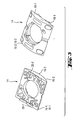
- Fig. 1 shows a first sliding part 2 (sliding unit) with first skids 4-1 and 4-2 and first convex surfaces 6-1, 6-2.
- the first convex surfaces 6-1, 6-2 have the shape of a cylinder section.
- Fig. 1 further shows a mounting plate 8 with first concave surfaces 10-1, 10-2 and first securing devices or protrusions 12-1, 12-2.
- the concave surfaces 10-1, 10-2 have the shape of a hollow cylinder portion and form the joint socket of the sliding bearing. Since only one inclination in a predetermined pivoting plane is possible, the bearing can also be referred to as a hinge.
- the pivoting plane is substantially perpendicular to the axis of the cylinder underlying the cylinder section or to the axis of the hollow cylinder on which the hollow cylinder section is based.
- the first sliding part 2 When assembling the sliding bearing device, the first sliding part 2 is inserted into the mounting plate 8, so that the first convex surfaces 6-1, 6-2 come to lie on the first concave surfaces 10-1, 10-2.
- the first concave surfaces 10-1, 10-2 have the shape of a hollow cylinder portion, wherein the radius of the Hollow cylinder section underlying hollow cylinder is equal to the radius of the cylinder portion of the convex surface underlying cylinder.
- the first sliding skid 4-1 slides with the first convex surface 6-1 on the first concave surface 10-1. Further, the first skid 4-2 slides with the first convex surface 6-2 on the first concave surface 10-2.
- the mounting plate 8 has the first securing device 12-1, 12-2.
- the first securing means is in the form of projections which move in a relative movement of the first slide member 2 to the mounting plate 8 along a circular cutout 24 in the first slide member 2.
- the slide bearing device remains fully functional even when the rotary construction laser falls down, for example, or is turned upside down.
- an inclination of the rotation unit can be achieved solely by providing the first sliding part 2 and the mounting plate 8. This allows an inclination in a first pivoting plane. Slopes in other pivoting planes or free other inclinations can be made possible by a second sliding part 14 (further sliding unit). However, in one embodiment (not shown), tilting in a second pivoting plane may also be possible by other known means.
- the second (further) sliding part 14 has second skids 16-1, 16-2 and second (further) convex surfaces 18-1, 18-2.
- the second convex surfaces 18-1, 18-2 have the shape of a second (further) cylinder portion.
- the second sliding part 14 is inserted into the first sliding part 2.
- the first sliding part 2 has second concave surfaces 20-1, 20-2, which in the assembled sliding bearing device touch the second convex surfaces 18-1, 18-2.
- the second convex surface 18-1 touches the second concave surface 20-1 and the second Convex surface 18-2 contacts the second concave surface 20-2.
- the first sliding part forms with the second concave surfaces 20-1, 20-2 a second (further) joint socket.
- the first sliding part 2 has a second securing device 22.
- the securing device is formed from two projections 22-1, 22-2, which move in a relative movement between the first slide member 2 and the second slide member 14 along concave projections 26-1, 26-2.
- the first concave surfaces 10-1, 10-2 thus form a first "socket". Furthermore, the second concave surfaces 20-1, 20-2 form a second (further) joint socket.
- the first sliding part 2 may also be referred to as a "cross slide", as it forms the center of the sliding bearing device and by means of the first skids 4-1, 4-2 and the second concave surfaces 20-1, 20-2, an inclination of the rotation unit in two allows mutually perpendicular pivot planes.
- the first sliding part 2 may advantageously be made of a sliding-modified material, eg plastic.
- the mounting plate 8 and the second sliding member 14 may be made of non-slip-modified material, eg non-slip-modified plastic.
- the radii of the convex / concave surfaces underlying cylinder / hollow cylinder are substantially equal and the center or the axis of the cylinder or hollow cylinder with a deflection or exit point of the laser (in Fig. 1 not shown, see Fig. 7 ) coincides.
- the height of the rotation unit which is rotatably mounted, for example, in the second sliding member 14, adjusted or adjusted accordingly (see Fig. 7 ).
- Fig. 2 shows a perspective view from above and below the first sliding part 2 (cross slider). Further shows Fig. 3 a perspective view from above and below the second sliding part 14th
- Fig. 4 shows the mounting plate 8 with inserted therein the first sliding part 2.
- the second sliding part 14 is inserted.
- Fig. 4 also shows tension springs 23 which are inserted into corresponding recesses.
- the tension springs By means of the tension springs, the concave surface and the convex surface can be pressed against one another or the further concave surface and the further convex surface can be pressed against one another. It can thus be achieved that the concave surface and convex surface remain in contact in all layers or that a predefined force acts on the sliding surfaces and thus a substantially constant or adjustable sliding property is achieved, essentially independent of the position of the housing of the rotary construction laser.
- Fig. 5 shows a schematic view of the Rotationsbaulasers with mounted in the sliding bearing device laser unit 28.
- the laser unit 28 generates a laser beam L, which is deflected in a deflection point U by means of a (not shown) deflecting device. Due to the position of the deflection point U or exit point of the laser in the center or the axis of the cylinder or hollow cylinder underlying the respective concave or convex surfaces, the deflection point U does not change its position with an inclination of the laser unit 28. In particular, the deflection point U does not change its height A with respect to the mounting plate 8.
- Fig. 6 shows a sectional view of a Rotationsbaulasers 29 with rotation unit 30 and slide bearing device 34, in which a laser unit is mounted.
- the rotation unit 30 is rotatably mounted about a rotational axis of rotation 32.
- the rotary construction laser 29 also has a deflection device 36, by means of which a laser beam L generated in the laser unit can be deflected.
- the deflection point U or exit point of the laser lies in the midpoints or axes of the concave or convex surfaces underlying cylinders or hollow cylinders.
- the rotary construction laser 29 also has at least one drive 38, by means of which the laser unit and thus the rotation unit 30 can be tilted at predeterminable angles.
- Fig. 7a shows a further embodiment of a sliding bearing device 40.
- the sliding bearing device 40 comprises a sliding part 42 with a convex surface 44 in the form of a cylindrical portion and a socket 46.
- the socket pan 46 has two contact areas 48-1, 48-2. Upon insertion of the slider 42 into the socket 46, the convex surface 44 contacts the contact portions 48-1, 48-2.
- the contact areas 48-1, 48-2 have a round shape, so that in each case substantially a contact point between the convex surface 44 and the respective contact area 48-1, 48-2 is formed. In a relative movement of the sliding member 42 relative to the socket pan 46 thus move the contact areas or contact surfaces or contact points along the convex surface and thus on a cylinder portion.
- Fig. 7b shows a further embodiment of a sliding bearing device 50 having a substantially to the Fig. 7a same sliding part 42 with convex surface 44.
- the socket 52 is opposite Fig. 7a differently designed.
- the contact areas 54-1, 54-2 have the shape of a hollow cylinder portion.
- the socket could be V-shaped, so that the convex surface 44 of the slider 42 in the FIGS. 7a and 7b at two points (contact areas) on the inside of the V-shape rests.
- Fig. 8a shows a further embodiment of a sliding bearing device 56 with a sliding part 58 and a socket 62.
- the sliding part 58 has two contact areas 60-1, 60-2 and the socket 62 comprises a concave surface 64 in the form of a hollow cylinder portion.
- the sliding part 58 When inserting the sliding part 58 into the socket 62, the sliding part 58 contacts with its contact areas 60-1, 60-2 the concave surface 64 of the socket 62.
- the contact portions 60-1, 60-2 of the slider 58 move along the concave surface 64 as the slider 58 moves relative to the socket 62.
- Fig. 8b shows a further embodiment of a sliding bearing device 66.
- the joint socket is the same structure as in Fig. 8a , However, the slider 68 has contact portions 70-1, 70-2 with a convex portion in the form of a cylinder portion.
- a first possible embodiment of a sliding bearing device is in the Fig. 1 to 6 shown.
- the sliding unit has a convex surface in the form of a cylinder section and the socket has a concave surface in the form of a hollow cylinder section.
- the second possible embodiment of a sliding bearing device is in the Fig. 7a and 7b shown.
- the sliding part or the sliding unit has a convex surface in the form of a cylinder section.
- the joint socket does not have a concave surface in the form of a hollow cylinder section, but instead contact regions which slide in a movement along the convex surface.
- the third possible embodiment of the sliding bearing device is in the Fig. 8a and 8b shown.
- the socket has a concave surface in the form of a hollow cylinder section.
- the sliding unit has no convex surface (as in the embodiment according to. Figures 1-6 ), but contact areas that slide along the concave surface of the socket during a movement of the joint.
- tension springs by means of which the respective slide member is pressed into the socket.
- socket pan safety devices can be provided fixedly connected to the socket pan safety devices, with which a falling out of the sliding unit from the joint socket can be prevented.
- the materials can be selected as described above.
- suitable choice of materials in the FIGS. 7 and 8 ensure that each slide-modified material, such as plastic, slides on non-slip-modified material.
Abstract
Description
Die Erfindung betrifft einen Lasergerät mit einer Lasereinheit und einer Gleitlagereinrichtung.The invention relates to a laser device with a laser unit and a sliding bearing device.
Dabei ist unter Lasergerät ein Baulaser zu verstehen, wie er im Baugewerbe zu Zwecken der Definition, Übertragung bzw. Nivellierung von Ebenen, Linien oder Punkten eingesetzt wird. Somit lassen sich statische Baulaser wie Punkt- oder Linienlaser ebenso unter dem Begriff Lasergerät subsumieren wie Rotationsbaulaser, bei dem die Lasereinheit einen zumindest teilweise rotierenden Laserstrahl aussendet. Insbesondere kommt die Erfindung bei Rotationsbaulasern mit einer als Rotationseinheit ausgebildeten Lasereinheit zum Einsatz, weswegen sich die nachfolgende Beschreibung zur Vereinfachung auch auf diese Art von Baulaser bezieht. Es sei allerdings darauf hingewiesen, dass dies keine Einschränkung des Schutzumfanges bewirkt und die Erfindung sich ebenso auf alle anderen Arten von Baulasern mit einer verstellbaren Lasereinheit bezieht.Laser equipment means a construction laser, as it is used in the construction industry for purposes of defining, transmitting or leveling planes, lines or points. Thus, static construction lasers such as point or line lasers can also be subsumed under the term laser device, as are rotary construction lasers in which the laser unit emits an at least partially rotating laser beam. In particular, the invention is used in rotary construction lasers with a laser unit designed as a rotation unit, which is why the following description refers to this type of construction laser for the sake of simplicity. It should be noted, however, that this does not limit the scope of protection and the invention also applies to all other types of construction lasers with an adjustable laser unit.
Rotationsbaulaser mit einer als Rotationseinheit ausgebildeten Lasereinheit, die einen zumindest teilweise rotierenden Laserstrahl aussendet, werden vor allem im Baugewerbe eingesetzt, um auf Wänden, Decken und Böden, horizontale, vertikale oder definiert geneigte Ebenen zu erzeugen und festzulegen. Rotationsbaulaser werden auch, beispielsweise im Scanbetrieb, dazu verwendet, vordefinierte Abschnitte von Ebenen oder Markierungen (Punkte, Striche, etc.) festzulegen bzw. als Bezug zu erzeugen.Rotary construction laser with a trained as a rotating unit laser unit that emits an at least partially rotating laser beam are used primarily in the construction industry to create and set on walls, ceilings and floors, horizontal, vertical or defined inclined planes. Rotary construction lasers are also used, for example in the scanning mode, to define predefined sections of planes or markings (points, lines, etc.) or to generate them as a reference.
Bei Rotationsbaulasern ist eine robuste Konstruktion von großer Bedeutung, da die Geräte im Baugewerbe außerordentlichen Belastungen ausgesetzt sind. Gleichzeitig müssen die Geräte eine hohe Präzision aufweisen. Die Festlegung von Ebenen oder Markierungen oder dergleichen muss mit einer hohen Präzision erfolgen.With rotary construction lasers a robust construction is of great importance, since the equipment in the construction industry is exposed to extraordinary loads. At the same time, the devices must have high precision. The definition of levels or markings or the like must be done with high precision.
Es ist also wichtig, eine robuste Konstruktion des Rotationsbaulasers zu realisieren, wobei eine Einstellung eines vorgegebenen Neigungswinkels der Rotationseinheit bezüglich des Gehäuses des Rotationsbaulasers präzise und einfach ist.It is thus important to realize a robust construction of the rotary construction laser, wherein adjustment of a given angle of inclination of the rotary unit with respect to the housing of the rotary construction laser is precise and easy.
Eine Lagereinrichtung zum Neigen bzw. Justieren der Rotationseinheit des Rotationsbaulasers muss daher robust sein und leicht einstellbar. Dabei wird die Rotationseinheit mittels der Lagereinrichtung im Wesentlichen justiert. D.h., in der Regel erfolgt vor der Justage eine Grobeinstellung, beispielsweise von einer Bedienperson. Dies kann beispielsweise von Hand unter Zuhilfenahme von von außen sichtbaren am Rotationsbaulaser angebrachten Libellen erfolgen. Anschließend kann die Bedienperson eine automatische Justage einleiten, bei der die Rotationseinheit beispielsweise mittels Servomotoren und der Lagereinrichtung fein eingestellt (justiert) wird.A bearing device for tilting or adjusting the rotation unit of the Rotationsbaulasers must therefore be robust and easily adjustable. In this case, the rotation unit is substantially adjusted by means of the bearing device. In other words, as a rule, a coarse adjustment takes place before the adjustment, for example by an operator. This can be done, for example, by hand with the help of visible from the outside on Rotationsbaulaser attached dragonflies. Subsequently, the operator can initiate an automatic adjustment, in which the rotation unit is finely adjusted (adjusted), for example by means of servomotors and the bearing device.
Der Erfindung liegt die Aufgabe zugrunde, einen Rotationsbaulaser bereitzustellen, der oben genannten Anforderungen gerecht wird. Weitere Vorteile des Rotationsbaulasers ergeben sich aus der folgenden Beschreibung.The invention has for its object to provide a Rotationsbaulaser that meets the above requirements. Further advantages of Rotationsbaulasers will become apparent from the following description.
Die Aufgabe wird durch die Merkmale des Anspruchs 1 gelöst. Vorteilhafte Weiterbildungen ergeben sich aus den abhängigen Ansprüchen.The object is solved by the features of claim 1. Advantageous developments emerge from the dependent claims.
Der hier beschriebene Rotationsbaulaser weist eine Rotationseinheit auf. Die Rotationseinheit kann beispielsweise mit Kugellagern drehbar um eine Drehachse gelagert sein und eine Umlenkeinrichtung aufweisen. Die Umlenkeinrichtung kann dabei dazu dienen, den Laserstrahl umzulenken.The rotary construction laser described here has a rotation unit. The rotation unit can be rotatably mounted, for example, with ball bearings about an axis of rotation and have a deflection device. The deflection device can serve to deflect the laser beam.
Der Rotationsbaulaser umfasst ferner eine Gleitlagereinrichtung mit einer Gelenkpfanne und einer Gleiteinheit bzw. einem ersten Gleitteil. Die Gleiteinheit weist eine Konvexfläche in Form eines Zylinderabschnitts und die Gelenkpfanne eine Konkavfläche in Form eines Hohlzylinderabschnitts auf, so dass die Konvexfläche in die Konkavfläche eingreifen kann. Die Rotationseinheit ist mit der Gleiteinheit verbunden, so dass sich die Rotationseinheit bei einer Relativbewegung zwischen Konvexfläche und Konkavfläche in einer Schwenkebene neigt.The rotary construction laser further comprises a sliding bearing device with a joint socket and a sliding unit or a first sliding part. The slide unit has a convex surface in the form of a cylinder portion and the socket has a concave surface in the form of a hollow cylinder portion, so that the convex surface can engage in the concave surface. The rotation unit is connected to the sliding unit, so that the rotation unit tilts in a pivoting plane during a relative movement between the convex surface and the concave surface.
Die aufeinander gleitenden Konkav- und Konvexflächen können z.B. in Form von ein oder mehreren Gleitkufen gebildet werden. Eine Neigung der Rotationseinheit wird somit durch ein Gleiten der Konvexfläche auf der Konkavfläche bewirkt.The sliding concave and convex surfaces may e.g. be formed in the form of one or more skids. An inclination of the rotation unit is thus caused by a sliding of the convex surface on the concave surface.
Aufgrund der Ausbildung der Gleitlagereinrichtung mittels der beschriebenen Konvex- bzw. Konkavflächen ergibt sich eine sehr gute Verdrehsicherung. Die Gleiteigenschaften sind genau definierbar und ein Verdrehen gegenüber der Achse des dem Zylinderabschnitt zugrunde liegenden Zylinders und der Achse des dem Hohlzylinderabschnitt zugrunde liegenden Hohlzylinders ist nicht möglich.Due to the design of the sliding bearing device by means of the convex or concave surfaces described results in a very good rotation. The sliding properties are precisely definable and twisting relative to the axle the cylinder section underlying the cylinder and the axis of the hollow cylinder section underlying the hollow cylinder is not possible.
Weiterhin ist durch die Ausbildung von relativ großen Gleitflächen eine große mechanische Robustheit gewährleistet. Es findet insbesondere keine Punktlagerung statt. Die Gleitflächen können dabei auch unterbrochen sein oder unterschiedlich breit sein. Sie können beispielsweise auch Aussparungen aufweisen, um so den Reibwiderstand zu verringern. Durch die konkrete Ausgestaltung der Gleitflächen können somit unterschiedlichste Anforderungen erfüllt werden.Furthermore, a large mechanical robustness is ensured by the formation of relatively large sliding surfaces. In particular, there is no point storage. The sliding surfaces can also be interrupted or be of different widths. For example, they can also have recesses so as to reduce the frictional resistance. Due to the specific design of the sliding surfaces thus a wide variety of requirements can be met.
Die Gleitlagerung ergibt also die bereits erwähnte sehr gute Verdrehsicherung. Die guten Gleiteigenschaften werden durch die vordefinierten Gleitflächen realisiert.The plain bearing thus results in the already mentioned very good rotation. The good sliding properties are realized by the predefined sliding surfaces.
Weiterhin wird durch die Ausbildung der Gleitlagereinrichtung mittels der definierten Konkav- bzw. Konvexflächen eine Schwenkebene fest vorgegeben, in der sich die Rotationseinheit neigt. Die Schwenkebene ist dabei im Wesentlichen senkrecht zu der Achse des dem Zylinderabschnitt zugrunde liegenden Zylinders. Es gibt somit eine Vorzugsrichtung (Schwenkebene) in welche die Rotationseinheit neigbar ist. Dies ist ein Vorteil gegenüber anderen Lagerungen, z.B. einer Lagerung mittels Kugel, Kugelkalotte oder Kardangelenk. Bei solchen Lagerungen müssen andere Führungsmittel vorgesehen werden, um eine Neigung in einer Vorzugsrichtung sicher zu stellen. Auf solche Führungsmittel kann also durch die Erfindung verzichtet werden.Furthermore, by the formation of the sliding bearing device by means of the defined concave or convex surfaces, a pivoting plane fixed in which the rotation unit tilts. The pivot plane is substantially perpendicular to the axis of the cylinder section underlying the cylinder. There is thus a preferred direction (pivot plane) in which the rotation unit is tilted. This is an advantage over other bearings, e.g. a storage by means of ball, spherical cap or universal joint. In such bearings other guide means must be provided to ensure an inclination in a preferred direction. On such a guide means can therefore be omitted by the invention.
In einer bevorzugten Ausführungsform kann die Gleiteinheit eine weitere Gleitlagereinrichtung mit einer weiteren Gelenkpfanne und einer weiteren Gleiteinheit (zweites Gleitteil) enthalten. Dabei weist die weitere Gleiteinheit eine weitere Konvexfläche in Form eines weiteren Zylinderabschnitts auf und die weitere Gelenkpfanne eine weitere Konkavfläche in Form eines weiteren Hohlzylinderabschnitts. Dabei kann die weitere Konvexfläche in die weitere Konkavfläche eingreifen, so dass sich die Rotationseinheit bei einer Relativbewegung zwischen der weiteren Konvexfläche und der weiteren Konkavfläche in einer weiteren Schwenkebene neigt. Die weitere Schwenkebene kann dabei unabhängig bzw. unterschiedlich von der Schwenkebene sein.In a preferred embodiment, the sliding unit may include a further sliding bearing device with a further joint socket and a further sliding unit (second sliding part). In this case, the further slide unit has a further convex surface in the form of a further cylinder section and the further socket pan has a further concave surface in the form of a further hollow cylinder section. In this case, the further convex surface engage in the further concave surface, so that the rotation unit tilts at a relative movement between the further convex surface and the further concave surface in a further pivoting plane. The further pivoting plane can be independent or different from the pivoting plane.
In einer bevorzugten Ausführungsform stehen die Schwenkebene und die weitere Schwenkebene in einem vorbestimmten Winkel zueinander. Der Winkel kann dabei unveränderlich sein, so dass der Winkel zwischen den Schwenkebenen durch den vorbestimmten Winkel zwischen den Achsen des Zylinders und Hohlzylinders festgelegt ist. Die Schwenkebene und die weitere Schwenkebene können in einer bevorzugten Ausführungsform auch rechtwinklig zueinander stehen.In a preferred embodiment, the pivot plane and the further pivot plane are at a predetermined angle to each other. The angle can be unchangeable, so that the angle between the pivot planes by the predetermined angle between the axes of the cylinder and the hollow cylinder is fixed. The pivoting plane and the further pivoting plane can in a preferred embodiment also be at right angles to one another.
Weiterhin bevorzugt sind die Radien des Zylinderabschnitts und des Hohlzylinderabschnitts im Wesentlichen gleich. Damit haben die Konkav- und Konvexflächen eine größtmögliche Kontaktfläche und somit eine gute Führung und gute Gleiteigenschaften. Auch die Radien des weiteren Zylinderabschnitts und des weiteren Hohlzylinderabschnitts können in einer weiteren Ausführungsform im Wesentlichen gleich sein. Somit gilt auch hier, dass die weiteren Konkav- bzw. Konvexflächen eine ausreichende Kontaktfläche und somit eine gute Führung bzw. gute Gleiteigenschaften haben. Die Radien des Zylinderabschnitts, des weiteren Zylinderabschnitts, des Hohlzylinderabschnitts und des weiteren Hohlzylinderabschnitts können auch alle im Wesentlichen gleich sein.Further preferably, the radii of the cylinder portion and the hollow cylinder portion are substantially equal. Thus, the concave and convex surfaces have the greatest possible contact surface and thus good guidance and good sliding properties. The radii of the further cylinder section and of the further hollow cylinder section can also be essentially the same in a further embodiment. Thus, here too, the additional concave or convex surfaces have a sufficient contact surface and thus good guidance or good sliding properties. The radii of the cylinder section, of the further cylinder section, of the hollow cylinder section and of the further hollow cylinder section can all also be substantially the same.
In einer weiteren Ausführungsform ist die Umlenkeinrichtung so ausgebildet, dass sie den Laserstrahl an einem dem Austrittspunkt des Laserstrahls entsprechenden Umlenkpunkt umlenkt. Bevorzugt kann der Mittelpunkt bzw. die Achse des dem Zylinderabschnitt zugrunde liegenden Zylinders, der Mittelpunkt bzw. die Achse des dem weiteren Zylinderabschnitts zugrunde liegenden Zylinders, der Mittelpunkt bzw. die Achse des dem Hohlzylinderabschnitt zugrunde liegenden Hohlzylinders und/oder der Mittelpunkt bzw. die Achse des dem weiteren Hohlzylinderabschnitt zugrunde liegenden Hohlzylinders mit dem Umlenkpunkt zusammenfallen.In a further embodiment, the deflection device is designed such that it deflects the laser beam at a deflection point corresponding to the exit point of the laser beam. Preferably, the center or the axis of the cylinder underlying the cylinder section, the center or the axis of the cylinder underlying the further cylinder section, the center or the axis of the hollow cylinder underlying the hollow cylinder section and / or the center or the axis of the further hollow cylinder section underlying hollow cylinder coincide with the deflection point.
Wenn der Mittelpunkt bzw. die Achse des dem Zylinderabschnitt zugrunde liegenden Zylinders, der Mittelpunkt bzw. die Achse des dem weiteren Zylinderabschnitt zugrunde liegenden Zylinders, der Mittelpunkt bzw. die Achse des dem Hohlzylinderabschnitt zugrunde liegenden Hohlzylinders und/oder der Mittelpunkt bzw. die Achse des dem weiteren Hohlzylinderabschnitt zugrunde liegenden Hohlzylinders mit dem Umlenkpunkt zusammenfallen, so verändert sich die Höhe des Umlenkpunkts bei einer Neigung der Rotationseinheit nicht. Damit ist eine einfache Einstellung vordefinierter Winkel ohne komplizierte Berechnungen möglich. Weiterhin kann die Umlenkeinrichtung kompakt in dem Gehäuse des Rotationsbaulasers verbaut werden. Das Gehäuse kann insbesondere einen geringen Abstand zu der Umlenkeinrichtung haben. Dies wäre bei einer Höhenverstellung bzw. einer Änderung des Abstands zwischen Umlenkeinrichtung und innerer Gehäusewand wie sie bei anderen bekannten Lagerungen auftritt nicht möglich. Die hier beschriebene Gleitlagerung ermöglicht also einen kompakten und Platz sparenden Aufbau des Rotationsbaulasers.If the center or the axis of the cylinder section underlying the cylinder section, the center or the axis of the cylinder underlying the further cylinder section, the center or the axis of the hollow cylinder underlying the hollow cylinder section and / or the center or the axis of the hollow cylinder underlying the further hollow cylinder section coincide with the deflection point, the height of the deflection point does not change with an inclination of the rotation unit. This makes it easy to set predefined angles without complicated calculations. Furthermore, the deflection can be compactly installed in the housing of Rotationsbaulasers. The housing may in particular have a small distance from the deflection device. This would not be possible with a height adjustment or a change in the distance between the deflecting device and the inner housing wall, as occurs in other known bearings. The plain bearing described here thus allows a compact and space-saving design of Rotationsbaulasers.
Bevorzugt können Spannfedern vorgesehen werden, mittels welcher die Konkavfläche und die Konvexfläche aneinander pressbar sind bzw. zueinander angezogen werden. Es kann somit erreicht werden, dass die Konkavfläche und Konvexfläche in allen Lagen in Kontakt bleiben. Ebenso können weitere Spannfedern vorgesehen sein, mittels welcher die weitere Konkavfläche und die weitere Konvexfläche aneinander pressbar sind bzw. zueinander angezogen werden. Der Effekt der Federn ist auch hier, dass eine vordefinierte Kraft auf die Gleitflächen wirkt und somit eine im Wesentlichen konstante oder einstellbare Gleiteigenschaft erreicht wird, im Wesentlichen unabhängig von der Lage des Gehäuses des Rotationsbaulasers.Tension springs can preferably be provided, by means of which the concave surface and the convex surface can be pressed against each other or be attracted to one another. It can thus be achieved that the concave surface and convex surface remain in contact in all layers. Likewise, further tension springs may be provided, by means of which the further concave surface and the further convex surface are pressed against each other or are attracted to each other. The effect of the springs is also here that a predefined force acts on the sliding surfaces and thus a substantially constant or adjustable sliding property is achieved, substantially independent of the position of the housing of Rotationsbaulasers.
In einer bevorzugten Ausführungsform kann auch eine mit der Gelenkpfanne fest verbundene Sicherungseinrichtung vorgesehen sein, mittels welcher ein Herausfallen der Gleiteinheit aus der Gelenkpfanne verhinderbar ist. Ähnlich kann auch die weitere Gelenkpfanne eine weitere Sicherungseinrichtung aufweisen, mittels welcher ein Herausfallen der weiteren Gleiteinheit aus der weiteren Gelenkpfanne verhinderbar ist.In a preferred embodiment, a securing device firmly connected to the socket can be provided, by means of which a falling out of the sliding unit from the joint socket can be prevented. Similarly, the further joint socket can also have a further securing device, by means of which a falling out of the further sliding unit from the further joint socket can be prevented.
In einer weiteren bevorzugten Ausführungsform kann die Konvexfläche aus gleitmodifiziertem Material hergestellt sein. Die Konkavfläche kann dabei aus nicht-gleitmodifiziertem Material hergestellt sein, so dass eine gute Gleiteigenschaft erreicht wird. Ebenso kann die weitere Konkavfläche aus gleitmodifiziertem Material hergestellt sein und die Konkavfläche und die weitere Konvexfläche aus nicht-gleitmodifiziertem Material. Beispielsweise kann die Konkavfläche und die weitere Konvexfläche aus normalem Kunststoff hergestellt sein und die Konvexfläche und die weitere Konkavfläche aus gleitmodifiziertem Kunststoff. Somit ergeben sich zwischen der Konkav- und Konvexfläche sowie zwischen der weiteren Konkav- und weiteren Konvexfläche gute Gleiteigenschaften.In a further preferred embodiment, the convex surface may be made of a slip-modified material. The concave surface may be made of non-slip-modified material, so that a good sliding property is achieved. Likewise, the further concave surface can be made of slip-modified material and the concave surface and the further convex surface of non-slip-modified material. For example, the concave surface and the further convex surface may be made of normal plastic and the convex surface and the further concave surface of slip-modified plastic. Thus, good sliding properties arise between the concave and convex surface and between the further concave and further convex surface.
Die Aufgabe wird zudem durch die Merkmale der unabhängigen Ansprüche 16 sowie 20 gelöst. Vorteilhafte Weiterbildungen dieser alternativen Formen ergeben sich aus den hiervon abhängigen Ansprüchen.The object is also achieved by the features of independent claims 16 and 20. Advantageous developments of these alternative forms will become apparent from the dependent claims.
Die Erfindung wird im Folgenden anhand der beigefügten Figuren erläutert. In den Figuren zeigen:
- Fig. 1
- eine perspektivische Ansicht der Bauteile der Gleitlagereinrichtung;
- Fig.2
- eine perspektivische Ansicht des ersten Gleitteils der Gleitlagereinrichtung;
- Fig.3
- ein perspektivische Ansicht des zweiten Gleitteils der Gleitlagereinrichtung;
- Fig. 4
- eine perspektivische Ansicht der zusammengebauten Gleitlagereinrichtung;
- Fig. 5
- eine schematische Ansicht zur Verdeutlichung der Wirkung der Gleitlagereinrichtung;
- Fig. 6
- eine Schnittansicht des Rotationsbaulasers mit Rotationseinheit und Gleitlagereinrichtung;
- Fig.7
- zeigt eine weitere Ausführungsform einer Gleitlagereinrichtung, wobei die Gelenkpfanne Gleitbereiche bzw. Kontaktbereiche aufweist; und
- Fig.8
- zeigt noch eine weitere Ausführungsform einer Gleitlagereinrichtung, wobei das Gleitteil Kontaktbereiche aufweist.
- Fig. 1
- a perspective view of the components of the sliding bearing device;
- Fig.2
- a perspective view of the first sliding part of the sliding bearing device;
- Figure 3
- a perspective view of the second sliding part of the sliding bearing device;
- Fig. 4
- a perspective view of the assembled slide bearing device;
- Fig. 5
- a schematic view to illustrate the effect of the sliding bearing device;
- Fig. 6
- a sectional view of Rotationsbaulasers with rotary unit and slide bearing device;
- Figure 7
- shows a further embodiment of a sliding bearing device, wherein the socket has sliding areas or contact areas; and
- Figure 8
- shows yet another embodiment of a sliding bearing device, wherein the sliding part has contact areas.
Beim Zusammenbau der Gleitlagereinrichtung wird das erste Gleitteil 2 in die Aufbauplatte 8 eingesetzt, so dass die ersten Konvexflächen 6-1, 6-2 auf den ersten Konkavflächen 10-1, 10-2 zu liegen kommen. Um einen guten Kontakt und somit gute Gleiteigenschaften zu erreichen, haben die ersten Konkavflächen 10-1, 10-2 die Form eines Hohlzylinderabschnitts, wobei der Radius des dem Hohlzylinderabschnitt zugrunde liegenden Hohlzylinders gleich dem Radius des dem Zylinderabschnitt der Konvexfläche zugrunde liegenden Zylinders ist.When assembling the sliding bearing device, the first sliding
Beim Zusammenbau der Gleitlagereinrichtung gleitet also die erste Gleitkufe 4-1 mit der ersten Konvexfläche 6-1 auf der ersten Konkavfläche 10-1. Ferner gleitet die erste Gleitkufe 4-2 mit der ersten Konvexfläche 6-2 auf der ersten Konkavfläche 10-2.During assembly of the sliding bearing device, therefore, the first sliding skid 4-1 slides with the first convex surface 6-1 on the first concave surface 10-1. Further, the first skid 4-2 slides with the first convex surface 6-2 on the first concave surface 10-2.
Um ein Herausfallen des ersten Gleitteils 2 aus der Aufbauplatte 8 zu verhindern, weist die Aufbauplatte 8 die erste Sicherungseinrichtung 12-1, 12-2 auf. Wie
Bei einem Gleiten der ersten Konvexflächen 6-1, 6-2 auf den ersten Konkavflächen 10-1, 10-2 kann eine mit dem ersten Gleitteil 2 verbundene Rotationseinheit (in
Erfindungsgemäß kann also eine Neigung der Rotationseinheit allein durch Bereitstellen des ersten Gleitteils 2 und der Aufbauplatte 8 erreicht werden. Damit ist eine Neigung in einer ersten Schwenkebene möglich. Neigungen in anderen Schwenkebenen oder freie andere Neigungen können durch ein zweites Gleitteil 14 (weitere Gleiteinheit) ermöglicht werden. In einer (nicht dargestellten) Ausführungsform kann eine Neigung in einer zweiten Schwenkebene jedoch auch durch andere bekannte Mittel möglich sein.According to the invention, therefore, an inclination of the rotation unit can be achieved solely by providing the first sliding
Das zweite (weitere) Gleitteil 14 weist zweite Gleitkufen 16-1, 16-2 und zweite (weitere) Konvexflächen 18-1, 18-2 auf. Die zweiten Konvexflächen 18-1, 18-2 haben die Form eines zweiten (weiteren) Zylinderabschnitts.The second (further) sliding
Um die Neigung in der zweiten Schwenkebene zu realisieren, wird das zweite Gleitteil 14 in das erste Gleitteil 2 eingesetzt. Hierzu weist das erste Gleitteil 2 zweite Konkavflächen 20-1, 20-2 auf, die bei der zusammengebauten Gleitlagereinrichtung die zweiten Konvexflächen 18-1, 18-2 berühren. Die zweite Konvexfläche 18-1 berührt dabei die zweite Konkavfläche 20-1 und die zweite Konvexfläche 18-2 berührt die zweite Konkavfläche 20-2. Das erste Gleitteil bildet mit den zweiten Konkavflächen 20-1, 20-2 eine zweite (weitere) Gelenkpfanne.In order to realize the inclination in the second pivoting plane, the second sliding
Um ein Herausfallen des zweiten Gleitteils 14 aus dem ersten Gleitteil 2 zu verhindern, weist das erste Gleitteil 2 eine zweite Sicherungseinrichtung 22 auf. Die Sicherungseinrichtung ist aus zwei Vorsprüngen 22-1, 22-2 gebildet, die sich bei einer Relativbewegung zwischen dem ersten Gleitteil 2 und dem zweiten Gleitteil 14 entlang konkavförmiger Vorsprünge 26-1, 26-2 bewegen.In order to prevent the second sliding
Die ersten Konkavflächen 10-1, 10-2 bilden somit eine erste "Gelenkpfanne". Ferner bilden die zweiten Konkavflächen 20-1, 20-2 eine zweite (weitere) Gelenkpfanne.The first concave surfaces 10-1, 10-2 thus form a first "socket". Furthermore, the second concave surfaces 20-1, 20-2 form a second (further) joint socket.
Wie bereits oben angedeutet, kann mit der Erfindung auch nur eine Neigung in einer Schwenkebene erreicht werden. Es ist daher für die Erfindung ausreichend, die Gleitlagereinrichtung durch Einsetzen des ersten Gleitteils 2 in die Aufbauplatte 8 zu realisieren. Für eine Realisierung von Neigungen, die von der ersten Schwenkebene bzw. Neigungsebene abweichen, können beliebige Mittel vorgesehen sein. Das Vorsehen eines zweiten Gleitteils 14 wie in
Das erste Gleitteil 2 kann auch als "Kreuzgleiter" bezeichnet werden, da es gleichsam das Mittelstück der Gleitlagereinrichtung bildet und mittels der ersten Gleitkufen 4-1, 4-2 und den zweiten Konkavflächen 20-1, 20-2 eine Neigung der Rotationseinheit in zwei zueinander senkrecht stehenden Schwenkebenen ermöglicht.The first sliding
An dieser Stelle sei angemerkt, dass es keinesfalls zwingend ist, dass die beiden Schwenkebenen senkrecht zueinander stehen. Alle in der Beschreibung genannten Vorteile können auch erreicht werden, wenn dies nicht der Fall ist und die Schwenkebenen in einem vorbestimmten anderen Winkel zueinander stehen.It should be noted that it is by no means mandatory that the two pivot planes are perpendicular to each other. All the advantages mentioned in the description can also be achieved if this is not the case and the pivoting levels are at a predetermined other angle to each other.
Das erste Gleitteil 2 kann vorteilhafterweise aus gleitmodifiziertem Material, z.B. Kunststoff, hergestellt sein. Weiter können die Aufbauplatte 8 und das zweite Gleitteil 14 aus nicht gleitmodifiziertem Material, z.B. nicht gleitmodifiziertem Kunststoff, hergestellt sein. Somit ergeben sich entlang aller Gleitflächen 10-1, 10-2, 6-1, 6-2, 20-1, 20-2, 18-1, 18-2 gute Gleiteigenschaften, da jeweils nicht gleitmodifiziertes Material auf gleitmodifiziertem Material gleitet.The first sliding
Bezüglich der Konkav- bzw. Konvexflächen in
Der Rotationsbaulaser 29 weist ferner eine Umlenkeinrichtung 36 auf, mittels der ein in der Lasereinheit erzeugter Laserstrahl L umgelenkt werden kann. Der Umlenkpunkt U bzw. Austrittspunkt des Lasers liegt dabei in den Mittelpunkten bzw. Achsen der den Konkav- bzw. Konvexflächen zugrunde liegenden Zylindern bzw. Hohlzylindern.The
Der Rotationsbaulaser 29 weist ferner wenigstens einen Antrieb 38 auf, mittels welchem die Lasereinheit und somit die Rotationseinheit 30 in vorgebbare Winkel neigbar ist.The
Die Gelenkpfanne 46 weist zwei Kontaktbereiche 48-1, 48-2 auf. Bei einem Einsetzen des Gleitteils 42 in die Gelenkpfanne 46 berührt die Konvexfläche 44 die Kontaktbereiche 48-1, 48-2. In der Ausführungsform von
Es sind weitere Formen der Gelenkpfanne denkbar. Beispielsweise könnte die Gelenkpfanne V-förmig sein, sodass die Konvexfläche 44 des Gleitteils 42 in den
Bei einem Einsetzen des Gleitteils 58 in die Gelenkpfanne 62 berührt das Gleitteil 58 mit seinen Kontaktbereichen 60-1, 60-2 die Konkavfläche 64 der Gelenkpfanne 62.When inserting the sliding
Somit bewegen sich die Kontaktbereiche 60-1, 60-2 des Gleitteils 58 bei einer Bewegung des Gleitteils 58 relativ zu der Gelenkpfanne 62 entlang der Konkavfläche 64.Thus, the contact portions 60-1, 60-2 of the
In obiger Beschreibung wurden drei verschiedene Ausführungsformen von Gleitlagereinrichtungen beschrieben. Eine erste mögliche Ausführungsform einer Gleitlagereinrichtung ist in den
Es sind nun zur Realisierung von zwei oder mehr Schwenkebenen der Lasereinheit beliebige Kombinationen der drei beschriebenen Ausführungsformen der Gleitlagereinrichtungen möglich.There are now possible for the realization of two or more pivot planes of the laser unit any combination of the three described embodiments of the sliding bearing devices.
Beispielsweise kann das Neigen der Lasereinheit in einer ersten Schwenkebene mittels einer Gleitlagereinrichtung gemäß der ersten Ausführungsform (
Es sind beliebige Permutationen denkbar.Any permutations are conceivable.
Des Weiteren sind alle zuvor im Zusammenhang mit den
Beispielsweise können bei den Gleitlagereinrichtungen gemäß
Weiterhin können die Materialien wie zuvor beschrieben gewählt werden. Beispielsweise kann durch geeignete Wahl der Materialien in den
Claims (24)
einem Laser zur Erzeugung eines Laserstrahls (L), und
einer in der Lasereinheit (30) angeordneten Umlenkeinrichtung (36) zum Umlenken des Laserstrahls an einem Umlenkpunkt (U),
wobei der Mittelpunkt des dem Zylinderabschnitt zugrunde liegenden Zylinders, der Mittelpunkt des dem weiteren Zylinderabschnitt zugrunde liegenden Zylinders, der Mittelpunkt des dem Hohlzylinderabschnitt zugrunde liegenden Hohlzylinders und/oder der Mittelpunkt des dem weiteren Hohlzylinderabschnitt zugrunde liegenden Hohlzylinders mit dem Umlenkpunkt zusammenfallen.Laser device according to one of claims 1 to 7, with
a laser for generating a laser beam (L), and
a deflection device (36) arranged in the laser unit (30) for deflecting the laser beam at a deflection point (U),
wherein the center of the cylindrical portion underlying the cylinder, the center of the cylinder portion underlying the cylinder, the center of the hollow cylinder portion underlying the hollow cylinder and / or the center of the further hollow cylinder portion underlying the hollow cylinder coincide with the deflection point.
einer in der Lasereinheit (30) angeordneten Umlenkeinrichtung (36) zum Umlenken des Laserstrahls an einem Umlenkpunkt (U),
wobei der Mittelpunkt des dem Zylinderabschnitt zugrunde liegenden Zylinders mit dem Umlenkpunkt zusammenfällt.Laser apparatus according to one of claims 16 to 17, comprising a laser for generating a laser beam (L), and
a deflection device (36) arranged in the laser unit (30) for deflecting the laser beam at a deflection point (U),
wherein the center of the cylinder portion underlying the cylinder coincides with the deflection point.
einer in der Lasereinheit (30) angeordneten Umlenkeinrichtung (36) zum Umlenken des Laserstrahls an einem Umlenkpunkt (U),
wobei der Mittelpunkt des dem Hohlzylinderabschnitt zugrunde liegenden Hohlzylinders mit dem Umlenkpunkt zusammenfällt.Laser device according to one of claims 20 to 21, comprising a laser for generating a laser beam (L), and
a deflection device (36) arranged in the laser unit (30) for deflecting the laser beam at a deflection point (U),
wherein the center of the hollow cylinder underlying the hollow cylinder coincides with the deflection point.
Applications Claiming Priority (1)
| Application Number | Priority Date | Filing Date | Title |
|---|---|---|---|
| DE102008041029A DE102008041029A1 (en) | 2008-08-06 | 2008-08-06 | laser device |
Publications (3)
| Publication Number | Publication Date |
|---|---|
| EP2154474A2 true EP2154474A2 (en) | 2010-02-17 |
| EP2154474A3 EP2154474A3 (en) | 2014-01-08 |
| EP2154474B1 EP2154474B1 (en) | 2018-05-30 |
Family
ID=41264244
Family Applications (1)
| Application Number | Title | Priority Date | Filing Date |
|---|---|---|---|
| EP09164736.2A Active EP2154474B1 (en) | 2008-08-06 | 2009-07-07 | Laser device |
Country Status (5)
| Country | Link |
|---|---|
| US (1) | US8061046B2 (en) |
| EP (1) | EP2154474B1 (en) |
| JP (1) | JP5603574B2 (en) |
| CN (1) | CN101645575A (en) |
| DE (1) | DE102008041029A1 (en) |
Cited By (1)
| Publication number | Priority date | Publication date | Assignee | Title |
|---|---|---|---|---|
| WO2017044183A1 (en) * | 2015-09-10 | 2017-03-16 | Siemens Industry, Inc. | Mounting arrangement for railway wayside signal applications |
Families Citing this family (8)
| Publication number | Priority date | Publication date | Assignee | Title |
|---|---|---|---|---|
| DE102008041029A1 (en) * | 2008-08-06 | 2010-02-11 | Hilti Aktiengesellschaft | laser device |
| JP5550855B2 (en) * | 2009-06-12 | 2014-07-16 | 株式会社トプコン | Rotating laser emission device |
| US8908727B2 (en) | 2013-03-15 | 2014-12-09 | Emcore Corporation | Laser assembly and method for manufacturing the same |
| US9178331B2 (en) | 2013-05-23 | 2015-11-03 | Heino Bukkems | Micro-integratable tunable laser assembly |
| US20150162723A1 (en) | 2013-12-09 | 2015-06-11 | Emcore Corporation | Small packaged tunable laser |
| US10006768B2 (en) * | 2016-03-15 | 2018-06-26 | Stanley Black & Decker Inc. | Laser level |
| CN107257080B (en) * | 2017-06-30 | 2019-12-24 | 联想(北京)有限公司 | Laser fixing device, laser film generating device and adjusting method thereof |
| CN111272155A (en) * | 2020-03-31 | 2020-06-12 | 中铁隧道局集团有限公司 | Total station sealing protection device used under sea condition |
Citations (3)
| Publication number | Priority date | Publication date | Assignee | Title |
|---|---|---|---|---|
| US6763596B1 (en) * | 2002-08-23 | 2004-07-20 | Chicago Steel Tape Co. | Laser alignment device |
| US20050155238A1 (en) * | 2003-07-01 | 2005-07-21 | Levine Steven R. | Laser line generating device with swivel base |
| DE202006004049U1 (en) * | 2006-03-15 | 2006-06-08 | Precaster Enterprises Co., Ltd. | Adjustable tripod for laser leveling device has body, seat, measuring device and azimuth micro-adjustment which is fitted at height of micro-adjustment to rotatably hold seat of laser leveling device |
Family Cites Families (12)
| Publication number | Priority date | Publication date | Assignee | Title |
|---|---|---|---|---|
| JPS63262530A (en) * | 1987-04-20 | 1988-10-28 | Pioneer Electronic Corp | Measuring apparatus for birefringence |
| JPH0443839Y2 (en) * | 1987-09-19 | 1992-10-15 | ||
| JPH0459682U (en) * | 1990-09-28 | 1992-05-21 | ||
| JPH07209453A (en) * | 1994-01-13 | 1995-08-11 | Hitachi Ltd | Sample stage |
| JPH1065999A (en) * | 1996-08-14 | 1998-03-06 | Sony Corp | Tilt stand |
| US6073354A (en) * | 1998-01-20 | 2000-06-13 | Levelite Technology, Inc. | Plumb laser beam generator with floating telescope |
| SE523035C2 (en) * | 2000-04-13 | 2004-03-23 | Saab Ab | Tools for fixing hull details |
| DE10325859B3 (en) * | 2003-06-06 | 2004-06-03 | Hilti Ag | Rotational laser has deflection device for laser beam supported by spherical pivot mounting allowing laser beam rotational plane to be angled |
| TWM247820U (en) * | 2003-10-17 | 2004-10-21 | Quarton Inc | Laser apparatus which can be hung upside down |
| CN101078623B (en) * | 2006-05-26 | 2010-05-12 | 南京德朔实业有限公司 | Self-levelling straight line laser and its control method |
| DE102008041029A1 (en) * | 2008-08-06 | 2010-02-11 | Hilti Aktiengesellschaft | laser device |
| DE102008041033A1 (en) * | 2008-08-06 | 2010-02-11 | Hilti Aktiengesellschaft | A rotary construction |
-
2008
- 2008-08-06 DE DE102008041029A patent/DE102008041029A1/en not_active Ceased
-
2009
- 2009-07-07 EP EP09164736.2A patent/EP2154474B1/en active Active
- 2009-08-04 CN CN200910161133A patent/CN101645575A/en active Pending
- 2009-08-04 JP JP2009181541A patent/JP5603574B2/en active Active
- 2009-08-05 US US12/536,430 patent/US8061046B2/en active Active
Patent Citations (3)
| Publication number | Priority date | Publication date | Assignee | Title |
|---|---|---|---|---|
| US6763596B1 (en) * | 2002-08-23 | 2004-07-20 | Chicago Steel Tape Co. | Laser alignment device |
| US20050155238A1 (en) * | 2003-07-01 | 2005-07-21 | Levine Steven R. | Laser line generating device with swivel base |
| DE202006004049U1 (en) * | 2006-03-15 | 2006-06-08 | Precaster Enterprises Co., Ltd. | Adjustable tripod for laser leveling device has body, seat, measuring device and azimuth micro-adjustment which is fitted at height of micro-adjustment to rotatably hold seat of laser leveling device |
Cited By (2)
| Publication number | Priority date | Publication date | Assignee | Title |
|---|---|---|---|---|
| WO2017044183A1 (en) * | 2015-09-10 | 2017-03-16 | Siemens Industry, Inc. | Mounting arrangement for railway wayside signal applications |
| US10710618B2 (en) | 2015-09-10 | 2020-07-14 | Siemens Mobility, Inc. | Mounting arrangement for railway wayside signal applications |
Also Published As
| Publication number | Publication date |
|---|---|
| US8061046B2 (en) | 2011-11-22 |
| EP2154474B1 (en) | 2018-05-30 |
| CN101645575A (en) | 2010-02-10 |
| JP5603574B2 (en) | 2014-10-08 |
| DE102008041029A1 (en) | 2010-02-11 |
| US20100031520A1 (en) | 2010-02-11 |
| JP2010038919A (en) | 2010-02-18 |
| EP2154474A3 (en) | 2014-01-08 |
Similar Documents
| Publication | Publication Date | Title |
|---|---|---|
| EP2154474B1 (en) | Laser device | |
| EP3680129B1 (en) | Vehicle seat | |
| WO2011085774A1 (en) | Piece of furniture and device for a piece of furniture | |
| DE2502619B2 (en) | Kit for assembling a frame intended to hold instruments, in particular laboratory instruments | |
| EP0035143B1 (en) | Hinge fitting for all-glass doors | |
| DE102006028832A1 (en) | Device for guiding a body and steering column for a motor vehicle | |
| DE2736393A1 (en) | ADJUSTABLE PIN BEARING FOR PIVOT WINDOW | |
| WO2001031386A1 (en) | Spring hinge for spectacles and method for dismantling a spectacles spring hinge | |
| DE102009045653B4 (en) | Rail of a longitudinal guide with a bearing block and a pivoting flap | |
| EP1126114B1 (en) | Adjustable hinge | |
| EP0118050A2 (en) | Adjusting device for the flaps of a hinge | |
| DE60319855T2 (en) | ROTATABLE CONNECTION | |
| EP1959231A2 (en) | Levelling, plumbing, and angle calibration instrument with a pendulously suspended plumb bob | |
| EP3884554B1 (en) | Electric installation device | |
| EP0525507A2 (en) | Device for adjusting the actuator for displacement volume control of a hydrostatic machine | |
| DE2529562C2 (en) | Armature guide for an electrical switchgear | |
| EP3786405B1 (en) | Furniture drive for moving a movable furniture part | |
| DE4342275C1 (en) | External double-jaw brake for a spinning spindle | |
| EP1245773B1 (en) | Fine-framed doors | |
| DE102012222210A1 (en) | For concealed arrangement provided corner bearing | |
| EP3320805B1 (en) | Rocking mechanism for a chair | |
| DE102011012388B3 (en) | Adjuster for alignment of laser collimator utilized for emitting laser line or laser spot, has bars connected with sides of base part and carrier component such that twist of component is enabled | |
| DE19619739C1 (en) | Height adjustment device for computer monitor screen | |
| DE102019102602A1 (en) | Optical assembly with an optical mount and a strip optic | |
| DE10313842A1 (en) | Cabinet door e.g. for distribution-cabinet or meter-cabinet, uses housing projection from which rotary axis pin extends to fill recess |
Legal Events
| Date | Code | Title | Description |
|---|---|---|---|
| PUAI | Public reference made under article 153(3) epc to a published international application that has entered the european phase |
Free format text: ORIGINAL CODE: 0009012 |
|
| AK | Designated contracting states |
Kind code of ref document: A2 Designated state(s): CH DE FR IT LI |
|
| AX | Request for extension of the european patent |
Extension state: AL BA RS |
|
| PUAL | Search report despatched |
Free format text: ORIGINAL CODE: 0009013 |
|
| AK | Designated contracting states |
Kind code of ref document: A3 Designated state(s): CH DE FR IT LI |
|
| AX | Request for extension of the european patent |
Extension state: AL BA RS |
|
| RIC1 | Information provided on ipc code assigned before grant |
Ipc: F16M 11/16 20060101ALI20131204BHEP Ipc: G01C 15/00 20060101AFI20131204BHEP |
|
| 17P | Request for examination filed |
Effective date: 20140708 |
|
| RBV | Designated contracting states (corrected) |
Designated state(s): CH DE FR IT LI |
|
| GRAP | Despatch of communication of intention to grant a patent |
Free format text: ORIGINAL CODE: EPIDOSNIGR1 |
|
| INTG | Intention to grant announced |
Effective date: 20180103 |
|
| GRAJ | Information related to disapproval of communication of intention to grant by the applicant or resumption of examination proceedings by the epo deleted |
Free format text: ORIGINAL CODE: EPIDOSDIGR1 |
|
| GRAP | Despatch of communication of intention to grant a patent |
Free format text: ORIGINAL CODE: EPIDOSNIGR1 |
|
| INTC | Intention to grant announced (deleted) | ||
| INTG | Intention to grant announced |
Effective date: 20180223 |
|
| GRAS | Grant fee paid |
Free format text: ORIGINAL CODE: EPIDOSNIGR3 |
|
| GRAA | (expected) grant |
Free format text: ORIGINAL CODE: 0009210 |
|
| AK | Designated contracting states |
Kind code of ref document: B1 Designated state(s): CH DE FR IT LI |
|
| REG | Reference to a national code |
Ref country code: CH Ref legal event code: EP |
|
| REG | Reference to a national code |
Ref country code: DE Ref legal event code: R096 Ref document number: 502009014992 Country of ref document: DE |
|
| REG | Reference to a national code |
Ref country code: FR Ref legal event code: PLFP Year of fee payment: 10 |
|
| REG | Reference to a national code |
Ref country code: DE Ref legal event code: R097 Ref document number: 502009014992 Country of ref document: DE |
|
| PLBE | No opposition filed within time limit |
Free format text: ORIGINAL CODE: 0009261 |
|
| STAA | Information on the status of an ep patent application or granted ep patent |
Free format text: STATUS: NO OPPOSITION FILED WITHIN TIME LIMIT |
|
| 26N | No opposition filed |
Effective date: 20190301 |
|
| PGFP | Annual fee paid to national office [announced via postgrant information from national office to epo] |
Ref country code: IT Payment date: 20230724 Year of fee payment: 15 Ref country code: CH Payment date: 20230801 Year of fee payment: 15 |
|
| PGFP | Annual fee paid to national office [announced via postgrant information from national office to epo] |
Ref country code: FR Payment date: 20230725 Year of fee payment: 15 Ref country code: DE Payment date: 20230719 Year of fee payment: 15 |