EP2154097B1 - Lift belt for a lift system and method for manufacturing such a lift belt - Google Patents
Lift belt for a lift system and method for manufacturing such a lift belt Download PDFInfo
- Publication number
- EP2154097B1 EP2154097B1 EP09175749A EP09175749A EP2154097B1 EP 2154097 B1 EP2154097 B1 EP 2154097B1 EP 09175749 A EP09175749 A EP 09175749A EP 09175749 A EP09175749 A EP 09175749A EP 2154097 B1 EP2154097 B1 EP 2154097B1
- Authority
- EP
- European Patent Office
- Prior art keywords
- belt
- drive wheel
- tensile
- part belt
- lift
- Prior art date
- Legal status (The legal status is an assumption and is not a legal conclusion. Google has not performed a legal analysis and makes no representation as to the accuracy of the status listed.)
- Not-in-force
Links
Images

Classifications
-
- B—PERFORMING OPERATIONS; TRANSPORTING
- B66—HOISTING; LIFTING; HAULING
- B66B—ELEVATORS; ESCALATORS OR MOVING WALKWAYS
- B66B7/00—Other common features of elevators
- B66B7/06—Arrangements of ropes or cables
-
- B—PERFORMING OPERATIONS; TRANSPORTING
- B66—HOISTING; LIFTING; HAULING
- B66B—ELEVATORS; ESCALATORS OR MOVING WALKWAYS
- B66B7/00—Other common features of elevators
- B66B7/06—Arrangements of ropes or cables
- B66B7/062—Belts
-
- B—PERFORMING OPERATIONS; TRANSPORTING
- B29—WORKING OF PLASTICS; WORKING OF SUBSTANCES IN A PLASTIC STATE IN GENERAL
- B29D—PRODUCING PARTICULAR ARTICLES FROM PLASTICS OR FROM SUBSTANCES IN A PLASTIC STATE
- B29D29/00—Producing belts or bands
- B29D29/10—Driving belts having wedge-shaped cross-section
-
- B—PERFORMING OPERATIONS; TRANSPORTING
- B66—HOISTING; LIFTING; HAULING
- B66B—ELEVATORS; ESCALATORS OR MOVING WALKWAYS
- B66B7/00—Other common features of elevators
-
- F—MECHANICAL ENGINEERING; LIGHTING; HEATING; WEAPONS; BLASTING
- F16—ENGINEERING ELEMENTS AND UNITS; GENERAL MEASURES FOR PRODUCING AND MAINTAINING EFFECTIVE FUNCTIONING OF MACHINES OR INSTALLATIONS; THERMAL INSULATION IN GENERAL
- F16G—BELTS, CABLES, OR ROPES, PREDOMINANTLY USED FOR DRIVING PURPOSES; CHAINS; FITTINGS PREDOMINANTLY USED THEREFOR
- F16G1/00—Driving-belts
- F16G1/28—Driving-belts with a contact surface of special shape, e.g. toothed
-
- D—TEXTILES; PAPER
- D07—ROPES; CABLES OTHER THAN ELECTRIC
- D07B—ROPES OR CABLES IN GENERAL
- D07B1/00—Constructional features of ropes or cables
- D07B1/22—Flat or flat-sided ropes; Sets of ropes consisting of a series of parallel ropes
-
- D—TEXTILES; PAPER
- D07—ROPES; CABLES OTHER THAN ELECTRIC
- D07B—ROPES OR CABLES IN GENERAL
- D07B2201/00—Ropes or cables
- D07B2201/20—Rope or cable components
- D07B2201/2083—Jackets or coverings
- D07B2201/2087—Jackets or coverings being of the coated type
-
- D—TEXTILES; PAPER
- D07—ROPES; CABLES OTHER THAN ELECTRIC
- D07B—ROPES OR CABLES IN GENERAL
- D07B2501/00—Application field
- D07B2501/20—Application field related to ropes or cables
- D07B2501/2007—Elevators
Definitions
- the present invention relates to a belt for an elevator installation, to a manufacturing method for such a belt and to an elevator installation with such a belt.
- An elevator installation comprises an elevator cage and, as a rule, a counterweight, which are movable in an elevator shaft or along free-standing guide devices.
- the elevator installation has at least one drive unit with at least one traction sheave each, which carries the elevator car and the counterweight via one or more belts and / or transmits the required drive forces thereto.
- the elevator car and the counterweight can be connected via the same belt, which are guided over the traction sheave (s) and act both as a support means and as a drive means.
- the elevator car and the counterweight can also be carried on separate straps and driven by separate drive belt.
- a belt according to the present invention can be used for any of the functions described above, that is, as a combined drive and carrying belt, as a carrying strap, which runs over at least one deflection wheel (carrying roller) and connects the elevator car with the counterweight and carries both, or as a drive belt , which has only drive function and at least one traction sheave.
- Such belts for elevator installations usually comprise a belt body made of an elastomer.
- tension members in the form of steel and / or plastic cords are embedded in the belt body.
- the cords may be formed, for example, as strands or ropes made of steel wires or plastic fibers. They are advantageously arranged in the neutral fiber of the belt cross-section, in which no tensile or compressive stresses occur when looping around a belt pulley.
- the belt on a drive wheel facing the traction side has a rib arrangement with a plurality of extending in the longitudinal direction of the belt wedge-shaped ribs which engage in corresponding grooves on the drive wheel.
- the output shaft of the drive unit itself may be designed as a drive wheel.
- the tensile carriers are embedded in a matrix of a soft elastomer, in particular polyurethane (PU), polychloroprene (CR) or ethylene-propylene-diene rubber (EPDM).
- PU polyurethane
- CR polychloroprene
- EPDM ethylene-propylene-diene rubber
- Such belts can not or only partially be used in safety-sensitive devices such as an elevator system, since the risk of a belt break due to the damage described above is too high. Likewise, such straps can not be used to transmit high forces as this increases the risk of such damage.
- An object of the present invention is therefore to provide an elevator system in which the risk of failure due to a belt breakage is reduced. Another object of the present invention is to provide a belt for such an elevator system, which can also transmit higher forces. Another object of the present invention is to provide a method of manufacturing such a belt.
- a belt according to the features of claim 1 a manufacturing method according to the features of claim 11 and an elevator installation according to the features of claim 14 are provided.
- a belt for an elevator system comprises a first part belt of a first material in which a tension member assembly having at least one tensile member of steel wire or steel wire strands or steel wire ropes is arranged, and a second part belt of a second, of the first material different material.
- the first material comprises at least one thermoplastic.
- This thermoplastic material is preferably polyamide (PA), polyethylene (PE), polycarbonate (PC) or polyvinyl chloride (PVC).
- the first material may also comprise a blend of two or more thermoplastics, a so-called polyblend.
- the first material may also contain additives, in particular fibers such as carbon or glass fibers.
- the first material may comprise a web of thermoplastic.
- the second material of the second sub-belt with regard to its function, in particular the frictional contact with a drive wheel, the damping of vibrations and shocks and / or the elasticity required for wrapping belt pulleys.
- the forces to be transmitted by the tension members and thus the permissible belt load can be increased, since the surface pressures and stresses generated by the tension members in the belt are first absorbed by the first part belt whose first material can be suitably selected with regard to the present stress , In the first sub-belt distributed by the tension members on the belt body loads distributed so that on the second belt at the connecting surface to the first belt acting maximum surface pressures and compressive stresses occur only reduced.
- the first partial belt is made relatively thin, so that it does not significantly affect the bending elasticity of the belt despite its higher hardness.
- the thickness of the first part belt is at most 60%, preferably at most 40% and particularly preferably at most 30% of the total thickness of the belt.
- the tension members do not cut or only slightly under high load. They also endure the compressive and / or shear stresses that occur, without showing inadmissibly high deformations, abrasion or disruption.
- the coefficient of friction of the first material which also forms the belt back facing away from the traction surface, is relatively small.
- the friction force occurring between the deflecting wheels and the belt which is to be overcome for laterally guiding the belt on the deflecting wheel, is reduced during the wrapping of deflecting wheels without longitudinal grooves.
- the harmful lateral frictional load of the belt - for example, by incidentssbordusionn the deflecting wheels - and thus reduces the required drive power of the elevator system and increases the life of the belt.
- a belt according to the present invention for this purpose, a coating of the belt back of a material having a lower coefficient of friction and / or a higher abrasion resistance than the first material.
- the Switzerland choiran extract comprises at least one, but preferably a plurality of substantially parallel tension members, which may be arranged in particular in the longitudinal direction of the belt.
- the inventive arrangement of the tension members in the stable first part belt facilitates their positionally correct arrangement during the manufacturing process, since the tension members are already fixed in the first material when the second material is applied.
- the tension members may be formed as a single wire or, preferably, constructed of strands or ropes, the strands or ropes being made of steel wires.
- the tension members of the tension member arrangement are arranged in or in the vicinity of the neutral fiber of the entire belt in which no tensile or compressive stresses occur during the deflection around a pulley, in particular a drive wheel.
- the second belt part of the belt for cooperation with a drive wheel of the elevator system is provided.
- it has for this purpose a traction surface, in which at least one V-rib is formed, which engages in a corresponding, substantially complementary groove in the running surface of the drive wheel.
- a plurality of V-ribs may preferably be formed next to each other. These do not necessarily have to be connected with each other.
- Separate, arranged on the first sub-belt V-ribs of the second sub-belt can compensate for positional deviations of the individual grooves of a drive wheel to each other advantageous.
- an at least thin connecting web which extends between adjacent ribs on the connecting surface to the first part belt, advantageously increases this connecting surface and thus the strength of the connection between the first and the second part belt.
- a V-rib has a substantially trapezoidal cross-section with a flank angle of 60 ° to 120 ° measured between its two flanks.
- flank angle 60 ° to 120 ° measured between its two flanks.
- Other cross-sectional shapes such as triangular cross-sections, possible.
- the traction surface of the belt has a coating which has a defined coefficient of friction with the running surface of a drive wheel of the elevator installation.
- This coefficient of friction may be higher than that of the second material, for example, to improve traction. Alternatively, it may be lower than that of the second material. This reduces on the one hand the wear on the traction surface and can eliminate the risk of jamming of the V-ribs in the grooves of a pulley, especially in a traction surface on which one or more V-ribs are formed.
- the second material for the second part belt preferably comprises an elastomer, in particular polyurethane, polychloroprene or ethylene-propylene-diene rubber or a mixture of two or more elastomers.
- an elastomeric second sub-belt is sufficiently flexible for wrapping pulleys with small diameters. At the same time dampens such a second material in a known manner advantageous vibrations and shocks in the belt. At the same time it bears when interacting with a running surface of a drive wheel occurring for the transmission of tensile forces in the belt shear deformation due to its elastic properties.
- a relatively soft second material can be selected, whose hardness at room temperature is advantageously less than 95 Shore (A), preferably less than 90 Shore (A) and particularly preferably less than 85 Shore (A), since according to the invention high local surface pressures of the individual tensile carriers are absorbed by the first, harder material and transferred to the second material as a more homogeneous and lower surface pressure via the connecting surface.
- a belt according to an embodiment of the present invention is preferably manufactured in the following steps.
- First, the first partial belt is made of the first material. This is advantageously done by extruding the thermoplastic material, which allows a uniform, inexpensive and endless production.
- the tension members can be arranged in the first part belt, for which purpose the individual tension members are fed to the resulting first part belt during the extrusion process so that they are completely enveloped by the first material at least on the side facing the second part belt ,
- the tension members are completely enveloped by the first material.
- the side of the tension member facing the second partial belt is separated therefrom by the first material.
- first the first partial belt can be produced and then the individual tensile carriers can be arranged on the side facing away from the connecting surface to the second partial belt.
- the first part of belt on this side facing away advantageous grooves for the correct position positioning of the tension members.
- the fixation of the tension members in the grooves of the first belt can be done by means of thermal treatment of the thermoplastic material or by adding an adhesive.
- the tension members which are arranged in the region of the second belt side facing away from the first belt, but can also be fixed to the second belt by a third sub-belt connected to said side of the first belt part, for example by gluing and / or extrusion is that the tension members are fixed between the first and third sub-belt.
- the second sub-belt is made of the second material and firmly connected to the first sub-belt. This can preferably be done by extruding the second onto the first partial belt. In this case, advantageously, the V-ribs of the traction surface of the second sub-belt can be formed.
- the second belt can also be bonded to the first belt part.
- the second material for this purpose contains an adhesive which, when extruded onto the first sub-belt by thermal bonding, creates a firm connection thereto.
- the advantageous coating of the traction surface of the second sub-belt can be applied during its manufacture or subsequently.
- a synthetic fiber fabric, a layer of another elastomer, a flocking layer and / or a thermoplastic layer containing, for example, polyamide can be arranged on the surface of its traction surface during the extrusion of the second part belt, wherein the coating advantageously bonds firmly to the still mouldable second material ,
- An elevator installation comprises an elevator car, a drive unit with at least one drive wheel and a belt arrangement with at least one belt according to an embodiment of the present invention.
- the belt assembly may also comprise a plurality of belts according to one or more embodiments of the present invention, which may be fixedly or detachably connected to each other, for example by positive engagement. This makes it possible to assemble a relatively wide belt assembly of several narrow, easier-to-use straps on site.
- the drive wheel or wheels have a V-rib profile that is substantially complementary to the traction surface of the second belt.
- Fig. 1 shows a cross section through a belt 12 according to an embodiment of the present invention.
- This comprises a first part belt 13 made of a thermoplastic material, polyamide in the embodiment.
- the first part belt 13 is produced by extrusion, being fed to it in its manufacture tension members 14 of multi-stranded steel wires such that they are completely enclosed and fixed in the finished first part belt 13.
- tension members 14 of multi-stranded steel wires such that they are completely enclosed and fixed in the finished first part belt 13.
- a second sub-belt 15 from a Elastomer, polyurethane in the exemplary embodiment, extruded onto the first partial belt 13.
- the side facing away from the first belt part of the second belt Part 15 is formed as a traction surface, which for cooperation with a drive wheel 4.1 (s. Fig.
- V-ribbed profile on its tread.
- the traction surface of the second sub-belt 15 on V-ribs 15.1 the flanks of which enclose an angle ⁇ of 90 °.
- the V-ribs 15.1 are connected to each other by relatively thin connecting webs 16 extending between adjacent ribs on the connecting surface between the two sub-belts, whereby the strength of the connection between the two sub-belt is increased.
- the traction surface is provided with a thin coating of polyamide to lower the coefficient of friction. Due to the V-ribs 15.1 still gives sufficient traction, wherein the polyamide coating advantageously reduces the wear of the traction surface and reduces the risk of jamming of the belt 12 in the drive wheel 4.1.
- first and second partial belts and the tension members are in Fig. 1 to illustrate the individual elements not shown to scale. Rather, the first partial belt 13 is actually thinner than the second partial belt 15 and has a thickness which is just sufficient to completely enclose the tension members 14 and to transmit the tension introduced by them as homogeneously as possible to the second partial belt.
- the existing from the thicker, but more elastic second part of belt 15 and the less elastic, but thinner first part belt 13 existing belt 12 is sufficiently elastic to the pulleys 4.1, 4.2 and 4.3 (s. Fig. 2 ) to smoothly entwine.
- Fig. 2 shows a cross section through a belt 22 according to another embodiment of the present invention.
- This also comprises a first part belt 23 made of a thermoplastic material and a second part belt 25 made of an elastomer, which is extruded onto the first part belt 13 and forms a traction surface with a plurality of V-ribs 25.1.
- the V-ribs between their trapezoidal or wedge-shaped contact sections 28 and the first sub-belt 23 have a substantially rectangular base section 29 which comprises at least 20% of the height of the entire second sub-belt 25.
- the V-ribs 25.1, ie their base portions 29 are completely separated from each other by gaps 26.
- Such an embodiment has the advantage that the trapezoidal or wedge-shaped contact portions 28 of the V-ribs 25.1 are elastically displaceable relative to each other transversely to the longitudinal direction of the belt 22, so that the V-rib arrangement can adapt to a total elastic to the existing V-groove profile of a corresponding pulley, in which the The shape and / or the mutual distances of the V-ribs within permitted limits of the shape or the intervals of the V-ribs of the belt differ.
- This embodiment has advantages in terms of traction between a drive wheel and the belt, on the life of the belt and the pulleys and on the noise of the entire belt drive.
- Fig. 2 an embodiment of the belt 22 is shown, in which the tension members 14 are inserted into grooves 27 of the first belt part 23, as already described above.
- the grooves 27 have been thermally deformed in the illustrated embodiment after the insertion of the tension members 14, that the tension members are stably fixed in the first sub-belt.
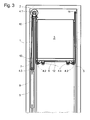
- Fig. 3 schematically shows a section through an installed in an elevator shaft 1 elevator system with the belt 12.
- the elevator system comprises a fixed in an elevator shaft 1 drive unit 2 with a drive wheel 4.1, guided on car guide rails 5 elevator car 3 with mounted below the cabin floor 6 guide wheels in the form of Cabin roller rollers 4.2, a counterweight guided on counterweight guide rails 7 8 with another guide wheel in the form of a counterweight roller 4.3, and the belt 12 for the elevator car 3 and the counterweight 8, which transmits the driving force from the drive wheel 4.1 of the drive unit 2 to the elevator car and the counterweight ,
- the belt 12 is attached at one of its ends below the drive wheel 4.1 to a first belt fixing point 10. From this, it extends down to the counterweight carrying roller 4.3, wraps around this and extends from this to the drive wheel 4.1, wraps around it and runs along the gegenimportants districten cabin wall down, wraps on both sides of the elevator car depending mounted below the elevator car 3 cabin roll 4.2 at 90 ° each and extends along the side facing away from the counterweight 8 cabin wall up to a second belt fixing point eleventh
- the plane of the drive wheel 4.1 can be arranged at right angles to the counterweight-side cabin wall and its vertical projection can be outside the vertical projection of the elevator car 3. It is therefore preferable that the drive wheel 4.1 has a small diameter, so that the distance between the left-side cabin wall and the opposite wall of the elevator shaft 1 can be as small as possible. In addition, a small drive wheel diameter allows the use of a gearless drive motor with relatively low drive torque as the drive unit. 2
- the drive wheel 4.1 and the counterweight support roller 4.3 are provided at their periphery with grooves which are formed substantially complementary to the ribs 15.1 of the belt 12.
- the ribs present on its traction surface lie in corresponding grooves of the pulley, thereby ensuring excellent belt guidance on these pulleys.
- the traction capability is improved by the between the grooves of the pulley serving as a pulley 4.1 and the ribs of the belt 12 wedge effect.
- the sliding surface of the belt 12 and the Kabinentragrollen 4.2 corresponding V-ribs.
- a third sub-belt made of polyurethane which has like the second sub-belt V-ribs.
Description
Die vorliegende Erfindung betrifft einen Riemen für eine Aufzuganlage, ein Herstellungsverfahren für einen solchen Riemen sowie eine Aufzuganlage mit einem solchen Riemen.The present invention relates to a belt for an elevator installation, to a manufacturing method for such a belt and to an elevator installation with such a belt.
Eine Aufzugsanlage umfasst eine Aufzugskabine und in der Regel ein Gegengewicht, die in einem Aufzugsschacht oder entlang freistehender Führungseinrichtungen bewegbar sind. Zum Erzeugen der Bewegung weist die Aufzugsanlage mindestens eine Antriebseinheit mit mindestens je einer Treibscheibe auf, die über einen oder mehrere Riemen die Aufzugkabine und das Gegengewicht tragen und/oder die erforderlichen Antriebskräfte auf diese übertragen.An elevator installation comprises an elevator cage and, as a rule, a counterweight, which are movable in an elevator shaft or along free-standing guide devices. To generate the movement, the elevator installation has at least one drive unit with at least one traction sheave each, which carries the elevator car and the counterweight via one or more belts and / or transmits the required drive forces thereto.
Dabei können die Aufzugkabine und das Gegengewicht über dieselben Riemen verbunden sein, die über die Treibscheibe(n) geführt sind und sowohl als Tragmittel als auch als Antriebsmittel wirken. Alternativ können die Aufzugkabine und das Gegengewicht auch über separate Tragriemen getragen und über separate Antriebsriemen angetrieben sein.In this case, the elevator car and the counterweight can be connected via the same belt, which are guided over the traction sheave (s) and act both as a support means and as a drive means. Alternatively, the elevator car and the counterweight can also be carried on separate straps and driven by separate drive belt.
Ein Riemen nach der vorliegenden Erfindung kann für jede der oben beschriebenen Funktionen eingesetzt werden, also als kombinierter Antriebs- und Tragriemen, als Tragriemen, der über mindestens ein Umlenkrad (Tragrolle) läuft und die Aufzugkabine mit dem Gegengewicht verbindet und beide trägt, oder als Antriebsriemen, der ausschließlich Antriebsfunktion hat und über mindestens eine Treibscheibe läuft.A belt according to the present invention can be used for any of the functions described above, that is, as a combined drive and carrying belt, as a carrying strap, which runs over at least one deflection wheel (carrying roller) and connects the elevator car with the counterweight and carries both, or as a drive belt , which has only drive function and at least one traction sheave.
Solche Riemen für Aufzuganlagen umfassen üblicherweise einen Riemenkörper aus einem Elastomer. Um die Zugkräfte zu übertragen, sind in dem Riemenkörper Zugträger in Form von Stahl- und/oder Kunststoff-Corden eingebettet. Die Corde können beispielsweise als Litzen oder Seile aus Stahldrähten bzw. Kunststofffasern ausgebildet sein. Sie sind vorteilhaft in der neutralen Faser des Riemenquerschnitts angeordnet, in der beim Umschlingen einer Riemenscheibe keine Zug- oder Druckspannungen auftreten.Such belts for elevator installations usually comprise a belt body made of an elastomer. In order to transmit the tensile forces, tension members in the form of steel and / or plastic cords are embedded in the belt body. The cords may be formed, for example, as strands or ropes made of steel wires or plastic fibers. They are advantageously arranged in the neutral fiber of the belt cross-section, in which no tensile or compressive stresses occur when looping around a belt pulley.
Aus der
Im Folgenden wird daher einheitlich von Treibrädern gesprochen, die herkömmliche Treibscheiben mit größeren Durchmessern, aber auch Treibscheiben mit relativ kleinen Durchmessern und insbesondere auch Abtriebswellen einer Antriebseinheit einer Aufzuganlage umfassen. Wo sich im Folgenden Aussagen sowohl auf Treibräder als auch auf Umlenkräder beziehen, werden diese gemeinsam als Riemenräder bezeichnet.The following is therefore uniformly spoken of driving wheels that include conventional traction sheaves with larger diameters, but also traction sheaves with relatively small diameters and in particular also output shafts of a drive unit of an elevator system. Where in the following statements relate to both drive wheels and pulleys, these are collectively referred to as pulleys.
Die Verwendung von Riemen mit dünnen Zugträgern und von Riemenräder mit geringen Durchmessern hat hohe Flächenpressungen zwischen den einzelnen Zugträgern und dem sie umgebenden Riemenkörper, wie auch hohe Druck- und Schubspannungen im Riemenkörper selbst zur Folge. Die Flächenpressung und/oder die genannten Spannungen im Riemenkörper können Werte erreichen, bei denen die Gefahr einer Schädigung des Riemenkörpers gegeben ist.The use of thin-gauge belts and small diameter pulleys results in high surface pressures between the individual tension members and the surrounding belt body, as well as high compressive and shear stresses in the belt body itself. The surface pressure and / or the stresses in the belt body can reach values at which there is a risk of damage to the belt body.
Diese Gefahr ist umso größer, je kleiner die Durchmesser der Zugträger werden, da infolge der Verkleinerung der kraftübertragenden Oberfläche bei gleicher Riemenbelastung die Flächenpressung wie auch die durch die Zugträger verursachten Spannungen im Riemenkörper steigen. Zusätzlich verstärkt sich mit abnehmendem Zugträgerdurchmesser die Kerbwirkung auf den Riemenkörper, der - in Hinblick auf die erforderliche Reibung zwischen Riemen und Treibrad, auf die erforderliche Übertragung der Zugkräfte vom Riemenkörper auf die Zugträger und auf die gewünschte Dämpfung von Schwingungen bzw. die Absorption von Stößen im Riemen - üblicherweise aus einem relativ weichen Elastomer hergestellt und damit besonders anfällig gegenüber den genannten Belastungen ist.This danger is greater, the smaller the diameter of the tension members are, as a result of the reduction of the force-transmitting surface with the same belt load the surface pressure as well as the tension caused by the tension in the belt body rise. In addition, with decreasing Zugträgerdurchmesser the notch effect on the belt body, which - in view of the required friction between the belt and drive wheel, the required transmission of tensile forces from the belt body to the Tensile and the desired damping of vibrations or the absorption of shock in the belt - usually made of a relatively soft elastomer and thus is particularly vulnerable to the above loads.
Da die Umlenkung um Riemenräder und die Übertragung der Zugkraft von einem Treibrad auf die einzelnen Zugträger unter Schub- und/oder Zugverformung des Riemenkörpers stattfindet, kann es aufgrund der oben dargestellten Effekte zu einer Schädigungen des Riemenkörpers in Form von Abrasion und/oder Zerrüttung des die Zugträger umgebenden Elastomers und/oder einem Einschneiden von Zugträgern in den Elastomer kommen.Since the deflection takes place around pulleys and the transmission of the tensile force of a drive wheel to the individual tension members under shear and / or tensile deformation of the belt body, it may due to the effects shown above to damage the belt body in the form of abrasion and / or dislocation of the Tensile surrounding elastomer and / or a cutting of tension members in the elastomer come.
Diese Gefahr besteht auch bei Riemen, wie sie aus der
Somit können solche Riemen nicht oder nur bedingt in sicherheitssensiblen Vorrichtungen wie einer Aufzuganlage eingesetzt werden, da hier das Gefahrenpotential bei einem Riemenbruch aufgrund der oben beschriebenen Schädigungen zu hoch ist. Gleichermaßen können solche Riemen nicht zur Übertragung hoher Kräfte eingesetzt werden, da sich dabei die Gefahr solcher Schädigungen vergrößert.Thus, such belts can not or only partially be used in safety-sensitive devices such as an elevator system, since the risk of a belt break due to the damage described above is too high. Likewise, such straps can not be used to transmit high forces as this increases the risk of such damage.
Weitere Riemen für Auf zugsanlagen sind in den Anmeldeschriften
Eine Aufgabe der vorliegenden Erfindung ist es daher, eine Aufzuganlage zu schaffen, bei der die Gefahr eines Versagens aufgrund eines Riemenbruches verringert ist. Eine weitere Aufgabe der vorliegenden Erfindung ist es, einen Riemen für eine solche Aufzuganlage zur Verfügung zu stellen, der auch höhere Kräfte übertragen kann. Eine weitere Aufgabe der vorliegenden Erfindung ist es, ein Verfahren zur Herstellung eines solchen Riemens anzugeben.An object of the present invention is therefore to provide an elevator system in which the risk of failure due to a belt breakage is reduced. Another object of the present invention is to provide a belt for such an elevator system, which can also transmit higher forces. Another object of the present invention is to provide a method of manufacturing such a belt.
Zur Lösung dieser Aufgaben sind ein Riemen gemäss den Merkmalen des Anspruchs 1, ein Herstellungsverfahren gemäss den Merkmalen des Anspruchs 11 bzw. eine Aufzuganlage gemäss den Merkmalen des Anspruchs 14 vorgesehen.To solve these objects, a belt according to the features of
Ein Riemen für eine Aufzuganlage nach einer Ausführung der vorliegenden Erfindung umfasst einen ersten Teilriemen aus einem ersten Material, in dem eine Zugträgeranordnung mit wenigstens einem Zugträger aus Stahldraht oder aus Stahldrahtlitzen bzw. Stahldrahtseilen angeordnet ist, und einen zweiten Teilriemen aus einem zweiten, vom ersten Material verschiedenen Material.A belt for an elevator system according to an embodiment of the present invention comprises a first part belt of a first material in which a tension member assembly having at least one tensile member of steel wire or steel wire strands or steel wire ropes is arranged, and a second part belt of a second, of the first material different material.
Erfindungsgemäß umfasst das erste Material wenigstens einen thermoplastischen Kunststoff. Bevorzugt handelt es sich bei diesem thermoplastischen Kunststoff um Polyamid (PA), Polyethylen (PE), Polycarbonat (PC) oder Polyvinylchlorid (PVC). Gleichermaßen kann das erste Material auch eine Mischung von zwei oder mehr thermoplastischen Kunststoffen, ein so genanntes Polyblend umfassen. Zur Verstärkung kann das erste Material auch Zusatzstoffe, insbesondere Fasern wie beispielsweise Kohle- oder Glasfasern enthalten. Gleichermaßen kann das erste Material ein Gewebe aus einem thermoplastischen Kunststoff umfassen.According to the invention, the first material comprises at least one thermoplastic. This thermoplastic material is preferably polyamide (PA), polyethylene (PE), polycarbonate (PC) or polyvinyl chloride (PVC). Likewise, the first material may also comprise a blend of two or more thermoplastics, a so-called polyblend. For reinforcement, the first material may also contain additives, in particular fibers such as carbon or glass fibers. Likewise, the first material may comprise a web of thermoplastic.
Durch die Anordnung der Zugträgeranordnung im ersten Teilriemen aus einem ersten thermoplastischen Material nimmt dieses hierfür besonders geeignete erste Material die normal und tangential zur Oberfläche der Zugträger wirkenden Kräfte auf und überträgt diese, im Wesentlichen über die gesamte Verbindungsfläche verteilt, auf den zweiten Teilriemen. Damit erhöht sich die Fläche, über die die Kräfte aus den Zugträgern in den zweiten Teilriemen eingeleitet werden, so dass sich die auf diesen wirkenden Spannungen, insbesondere Druck- und Schubspannungen verringern. Zugleich verringert sich die Kerbwirkung auf den zweiten Teilriemen.By arranging the tension member assembly in the first sub-belt of a first thermoplastic material takes this particular suitable first material on the normal and tangential to the surface of the tension members acting forces and transmits them, distributed substantially over the entire connecting surface, on the second sub-belt. This increases the area over which the forces are introduced from the tension members in the second belt, so that reduce the stresses acting on these, in particular compressive and shear stresses. At the same time, the notch effect on the second part belt is reduced.
Vorteilhafterweise wird es damit möglich, das zweite Material des zweiten Teilriemens in Hinblick auf dessen Funktion, insbesondere den reibschlüssigen Kontakt mit einem Treibrad, die Dämpfung von Schwingungen und Stößen und/oder die zur Umschlingung von Riemenrädern erforderliche Elastizität zu wählen. Gleichzeitig können die von den Zugträgern zu übertragenden Kräfte und damit die zulässige Riemenbelastung erhöht werden, da die von den Zugträgern in dem Riemen erzeugten Flächenpressungen und Spannungen zunächst von dem ersten Teilriemen aufgenommen werden, dessen erstes Material in Hinblick auf die vorliegende Beanspruchung geeignet gewählt werden kann. Im ersten Teilriemen verteilen sich die von den Zugträgern auf den Riemenkörper übertragenen Belastungen, so dass die auf den zweiten Teilriemen an dessen Verbindungsfläche zum ersten Teilriemen einwirkenden maximalen Flächenpressungen und Druckspannungen nur noch reduziert auftreten.Advantageously, it is thus possible to select the second material of the second sub-belt with regard to its function, in particular the frictional contact with a drive wheel, the damping of vibrations and shocks and / or the elasticity required for wrapping belt pulleys. At the same time, the forces to be transmitted by the tension members and thus the permissible belt load can be increased, since the surface pressures and stresses generated by the tension members in the belt are first absorbed by the first part belt whose first material can be suitably selected with regard to the present stress , In the first sub-belt distributed by the tension members on the belt body loads distributed so that on the second belt at the connecting surface to the first belt acting maximum surface pressures and compressive stresses occur only reduced.
Vorzugsweise wird der erste Teilriemen verhältnismäßig dünn ausgebildet, so dass er trotz seiner höheren Härte die Biegeelastizität des Riemens nicht wesentlich beeinträchtigt. Vorteilhafterweise beträgt dementsprechend die Dicke des ersten Teilriemens höchstens 60%, bevorzugt höchstens 40 % und besonders bevorzugt höchstens 30 % der Gesamtdicke des Riemens.Preferably, the first partial belt is made relatively thin, so that it does not significantly affect the bending elasticity of the belt despite its higher hardness. Advantageously, accordingly, the thickness of the first part belt is at most 60%, preferably at most 40% and particularly preferably at most 30% of the total thickness of the belt.
Um zu gewährleisten, dass das erste Material, aus dem der erste Teilriemen besteht, die aus der Belastung der Zugträger resultierenden relativ hohen lokalen Flächenpressungen, Druck- und Schubspannungen langfristig erträgt, weist das erste Material vorzugsweise die folgenden Materialkennwerte (bei Raumtemperatur) auf:
- Mindest-Streckspannung nach DIN 53455 bzw. ISO 527: 45 N/mm2
- Mindest-Reißdehnung nach DIN 53455 bzw. ISO 527: 45 %.
- Mindest-Kugeldruckhärte nach DIN 53456 bzw. ISO 2039 (H358/30s): 30 N/mm2
bevorzugt: 50 N/mm2
besonders bevorzugt: 70 N/mm2
- Minimum yield stress according to DIN 53455 or ISO 527: 45 N / mm 2
- Minimum elongation at break according to DIN 53455 or ISO 527: 45%.
- Minimum ball hardness according to DIN 53456 or ISO 2039 (H358 / 30s): 30 N / mm 2
preferably: 50 N / mm 2
particularly preferred: 70 N / mm 2
In Materialien mit diesen Kennwerten schneiden die Zugträger auch unter hoher Belastung nicht oder nur wenig ein. Sie ertragen auch die auftretenden Druck- und/oder Schubspannungen, ohne unzulässig hohe Deformationen, Abrasion oder Zerrüttung zu zeigen.In materials with these characteristics, the tension members do not cut or only slightly under high load. They also endure the compressive and / or shear stresses that occur, without showing inadmissibly high deformations, abrasion or disruption.
Vorzugsweise ist auch der Reibwert des ersten Materials, das auch den der Traktionsfläche abgewandten Riemenrücken bildet, relativ gering. Dadurch verringert sich beim Umschlingen von Umlenkrädern ohne Längsrillen die zwischen den Umlenkrädern und dem Riemen auftretende Reibkraft, die zum seitlichen Führen des Riemens auf dem Umlenkrad zu überwinden ist. In der Folge werden die schädliche seitliche Reibbelastung des Riemens - beispielsweise durch Führungsbordscheiben der Umlenkräder - und damit auch die erforderliche Antriebsleistung der Aufzugsanlage reduziert und die Lebensdauer des Riemens erhöht. In einer vorteilhaften Ausführung kann ein Riemen nach der vorliegenden Erfindung hierzu eine Beschichtung der Riemenrückseite aus einem Material aufweisen, das einen niedrigeren Reibwert und/oder eine höhere Abriebfestigkeit als das erste Material aufweist.Preferably, the coefficient of friction of the first material, which also forms the belt back facing away from the traction surface, is relatively small. As a result, the friction force occurring between the deflecting wheels and the belt, which is to be overcome for laterally guiding the belt on the deflecting wheel, is reduced during the wrapping of deflecting wheels without longitudinal grooves. As a result, the harmful lateral frictional load of the belt - for example, by Führungsbordscheiben the deflecting wheels - and thus reduces the required drive power of the elevator system and increases the life of the belt. In an advantageous embodiment, a belt according to the present invention for this purpose, a coating of the belt back of a material having a lower coefficient of friction and / or a higher abrasion resistance than the first material.
Die Zugträgeranordnung umfasst wenigstens einen, bevorzugt jedoch mehrere, im Wesentlichen parallele Zugträger, die insbesondere in Längsrichtung des Riemens angeordnet sein können. Die erfindungsgemäße Anordnung der Zugträger in dem stabilen ersten Teilriemen erleichtert deren lagerichtige Anordnung während des Herstellungsvorgangs, da die Zugträger beim Aufbringen des zweiten Materials bereits im ersten Material fixiert sind. Die Zugträger können als Einfachdraht ausgebildet oder, bevorzugt, aus Litzen oder Seilen aufgebaut sein, wobei die Litzen oder Seile aus Stahldrähten hergestellt sind. In einer besonders bevorzugten Ausführung sind die Zugträger der Zugträgeranordnung in oder in der Nähe der neutralen Faser des gesamten Riemens angeordnet, in der bei der Umlenkung um ein Riemenrad, insbesondere ein Treibrad, keine Zug- oder Druckspannungen auftreten.The Zugträgeranordnung comprises at least one, but preferably a plurality of substantially parallel tension members, which may be arranged in particular in the longitudinal direction of the belt. The inventive arrangement of the tension members in the stable first part belt facilitates their positionally correct arrangement during the manufacturing process, since the tension members are already fixed in the first material when the second material is applied. The tension members may be formed as a single wire or, preferably, constructed of strands or ropes, the strands or ropes being made of steel wires. In a particularly preferred embodiment, the tension members of the tension member arrangement are arranged in or in the vicinity of the neutral fiber of the entire belt in which no tensile or compressive stresses occur during the deflection around a pulley, in particular a drive wheel.
Vorzugsweise ist der zweite Teilriemen des Riemens zum Zusammenwirken mit einem Treibrad der Aufzuganlage vorgesehen. In einer vorteilhaften Ausführung weist er hierzu eine Traktionsfläche auf, in der wenigstens eine Keilrippe ausgebildet ist, die in eine korrespondierende, im Wesentlichen komplementäre Rille in der Lauffläche des Treibrades eingreift. Zur Erhöhung der Traktionsfähigkeit bzw. zur Verbesserung der seitlichen Führung des Riemens auf den Riemenrädern können bevorzugt mehrere Keilrippen nebeneinander ausgebildet sein. Diese müssen nicht zwingend miteinander verbunden sein. Getrennte, auf dem ersten Teilriemen angeordnete Keilrippen des zweiten Teilriemen können Lageabweichungen der einzelnen Rillen eines Treibrades zueinander vorteilhaft ausgleichen. Andererseits vergrößert ein wenigstens dünner Verbindungssteg, der sich zwischen benachbarten Rippen auf der Verbindungsfläche zum ersten Teilriemen erstreckt, vorteilhaft diese Verbindungsfläche und damit die Festigkeit der Verbindung zwischen dem ersten und dem zweiten Teilriemen.Preferably, the second belt part of the belt for cooperation with a drive wheel of the elevator system is provided. In an advantageous embodiment, it has for this purpose a traction surface, in which at least one V-rib is formed, which engages in a corresponding, substantially complementary groove in the running surface of the drive wheel. In order to increase the traction capability or to improve the lateral guidance of the belt on the pulleys, a plurality of V-ribs may preferably be formed next to each other. These do not necessarily have to be connected with each other. Separate, arranged on the first sub-belt V-ribs of the second sub-belt can compensate for positional deviations of the individual grooves of a drive wheel to each other advantageous. On the other hand, an at least thin connecting web, which extends between adjacent ribs on the connecting surface to the first part belt, advantageously increases this connecting surface and thus the strength of the connection between the first and the second part belt.
In einer vorteilhaften Ausführung weist eine Keilrippe einen im Wesentlichen trapezförmigen Querschnitt mit einem zwischen ihren beiden Flanken gemessenen Flankenwinkel von 60° bis 120° auf. Es sind auch andere Querschnittsformen, beispielsweise dreieckige Querschnitte, möglich.In an advantageous embodiment, a V-rib has a substantially trapezoidal cross-section with a flank angle of 60 ° to 120 ° measured between its two flanks. There are also other cross-sectional shapes, such as triangular cross-sections, possible.
In einer vorteilhaften Ausführung weist die Traktionsfläche des Riemens eine Beschichtung auf, die mit der Lauffläche eines Treibrades der Aufzuganlage einen definierten Reibwert aufweist. Dieser Reibwert kann höher als derjenige des zweiten Materials sein, um beispielsweise die Traktionsfähigkeit zu verbessern. Alternativ kann er auch niedriger als derjenige des zweiten Materials sein. Dies reduziert einerseits den Verschleiß an der Traktionsfläche und kann insbesondere bei einer Traktionsfläche, auf der eine oder mehrere Keilrippen ausgebildet sind, die Gefahr eines Verklemmens der Keilrippen in den Rillen eines Riemenrades eliminieren.In an advantageous embodiment, the traction surface of the belt has a coating which has a defined coefficient of friction with the running surface of a drive wheel of the elevator installation. This coefficient of friction may be higher than that of the second material, for example, to improve traction. Alternatively, it may be lower than that of the second material. This reduces on the one hand the wear on the traction surface and can eliminate the risk of jamming of the V-ribs in the grooves of a pulley, especially in a traction surface on which one or more V-ribs are formed.
Das zweite Material für den zweiten Teilriemen umfasst bevorzugt ein Elastomer, insbesondere Polyurethan, Polychloropren oder Ethylen-Propylen-Dien-Kautschuk oder eine Mischung aus zwei oder mehreren Elastomeren. Ein derartiger elastomerer zweiter Teilriemen ist ausreichend flexibel zur Umschlingung von Riemenrädern mit geringen Durchmessern. Gleichzeitig dämpft ein solches zweites Material in bekannter Weise vorteilhaft Schwingungen und Stöße im Riemen. Zugleich erträgt es beim Zusammenwirken mit einer Lauffläche eines Treibrades die zur Übertragung der Zugkräfte in den Riemen auftretende Schubverformung aufgrund seiner elastischen Eigenschaften.The second material for the second part belt preferably comprises an elastomer, in particular polyurethane, polychloroprene or ethylene-propylene-diene rubber or a mixture of two or more elastomers. Such an elastomeric second sub-belt is sufficiently flexible for wrapping pulleys with small diameters. At the same time dampens such a second material in a known manner advantageous vibrations and shocks in the belt. At the same time it bears when interacting with a running surface of a drive wheel occurring for the transmission of tensile forces in the belt shear deformation due to its elastic properties.
Somit kann für den zweiten Teilriemen ein relativ weiches zweites Material gewählt werden, dessen Härte bei Raumtemperatur vorteilhaft weniger als 95 Shore (A), bevorzugt weniger als 90 Shore (A) und besonders bevorzugt weniger als 85 Shore (A) beträgt, da erfindungsgemäß die hohen lokalen Flächenpressungen der einzelnen Zugträger vom ersten, härteren Material aufgenommen und als homogenere und geringere Flächenpressung über die Verbindungsfläche auf das zweite Material übertragen werden.Thus, for the second sub-belt, a relatively soft second material can be selected, whose hardness at room temperature is advantageously less than 95 Shore (A), preferably less than 90 Shore (A) and particularly preferably less than 85 Shore (A), since according to the invention high local surface pressures of the individual tensile carriers are absorbed by the first, harder material and transferred to the second material as a more homogeneous and lower surface pressure via the connecting surface.
Ein Riemen nach einer Ausführung der vorliegenden Erfindung wird bevorzugt in den folgenden Schritten hergestellt. Zunächst wird der erste Teilriemen aus dem ersten Material hergestellt. Vorteilhaft geschieht dies durch Extrudieren des thermoplastischen Kunststoffes, was eine gleichmäßige, kostengünstige und endlose Herstellung ermöglicht.A belt according to an embodiment of the present invention is preferably manufactured in the following steps. First, the first partial belt is made of the first material. This is advantageously done by extruding the thermoplastic material, which allows a uniform, inexpensive and endless production.
Bereits beim Urformen (Extrusionsvorgang) des ersten Teilriemens können die Zugträger im ersten Teilriemen angeordnet werden, wozu die einzelnen Zugträger während des Extrusionsvorganges dem entstehenden ersten Teilriemen derart zugeführt werden, dass sie mindestens auf der dem zweiten Teilriemen zugewandten Seite vollständig von dem ersten Material umhüllt sind.Already during prototyping (extrusion process) of the first part belt, the tension members can be arranged in the first part belt, for which purpose the individual tension members are fed to the resulting first part belt during the extrusion process so that they are completely enveloped by the first material at least on the side facing the second part belt ,
Bevorzugt sind die Zugträger vollständig von erstem Material umhüllt. Zur Lösung der erfindungsgemäßen Aufgabe ist es jedoch ausreichend, wenn die dem zweiten Teilriemen zugewandte Seite der Zugträger von diesem durch das erste Material getrennt ist. In einer weiteren Ausführungsform der vorliegenden Erfindung können daher zunächst der erste Teilriemen hergestellt und anschließend die einzelnen Zugträger auf dessen der Verbindungsfläche zum zweiten Teilriemen abgewandten Seite angeordnet werden. Hierzu kann der erste Teilriemen auf dieser abgewandten Seite vorteilhaft Rillen zur lagerichtigen Positionierung der Zugträger aufweisen. Die Fixierung der Zugträger in den Rillen des ersten Teilriemen kann dabei mittels thermischer Nachbehandlung des thermoplastischen Materials oder durch Zugabe eines Klebstoffs erfolgen. Die Zugträger, die im Bereich der dem zweiten Teilriemen abgewandten Seite des ersten Teilriemens angeordnet sind, können aber auch am zweiten Teilriemen durch einen dritten Teilriemen fixiert werden, der mit der genannten Seite des ersten Teilriemens, beispielsweise durch Kleben und/oder Aufextrudieren, derart verbunden wird, dass die Zugträger zwischen erstem und drittem Teilriemen fixiert sind.Preferably, the tension members are completely enveloped by the first material. However, to achieve the object according to the invention, it is sufficient if the side of the tension member facing the second partial belt is separated therefrom by the first material. In a further embodiment of the present invention, therefore, first the first partial belt can be produced and then the individual tensile carriers can be arranged on the side facing away from the connecting surface to the second partial belt. For this purpose, the first part of belt on this side facing away advantageous grooves for the correct position positioning of the tension members. The fixation of the tension members in the grooves of the first belt can be done by means of thermal treatment of the thermoplastic material or by adding an adhesive. The tension members, which are arranged in the region of the second belt side facing away from the first belt, but can also be fixed to the second belt by a third sub-belt connected to said side of the first belt part, for example by gluing and / or extrusion is that the tension members are fixed between the first and third sub-belt.
In einem weiteren Schritt wird der zweiten Teilriemen aus dem zweiten Material hergestellt und mit dem ersten Teilriemen fest verbunden. Dies kann bevorzugt durch Aufextrudieren des zweiten auf den ersten Teilriemen erfolgen. Dabei können vorteilhafterweise auch die Keilrippen der Traktionsfläche des zweiten Teilriemens ausgebildet werden.In a further step, the second sub-belt is made of the second material and firmly connected to the first sub-belt. This can preferably be done by extruding the second onto the first partial belt. In this case, advantageously, the V-ribs of the traction surface of the second sub-belt can be formed.
Gleichermaßen kann der zweite Teilriemen auch mit dem ersten Teilriemen verklebt werden. In einer besonders bevorzugten Ausführung enthält das zweite Material hierzu einen Klebstoff, der beim Aufextrudieren auf den ersten Teilriemen durch thermisches Verkleben eine feste Verbindung zu diesem schafft.Similarly, the second belt can also be bonded to the first belt part. In a particularly preferred embodiment, the second material for this purpose contains an adhesive which, when extruded onto the first sub-belt by thermal bonding, creates a firm connection thereto.
Die vorteilhafte Beschichtung der Traktionsfläche des zweiten Teilriemens kann während seiner Herstellung oder im Anschluss daran aufgebracht werden. So kann ein Kunstfasergewebe, eine Schicht aus einem anderen Elastomer, eine Beflockungsschicht und/oder eine Thermoplastschicht, die beispielsweise Polyamid enthält, während des Extrudierens des zweiten Teilriemens auf seiner Traktionsfläche angeordnet werden, wobei sich die Beschichtung vorteilhaft fest mit dem noch formbaren zweiten Material verbindet.The advantageous coating of the traction surface of the second sub-belt can be applied during its manufacture or subsequently. Thus, a synthetic fiber fabric, a layer of another elastomer, a flocking layer and / or a thermoplastic layer containing, for example, polyamide can be arranged on the surface of its traction surface during the extrusion of the second part belt, wherein the coating advantageously bonds firmly to the still mouldable second material ,
Eine Aufzuganlage nach der vorliegenden Erfindung umfasst eine Aufzugkabine, eine Antriebseinheit mit wenigstens einem Treibrad und einer Riemenanordnung mit wenigstens einem Riemen nach einer Ausführung der vorliegenden Erfindung. Vorteilhaft kann die Riemenanordnung auch mehrere Riemen nach einer oder verschiedenen Ausführungen der vorliegenden Erfindung umfassen, die, beispielsweise formschlüssig, fest oder lösbar miteinander verbunden sein können. Dies ermöglicht es, eine relativ breite Riemenanordnung aus mehreren schmalen, leichter zu handhabenden Riemen vor Ort zusammenzusetzen. Das oder die Treibräder weisen in einer bevorzugten Ausführung ein im Wesentlichen zur Traktionsfläche des zweiten Riemens komplementäres Keilrippenprofil auf.An elevator installation according to the present invention comprises an elevator car, a drive unit with at least one drive wheel and a belt arrangement with at least one belt according to an embodiment of the present invention. Advantageously, the belt assembly may also comprise a plurality of belts according to one or more embodiments of the present invention, which may be fixedly or detachably connected to each other, for example by positive engagement. This makes it possible to assemble a relatively wide belt assembly of several narrow, easier-to-use straps on site. In one preferred embodiment, the drive wheel or wheels have a V-rib profile that is substantially complementary to the traction surface of the second belt.
Weitere Aufgaben, Merkmale und Vorteile ergeben sich aus den Unteransprüchen und den nachfolgend beschriebenen Ausführungsbeispiele. Hierzu zeigt:
- Fig. 1
- einen Querschnitt durch einen Riemen nach einer Ausführung der vorliegenden Erfindung; und
- Fig. 2
- einen zu einer Aufzugskabinenfront parallelen Schnitt durch eine Aufzugsanla- ge nach einer Ausführung der vorliegenden Erfindung.
- Fig. 1
- a cross-section through a belt according to an embodiment of the present invention; and
- Fig. 2
- a parallel to an elevator car front section through an elevator system according to an embodiment of the present invention.
In einer nicht dargestellten Ausführung ist die Traktionsfläche mit einer dünnen Beschichtung aus Polyamid versehen, um den Reibwert zu senken. Aufgrund der Keilrippen 15.1 ergibt sich trotzdem eine ausreichende Traktionsfähigkeit, wobei die Polyamid-Beschichtung vorteilhaft den Verschleiß der Traktionsfläche vermindert und die Gefahr eines Verklemmens des Riemens 12 in dem Treibrad 4.1 reduziert.In one embodiment, not shown, the traction surface is provided with a thin coating of polyamide to lower the coefficient of friction. Due to the V-ribs 15.1 still gives sufficient traction, wherein the polyamide coating advantageously reduces the wear of the traction surface and reduces the risk of jamming of the
Die Größenverhältnisse zwischen erstem und zweitem Teilriemen und den Zugträgern sind in
In
Der Riemen 12 ist an einem seiner Enden unterhalb des Treibrades 4.1 an einem ersten Riemenfixpunkt 10 befestigt. Von diesem aus erstreckt er sich abwärts bis zu der Gegengewichtstragrolle 4.3, umschlingt diese und erstreckt sich von dieser aus zum Treibrad 4.1, umschlingt diese und verläuft entlang der gegengewichtsseitigen Kabinenwand abwärts, umschlingt auf beiden Seiten der Aufzugskabine je eine unterhalb der Aufzugskabine 3 angebrachte Kabinentragrolle 4.2 um je 90° und verläuft entlang der dem Gegengewicht 8 abgewandten Kabinenwand aufwärts zu einem zweiten Riemenfixpunkt 11.The
Die Ebene des Treibrades 4.1 kann rechtwinklig zur gegengewichtsseitigen Kabinenwand angeordnet sein und ihre Vertikalprojektion kann außerhalb der Vertikalprojektion der Aufzugskabine 3 liegen. Es ist daher zu bevorzugen, dass das Treibrad 4.1 einen geringen Durchmesser aufweist, damit der Abstand zwischen der linksseitigen Kabinenwand und der dieser gegenüber liegenden Wand des Aufzugsschachts 1 möglichst klein sein kann. Außerdem ermöglicht ein geringer Treibraddurchmesser die Verwendung eines getriebelosen Antriebsmotors mit relativ geringem Antriebsdrehmoment als Antriebseinheit 2.The plane of the drive wheel 4.1 can be arranged at right angles to the counterweight-side cabin wall and its vertical projection can be outside the vertical projection of the
Das Treibrad 4.1 und die Gegengewichtstragrolle 4.3 sind an ihrer Peripherie mit Rillen versehen, die im Wesentlichen komplementär zu den Rippen 15.1 des Riemens 12 geformt sind. Wo der Riemen 12 eines der Riemenräder 4.1 oder 4.3 umschlingt, liegen die auf seiner Traktionsfläche vorhandenen Rippen in korrespondierenden Rillen des Riemenrades, wodurch eine ausgezeichnete Führung des Riemens auf diesen Riemenrädern gewährleistet ist. Außerdem wird durch die zwischen den Rillen des als Treibrad dienenden Riemenrades 4.1 und den Rippen des Riemens 12 entstehende Keilwirkung die Traktionsfähigkeit verbessert.The drive wheel 4.1 and the counterweight support roller 4.3 are provided at their periphery with grooves which are formed substantially complementary to the ribs 15.1 of the
In einer nicht dargestellten weiteren Ausführungsform weisen auch die Gleitfläche des Riemens 12 und die Kabinentragrollen 4.2 korrespondierende Keilrippen auf. Hierzu ist bei der nicht dargestellten weiteren Ausführungsform auf der dem zweiten Teilriemen 15 abgewandten Seite des ersten Teilriemens 13 ein dritter Teilriemen aus Polyurethan angeordnet, der wie der zweite Teilriemen Keilrippen aufweist. Bei der Umschlingung der Kabinentragrollen 4.2 unterhalb der Aufzugskabine 3 ist daher im Gegensatz zu herkömmlichen Aufzuganlagen auch eine seitliche Führung zwischen den Kabinentragrollen 4.2 und dem Riemen 12 gegeben, da der Riemen auch Rippen auf seiner den Kabinentragrollen 4.2 zugewandten Seite aufweist. Um die Seitenführung des Riemens noch weiter zu verbessern, sind am Kabinenboden 6 zwei mit Rillen versehene Führungsrollen 4.4 angebracht, deren Rillen mit den Rippen des Riemens 12 als Seitenführung zusammenwirken.In a further embodiment, not shown, the sliding surface of the
Claims (14)
- Belt (12; 22) for a lift installation, which comprises:- a first part belt (13) of a first material, wherein the first material is a thermoplastic plastics material or contains a thermoplastic plastics material and wherein the first material contains polyamide (PA), polyethylene (PE), polycarbonate (PC) or polyvinylchloride (PVC);- a tensile carrier arrangement with at least one tensile carrier (14), which is arranged in the first part belt, wherein the tensile carrier (14) consists of a single steel wire or of a steel wire strand or a steel wire cable; and- a second part belt (15; 25) of a second material, wherein the second material comprises an elastomer and wherein the second material comprises polyurethane (PU) and/or polychloroprene (CR) and/or ethylene-propylene-diene rubber (EPDM).wherein the tensile carriers in the finished belt are arranged in the neutral axis of the overall belt.
- Belt (12; 22) according to claim 1, wherein the first material is selected from one of the following material groups;- polyblend, which contains one of the said materials or- fabric consisting of one of the said materials.
- Belt (12; 22) according to claim 1 or 2, wherein the first material has at room temperature a minimum yield stress according to DIN 53455 or ISO 527 of 45 N/mm2.
- Belt (12; 22) according to any one of the preceding claims, wherein the first material has at room temperature a minimum elongation at tear according to DIN 53455 or ISO 527 of 45%.
- Belt (12; 22) according to any one of the preceding claims, wherein the first material has at room temperature a minimum indentation hardness according to DIN 53456 or ISO 2039 (H358/30s) of 30 N/mm2, preferably 50 N/mm2, particularly preferably of 70 N/mm2.
- Belt (12; 22) according to any one of the preceding claims, wherein the thickness of the first part belt (13; 23) is at most 60%, preferably at most 40% and particularly preferably at most 30% of the total thickness of the belt.
- Belt (12; 22) according to any one of the preceding claims, wherein the second part belt (15; 25) has a traction surface for co-operation with a drive wheel of the lift installation, in which at least one wedge rib (15.1; 25.1) is formed.
- Belt (12; 22) according to any one of the preceding claims, wherein the traction surface of the second part belt (15) has for co-operation with a drive wheel (4.1) of the lift installation a coating which has a defined coefficient of friction relative to the running surface of the drive wheel (4.1), particularly a higher or lower coefficient of friction than the second material.
- Belt (12; 22) according to any one of the preceding claims, wherein the second material has at room temperature a hardness of less than 95 Shore (A), preferably of less than 90 Shore (A) and particularly preferably a hardness of less than 85 Shore (A).
- Belt (22) according to any one of the preceding claims, wherein- at least two wedge ribs (25.1) each have a trapezium-shaped or wedge-shaped contact section (28) and a substantially rectangular base section (29),- the rectangular base sections (29) are arranged between the contact sections (28) and the first part belt (23) and comprise at least 20% of the height of the second part belt (25) and- the base sections (29) are completely separated from one another by intermediate spaces (26).
- Production method for a belt (12; 22) according to one of claims 1 to 10, comprising the steps:producing a first part belt (13) with tensile carriers (14) embedded therein from a first material,according to claim 1, wherein the production is carried out particularly by extrusion;producing a second part belt (15) from a second material according to claim 1; andconnecting the first part belt and second part belt, wherein the tensile carriers are so positioned in the finished belt that they are arranged in the neutral axis of the overall belt.
- Production method according to claim 11, wherein the second part belt is extruded onto the first part belt and/or thermally glued thereto.
- Production method according to claim 11 or 12, wherein the first material is so selected in its properties and its cover thickness over the tensile carriers that it accepts local area pressures of the tensile carriers and transmits a more homogeneous and smaller area pressure via a connecting surface to the second material.
- Lift installation with a lift cage (3), a drive unit (2) with a drive wheel (4.1) and a belt arrangement with at least one belt (12; 22) according to any one of claims 1 to 10.
Priority Applications (1)
| Application Number | Priority Date | Filing Date | Title |
|---|---|---|---|
| EP09175749A EP2154097B1 (en) | 2006-08-11 | 2007-08-08 | Lift belt for a lift system and method for manufacturing such a lift belt |
Applications Claiming Priority (3)
| Application Number | Priority Date | Filing Date | Title |
|---|---|---|---|
| EP06118819 | 2006-08-11 | ||
| EP09175749A EP2154097B1 (en) | 2006-08-11 | 2007-08-08 | Lift belt for a lift system and method for manufacturing such a lift belt |
| EP07113974A EP1886796B1 (en) | 2006-08-11 | 2007-08-08 | Belt for such a lift facility and lift facility with a such belt |
Related Parent Applications (2)
| Application Number | Title | Priority Date | Filing Date |
|---|---|---|---|
| EP07113974A Division EP1886796B1 (en) | 2006-08-11 | 2007-08-08 | Belt for such a lift facility and lift facility with a such belt |
| EP07113974.5 Division | 2007-08-08 |
Publications (2)
| Publication Number | Publication Date |
|---|---|
| EP2154097A1 EP2154097A1 (en) | 2010-02-17 |
| EP2154097B1 true EP2154097B1 (en) | 2011-09-28 |
Family
ID=37714449
Family Applications (2)
| Application Number | Title | Priority Date | Filing Date |
|---|---|---|---|
| EP09175749A Not-in-force EP2154097B1 (en) | 2006-08-11 | 2007-08-08 | Lift belt for a lift system and method for manufacturing such a lift belt |
| EP07113974A Not-in-force EP1886796B1 (en) | 2006-08-11 | 2007-08-08 | Belt for such a lift facility and lift facility with a such belt |
Family Applications After (1)
| Application Number | Title | Priority Date | Filing Date |
|---|---|---|---|
| EP07113974A Not-in-force EP1886796B1 (en) | 2006-08-11 | 2007-08-08 | Belt for such a lift facility and lift facility with a such belt |
Country Status (19)
| Country | Link |
|---|---|
| EP (2) | EP2154097B1 (en) |
| JP (1) | JP2008069008A (en) |
| KR (1) | KR20080014705A (en) |
| CN (1) | CN101122097B (en) |
| AR (1) | AR062349A1 (en) |
| AT (2) | ATE452745T1 (en) |
| AU (1) | AU2007205738A1 (en) |
| BR (1) | BRPI0703706A2 (en) |
| CA (1) | CA2596716A1 (en) |
| DE (1) | DE502007002382D1 (en) |
| DK (1) | DK1886796T3 (en) |
| ES (2) | ES2339885T3 (en) |
| MX (1) | MX2007009685A (en) |
| NO (1) | NO20074120L (en) |
| PL (1) | PL1886796T3 (en) |
| PT (1) | PT1886796E (en) |
| RU (1) | RU2448032C2 (en) |
| TW (1) | TW200829504A (en) |
| ZA (1) | ZA200706598B (en) |
Cited By (1)
| Publication number | Priority date | Publication date | Assignee | Title |
|---|---|---|---|---|
| US11214465B2 (en) | 2016-12-16 | 2022-01-04 | Otis Elevator Company | Elevator system suspension member |
Families Citing this family (21)
| Publication number | Priority date | Publication date | Assignee | Title |
|---|---|---|---|---|
| EP2733259B1 (en) * | 2008-08-15 | 2020-12-09 | Otis Elevator Company | Cord and polymer jacket assembly having a flame retardant in the polymer jacket material |
| CN102264623B (en) * | 2008-12-22 | 2013-09-04 | 因温特奥股份公司 | Elevator support means, manufacturing method for said support means and elevator system comprising said elevator support means |
| CN101875467B (en) * | 2010-03-29 | 2012-05-23 | 江南嘉捷电梯股份有限公司 | Traction belt for elevators |
| EP2940201B1 (en) | 2010-05-13 | 2018-07-04 | Otis Elevator Company | Method of making a woven fabric having a desired spacing between tension members |
| KR101445652B1 (en) * | 2010-09-20 | 2014-09-29 | 오티스 엘리베이터 컴파니 | Elevator suspension and/or driving assembly having at least one traction surface comprising exposed weave fibers |
| CN102002872B (en) * | 2010-10-28 | 2013-06-05 | 西子电梯集团有限公司 | Fiber-woven flexible composite traction belt for elevator and manufacturing method thereof |
| CN103328368B (en) * | 2011-01-21 | 2016-09-28 | 奥的斯电梯公司 | For reducing the system and method for the noise of band |
| CN102304863B (en) * | 2011-08-02 | 2014-01-15 | 宁波谷达机电有限公司 | Elevator traction belt and manufacture method thereof |
| CN102359543A (en) * | 2011-10-20 | 2012-02-22 | 无锡通用钢绳有限公司 | Flat steel strip for elevator |
| FI123534B (en) * | 2012-02-13 | 2013-06-28 | Kone Corp | Lifting rope, lift and method of rope manufacture |
| EP2799217B1 (en) * | 2013-04-30 | 2015-06-03 | Kone Corporation | A method for manufacturing a rope, a rope and an elevator |
| CN106115436B (en) | 2015-05-07 | 2020-06-30 | 奥的斯电梯公司 | Refractory coated steel strip |
| WO2017155943A1 (en) | 2016-03-09 | 2017-09-14 | Otis Elevator Company | Reinforced fabric elevator belt with improved internal wear resistance |
| DE102016209633A1 (en) * | 2016-06-02 | 2017-12-07 | Contitech Antriebssysteme Gmbh | V-belt and method for its manufacture |
| US10941021B2 (en) * | 2017-08-28 | 2021-03-09 | Otis Elevator Company | Sheave for belt with profile tracking features |
| US11820628B2 (en) | 2017-10-17 | 2023-11-21 | Inventio Ag | Elevator system comprising deflecting elements having different groove geometries |
| DE102018202454A1 (en) * | 2018-02-19 | 2019-08-22 | Contitech Antriebssysteme Gmbh | Belt drive and pull or carrying strap for it |
| US10882719B2 (en) * | 2018-03-29 | 2021-01-05 | Thyssenkrupp Elevator Ag | Composite elevator belt |
| CN109132789A (en) * | 2018-10-30 | 2019-01-04 | 艾艾精密工业输送系统(上海)股份有限公司 | A kind of composite elevator drawing belt |
| DE102019207434A1 (en) * | 2019-05-21 | 2020-11-26 | Contitech Antriebssysteme Gmbh | Timing belt |
| DE102019217625A1 (en) * | 2019-11-15 | 2021-05-20 | Contitech Antriebssysteme Gmbh | Elevator belt with cords made of coated strands |
Family Cites Families (23)
| Publication number | Priority date | Publication date | Assignee | Title |
|---|---|---|---|---|
| DE1141443B (en) * | 1957-05-29 | 1962-12-20 | Dayco Corp | Process for the production of multiple V-belts |
| US3948113A (en) * | 1974-11-29 | 1976-04-06 | The Goodyear Tire & Rubber Company | Multi-ribbed power transmission belt and method of making said belt |
| US4177688A (en) * | 1978-02-08 | 1979-12-11 | Dayco Corporation | Endless power transmission belt and method for making same |
| DE2905362A1 (en) * | 1979-02-13 | 1980-08-14 | Dayco Corp | Reinforced ribbed belt mfr. - by pressing a belt blank against a grooved drum and vulcanising it in that position |
| JPS5667348A (en) * | 1979-11-08 | 1981-06-06 | Mitsuboshi Belting Ltd | Rubber composition |
| DE3527640C2 (en) * | 1985-08-01 | 1997-08-14 | Norddeutsche Seekabelwerk Gmbh | Device and method for producing belts from plasticizable material |
| JPS62199553U (en) * | 1986-06-09 | 1987-12-18 | ||
| DE4316917A1 (en) | 1993-05-20 | 1994-11-24 | Gates Rubber Co | V-belts or V-ribbed belts |
| DE19851761B4 (en) * | 1998-11-10 | 2014-10-09 | Arntz Beteiligungs Gmbh & Co. Kg | drive belts |
| JP2000304103A (en) * | 1999-04-21 | 2000-11-02 | Bando Chem Ind Ltd | V-ribbed belt |
| CA2313421A1 (en) * | 1999-08-26 | 2001-02-26 | The Goodyear Tire & Rubber Company | Power transmission belt |
| FI117433B (en) * | 2000-12-08 | 2006-10-13 | Kone Corp | Elevator and elevator drive wheel |
| US6488123B2 (en) * | 2001-02-12 | 2002-12-03 | Otis Elevator Company | Directional uniformity of flat tension members for elevators |
| CA2449385A1 (en) * | 2001-06-21 | 2003-01-03 | Habasit Ag | Monolithic belts with ethylene-.alpha.-olefin copolymers |
| US6609990B2 (en) * | 2001-07-18 | 2003-08-26 | The Gates Corporation | Power transmission belt and method |
| PT1604939E (en) * | 2001-11-23 | 2008-04-10 | Inventio Ag | Elevator comprising a belt-like transmission means, particularly comprising v-belts, as supporting and/or traction means |
| US20030121729A1 (en) * | 2002-01-02 | 2003-07-03 | Guenther Heinz | Lift belt and system |
| JP3921603B2 (en) * | 2002-01-18 | 2007-05-30 | ニッタ株式会社 | Elevator drive belt |
| KR100680926B1 (en) * | 2002-10-25 | 2007-02-08 | 미쓰비시덴키 가부시키가이샤 | Rope for elevator |
| US7037578B2 (en) | 2002-12-11 | 2006-05-02 | The Goodyear Tire & Rubber Company | Power transmission belt |
| EP1555234B1 (en) * | 2004-01-06 | 2006-05-10 | Inventio Ag | Elevator |
| DE102004030722A1 (en) * | 2004-06-25 | 2006-01-19 | Contitech Antriebssysteme Gmbh | Flat belts for elevator systems provided with reinforcements |
| DE102005062353A1 (en) * | 2005-05-10 | 2007-05-16 | Sks Sitzkomponenten Gmbh & Co | Multilayer material part and molded part made therefrom, in particular for the production of furniture |
-
2007
- 2007-08-01 JP JP2007200354A patent/JP2008069008A/en not_active Withdrawn
- 2007-08-01 CN CN2007101383877A patent/CN101122097B/en not_active Expired - Fee Related
- 2007-08-06 TW TW096128832A patent/TW200829504A/en unknown
- 2007-08-08 EP EP09175749A patent/EP2154097B1/en not_active Not-in-force
- 2007-08-08 EP EP07113974A patent/EP1886796B1/en not_active Not-in-force
- 2007-08-08 PL PL07113974T patent/PL1886796T3/en unknown
- 2007-08-08 ZA ZA200706598A patent/ZA200706598B/en unknown
- 2007-08-08 PT PT07113974T patent/PT1886796E/en unknown
- 2007-08-08 DE DE502007002382T patent/DE502007002382D1/en active Active
- 2007-08-08 ES ES07113974T patent/ES2339885T3/en active Active
- 2007-08-08 AT AT07113974T patent/ATE452745T1/en active
- 2007-08-08 DK DK07113974.5T patent/DK1886796T3/en active
- 2007-08-08 AT AT09175749T patent/ATE526272T1/en active
- 2007-08-08 ES ES09175749T patent/ES2374695T3/en active Active
- 2007-08-09 CA CA002596716A patent/CA2596716A1/en not_active Abandoned
- 2007-08-09 NO NO20074120A patent/NO20074120L/en not_active Application Discontinuation
- 2007-08-10 MX MX2007009685A patent/MX2007009685A/en not_active Application Discontinuation
- 2007-08-10 BR BRPI0703706-6A patent/BRPI0703706A2/en not_active IP Right Cessation
- 2007-08-10 KR KR1020070080871A patent/KR20080014705A/en not_active Application Discontinuation
- 2007-08-10 AU AU2007205738A patent/AU2007205738A1/en not_active Abandoned
- 2007-08-10 AR ARP070103575A patent/AR062349A1/en unknown
- 2007-08-10 RU RU2007130681/11A patent/RU2448032C2/en not_active IP Right Cessation
Cited By (1)
| Publication number | Priority date | Publication date | Assignee | Title |
|---|---|---|---|---|
| US11214465B2 (en) | 2016-12-16 | 2022-01-04 | Otis Elevator Company | Elevator system suspension member |
Also Published As
| Publication number | Publication date |
|---|---|
| AR062349A1 (en) | 2008-11-05 |
| AU2007205738A1 (en) | 2008-02-28 |
| ATE526272T1 (en) | 2011-10-15 |
| PL1886796T3 (en) | 2010-06-30 |
| ES2339885T3 (en) | 2010-05-26 |
| BRPI0703706A2 (en) | 2009-04-07 |
| CN101122097A (en) | 2008-02-13 |
| NO20074120L (en) | 2008-02-12 |
| ES2374695T3 (en) | 2012-02-21 |
| KR20080014705A (en) | 2008-02-14 |
| RU2007130681A (en) | 2009-02-20 |
| RU2448032C2 (en) | 2012-04-20 |
| PT1886796E (en) | 2010-03-29 |
| EP1886796A1 (en) | 2008-02-13 |
| EP2154097A1 (en) | 2010-02-17 |
| EP1886796B1 (en) | 2009-12-23 |
| CA2596716A1 (en) | 2008-02-11 |
| ZA200706598B (en) | 2008-09-25 |
| JP2008069008A (en) | 2008-03-27 |
| CN101122097B (en) | 2011-11-16 |
| MX2007009685A (en) | 2009-02-18 |
| ATE452745T1 (en) | 2010-01-15 |
| TW200829504A (en) | 2008-07-16 |
| DE502007002382D1 (en) | 2010-02-04 |
| DK1886796T3 (en) | 2010-05-03 |
Similar Documents
| Publication | Publication Date | Title |
|---|---|---|
| EP2154097B1 (en) | Lift belt for a lift system and method for manufacturing such a lift belt | |
| EP1886960B1 (en) | Lift system with load-bearing mechanism | |
| EP1886961B1 (en) | Lift belt for a lift system and method for manufacturing such a lift belt | |
| EP2141110B1 (en) | Lift load-bearing mechanism for a lift system, lift system with such a lift load-bearing mechanism and method for assembly of such a lift system | |
| EP2305591B1 (en) | Lift belt for a lift system and method for manufacturing such a lift belt | |
| EP2125593B1 (en) | Lift belt, manufacturing method for such a lift belt and lift system with such a belt | |
| DE102007021434B4 (en) | Aufzugsanlagenzugmittel | |
| EP2285554B1 (en) | Process and device for producing a belt-like carrier means for an elevator system, belt-like carrier means and elevator system comprising such a carrier means | |
| EP1724226B1 (en) | Elevator | |
| EP2488436B1 (en) | Hoist unit and load-bearing medium for such a unit | |
| EP2346770B1 (en) | Traction system for a lift | |
| WO2003043922A1 (en) | Elevator with a belt-like transmission means, especially with a v-ribbed belt, serving as supporting and/or drive means | |
| DE102008037536A1 (en) | Traction means, traction drive with this traction device and elevator system | |
| EP1886797B1 (en) | Lift belt for a lift system and method for manufacturing such a lift belt | |
| EP1728915B1 (en) | Carrier means with an interlocking connection for connecting several cables | |
| DE102008037541A1 (en) | traction means | |
| EP1886795B1 (en) | Lift belt for a lift system and method for manufacturing such a lift belt |
Legal Events
| Date | Code | Title | Description |
|---|---|---|---|
| PUAI | Public reference made under article 153(3) epc to a published international application that has entered the european phase |
Free format text: ORIGINAL CODE: 0009012 |
|
| AC | Divisional application: reference to earlier application |
Ref document number: 1886796 Country of ref document: EP Kind code of ref document: P |
|
| AK | Designated contracting states |
Kind code of ref document: A1 Designated state(s): AT BE BG CH CY CZ DE DK EE ES FI FR GB GR HU IE IS IT LI LT LU LV MC MT NL PL PT RO SE SI SK TR |
|
| 17P | Request for examination filed |
Effective date: 20100816 |
|
| 17Q | First examination report despatched |
Effective date: 20100920 |
|
| GRAP | Despatch of communication of intention to grant a patent |
Free format text: ORIGINAL CODE: EPIDOSNIGR1 |
|
| RIC1 | Information provided on ipc code assigned before grant |
Ipc: B29D 29/10 20060101ALI20110323BHEP Ipc: F16G 5/06 20060101ALI20110323BHEP Ipc: F16G 5/14 20060101ALI20110323BHEP Ipc: D07B 1/22 20060101ALI20110323BHEP Ipc: B66B 7/06 20060101AFI20110323BHEP |
|
| GRAS | Grant fee paid |
Free format text: ORIGINAL CODE: EPIDOSNIGR3 |
|
| GRAA | (expected) grant |
Free format text: ORIGINAL CODE: 0009210 |
|
| AC | Divisional application: reference to earlier application |
Ref document number: 1886796 Country of ref document: EP Kind code of ref document: P |
|
| AK | Designated contracting states |
Kind code of ref document: B1 Designated state(s): AT BE BG CH CY CZ DE DK EE ES FI FR GB GR HU IE IS IT LI LT LU LV MC MT NL PL PT RO SE SI SK TR |
|
| REG | Reference to a national code |
Ref country code: GB Ref legal event code: FG4D Free format text: NOT ENGLISH |
|
| REG | Reference to a national code |
Ref country code: CH Ref legal event code: EP |
|
| REG | Reference to a national code |
Ref country code: IE Ref legal event code: FG4D |
|
| REG | Reference to a national code |
Ref country code: DE Ref legal event code: R096 Ref document number: 502007008274 Country of ref document: DE Effective date: 20111124 |
|
| REG | Reference to a national code |
Ref country code: NL Ref legal event code: VDEP Effective date: 20110928 |
|
| PG25 | Lapsed in a contracting state [announced via postgrant information from national office to epo] |
Ref country code: LT Free format text: LAPSE BECAUSE OF FAILURE TO SUBMIT A TRANSLATION OF THE DESCRIPTION OR TO PAY THE FEE WITHIN THE PRESCRIBED TIME-LIMIT Effective date: 20110928 Ref country code: FI Free format text: LAPSE BECAUSE OF FAILURE TO SUBMIT A TRANSLATION OF THE DESCRIPTION OR TO PAY THE FEE WITHIN THE PRESCRIBED TIME-LIMIT Effective date: 20110928 Ref country code: SE Free format text: LAPSE BECAUSE OF FAILURE TO SUBMIT A TRANSLATION OF THE DESCRIPTION OR TO PAY THE FEE WITHIN THE PRESCRIBED TIME-LIMIT Effective date: 20110928 |
|
| REG | Reference to a national code |
Ref country code: ES Ref legal event code: FG2A Ref document number: 2374695 Country of ref document: ES Kind code of ref document: T3 Effective date: 20120221 |
|
| LTIE | Lt: invalidation of european patent or patent extension |
Effective date: 20110928 |
|
| PG25 | Lapsed in a contracting state [announced via postgrant information from national office to epo] |
Ref country code: CY Free format text: LAPSE BECAUSE OF FAILURE TO SUBMIT A TRANSLATION OF THE DESCRIPTION OR TO PAY THE FEE WITHIN THE PRESCRIBED TIME-LIMIT Effective date: 20110928 Ref country code: LV Free format text: LAPSE BECAUSE OF FAILURE TO SUBMIT A TRANSLATION OF THE DESCRIPTION OR TO PAY THE FEE WITHIN THE PRESCRIBED TIME-LIMIT Effective date: 20110928 Ref country code: GR Free format text: LAPSE BECAUSE OF FAILURE TO SUBMIT A TRANSLATION OF THE DESCRIPTION OR TO PAY THE FEE WITHIN THE PRESCRIBED TIME-LIMIT Effective date: 20111229 Ref country code: SI Free format text: LAPSE BECAUSE OF FAILURE TO SUBMIT A TRANSLATION OF THE DESCRIPTION OR TO PAY THE FEE WITHIN THE PRESCRIBED TIME-LIMIT Effective date: 20110928 |
|
| REG | Reference to a national code |
Ref country code: IE Ref legal event code: FD4D |
|
| PG25 | Lapsed in a contracting state [announced via postgrant information from national office to epo] |
Ref country code: IS Free format text: LAPSE BECAUSE OF FAILURE TO SUBMIT A TRANSLATION OF THE DESCRIPTION OR TO PAY THE FEE WITHIN THE PRESCRIBED TIME-LIMIT Effective date: 20120128 Ref country code: CZ Free format text: LAPSE BECAUSE OF FAILURE TO SUBMIT A TRANSLATION OF THE DESCRIPTION OR TO PAY THE FEE WITHIN THE PRESCRIBED TIME-LIMIT Effective date: 20110928 Ref country code: SK Free format text: LAPSE BECAUSE OF FAILURE TO SUBMIT A TRANSLATION OF THE DESCRIPTION OR TO PAY THE FEE WITHIN THE PRESCRIBED TIME-LIMIT Effective date: 20110928 |
|
| PG25 | Lapsed in a contracting state [announced via postgrant information from national office to epo] |
Ref country code: RO Free format text: LAPSE BECAUSE OF FAILURE TO SUBMIT A TRANSLATION OF THE DESCRIPTION OR TO PAY THE FEE WITHIN THE PRESCRIBED TIME-LIMIT Effective date: 20110928 Ref country code: NL Free format text: LAPSE BECAUSE OF FAILURE TO SUBMIT A TRANSLATION OF THE DESCRIPTION OR TO PAY THE FEE WITHIN THE PRESCRIBED TIME-LIMIT Effective date: 20110928 Ref country code: PT Free format text: LAPSE BECAUSE OF FAILURE TO SUBMIT A TRANSLATION OF THE DESCRIPTION OR TO PAY THE FEE WITHIN THE PRESCRIBED TIME-LIMIT Effective date: 20120130 Ref country code: EE Free format text: LAPSE BECAUSE OF FAILURE TO SUBMIT A TRANSLATION OF THE DESCRIPTION OR TO PAY THE FEE WITHIN THE PRESCRIBED TIME-LIMIT Effective date: 20110928 |
|
| PG25 | Lapsed in a contracting state [announced via postgrant information from national office to epo] |
Ref country code: IE Free format text: LAPSE BECAUSE OF FAILURE TO SUBMIT A TRANSLATION OF THE DESCRIPTION OR TO PAY THE FEE WITHIN THE PRESCRIBED TIME-LIMIT Effective date: 20110928 Ref country code: DK Free format text: LAPSE BECAUSE OF FAILURE TO SUBMIT A TRANSLATION OF THE DESCRIPTION OR TO PAY THE FEE WITHIN THE PRESCRIBED TIME-LIMIT Effective date: 20110928 |
|
| PLBE | No opposition filed within time limit |
Free format text: ORIGINAL CODE: 0009261 |
|
| STAA | Information on the status of an ep patent application or granted ep patent |
Free format text: STATUS: NO OPPOSITION FILED WITHIN TIME LIMIT |
|
| PG25 | Lapsed in a contracting state [announced via postgrant information from national office to epo] |
Ref country code: PL Free format text: LAPSE BECAUSE OF FAILURE TO SUBMIT A TRANSLATION OF THE DESCRIPTION OR TO PAY THE FEE WITHIN THE PRESCRIBED TIME-LIMIT Effective date: 20110928 |
|
| 26N | No opposition filed |
Effective date: 20120629 |
|
| REG | Reference to a national code |
Ref country code: DE Ref legal event code: R097 Ref document number: 502007008274 Country of ref document: DE Effective date: 20120629 |
|
| BERE | Be: lapsed |
Owner name: INVENTIO A.G. Effective date: 20120831 |
|
| REG | Reference to a national code |
Ref country code: CH Ref legal event code: PL |
|
| PG25 | Lapsed in a contracting state [announced via postgrant information from national office to epo] |
Ref country code: MC Free format text: LAPSE BECAUSE OF NON-PAYMENT OF DUE FEES Effective date: 20120831 |
|
| PG25 | Lapsed in a contracting state [announced via postgrant information from national office to epo] |
Ref country code: CH Free format text: LAPSE BECAUSE OF NON-PAYMENT OF DUE FEES Effective date: 20120831 Ref country code: LI Free format text: LAPSE BECAUSE OF NON-PAYMENT OF DUE FEES Effective date: 20120831 |
|
| PG25 | Lapsed in a contracting state [announced via postgrant information from national office to epo] |
Ref country code: BE Free format text: LAPSE BECAUSE OF NON-PAYMENT OF DUE FEES Effective date: 20120831 |
|
| PG25 | Lapsed in a contracting state [announced via postgrant information from national office to epo] |
Ref country code: BG Free format text: LAPSE BECAUSE OF FAILURE TO SUBMIT A TRANSLATION OF THE DESCRIPTION OR TO PAY THE FEE WITHIN THE PRESCRIBED TIME-LIMIT Effective date: 20111228 |
|
| REG | Reference to a national code |
Ref country code: AT Ref legal event code: MM01 Ref document number: 526272 Country of ref document: AT Kind code of ref document: T Effective date: 20120831 |
|
| PG25 | Lapsed in a contracting state [announced via postgrant information from national office to epo] |
Ref country code: AT Free format text: LAPSE BECAUSE OF NON-PAYMENT OF DUE FEES Effective date: 20120831 |
|
| PG25 | Lapsed in a contracting state [announced via postgrant information from national office to epo] |
Ref country code: MT Free format text: LAPSE BECAUSE OF FAILURE TO SUBMIT A TRANSLATION OF THE DESCRIPTION OR TO PAY THE FEE WITHIN THE PRESCRIBED TIME-LIMIT Effective date: 20110928 |
|
| PG25 | Lapsed in a contracting state [announced via postgrant information from national office to epo] |
Ref country code: TR Free format text: LAPSE BECAUSE OF FAILURE TO SUBMIT A TRANSLATION OF THE DESCRIPTION OR TO PAY THE FEE WITHIN THE PRESCRIBED TIME-LIMIT Effective date: 20110928 |
|
| PG25 | Lapsed in a contracting state [announced via postgrant information from national office to epo] |
Ref country code: LU Free format text: LAPSE BECAUSE OF NON-PAYMENT OF DUE FEES Effective date: 20120808 |
|
| PG25 | Lapsed in a contracting state [announced via postgrant information from national office to epo] |
Ref country code: HU Free format text: LAPSE BECAUSE OF FAILURE TO SUBMIT A TRANSLATION OF THE DESCRIPTION OR TO PAY THE FEE WITHIN THE PRESCRIBED TIME-LIMIT Effective date: 20070808 |
|
| REG | Reference to a national code |
Ref country code: FR Ref legal event code: PLFP Year of fee payment: 10 |
|
| REG | Reference to a national code |
Ref country code: FR Ref legal event code: PLFP Year of fee payment: 11 |
|
| REG | Reference to a national code |
Ref country code: FR Ref legal event code: PLFP Year of fee payment: 12 |
|
| PGFP | Annual fee paid to national office [announced via postgrant information from national office to epo] |
Ref country code: ES Payment date: 20190924 Year of fee payment: 13 Ref country code: FR Payment date: 20190822 Year of fee payment: 13 Ref country code: IT Payment date: 20190829 Year of fee payment: 13 |
|
| PGFP | Annual fee paid to national office [announced via postgrant information from national office to epo] |
Ref country code: GB Payment date: 20190821 Year of fee payment: 13 |
|
| GBPC | Gb: european patent ceased through non-payment of renewal fee |
Effective date: 20200808 |
|
| PG25 | Lapsed in a contracting state [announced via postgrant information from national office to epo] |
Ref country code: IT Free format text: LAPSE BECAUSE OF NON-PAYMENT OF DUE FEES Effective date: 20200808 Ref country code: FR Free format text: LAPSE BECAUSE OF NON-PAYMENT OF DUE FEES Effective date: 20200831 |
|
| PG25 | Lapsed in a contracting state [announced via postgrant information from national office to epo] |
Ref country code: GB Free format text: LAPSE BECAUSE OF NON-PAYMENT OF DUE FEES Effective date: 20200808 |
|
| PGFP | Annual fee paid to national office [announced via postgrant information from national office to epo] |
Ref country code: DE Payment date: 20210827 Year of fee payment: 15 |
|
| REG | Reference to a national code |
Ref country code: ES Ref legal event code: FD2A Effective date: 20220110 |
|
| PG25 | Lapsed in a contracting state [announced via postgrant information from national office to epo] |
Ref country code: ES Free format text: LAPSE BECAUSE OF NON-PAYMENT OF DUE FEES Effective date: 20200809 |
|
| REG | Reference to a national code |
Ref country code: DE Ref legal event code: R119 Ref document number: 502007008274 Country of ref document: DE |
|
| PG25 | Lapsed in a contracting state [announced via postgrant information from national office to epo] |
Ref country code: DE Free format text: LAPSE BECAUSE OF NON-PAYMENT OF DUE FEES Effective date: 20230301 |