EP2153581B1 - Fernprüfsystem und verfahren - Google Patents
Fernprüfsystem und verfahren Download PDFInfo
- Publication number
- EP2153581B1 EP2153581B1 EP08750805.7A EP08750805A EP2153581B1 EP 2153581 B1 EP2153581 B1 EP 2153581B1 EP 08750805 A EP08750805 A EP 08750805A EP 2153581 B1 EP2153581 B1 EP 2153581B1
- Authority
- EP
- European Patent Office
- Prior art keywords
- test
- information
- data
- control system
- equipment
- Prior art date
- Legal status (The legal status is an assumption and is not a legal conclusion. Google has not performed a legal analysis and makes no representation as to the accuracy of the status listed.)
- Active
Links
- 238000012360 testing method Methods 0.000 title claims description 329
- 238000000034 method Methods 0.000 title claims description 43
- 238000005259 measurement Methods 0.000 claims description 95
- 238000004891 communication Methods 0.000 claims description 43
- 238000004458 analytical method Methods 0.000 claims description 37
- 238000011161 development Methods 0.000 claims description 22
- 238000003745 diagnosis Methods 0.000 claims description 12
- 230000009471 action Effects 0.000 claims description 11
- 230000004044 response Effects 0.000 claims description 10
- 238000010998 test method Methods 0.000 claims description 7
- 238000004590 computer program Methods 0.000 claims 1
- 239000000047 product Substances 0.000 description 46
- 238000012423 maintenance Methods 0.000 description 39
- 230000008901 benefit Effects 0.000 description 19
- 238000007726 management method Methods 0.000 description 19
- 238000012544 monitoring process Methods 0.000 description 19
- 230000018109 developmental process Effects 0.000 description 18
- 238000013461 design Methods 0.000 description 15
- 230000008569 process Effects 0.000 description 13
- 238000012545 processing Methods 0.000 description 13
- 238000004088 simulation Methods 0.000 description 13
- 230000006870 function Effects 0.000 description 10
- 230000008439 repair process Effects 0.000 description 10
- 230000001149 cognitive effect Effects 0.000 description 8
- 238000010586 diagram Methods 0.000 description 8
- 238000005516 engineering process Methods 0.000 description 8
- 238000012384 transportation and delivery Methods 0.000 description 7
- 238000010200 validation analysis Methods 0.000 description 7
- 238000013459 approach Methods 0.000 description 6
- 238000003860 storage Methods 0.000 description 6
- 238000012795 verification Methods 0.000 description 6
- 230000007274 generation of a signal involved in cell-cell signaling Effects 0.000 description 4
- 102100023162 L-serine dehydratase/L-threonine deaminase Human genes 0.000 description 3
- 230000003190 augmentative effect Effects 0.000 description 3
- 238000013475 authorization Methods 0.000 description 3
- 238000006243 chemical reaction Methods 0.000 description 3
- 238000013523 data management Methods 0.000 description 3
- 239000000203 mixture Substances 0.000 description 3
- 230000003044 adaptive effect Effects 0.000 description 2
- 230000003750 conditioning effect Effects 0.000 description 2
- 230000001934 delay Effects 0.000 description 2
- 238000002405 diagnostic procedure Methods 0.000 description 2
- 230000000694 effects Effects 0.000 description 2
- 230000007613 environmental effect Effects 0.000 description 2
- 238000011990 functional testing Methods 0.000 description 2
- 238000007689 inspection Methods 0.000 description 2
- 238000009434 installation Methods 0.000 description 2
- 230000007774 longterm Effects 0.000 description 2
- 239000011159 matrix material Substances 0.000 description 2
- 238000000691 measurement method Methods 0.000 description 2
- 238000012163 sequencing technique Methods 0.000 description 2
- 230000026676 system process Effects 0.000 description 2
- 238000012546 transfer Methods 0.000 description 2
- 238000013076 uncertainty analysis Methods 0.000 description 2
- XLYOFNOQVPJJNP-UHFFFAOYSA-N water Substances O XLYOFNOQVPJJNP-UHFFFAOYSA-N 0.000 description 2
- 230000004913 activation Effects 0.000 description 1
- 230000005540 biological transmission Effects 0.000 description 1
- 230000015572 biosynthetic process Effects 0.000 description 1
- 230000008859 change Effects 0.000 description 1
- 238000013070 change management Methods 0.000 description 1
- 238000012512 characterization method Methods 0.000 description 1
- 230000000295 complement effect Effects 0.000 description 1
- 238000010924 continuous production Methods 0.000 description 1
- 230000002596 correlated effect Effects 0.000 description 1
- 238000013500 data storage Methods 0.000 description 1
- 238000012942 design verification Methods 0.000 description 1
- 238000001514 detection method Methods 0.000 description 1
- 238000012631 diagnostic technique Methods 0.000 description 1
- 238000011156 evaluation Methods 0.000 description 1
- 238000000605 extraction Methods 0.000 description 1
- 238000007667 floating Methods 0.000 description 1
- 230000005714 functional activity Effects 0.000 description 1
- 231100001261 hazardous Toxicity 0.000 description 1
- 230000008676 import Effects 0.000 description 1
- 238000003973 irrigation Methods 0.000 description 1
- 230000002262 irrigation Effects 0.000 description 1
- 238000004519 manufacturing process Methods 0.000 description 1
- 238000013507 mapping Methods 0.000 description 1
- 238000012986 modification Methods 0.000 description 1
- 230000004048 modification Effects 0.000 description 1
- 230000003287 optical effect Effects 0.000 description 1
- 230000008447 perception Effects 0.000 description 1
- 238000011056 performance test Methods 0.000 description 1
- 230000036314 physical performance Effects 0.000 description 1
- 238000013439 planning Methods 0.000 description 1
- 238000012797 qualification Methods 0.000 description 1
- 238000009877 rendering Methods 0.000 description 1
- 230000008672 reprogramming Effects 0.000 description 1
- 238000011076 safety test Methods 0.000 description 1
- 238000001228 spectrum Methods 0.000 description 1
- 230000003068 static effect Effects 0.000 description 1
- 238000007619 statistical method Methods 0.000 description 1
- 239000013589 supplement Substances 0.000 description 1
- 238000001356 surgical procedure Methods 0.000 description 1
- 238000003786 synthesis reaction Methods 0.000 description 1
- 238000012549 training Methods 0.000 description 1
- 230000000007 visual effect Effects 0.000 description 1
- 238000011179 visual inspection Methods 0.000 description 1
- 230000001755 vocal effect Effects 0.000 description 1
Images


Classifications
-
- H—ELECTRICITY
- H04—ELECTRIC COMMUNICATION TECHNIQUE
- H04L—TRANSMISSION OF DIGITAL INFORMATION, e.g. TELEGRAPHIC COMMUNICATION
- H04L43/00—Arrangements for monitoring or testing data switching networks
- H04L43/50—Testing arrangements
-
- H—ELECTRICITY
- H04—ELECTRIC COMMUNICATION TECHNIQUE
- H04M—TELEPHONIC COMMUNICATION
- H04M2201/00—Electronic components, circuits, software, systems or apparatus used in telephone systems
- H04M2201/18—Comparators
-
- H—ELECTRICITY
- H04—ELECTRIC COMMUNICATION TECHNIQUE
- H04M—TELEPHONIC COMMUNICATION
- H04M3/00—Automatic or semi-automatic exchanges
- H04M3/22—Arrangements for supervision, monitoring or testing
- H04M3/26—Arrangements for supervision, monitoring or testing with means for applying test signals or for measuring
- H04M3/28—Automatic routine testing ; Fault testing; Installation testing; Test methods, test equipment or test arrangements therefor
- H04M3/30—Automatic routine testing ; Fault testing; Installation testing; Test methods, test equipment or test arrangements therefor for subscriber's lines, for the local loop
Definitions
- This invention relates to remote testing, particularly but not exclusively to the remote support, maintenance and testing of equipment, in particular equipment having an electrical or electronic element.
- the system provides a global remote testing access capability.
- the maintenance of equipment having an electronic element, which is operated remotely from a maintenance facility can be a problem.
- This problem can arise with commercial equipment, but in particular with military equipment operational in the field or in any other military theatre such as sea, air or space.
- Maintenance of such remotely operated equipment depends upon the availability of test equipment and suitably trained personnel.
- test equipment and personnel are usually non-vital to the operation being carried out by the equipment and their availability to support, test and maintain the equipment will depend upon their being transported to the scene. It will be appreciated that, for example in a war zone, this may often be a hazardous operation, leading to uncertainty of its completion.
- test equipment can become obsolete when it is required to support old equipment for many years.
- Field or theatre test systems can have limited flexibility. This can result in a need for many different types of test system to support many types of equipment.
- Long test and fault finding times associated with transport of test equipment and personnel to often inaccessible locations, can result in unacceptable delays and costs.
- Logistical problems of transporting failed equipment back to maintenance bases can result in extensive turnaround times. Very often when a piece of equipment is tested at a test centre no fault is found. This results in even longer delays in getting the equipment back into service at its original location as further diagnostic work will be required to find the real fault and then repair it.
- long equipment down times often result due to current lengthy fault-to-repair cycles.
- End users have specific needs related to different environments. For example the differences in environment between platforms of the navy, fields of operation of the army and theatres of operations of the air force generate totally different test access requirements.
- EP 1 505 505 A1 discloses a remote testing device connectable to devices to be diagnosed via a communication network. Exchange of diagnostics information between the remote testing device and the devices to be diagnosed is preformed by SOAP (simple object access protocol) modules located in the remote testing device and the devices to be tested.
- SOAP simple object access protocol
- US 2006/0031476 A1 discloses an apparatus for remotely monitoring a computer network.
- a monitoring appliance located at a client site collects network data and transmits the data to a remote monitoring facility where it is recorded and analysed.
- WO 02/19625 A2 discloses a system and method for measuring wireless device and wireless network usage and performances metrics. Software installed on the wireless devices collects and transmit data to a control center.
- WO2004/029808 discloses a system and a method for remote testing of embedded devices, wherein the embedded device communicates with a local computer system that interfaces to a remote computer system.
- the present invention aims to address the above problems.
- a method of supporting equipment distant from a support system including the steps of forming a communications link between the equipment and the support system, using the support system to measure performance of the equipment and to provide a set of performance data, providing library data relating to the equipment, comparing the performance data with the library data, analysing the compared data whereby to provide a performance diagnosis of the equipment, all in a substantially continuous operation.
- a support system for supporting equipment distant from the system, the system including means to form a communications link between the support system and the distant equipment and data processing means, the data processing means including means to measure performance of the equipment, data warehousing means for extracting library data relating to the equipment, means for comparing the equipment performance data and the library data, for analysing the comparison and for providing a diagnosis of the performance of the equipment, wherein the data processing means are capable of processing the said data substantially in a continuous operation.
- a support system for supporting equipment distant from the system, the system including means remotely to create a synthetic instrument for measuring performance data for the equipment.
- the means remotely to create the synthetic instrument may include a satellite communications link to link the support system with the distant equipment and synthetic instrument.
- One or more synthetic instruments may be located on a large military platform, for example a warship, to enable support of a large number of pieces of equipment on the ship. Support of the ship's equipment may then entail the system of the invention being connected, usually via satellite, to the synthetic instrument(s) on the ship.
- the method preferably includes the step of carrying out such adjustment or repair of the equipment. Where such adjustment or repair can be carried out remotely by the support system, this is included in the method.
- the said communications link may be formed via satellite, by the internet or any other suitable means.
- the measurement of performance of the equipment is preferably carried out at least partially by use of at least one synthetic instrument, which is preferably a vector signal analyser.
- instruments, synthetic or otherwise may be necessary to avoid signal losses.
- instruments, synthetic or otherwise may need to be positioned near, or incorporated into, RF equipment for support and test.
- Intermittent faults may be tested for by performing a test over a period of time (possibly transparently to the user of the equipment). "Trending” may also be determined by the system by taking successive measurements over a period.
- the data processing means may include a central maintenance unit (CMU).
- CMU central maintenance unit
- the CMU may act as a data warehouse and may, for example, store test strategies, test resource planning, and analysis.
- Data warehouses may also be included in the system which are specific to equipment to be supported, for example those belonging to test development houses for the equipment.
- the opinions of the experts can be backed up by instant search engine parametric data on equipment, test models and by automated analysis.
- VSA Vector Signal Analyser
- the satellite link may be particularly useful in forming a link between the CMU and the equipment under test, such equipment often being located in positions inaccessible to land-based links.
- the system of the invention preferably has a generic, or open, architecture design to allow testing of new equipment and new methods of testing when they become available.
- the system may have various distributed equipment test development establishments each with its own data warehouse responsible for its own specific equipment.
- the data warehouses are preferably linked via standardised communications links, eg. the LAN interface, to a central real time data warehouse at the CMU.
- the distributed data warehouses are all capable of acting together with the central data warehouse to process equipment data at high speed in the testing and diagnostics process.
- a method of testing equipment having modelling, simulation and real world data using test equipment having modelling, simulation and real world data and using logistical data relating to the equipment including the steps of accessing and combining all the said data to provide an overall test model, analysing at least some of the combined data and diagnosing performance of the equipment under test.
- the equipment under test and the test equipment may be positioned remote from one another and the said combining step may be effected via a satellite communications link.
- At least some of the said data may be held in relational real time data warehouses.
- logistical data examples include environmental data, how and where the equipment was made, events which have happened to the equipment throughout its life and how the equipment has been maintained.
- the step of accessing the said data is preferably effected using searching of multiple distributed data warehouses.
- Generic test hardware is based on an open hardware architecture, which is made reconfigurable and flexible by the application of upload & download of data from a global satellite communications network.
- Test control, execution and sequencing remotely via satellite is undertaken via the central maintenance unit (CMU).
- CMU central maintenance unit
- Command and monitoring occurs at a site local to the device under test which has links remotely via the central maintenance unit to data warehousing for uploading and downloading of remote command and monitoring data.
- Remote cognitive synthetic measurement and analysis is applied through the application of virtual measurements to provide dynamically adaptive diagnosis techniques based on software-defined measurements.
- a cognitive system employs a repertory technique allowing comparison measurements using quantitative data of natural world perceptions, information and goals in a unified process. This enables decisions to be made and expert-based successful actions to be carried out.
- Remote station to remote station control and test is possible. Access with appropriate levels of security is provided from any location to any location via the internet and a global satellite network, using the test development houses and, as necessary, the central maintenance unit.
- Global coverage via a, preferably secure, system network provides access to the network with the appropriate hierarchical project or product identification-based access rights linked to specific identified users with specified levels of access rights to specified information.
- Internet Explorer web-based control and real time performance monitoring is provided throughout the network as all the hardware and man/machine interfaces are preferably real time web compatible.
- Web based graphic user interfaces provide point-to-point operations anywhere, thus providing remote expert access for test control and monitoring.
- Operational simulation, modelling and full functional test functions allow validation and verification of the performance of the device under test with respect to specification and uncertainty analysis margins by combining a full, virtual, model of the test system with a full model of the device under test to check real world equipment responses against the virtual model.
- Test coverage is possible from DC through to SHF and EHF and includes all the test domains of all the operational frequency bands according to the requirements of the equipment under test and as may be signed up to by test development houses which are responsible for specific equipment and their associated test capability.
- the invention is capable of dealing with 1 st, 2nd, 3rd and 4th line test and maintenance regimes for MOD or those for commercial operations.
- 4th line capability and expertise at 1st line operations are made possible by the provision of expert test information and expert capability at the front line via networked secure communications.
- Real time data search engines with drill down capability are in the form of real time data warehouses. This is an instant, intuitive, structured mass storage search engine for retrieval of information, which is linked to a network, preferably global, via the central maintenance unit.
- Results and performance analysis are provided by a combination of using simultaneous synthetic measurement, ie. software defined measurement, results analysis based on real time data warehousing, eg. from test development houses, and system modelling tools.
- Product logistics and tracking data are made effective by remote access to real time information systems via the CMU, with source product data warehouses providing product traceability.
- Asset management and the tracking of movements of equipment in the form of line replaceable units and test equipment are provided by asset management aspects of the real time data warehouses. These provide instant access to real time asset tracking information via a search engine, with access options provided in many different ways depending on the nature of the enquiry, to locate the line replaceable units, test equipment or other products. Many different statistical formats can be used to display and optimize the information presented.
- the equipment in service provides feedback in terms of fault-found and performance history to enable the virtual equipment model to be extended throughout its life. This information is linked to technology and upgrade cycles for the equipment to improve through-life performance. This is particularly important with long term in-service equipment.
- Video or voice linking to the central maintenance unit provided by the global communications network enhances the nature of the diagnosis by enabling communication on a person to person, person to equipment or person to instrument basis.
- Equipment source data from test development houses is available both locally and remotely. This data may include the total build state, which may include total engineering aspects from specifications to design diagrams. Provision may thus be made, via the central maintenance unit, to enhance the diagnostic process throughout the network.
- Access via uploaded information from the equipment under test, downloaded information from the data warehouses and information exchange, using information technology informatics science principles of modelling, can enable diagnosis of faults and determination of the necessary corrective actions as a maintenance and support service.
- simulation and real world data of both the equipment under test and the test system, together with logistical information both local and remote and use of an information data warehouse provide a total system model.
- Test software and modelling data may be uploaded and downloaded remotely via satellite. This is made possible by the application of virtual measurement techniques called “synthetic measurement” and by modelling tools which are made compatible by the design methodology of the test systems and the equipment under test.
- Synthetic instruments can be defined as software modular algorithm based products that can undertake a measurement to emulate a dedicated instrument. These instruments can carry out measurements using a collection of traditional hardware instruments or a single traditional hardware instrument with additional software.
- Synthetic instruments thus modify the basic design purpose of traditional instruments to provide alternative measurement capabilities.
- test system using synthetic measurement can be a mixture of these types.
- Synthetic instruments are of great benefit to the system of the invention as they provide the broadest set of measurement products for a given set of hardware instrumentation. This also provides future proofing of instrumentation by enabling it to be upgraded by simply downloading new software. Equipment to be supported and tested can be provided with embedded test hardware to provide for hosting synthetic measurements. Products can therefore have Built In Self Test (BIST) or Virtual BIST where VBIST capability includes compatibility of the architecture to host synthetic measurements.
- BIST Built In Self Test
- Virtual BIST where VBIST capability includes compatibility of the architecture to host synthetic measurements.
- Synthetic measurements are thus important enablers of faster real time measurements for testing.
- 'Natural' instrumentation systems are made up of pre-defined hardware components, such as digital multimeters and oscilloscopes that are completely specific to their stimulus, analysis, or measurement function. Because of their hard-coded function, these systems are more limited in their versatility than virtual instrumentation systems.
- the primary difference between 'natural' instrumentation and virtual instrumentation is the software component of a virtual instrument.
- the software enables complex and expensive equipment to be replaced by simpler and less expensive hardware; e. g. an analog to digital converter can act as a hardware complement of a virtual oscilloscope.
- a synthetic instrument is a kind of virtual instrument that is purely software defined.
- a synthetic instrument performs a specific synthesis, analysis, or measurement function on completely generic hardware.
- Virtual instruments can still have measurement specific hardware, and tend to emphasize modular hardware approaches that facilitate this specificity.
- Hardware supporting synthetic instruments is by definition not specific to the measurement, nor is it necessarily (or usually) modular.
- Synthetic measurement has the benefit of maximising reuse of hardware as well as extending the useful life of the hardware.
- Synthetic measurement requires a test system architecture comprising synthetic instrument modules with standardised interfaces to carry out the process of measurement.
- the synthetic measurement test system is a reconfigureable system that includes a series of hardware modules with standardised interfaces to generate signals and make measurements using numerical algorithm processing software techniques.
- the synthetic measurement approach is therefore based on classic system architecture where bespoke systems are constructed from mature products linked via standardised interfaces.
- a major advantage of synthetic measurement systems is reuse through the application of modular software elements. If a new measurement is required then a new software module can implement this. No new hardware needs to be added, so the capital investment of the test system hardware has an extended life.
- the software configures the measurement by providing the information in the required format using data processing to provide signal generation, signal conditioning, signal conversion and signal analysis through the application of various algorithms.
- the software is therefore built on a standard hardware framework for signal interface conditioning, frequency conversion, data conversion and numerical processing.
- Synthetic test systems applied to specific equipments can therefore respond more quickly to new measurement requirements.
- a new algorithm can simply be implemented in days where hardware modifications may take weeks to months to implement.
- Provision of Synthetic Measurements can provide a virtual test capability to enable the following opportunities:
- the electronic calibration unit is now a synthetic calibration standard electrical unit, which emulates a whole range of mechanical calibration standards by weighted database embedding data techniques to provide a complete standard in one unit, which now is better in performance than the individual mechanical standards.
- a "soft” approach, using techniques such as synthetic measurement can now bridge this mismatch, as software product cycles which can often double software complexity, can be as short as 12 months.
- the evolution of measurement capability must match the rate of increasing complexity of equipment in use. Support and testing needs to be related to equipment complexity, which can now be dominated by computing and software.
- Synthetic measurement also enables the use of customer traffic modulation schemes to be utilised to measure channel transfer functions performance. This has the advantage of making possible transparent testing with no disruption to normal operation of the communications system. The normal user of the communication system may even be unaware of the testing.
- Synthetic measurement enables the use of a pilot signal referenced back to a source to be used as a master reference synthetic signal in a channel to provide very accurate relative band vector measurements over a remote link when used as a reference for other signals. This has the advantage of providing complete channel characterisation with embedded LO'S over a remote link for accurate and repeatable measurements.
- pilot signal can also be applied as a band traffic detector by phase comparison with an external reference. This has the advantage of eliminating unknown signals from known signals within an identifiable channel band.
- the initial pulse must be identified and the follow-on pulses detected and counted again, as with radar principles.
- the multiple pulse output from the device and the single pulse into the device need to be cross-correlated to identify the specific device involved with a specific response.
- a remote testing system comprising a control system; a device to be tested remote from the control system; and a test system local to the device, the test system being connectable to the device to perform device testing; the control system being arranged to establish a communications link with the test system; wherein the control system is configured to receive identification information associated with the device, to determine one or more tests to be applied to the device based on the identification information and to transmit test information defining the one or more tests to be applied to the device.
- a method of testing a device remotely from a control system comprising establishing a communications link between the control system and a test system local to the device; receiving identification information for the device at the control system over the communications link; determining one or more tests to be applied to the device based on the identification information; transmitting test information defining the one or more tests to the test system; and running test software on the test system to apply the test information to the device.
- the process of the invention can be as simple or as complex as required depending on the piece of equipment under inspection and the particular access to diagnostic services which is required to provide a solution.
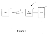
- a remote testing system also referred to herein as the Remote Test Super System (RTSS)
- RTSS Remote Test Super System
- CMU central maintenance unit
- DUT device under test
- the central maintenance unit is also referred to herein as the control system.
- the test equipment 4 is a programmable apparatus that comprises a communications interface 10 for communicating with the CMU 2, a processor 11, memory 12, a plurality of fast analog-to-digital and digital-to-analog convertors 13 and a plurality of sensors 14, to enable the test equipment to output a wide range of test stimuli to the DUT 5 and to receive measurement data from the DUT 5.
- the sensor array may include temperature, current and optical sensors, and the test equipment may also be capable of carrying out complex analysis of RF and other communication signals.
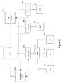
- the test equipment is a vector signal analyser (VSA), a block diagram of which is shown in Figure 3 .
- VSA vector signal analyser
- the VSA includes an arbitrary waveform generator 20, a vector signal generator 21, an analogue signal generator 22, a power monitor and input switch matrix 23 for applying the signals to the DUT 5, a power monitor and output switch matrix 24 for receiving the outputs from the DUT 5, a spectrum analyser 25 and a digitiser 26.
- a VSA is the Agilent 89600.
- test equipment 4 To enable the test equipment 4 to be configured for any particular DUT 5, the test equipment is programmable via test information received from the CMU 2.
- the CMU 2 is a conventional computer programmed to communicate with the test system 4 and other systems, such as test development houses 31, that will be described in detail below. It comprises, for example, a processor 15, memory 16 and a communications interface 17, but it will be understood that it includes all of the components necessary for it to carry out its function, as described in detail below.
- Figures 4 and 5 illustrate a system according to embodiments of the invention that can allow remote testing over a wide area, including globally.
- a CMU 2 is connected to a plurality of test systems 30a - n and to a plurality of distributed test development houses 31a - n.
- Each test development house maintains a real time data warehouse 32a - n which stores information about products that are specific to that test development house.
- a test development house 31a - n may maintain information about all the products for a particular company. The information is maintained in the form of a device model for each product/device.
- the CMU 2 may also maintain information about the test system 30a - n, or this information may be downloaded from the test system itself, in the form of a test system model.
- a test system model By combining the device model for the DUT with the test system model for the test system, an overall system model can be established, which may be associated with particular test information, such as appropriate testing strategies and expected responses to application of those strategies.
- the system model can provide a theoretical output response to a particular stimulus, which takes into account both the way in which that stimulus is generated by the test system, and the response of the device to that stimulus.
- the overall system model may also take into account device models for all of the devices in the installation, and their interconnections.
- the respective test systems 30a - n may be connected to various devices under test DUT.
- all the test systems are the same, but are connected to a wide variety of different types of device under test.
- Figure 5 illustrates that a plurality of DUTs 5a - n can be connected to a single test system 30a via a switch 32. Information regarding which of the DUTs 5a - n is to be tested can be sent to the test system 30a from the CMU. In an alternative configuration, a time division multiplex arrangement is used for testing the various devices, so obviating the need for a switch.
- Figure 5 also illustrates different test development houses 31 a, 31 b being responsible for different sets of DUTs.
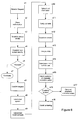
- Figure 6 illustrates a remote testing system process according to the invention.
- the CMU receives a request via a communication link from a user or customer at a remote location, usually where the DUT is located, to carry out a routine equipment inspection/test or to find a fault in the equipment for replacement or repair.
- the CMU establishes the authorisation of the customer (step s2).
- the CMU then establishes the identity of the DUT by information exchange between the CMU, the DUT and a data warehouse for a test development house, as necessary (step s3).
- the identity includes a full data set on the DUT, as well as the environment in which it is currently located together with data for any available logistical support for the DUT.
- the CMU also establishes the identity of the test system in a similar way (step s4).
- the CMU determines whether to proceed (step s5). This could be on any suitable basis, eg. the capability of the system or the level or validity of a particular support contract. If the decision is to proceed, the customer is informed that his request has been confirmed (step s6). If not, the procedure terminates with a suitable message to the customer (step s7).
- the CMU then establishes a remote link to the test system (step s8). Based on the customer's request, for example the device to be tested and the type of test to be performed, the CMU instructs the data warehouse of the test development house to upload test model software for the specific DUT to the test system 30a (step s9).
- the test model software will include information such as the DUT specification, theoretical functional performance, logistical information, lessons learned from previous testing, fault and performance history and up-to-date data, based on the device model held in the data warehouse.
- the CMU then uploads test information to the test system 30a (step s10).
- the test information specifies the tests that are to be performed on the DUT.
- the test information configures the test system into a synthetic instrument that will carry out specified measurements on the DUT.
- the test information includes the measurement and signal generation algorithms that are to be run on the test system and applied to the DUT, as well as the DUT configuration control & simulation provision to be applied to the DUT.
- the test system carries out the tests on the DUT (step s11) based on the software provided by the CMU/data warehouses and downloads the results to the CMU (step s12).
- the CMU accesses information held in relational databases in at least one data warehouse to perform analysis on the test results data in, or nearly in, real time (step s13). For example, where a system model has been established by combining the device model with a test system model, the measured results of applying a particular test can be compared with the theoretical results of applying the test to the system model.
- the CMU determines, from the analysis, if the DUT is fit for continued use, i.e. 'go' or 'no go' (step s14). If the 'no go' condition also provides an indication of the fault found, the customer is informed of proposed corrective action automatically (step s15).
- step s16 If the customer agrees to the proposed corrective action, either at the time or by prior authorisation (step s16), then this is carried out by the CMU or TDH or instructions for manual corrective action are issued by the CMU (step s17).
- testing/diagnosis process may continue (step s18) as described in detail below.
- an expert with appropriate security access is then given access to the services of the real time data warehouse, the TDH and the Internet and/or satellite network from anywhere to anywhere, to include verbal, visual and two-way communications capability.
- the 4th line expert is brought in via web access to overview the test analysis and use the CMU tools of data warehousing to go around the loop again to inform the customer of the proposed corrective action.
- the expert now has the means of interrogating the equipment for information concerning its operation from anywhere to anywhere globally.
- the expert can form a diagnosis about the operation of the equipment.
- the remote service link between the CMU, expert and the customer is then terminated with the mutual agreement of the service provider and the customer.
- the solution is recorded for lessons learned for use on equipment to be tested in the future.
- Embodiments of the invention have so far been described as requiring a separate test system which is used to link to the DUT.
- the test system is connected to a central control/maintenance system via a remote communications link, over which test programs are downloaded to provide a synthetic test capability to the test system.
- various alternative embodiments are possible, as described in the example scenarios in more detail below.
- Remote testing according to the invention is cognitive in that the test can be dynamically adaptive, utilising synthetic measurement, the means for which can be uploaded and downloaded remotely so constantly providing the latest diagnostic techniques.
- This means that the method of testing is not determined by the date of the hardware delivery but can evolve as synthetic measurement techniques evolve.
- the testing can also evolve as the history of the equipment while in service provides both fault-found and general performance history in the operational environment to extend a model of the product. With equipment currently in service for up to 50 years, the use of synthetic measurement, combined with cognitive testing, provides for support of generations of equipment upgrades without having to correspondingly update support equipment.
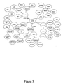
- the cognitive system is illustrated in the invention map as shown in Figure 7
- the interrelationships provided by the invention enable a total end-to-end capability as the means to meet the primary need of "Fault Found” to maximise the continuous use of the DUT.
- This memory map illustrates some of the many associations that make the RTSS application a solution provider.
- This super system structure supports a continuous life cycle process through continuous innovation of applications as well as field support of product DUT'S.
- the super system is an integrated structured mature network architecture which supports innovative products within its structure through the application of interfaces maintained by agreed open standards.
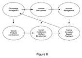
- the invention in this respect balances the need for flexibility to encourage innovation in "Module products development (both Test Systems & DUT)" by emploving "Technology Management” while at the same time minimising the risk to the Super System by retaining a mature Structured Architecture using "Platform Management”.
- the "Platform management” maintains the architecture by defining the standards for "Systems Architecture Interfaces development”.
- the "Service Management” maintains the structure through “Testing, Simulation and Support, providing feedback” for Change management through lessons learned to maintain innovation while at the same time minimising risk.
- the DUT being provided with compatible interfaces with the invention in this super system structured manner makes remote Test more effective providing for greater DUT sustainability over time.
- This is preferably a relational database which may be part of a secure information system and may have the following attributes:
- Information flow associated with measurements taken from the equipment under test is facilitated by the use of data warehousing.
- Data warehousing allows for near real time results and performance analysis handling. Data warehousing therefore operates as a test management system and a repair management system minimising mean time to repair. Data warehousing also operates to optimise the use of equipment/assets, calibration and maintenance cycles through access to optimised product information so maximising mean time between failures.
- the CMU which is likely to be a data warehouse, may provide test storage of the test sequencing. It may contain the following features:
- the CMU may also provide central management of a test data management system. It may contain the following features:
- the CMU may also provide post acquisition analysis and reporting on test data. It may contain the following features: a web interface to allow cross-site access to test analysis data; more generalised production operations performance analysis; product evaluation analysis, and import of locally stored results into main project databases.
- the LAN interface standard may be used for the invention, for interfacing different components.
- a derivative of LAN interfaces is LAN based instruments and standards such as LXI. All major suppliers of test instruments now endorse the LXI standard as they are part of the LXI members consortium.
- LXI is a cost effective modular platform with real time LAN interface enhancements.
- LXI Instruments are web based which is ideal for remote testing purposes. They also have no front panels which can lead to a considerable saving of space and to increased flexibility.
- the system of the invention may consist of a system of three systems: Information - Logistics; Control/Simulation - Interfacing, and Measurement - Validation.
- the Information System provides the informatics; all the information data parameters for test including the equipment logistics, the test system logistics, the equipment performance, calibration, test, configuration, results, analysis, verification and validation parameters.
- the Control and Simulation System provides the control and monitoring or commands and telemetry of the equipment as well as the simulation of the equipment interfacing and aspects of the equipment simulation.
- the Measurement System provides the measurement capability based on international standards to measure the equipment by providing compatible stimulus and monitoring signal generation and analysis.
- VSA Vector Signal Analysis
- Synthetic measurements are preferred as they provide a number of strategic advantages in terms of investment, delivery, capability and capital hardware re use.
- VSA based flexible test system architecture provides the capability for using synthetic measurements with both traditional and new hardware; VSA may be used to undertake measurements not previously possible by conventional means; time saved with the faster measurements has enabled both faster delivery times and the requirement for less test systems investment.
- Provision of Synthetic Measurements can provide a virtual test capability to enable the following:
- the Electronic Calibration unit is now a synthetic calibration standard electrical unit, which emulates a whole range of mechanical Calibration standards by weighted database embedding data techniques to provide a complete standard in one unit which now is better in performance than the individual mechanical standards
- Synthetic Measurement Library SML
- Synthetic measurements based on modulated signals provide for greater flexibility of application using for example communication schemes such as QAM or RADAR signal such as Chirp.
- test times are improved with different types of simultaneous results test domains presented at the same time.
- the configuration shown in Figure 3 provides for the use of simultaneous time, frequency and modulation domain measurements with broadband and broad-spectrum capability. A mix of new synthetic and traditional instruments capability is available..
- This system provides the mix of narrow band with high dynamic range capability traditional harmonics and spurs measurements as well as wide band with good dynamic range capability for modulation measurements.
- the purpose of modelling is to provide a measurement method, which will combine with the equipment to provide a total model of the test system and the equipment.
- design modelling packages will combine with test systems equipment to provide synergy between test designs and equipment designs to improve the overall design verification process. This reduces both timescales and risk with the provision of greater virtual performance detail.
- a virtual product for example provides improved modelling reference design capabilities as well as shorter timescales and increased flexibility as this removes the need for a physical validation product to be built and validated.
- Test design modelling allows virtual product testing, to validate design principles.
- the virtual test measurements can be replaced by real measurements as the real hardware arrives so that an iterative analysis to performance can be made. This reduces analysis time as well as being more robust to changes with greater flexibility. This also has the added benefit of seeing how real element performance affects the overall system before the overall system build is completed.
- This model of the DUT based now on real data can then be used post delivery of the equipment for support, maintenance and fault found activity. The model can then be extended on the basis of lessons learned in the field of operations from the fault/performance history.
- a total system model can therefore be determined from the test system model and the equipment model to provide for operational simulations. This can incorporate uncertainty analysis for various scenarios from which can be determined the full functional tests and the performance tests. From this validation and verification performance analysis reference principles can be derived for qualification of the product as well as maintenance and support of the product. Modelling of the fault/performance history can also predict trends for preventative maintenance and support purposes.
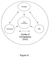
- a competence centre for the system of the invention must have a cost effective functional activity base, to deliver to the customer needs. It must also have the technical capability to meet the customer's product test and maintenance requirements. A centre of competence is required with the critical mass to provide the necessary skills, technology and processes necessary to meet the performance needs.
- a Central Maintenance Unit be the competence centre for support and maintenance purposes.
- the CMU has service information access capabilities as an enabler for a test network. This service will include video, voice and data access to/from the CMU within a, preferably global, network.
- Test support needs to provide information right though from bid to design analysis and product support.
- Test System Design needs to address the application philosophy of design for test of the DUT Product as well as the Test System Products to be used in the application and the analysis tools framework to enable successful verification of the DUT product to be realised.
- Support requirements may also be included in the product design data to provide total cost of ownership.
- Test Development Houses each with their own data warehouse(s) may be responsible, according to the invention, for their own products. These data warehouses may be linked, via standardised interfaces, to the CMU.
- the TDHs may provide the expert knowledge and the equipment "4th line” back up expert assistance when needed.
- the TDHs provide test capabilities information and modelling based on the following:
- the Central Maintenance Unit provides the command and control central hub of the communications network of the system of the invention and the central knowledge base of the test system and the products for 3rd line and 2nd line maintenance expert assistance for field service support activities.
- the CMU has access to the TDHs data warehouses via the real time relational database system and the global network via satellite and the Internet.
- Test data management is based on the Real Time Data Warehouse (RTDW) features with capabilities as follows:
- the satellite network includes: Secure satellite control link
- the satellite global network provides access to a seamless secure communications infrastructure operating services to link the, usually remote, equipment to the CMU.
- This communications network therefore has the ability augmented by the Internet and satellite communications to put an expert anywhere in the world with 4th line information access from the CMU with its knowledge based information systems into contact with the remote equipment. This effectively provides 4th line capabilities at the front line in real time with the latest up to date information.
- Examples of further fields in which the invention could be used are as follows:- space operations, whether Civil or Military to include Satellites, space stations, space platforms, space warehouses and other space vehicles; air theatre operations, whether Civil or Military including aircraft, airships and un-manned Aerial Vehicles; water based Platform operations, whether Civil or Military, and including all water borne craft, submersible vehicles and static rigs whether floating or otherwise; land based field operations, whether Civil or Military, including vehicles, weapons, general electronic equipment, buildings, remote unmanned stations; remote training; reverse access to data processing when a local capability is limited, to provide the necessary data processing power at a remote location; logistical testing at remote weather stations; remote medical applications including synthetic instruments, reconfigurable mobile hospitals and surgeries; remote environmental systems, including irrigation systems; remote Rail network safety test monitoring and maintenance; remote sound monitoring systems to detect fault signatures as a warning maintenance limit with feedback to operators for corrective action in real time as necessary; remote Security systems for monitoring, operation and maintenance; remote building and asset monitoring to include building maintenance and management systems; product service support and tracking, covering
- test coverage and expert access may truly be a remote global coverage anywhere in the world augmented by communications access via the Internet and satellites with field terminals to cover true remote deployment locations in demanding environments.
- experts anywhere in the world may have remote viewing and command capability in real time with remote access anywhere else in the world to provide correlated expert information to assist in the decision making diagnostic process.
- the system may provide a real time remote test capability, a real time data and result processing capability, a real time relational database, search engine and data warehousing for real time data access on DUT products, performance data, library data, logistical data, historical data, test models, DUT models and analysis providing a continuous process operation for diagnostics with the capability of handling large amounts of complex data so making things possible that would not be practical using traditional methods in a workable response timeframe.
- the system may provide for a differential advantage of a new practical timeframe for solutions implementation based on informed decisions providing for new opportunities for solutions provision as a service to give customer advantage.
- the system may be reconfigureable remotely with new personalities of capability augmented by synthetic measurement and calibration upload and downloads to modify the performance and function of the system as synthetic instrumentation to tailor it to the specific requirements of the DUT.
- the system may provide a cognitive capability to adapt to provide diagnostics to enable fault found of DUT'S in remote locations.
- the system may have built in structured data security capability and may include secure communications network functions as a global network provision using Internet and satellite networks to provide access to remote deploved location anywhere globally.
- the system may comprise a super system 'system of systems' structure, with organisational systems management structures, with open standards interfaces provision to address global diagnostic solutions, backed up by scalable networks of data warehouses to meet the needs of any diagnostic challenge.
Landscapes
- Engineering & Computer Science (AREA)
- Computer Networks & Wireless Communication (AREA)
- Signal Processing (AREA)
- Test And Diagnosis Of Digital Computers (AREA)
- Management, Administration, Business Operations System, And Electronic Commerce (AREA)
- Testing Or Calibration Of Command Recording Devices (AREA)
- Testing Electric Properties And Detecting Electric Faults (AREA)
Claims (13)
- Fernprüfsystem (1), umfassend:ein Steuersystem (2), das durch Kommunikationsverbindungen mit einer Vielzahl verteilter relationaler Datenbanken verbunden ist, wobei jede Datenbank einem Testentwicklungshaus zugeordnet ist und Informationen über für dieses Testentwicklungshaus spezifische Produkte speichert, wobei die Informationen wenigstens eines der Folgenden umfassen: Gerätemodelldaten, historische Leistungsdaten und logistische Daten, die für die Produkte spezifisch sind,eine von dem Steuersystem ferne zu prüfende Vorrichtung (5, 5a-n) undein zur Vorrichtung lokales Prüfsystem (4, 30a-n), wobei das Prüfsystem mit der Vorrichtung verbunden werden kann, um Gerätetests durchzuführen, und zur Durchführung von synthetischen Messungen an der zu prüfenden Vorrichtung auf der Basis von Informationen von dem Steuersystem konfiguriert ist,wobei das Steuersystem (2) zur Einrichtung einer Satellitenkommunikationsverbindung (3) mit dem Prüfsystem angeordnet ist,wobei das Steuersystem zum Empfangen von der Vorrichtung zugeordneten Identifizierungsinformationen über einen Informationsaustausch zwischen dem Steuersystem, der zu prüfenden Vorrichtung und wenigstens einer der Datenbanken konfiguriert ist, um auf der Basis der Identifizierungsinformationen einen oder mehrere auf die Vorrichtung anzuwendende(n) Test(s) zu ermitteln, wobei die Identifizierungsinformationen Informationen über die Umgebung, in welcher sie sich aktuell befindet, und Informationen über die logistischen Daten für die zu prüfende Vorrichtung beinhalten; das Steuersystem ferner konfiguriert ist, um Testsoftware für den einen oder die mehreren ermittelten Test(s) an das Prüfsystem zur Ausführung im Prüfsystem und Testinformationen, die den einen oder die mehreren mithilfe der Testsoftware auf die Vorrichtung anzuwendenden Test(s) definieren, zu übertragen, wobei die Testinformationen zum Konfigurieren des Prüfsystems zu einem synthetischen Instrument zur Durchführung spezifizierter Messungen an der zu prüfenden Vorrichtung bereitgestellt werden; das Steuersystem ferner zum Empfangen der Ergebnisse der Tests vom Prüfsystem und für den Zugriff auf Informationen, die in wenigstens einer Datenbank aufbewahrt werden, zur Durchführung einer Analyse der Testergebnisse konfiguriert ist.
- System nach Anspruch 1, wobei die Testsoftware Informationen in Bezug auf die Vorrichtung beinhaltet.
- System nach einem der vorhergehenden Ansprüche, wobei das Steuersystem zum Vergleichen der Ergebnisse mit von einem Systemmodell vorhergesagten Ergebnissen angeordnet ist.
- System nach Anspruch 3, wobei das Systemmodell eine Kombination aus einem Vorrichtungsmodell und einem Prüfsystemmodell umfasst.
- System nach einem der vorhergehenden Ansprüche, wobei das Steuersystem (2) ferner zum Empfangen von Rohdaten von der Vorrichtung (5) als Reaktion auf die angewandten Tests und zur Durchführung von Messungen an den Daten im Steuersystem angeordnet ist.
- Verfahren zum Fernprüfen einer Vorrichtung (5) von einem Steuersystem (2) aus, wobei das Steuersystem durch Kommunikationsverbindungen mit einer Vielzahl verteilter relationaler Datenbanken verbunden ist, wobei jede Datenbank einem Testentwicklungshaus zugeordnet ist und Informationen über für dieses Testentwicklungshaus spezifische Produkte speichert, wobei die Informationen wenigstens eines der Folgenden umfassen: Gerätemodelldaten, historische Leistungsdaten und logistische Daten, die für die Produkte spezifisch sind, wobei das Verfahren Folgendes umfasst:Einrichten einer Satellitenkommunikationsverbindung (3) zwischen dem Steuersystem (2) und einem zur Vorrichtung lokalen Prüfsystem (4, 30a-n), wobei das Prüfsystem zur Durchführung von synthetischen Messungen an der zu prüfenden Vorrichtung auf der Basis von Informationen von dem Steuersystem konfiguriert ist,Empfangen von Identifizierungsinformationen für die Vorrichtung (5) an dem Steuersystem (2) über einen Informationsaustausch zwischen dem Steuersystem, dem Prüfsystem und wenigstens einer der Vielzahl von Datenbanken, wobei die Identifizierungsinformationen Informationen über die Umgebung, in welcher die zu prüfenden Vorrichtung sich aktuell befindet, und Informationen über die logistischen Daten für die zu prüfende Vorrichtung beinhalten,Ermitteln von einem oder mehreren, auf der Basis der Identifizierungsinformationen auf die Vorrichtung (5) anzuwendenden Test(s),Übertragen von Testsoftware für den einen oder die mehreren ermittelten Test(s) an das Prüfsystem zur Ausführung im Prüfsystem,Übertragen von Testinformationen, die den einen oder die mehreren mithilfe der Testsoftware auf die Vorrichtung anzuwendenden Test(s) definieren, an das Prüfsystem (4, 30a-n), wobei die Testinformationen das Prüfsystem zu einem synthetischen Instrument zur Durchführung spezifizierter Messungen an der zu prüfenden Vorrichtung konfigurieren,Ausführen der Testsoftware im Prüfsystem (4, 30an) zum Anwenden des einen oder der mehreren Test(s) auf die Vorrichtung (5),Übertragen der Ergebnisse des einen oder der mehreren Test(s) an das Steuersystem undZugreifen auf Informationen, die in wenigstens einer Datenbank der Vielzahl von Datenbanken aufbewahrt werden, zur Durchführung einer Analyse der Ergebnisse in dem Steuersystem.
- Verfahren nach Anspruch 6, das ferner Folgendes aufweist:Durchsuchen der verteilten Datenlager nach Informationen, die sich auf die Vorrichtung beziehen, undÜbertragen der vorrichtungsbezogenen Informationen an das Prüfsystem (4, 30a-n).
- Verfahren nach Anspruch 7, das ferner Folgendes aufweist:Erhalten von einem oder mehreren Messwerten von der Vorrichtung (5) im Prüfsystem (4, 30a-n) undÜbertragen der Messwerte von dem Prüfsystem (4, 30a-n) zum Steuersystem (2) oderErhalten von Rohdaten von der Vorrichtung (5) im Prüfsystem (4, 30a-n),Übertragen der Messwerte von dem Prüfsystem (4, 30a-n) zum Steuersystem (2) undDurchführen von Messungen an den Daten im Steuersystem (2).
- Verfahren nach Anspruch 8, das Folgendes aufweist:Analysieren der empfangenen Messwerte undÜbertragen einer Diagnose an einen Benutzer des Prüfsystems (4, 30a-n) im Wesentlichen in Echtzeit.
- Verfahren nach Anspruch 9, wobei das Analysieren der empfangenen Messwerte das Vergleichen der Messwerte mit einem Satz erwarteter Messwerte umfasst.
- Verfahren nach Anspruch 10, wobei der Satz erwarteter Messwerte durch Anwenden der Tests auf ein Systemmodell ermittelt werden und das Systemmodell vorzugsweise eine Kombination eines Modells der zu prüfenden Vorrichtung mit einem Modell des Prüfsystems umfasst.
- Computerprogramm, das bei Ausführung durch einen Prozessor zur Durchführung eines Verfahrens nach einem der Ansprüche 7 bis 11 konfiguriert ist.
- Fernprüfsystem (1) nach Anspruch 1, das Folgendes aufweist:eine Vielzahl von vom Steuersystem (2) entfernten zu prüfenden Vorrichtungen (5, 5a-n) undjeweilige zu den Vorrichtungen lokale Prüfsysteme (30a-n), wobei die Prüfsysteme mit den Vorrichtungen verbunden werden können, um Gerätetests durchzuführen, und das Steuersystem zur Einrichtung einer Kommunikationsverbindung (3) mit jedem der Prüfsysteme angeordnet ist,wobei das Steuersystem für jede Vorrichtung zum Empfangen von Ergebnissen der auf die Vorrichtung angewendeten Tests, zum Analysieren der Ergebnisse der Tests und zum Empfehlen weiterer Maßnahmen, im Wesentlichen in Echtzeit, und vorzugsweise zum Suchen nach Informationen in Bezug auf eine Vorrichtung in einer Vielzahl von verteilten Datenbanken als Reaktion auf das Empfangen der Identifizierungsinformationen für die Vorrichtung angeordnet ist.
Priority Applications (1)
| Application Number | Priority Date | Filing Date | Title |
|---|---|---|---|
| EP08750805.7A EP2153581B1 (de) | 2007-06-05 | 2008-06-05 | Fernprüfsystem und verfahren |
Applications Claiming Priority (4)
| Application Number | Priority Date | Filing Date | Title |
|---|---|---|---|
| GB0710720A GB0710720D0 (en) | 2007-06-05 | 2007-06-05 | Remote support and testing of equipment |
| EP07270030A EP2001159A1 (de) | 2007-06-05 | 2007-06-05 | Fernunterstützung und überprüfung einer Anlage |
| EP08750805.7A EP2153581B1 (de) | 2007-06-05 | 2008-06-05 | Fernprüfsystem und verfahren |
| PCT/GB2008/050410 WO2008149153A1 (en) | 2007-06-05 | 2008-06-05 | Remote testing system and method |
Publications (2)
| Publication Number | Publication Date |
|---|---|
| EP2153581A1 EP2153581A1 (de) | 2010-02-17 |
| EP2153581B1 true EP2153581B1 (de) | 2013-07-31 |
Family
ID=39590426
Family Applications (1)
| Application Number | Title | Priority Date | Filing Date |
|---|---|---|---|
| EP08750805.7A Active EP2153581B1 (de) | 2007-06-05 | 2008-06-05 | Fernprüfsystem und verfahren |
Country Status (6)
| Country | Link |
|---|---|
| US (1) | US8145966B2 (de) |
| EP (1) | EP2153581B1 (de) |
| JP (1) | JP5390513B2 (de) |
| CN (1) | CN101766001B (de) |
| CA (1) | CA2688471C (de) |
| WO (1) | WO2008149153A1 (de) |
Cited By (1)
| Publication number | Priority date | Publication date | Assignee | Title |
|---|---|---|---|---|
| US11293969B2 (en) | 2019-03-12 | 2022-04-05 | Rohde & Schwarz Gmbh & Co. Kg | System and method for automatic test-setup hardware detection and extension |
Families Citing this family (73)
| Publication number | Priority date | Publication date | Assignee | Title |
|---|---|---|---|---|
| FR2891380B1 (fr) * | 2005-09-23 | 2007-11-30 | Thales Sa | Procede et systeme de validation des defaillances pour aerodynes |
| CA2666199C (en) | 2006-03-27 | 2015-08-25 | Nielsen Media Research, Inc. | Methods and systems to meter media content presented on a wireless communication device |
| ES2670420T3 (es) * | 2006-07-07 | 2018-05-30 | F. Hoffmann-La Roche Ag | Dispositivo de administración de fluidos y métodos de funcionamiento del mismo |
| WO2008149153A1 (en) * | 2007-06-05 | 2008-12-11 | Astrium Limited | Remote testing system and method |
| US8140289B2 (en) * | 2007-10-25 | 2012-03-20 | Raytheon Company | Network-centric processing |
| US8503991B2 (en) * | 2008-04-03 | 2013-08-06 | The Nielsen Company (Us), Llc | Methods and apparatus to monitor mobile devices |
| US8204498B1 (en) * | 2008-09-30 | 2012-06-19 | Sprint Communications Company L.P. | Automated content download tool |
| US8453119B2 (en) * | 2009-10-14 | 2013-05-28 | GM Global Technology Operations LLC | Online formal verification of executable models |
| US20110235873A1 (en) * | 2010-03-24 | 2011-09-29 | Bio-Rad Laboratories (Israel) Inc. | Extracting device-related data from graphical user interface |
| CN102209098B (zh) * | 2010-03-30 | 2015-06-03 | 北京华虹集成电路设计有限责任公司 | 智能卡远程检测方法及系统 |
| FR2958911B1 (fr) * | 2010-04-19 | 2012-04-27 | Snecma | Procede et systeme de surveillance du niveau d'huile contenue dans un reservoir d'un moteur d'aeronef |
| CN102572910B (zh) * | 2010-12-22 | 2016-03-16 | 鼎桥通信技术有限公司 | 终端话务量测试方法及系统 |
| WO2012122243A1 (en) * | 2011-03-08 | 2012-09-13 | Google Inc. | Remote testing |
| US20130069675A1 (en) * | 2011-03-25 | 2013-03-21 | Dorlen Products, Inc. | Conductive fluid leak detector |
| CN102185734A (zh) * | 2011-04-18 | 2011-09-14 | 华为软件技术有限公司 | 接口自动化测试方法及服务器 |
| US8924073B2 (en) * | 2011-06-20 | 2014-12-30 | Bae Systems Information And Electronic Systems Integration Inc. | Portable maintenance aid based preload test unit and stray voltage detector |
| CN102494806A (zh) * | 2011-12-21 | 2012-06-13 | 中国计量学院 | 数显式温度指示仪表远程自动检定系统 |
| US20130269537A1 (en) | 2012-04-16 | 2013-10-17 | Eugenio Minvielle | Conditioning system for nutritional substances |
| US20130269538A1 (en) | 2012-04-16 | 2013-10-17 | Eugenio Minvielle | Transformation system for nutritional substances |
| US9541536B2 (en) | 2012-04-16 | 2017-01-10 | Eugenio Minvielle | Preservation system for nutritional substances |
| US10219531B2 (en) | 2012-04-16 | 2019-03-05 | Iceberg Luxembourg S.A.R.L. | Preservation system for nutritional substances |
| US9016193B2 (en) * | 2012-04-16 | 2015-04-28 | Eugenio Minvielle | Logistic transport system for nutritional substances |
| US8733631B2 (en) | 2012-04-16 | 2014-05-27 | Eugenio Minvielle | Local storage and conditioning systems for nutritional substances |
| US9414623B2 (en) | 2012-04-16 | 2016-08-16 | Eugenio Minvielle | Transformation and dynamic identification system for nutritional substances |
| US9436170B2 (en) | 2012-04-16 | 2016-09-06 | Eugenio Minvielle | Appliances with weight sensors for nutritional substances |
| US9564064B2 (en) | 2012-04-16 | 2017-02-07 | Eugenio Minvielle | Conditioner with weight sensors for nutritional substances |
| US9528972B2 (en) | 2012-04-16 | 2016-12-27 | Eugenio Minvielle | Dynamic recipe control |
| US9072317B2 (en) | 2012-04-16 | 2015-07-07 | Eugenio Minvielle | Transformation system for nutritional substances |
| US9080997B2 (en) | 2012-04-16 | 2015-07-14 | Eugenio Minvielle | Local storage and conditioning systems for nutritional substances |
| US8851365B2 (en) | 2012-04-16 | 2014-10-07 | Eugenio Minvielle | Adaptive storage and conditioning systems for nutritional substances |
| US9429920B2 (en) | 2012-04-16 | 2016-08-30 | Eugenio Minvielle | Instructions for conditioning nutritional substances |
| US9460633B2 (en) | 2012-04-16 | 2016-10-04 | Eugenio Minvielle | Conditioner with sensors for nutritional substances |
| US9171061B2 (en) | 2012-04-16 | 2015-10-27 | Eugenio Minvielle | Local storage and conditioning systems for nutritional substances |
| US9069340B2 (en) | 2012-04-16 | 2015-06-30 | Eugenio Minvielle | Multi-conditioner control for conditioning nutritional substances |
| CN103425119B (zh) * | 2012-05-23 | 2018-10-19 | 株式会社堀场制作所 | 测试系统、设备管理装置和车辆性能测试系统 |
| CN102854455A (zh) * | 2012-09-21 | 2013-01-02 | 成都市中州半导体科技有限公司 | 集成电路测试系统及集成电路测试系统的控制方法 |
| US9830247B2 (en) | 2012-09-27 | 2017-11-28 | Nxp Usa, Inc. | Digital device and method |
| CN103034231B (zh) * | 2012-12-04 | 2015-08-05 | 中国电力科学研究院 | 一种用于工控设备的测试床方法 |
| CN103049668B (zh) * | 2012-12-28 | 2015-09-30 | 中国电子科技集团公司第三十六研究所 | 星载电子系统在轨可靠性的预测系统及方法 |
| US20140215269A1 (en) * | 2013-01-28 | 2014-07-31 | Hewlett-Packard Development Company, L.P. | Test infrastructure simulation |
| CN103207606B (zh) * | 2013-03-27 | 2015-07-22 | 西北工业大学 | 嵌入式多源制造信息感知装置及方法 |
| CN103309724B (zh) * | 2013-05-16 | 2017-05-10 | 中国电子科技集团公司第四十一研究所 | 一种基于自动测试系统软件适配器的虚拟通道通用管理方法 |
| US9379855B2 (en) * | 2013-06-03 | 2016-06-28 | MiCOM Labs, Inc. | Method and apparatus for a remote modular test system |
| KR101522307B1 (ko) * | 2013-08-14 | 2015-05-21 | 어니컴 주식회사 | 앱테스트시스템 및 앱테스트방법 |
| US9836371B2 (en) | 2013-09-20 | 2017-12-05 | Oracle International Corporation | User-directed logging and auto-correction |
| US10790062B2 (en) | 2013-10-08 | 2020-09-29 | Eugenio Minvielle | System for tracking and optimizing health indices |
| EP2882141A1 (de) * | 2013-12-04 | 2015-06-10 | Exfo Inc. | Netzprüfungssystem |
| JO3466B1 (ar) | 2013-12-20 | 2020-07-05 | Takeda Pharmaceuticals Co | مواد ضابطة لتترا هيدرو بيريدوبيرازينات من gpr6 |
| USD762081S1 (en) | 2014-07-29 | 2016-07-26 | Eugenio Minvielle | Device for food preservation and preparation |
| US9558093B2 (en) * | 2014-07-30 | 2017-01-31 | Microsoft Technology Licensing, Llc | Visual tools for failure analysis in distributed systems |
| CN104243585B (zh) * | 2014-09-18 | 2017-08-11 | 中国航空无线电电子研究所 | 基于分布式健康诊断的信道模拟与综合验证系统及其方法 |
| WO2016093836A1 (en) * | 2014-12-11 | 2016-06-16 | Hewlett Packard Enterprise Development Lp | Interactive detection of system anomalies |
| CN104469166B (zh) * | 2014-12-26 | 2018-09-18 | 国网重庆市电力公司电力科学研究院 | 一种图像采集控制装置和方法 |
| US9686027B2 (en) | 2015-05-20 | 2017-06-20 | Viasat, Inc. | Validation of a two-way satellite communication system without utilizing a satellite |
| US11021274B1 (en) * | 2015-06-22 | 2021-06-01 | Triad National Security, Llc | Cubesat system |
| US10803074B2 (en) | 2015-08-10 | 2020-10-13 | Hewlett Packard Entperprise Development LP | Evaluating system behaviour |
| US9749064B2 (en) * | 2015-08-28 | 2017-08-29 | FedEx Supply Chain Logistics & Electronics, Inc. | Automated radio frequency testing management system |
| CN106909131B (zh) * | 2015-12-22 | 2020-10-16 | 上海西门子线路保护系统有限公司 | 实验仪器的管理系统 |
| CN105676843B (zh) * | 2016-04-13 | 2018-09-25 | 中国汽车技术研究中心 | 一种新能源汽车对标分析与评价系统及其方法 |
| CN107305515A (zh) * | 2016-04-25 | 2017-10-31 | Emc公司 | 计算机实现方法、计算机程序产品以及计算系统 |
| US10782348B2 (en) * | 2017-03-10 | 2020-09-22 | Keithley Instruments, Llc | Automatic device detection and connection verification |
| US10389458B2 (en) * | 2017-03-24 | 2019-08-20 | The Boeing Company | Method and apparatus for testing RF performance of a satellite wiring harness and signal processing units |
| CN107390551A (zh) * | 2017-07-20 | 2017-11-24 | 郑州云海信息技术有限公司 | 对测试机进行远程控制的系统及方法 |
| CN108039923B (zh) * | 2017-12-25 | 2021-06-08 | 摩比天线技术(深圳)有限公司 | 多频段n阶交调测试方法和系统 |
| CN108898243A (zh) * | 2018-06-04 | 2018-11-27 | 宁德师范学院 | 一种电力系统输电网络安全性测试系统 |
| CN109063507A (zh) * | 2018-07-13 | 2018-12-21 | 上海派兰数据科技有限公司 | 一种用于医院信息系统分析的通用设计模型 |
| JP6884743B2 (ja) * | 2018-11-27 | 2021-06-09 | アンリツ株式会社 | 測定装置、測定システム及び測定方法 |
| US10841019B1 (en) * | 2019-09-12 | 2020-11-17 | National Instruments Corporation | Cross-correlation measurements for modulation quality measurements |
| US11796621B2 (en) | 2019-09-12 | 2023-10-24 | National Instruments Corporation | Fast convergence method for cross-correlation based modulation quality measurements |
| CN112905428B (zh) * | 2019-12-04 | 2024-08-20 | 菜鸟智能物流控股有限公司 | 测试方法、装置、电子设备和存储介质 |
| CN111948572A (zh) * | 2020-08-20 | 2020-11-17 | 珠海云洲智能科技有限公司 | 一种无人船的自动检测电路及自动检测装置 |
| CN112910538B (zh) * | 2021-01-05 | 2022-04-19 | 航天科工空间工程发展有限公司 | 一种模型驱动的低轨通信卫星载荷测试方法和系统 |
| CN117234909B (zh) * | 2023-09-08 | 2024-06-11 | 浪潮智慧科技有限公司 | 一种基于计算机系统的水利应用软件测试系统 |
Citations (2)
| Publication number | Priority date | Publication date | Assignee | Title |
|---|---|---|---|---|
| EP1229449A1 (de) * | 2001-01-31 | 2002-08-07 | Sony International (Europe) GmbH | Geräteferndiagnose |
| WO2004029808A2 (en) * | 2002-09-30 | 2004-04-08 | Sony Ericsson Mobile Communications Ab | System and method for remote servicing of embedded devices |
Family Cites Families (40)
| Publication number | Priority date | Publication date | Assignee | Title |
|---|---|---|---|---|
| US3882305A (en) | 1974-01-15 | 1975-05-06 | Kearney & Trecker Corp | Diagnostic communication system for computer controlled machine tools |
| US4766595A (en) | 1986-11-26 | 1988-08-23 | Allied-Signal Inc. | Fault diagnostic system incorporating behavior models |
| JP3238936B2 (ja) * | 1992-01-29 | 2001-12-17 | 株式会社日立製作所 | プラント運転管理方法および装置 |
| US5724504A (en) | 1995-06-01 | 1998-03-03 | International Business Machines Corporation | Method for measuring architectural test coverage for design verification and building conformal test |
| US6279131B1 (en) * | 1995-08-30 | 2001-08-21 | Lucent Technologies Inc. | Automated testing system with minimized dependency on specific test instruments |
| US5794254A (en) * | 1996-12-03 | 1998-08-11 | Fairbanks Systems Group | Incremental computer file backup using a two-step comparison of first two characters in the block and a signature with pre-stored character and signature sets |
| US5978578A (en) | 1997-01-30 | 1999-11-02 | Azarya; Arnon | Openbus system for control automation networks |
| US5950147A (en) | 1997-06-05 | 1999-09-07 | Caterpillar Inc. | Method and apparatus for predicting a fault condition |
| JP3366837B2 (ja) | 1997-08-15 | 2003-01-14 | 株式会社小松製作所 | 機械の異常監視装置および方法 |
| US6405145B1 (en) | 1998-03-20 | 2002-06-11 | National Instruments Corporation | Instrumentation system and method which performs instrument interchangeability checking |
| US6295492B1 (en) | 1999-01-27 | 2001-09-25 | Infomove.Com, Inc. | System for transmitting and displaying multiple, motor vehicle information |
| JP2001058269A (ja) * | 1999-08-20 | 2001-03-06 | Toshiba Plant Kensetsu Co Ltd | 自動溶接機の検査装置および検査方法 |
| US7020595B1 (en) | 1999-11-26 | 2006-03-28 | General Electric Company | Methods and apparatus for model based diagnostics |
| JP2002005699A (ja) * | 2000-06-21 | 2002-01-09 | Mitsubishi Heavy Ind Ltd | リモート検査支援方法及びリモート検査支援システム |
| US6745011B1 (en) | 2000-09-01 | 2004-06-01 | Telephia, Inc. | System and method for measuring wireless device and network usage and performance metrics |
| US6754844B1 (en) * | 2000-10-31 | 2004-06-22 | Intel Corporation | Diagnostic configuration management of embedded network devices |
| US20040236843A1 (en) * | 2001-11-15 | 2004-11-25 | Robert Wing | Online diagnosing of computer hardware and software |
| DE10152765B4 (de) | 2001-07-13 | 2015-11-12 | Siemens Aktiengesellschaft | Verfahren zur elektronischen Bereitstellung von Diensten für Maschinen über eine Datenkommunikationsverbindung |
| US7302675B2 (en) | 2001-08-14 | 2007-11-27 | National Instruments Corporation | System and method for analyzing a graphical program using debugging graphical programs |
| US7113883B1 (en) * | 2001-08-24 | 2006-09-26 | Vi Technology, Inc. | Test configuration and data management system and associated method for enterprise test operations |
| US7275235B2 (en) | 2001-08-29 | 2007-09-25 | Molinari Alfred A | Graphical application development system for test, measurement and process control applications |
| US6756907B2 (en) | 2002-06-11 | 2004-06-29 | Jerrell Penn Hollaway | Maintainance support system for an electrical apparatus |
| US7155639B2 (en) * | 2002-08-22 | 2006-12-26 | Sun Microsystems, Inc. | Compliance testing communication protocols implemented on resource-constrained computing devices |
| EP1420316B1 (de) | 2002-11-18 | 2012-05-23 | Rockwell Automation Technologies, Inc. | Sofortige Nachrichtenübermittlung (Instant Messaging) zur Ereignismitteilung und zum Datenaustausch in einer industriellen Steuerungsumgebung |
| EP1510922A1 (de) * | 2003-08-04 | 2005-03-02 | Sony International (Europe) GmbH | Verfahren und System zur Ferndiagnose von Geräten |
| EP1505505A1 (de) * | 2003-08-08 | 2005-02-09 | Sony International (Europe) GmbH | Verfahren und System zur Ferndiagnose von Geräten |
| US7200529B2 (en) | 2003-08-15 | 2007-04-03 | National Instruments Corporation | Automatic configuration of function blocks in a signal analysis system |
| US20060031476A1 (en) | 2004-08-05 | 2006-02-09 | Mathes Marvin L | Apparatus and method for remotely monitoring a computer network |
| US20060101135A1 (en) * | 2004-10-25 | 2006-05-11 | Jiang Li | Network modeling systems and methods |
| US20060129892A1 (en) * | 2004-11-30 | 2006-06-15 | Microsoft Corporation | Scenario based stress testing |
| US7617063B2 (en) * | 2005-01-18 | 2009-11-10 | Paul Tiegs | Remote witness testing system |
| US9288078B2 (en) * | 2005-03-25 | 2016-03-15 | Qualcomm Incorporated | Apparatus and methods for managing content exchange on a wireless device |
| US8719419B2 (en) * | 2005-04-21 | 2014-05-06 | Qualcomm Incorporated | Methods and apparatus for determining aspects of multimedia performance of a wireless device |
| US20070005323A1 (en) | 2005-06-30 | 2007-01-04 | Patzer Aaron T | System and method of automating the addition of programmable breakpoint hardware to design models |
| US7970594B2 (en) | 2005-06-30 | 2011-06-28 | The Mathworks, Inc. | System and method for using model analysis to generate directed test vectors |
| US7844439B2 (en) | 2006-03-10 | 2010-11-30 | Edsa Micro Corporation | Systems and methods for real-time protective device evaluation in an electrical power distribution system |
| US7449876B2 (en) | 2006-05-03 | 2008-11-11 | Agilent Technologies, Inc. | Swept-frequency measurements with improved speed using synthetic instruments |
| US8155639B2 (en) * | 2007-03-26 | 2012-04-10 | At&T Mobility Ii Llc | System and method for computer noteboook electromagnetic compatibility analysis |
| WO2008149153A1 (en) * | 2007-06-05 | 2008-12-11 | Astrium Limited | Remote testing system and method |
| US20090124250A1 (en) * | 2007-11-14 | 2009-05-14 | Topaltzas Dimitrios M | System and Method for Testing Mobile Telephone Devices using a Plurality of Communication Protocols |
-
2008
- 2008-06-05 WO PCT/GB2008/050410 patent/WO2008149153A1/en active Application Filing
- 2008-06-05 CA CA2688471A patent/CA2688471C/en active Active
- 2008-06-05 JP JP2010510889A patent/JP5390513B2/ja not_active Expired - Fee Related
- 2008-06-05 US US12/602,941 patent/US8145966B2/en not_active Expired - Fee Related
- 2008-06-05 CN CN2008801006597A patent/CN101766001B/zh not_active Expired - Fee Related
- 2008-06-05 EP EP08750805.7A patent/EP2153581B1/de active Active
Patent Citations (2)
| Publication number | Priority date | Publication date | Assignee | Title |
|---|---|---|---|---|
| EP1229449A1 (de) * | 2001-01-31 | 2002-08-07 | Sony International (Europe) GmbH | Geräteferndiagnose |
| WO2004029808A2 (en) * | 2002-09-30 | 2004-04-08 | Sony Ericsson Mobile Communications Ab | System and method for remote servicing of embedded devices |
Cited By (1)
| Publication number | Priority date | Publication date | Assignee | Title |
|---|---|---|---|---|
| US11293969B2 (en) | 2019-03-12 | 2022-04-05 | Rohde & Schwarz Gmbh & Co. Kg | System and method for automatic test-setup hardware detection and extension |
Also Published As
| Publication number | Publication date |
|---|---|
| CA2688471C (en) | 2017-01-17 |
| US20100218044A1 (en) | 2010-08-26 |
| JP2010530062A (ja) | 2010-09-02 |
| EP2153581A1 (de) | 2010-02-17 |
| CN101766001B (zh) | 2012-11-28 |
| CA2688471A1 (en) | 2008-12-11 |
| CN101766001A (zh) | 2010-06-30 |
| JP5390513B2 (ja) | 2014-01-15 |
| US8145966B2 (en) | 2012-03-27 |
| WO2008149153A1 (en) | 2008-12-11 |
Similar Documents
| Publication | Publication Date | Title |
|---|---|---|
| EP2153581B1 (de) | Fernprüfsystem und verfahren | |
| CN108431705B (zh) | 使用i/o抽象的现场设备配置的过程工厂中的配置 | |
| JP2010530062A5 (de) | ||
| CN108631854A (zh) | 用于测试卫星线束与信号处理单元的rf性能的方法与装置 | |
| EP2001159A1 (de) | Fernunterstützung und überprüfung einer Anlage | |
| CN104569934A (zh) | 一种雷达故障处理系统 | |
| RU2604362C1 (ru) | Информационно-управляющий комплекс автоматизированной системы управления подготовкой двигательных установок и технологическим оборудованием ракет космического назначения на техническом и стартовом комплексах | |
| US20160005242A1 (en) | Predictive Automated Maintenance System (PAMS) | |
| KR20180118474A (ko) | 다품종 생산을 위한 유연 조립 시스템 및 생산 라인 재구성 방법 | |
| Calà et al. | Migration towards digital manufacturing automation—an assessment approach | |
| CN102566443A (zh) | 基于addl的综合化航电系统模型仿真验证系统及方法 | |
| CN109491910A (zh) | 一种保护逻辑和控制逻辑的可视化仿真调试方法及系统 | |
| CN104597862A (zh) | 用于空间操控任务联试演练的天地回路联试系统及方法 | |
| CN108802511A (zh) | 一种电池管理单元的测试方法及系统 | |
| Zhilkina et al. | Strategy of introduction of information system in trade and logistics company | |
| Kanstrén et al. | Architectures and experiences in testing IoT communications | |
| CN106772460A (zh) | 一种北斗用户终端测试系统 | |
| Sorensen et al. | Development of a comprehensive mission operations system designed to operate multiple small satellites | |
| CN209330129U (zh) | 一种分布式动态射频测试接口装置 | |
| Keller et al. | Health management engineering environment and open integration platform | |
| Frank et al. | Transitioning autonomous systems technology research to a flight software environment | |
| CN104717028A (zh) | 一种基于硬件在环的无线链路验证系统及方法 | |
| Arreghini et al. | An Approach to T&E of Military SDR Platforms and Waveforms: the LANCERS Lab | |
| CN108134832B (zh) | 基于网络的多路仪表端口的透明映射方法 | |
| CN109992457A (zh) | 层次化可配置式微小卫星的测试系统 |
Legal Events
| Date | Code | Title | Description |
|---|---|---|---|
| PUAI | Public reference made under article 153(3) epc to a published international application that has entered the european phase |
Free format text: ORIGINAL CODE: 0009012 |
|
| 17P | Request for examination filed |
Effective date: 20091125 |
|
| AK | Designated contracting states |
Kind code of ref document: A1 Designated state(s): AT BE BG CH CY CZ DE DK EE ES FI FR GB GR HR HU IE IS IT LI LT LU LV MC MT NL NO PL PT RO SE SI SK TR |
|
| AX | Request for extension of the european patent |
Extension state: AL BA MK RS |
|
| 17Q | First examination report despatched |
Effective date: 20100802 |
|
| DAX | Request for extension of the european patent (deleted) | ||
| GRAP | Despatch of communication of intention to grant a patent |
Free format text: ORIGINAL CODE: EPIDOSNIGR1 |
|
| GRAS | Grant fee paid |
Free format text: ORIGINAL CODE: EPIDOSNIGR3 |
|
| GRAA | (expected) grant |
Free format text: ORIGINAL CODE: 0009210 |
|
| AK | Designated contracting states |
Kind code of ref document: B1 Designated state(s): AT BE BG CH CY CZ DE DK EE ES FI FR GB GR HR HU IE IS IT LI LT LU LV MC MT NL NO PL PT RO SE SI SK TR |
|
| REG | Reference to a national code |
Ref country code: GB Ref legal event code: FG4D Ref country code: CH Ref legal event code: EP |
|
| REG | Reference to a national code |
Ref country code: AT Ref legal event code: REF Ref document number: 625185 Country of ref document: AT Kind code of ref document: T Effective date: 20130815 |
|
| REG | Reference to a national code |
Ref country code: IE Ref legal event code: FG4D |
|
| REG | Reference to a national code |
Ref country code: DE Ref legal event code: R096 Ref document number: 602008026423 Country of ref document: DE Effective date: 20130926 |
|
| REG | Reference to a national code |
Ref country code: NL Ref legal event code: T3 |
|
| REG | Reference to a national code |
Ref country code: AT Ref legal event code: MK05 Ref document number: 625185 Country of ref document: AT Kind code of ref document: T Effective date: 20130731 |
|
| REG | Reference to a national code |
Ref country code: LT Ref legal event code: MG4D |
|
| PG25 | Lapsed in a contracting state [announced via postgrant information from national office to epo] |
Ref country code: PT Free format text: LAPSE BECAUSE OF FAILURE TO SUBMIT A TRANSLATION OF THE DESCRIPTION OR TO PAY THE FEE WITHIN THE PRESCRIBED TIME-LIMIT Effective date: 20131202 Ref country code: CY Free format text: LAPSE BECAUSE OF FAILURE TO SUBMIT A TRANSLATION OF THE DESCRIPTION OR TO PAY THE FEE WITHIN THE PRESCRIBED TIME-LIMIT Effective date: 20130821 Ref country code: BE Free format text: LAPSE BECAUSE OF FAILURE TO SUBMIT A TRANSLATION OF THE DESCRIPTION OR TO PAY THE FEE WITHIN THE PRESCRIBED TIME-LIMIT Effective date: 20130731 Ref country code: HR Free format text: LAPSE BECAUSE OF FAILURE TO SUBMIT A TRANSLATION OF THE DESCRIPTION OR TO PAY THE FEE WITHIN THE PRESCRIBED TIME-LIMIT Effective date: 20130731 Ref country code: SE Free format text: LAPSE BECAUSE OF FAILURE TO SUBMIT A TRANSLATION OF THE DESCRIPTION OR TO PAY THE FEE WITHIN THE PRESCRIBED TIME-LIMIT Effective date: 20130731 Ref country code: IS Free format text: LAPSE BECAUSE OF FAILURE TO SUBMIT A TRANSLATION OF THE DESCRIPTION OR TO PAY THE FEE WITHIN THE PRESCRIBED TIME-LIMIT Effective date: 20131130 Ref country code: NO Free format text: LAPSE BECAUSE OF FAILURE TO SUBMIT A TRANSLATION OF THE DESCRIPTION OR TO PAY THE FEE WITHIN THE PRESCRIBED TIME-LIMIT Effective date: 20131031 Ref country code: LT Free format text: LAPSE BECAUSE OF FAILURE TO SUBMIT A TRANSLATION OF THE DESCRIPTION OR TO PAY THE FEE WITHIN THE PRESCRIBED TIME-LIMIT Effective date: 20130731 Ref country code: AT Free format text: LAPSE BECAUSE OF FAILURE TO SUBMIT A TRANSLATION OF THE DESCRIPTION OR TO PAY THE FEE WITHIN THE PRESCRIBED TIME-LIMIT Effective date: 20130731 |
|
| PG25 | Lapsed in a contracting state [announced via postgrant information from national office to epo] |
Ref country code: LV Free format text: LAPSE BECAUSE OF FAILURE TO SUBMIT A TRANSLATION OF THE DESCRIPTION OR TO PAY THE FEE WITHIN THE PRESCRIBED TIME-LIMIT Effective date: 20130731 Ref country code: PL Free format text: LAPSE BECAUSE OF FAILURE TO SUBMIT A TRANSLATION OF THE DESCRIPTION OR TO PAY THE FEE WITHIN THE PRESCRIBED TIME-LIMIT Effective date: 20130731 Ref country code: SI Free format text: LAPSE BECAUSE OF FAILURE TO SUBMIT A TRANSLATION OF THE DESCRIPTION OR TO PAY THE FEE WITHIN THE PRESCRIBED TIME-LIMIT Effective date: 20130731 Ref country code: ES Free format text: LAPSE BECAUSE OF FAILURE TO SUBMIT A TRANSLATION OF THE DESCRIPTION OR TO PAY THE FEE WITHIN THE PRESCRIBED TIME-LIMIT Effective date: 20130731 Ref country code: FI Free format text: LAPSE BECAUSE OF FAILURE TO SUBMIT A TRANSLATION OF THE DESCRIPTION OR TO PAY THE FEE WITHIN THE PRESCRIBED TIME-LIMIT Effective date: 20130731 Ref country code: GR Free format text: LAPSE BECAUSE OF FAILURE TO SUBMIT A TRANSLATION OF THE DESCRIPTION OR TO PAY THE FEE WITHIN THE PRESCRIBED TIME-LIMIT Effective date: 20131101 |
|
| PG25 | Lapsed in a contracting state [announced via postgrant information from national office to epo] |
Ref country code: CY Free format text: LAPSE BECAUSE OF FAILURE TO SUBMIT A TRANSLATION OF THE DESCRIPTION OR TO PAY THE FEE WITHIN THE PRESCRIBED TIME-LIMIT Effective date: 20130731 |
|
| PG25 | Lapsed in a contracting state [announced via postgrant information from national office to epo] |
Ref country code: EE Free format text: LAPSE BECAUSE OF FAILURE TO SUBMIT A TRANSLATION OF THE DESCRIPTION OR TO PAY THE FEE WITHIN THE PRESCRIBED TIME-LIMIT Effective date: 20130731 Ref country code: RO Free format text: LAPSE BECAUSE OF FAILURE TO SUBMIT A TRANSLATION OF THE DESCRIPTION OR TO PAY THE FEE WITHIN THE PRESCRIBED TIME-LIMIT Effective date: 20130731 Ref country code: DK Free format text: LAPSE BECAUSE OF FAILURE TO SUBMIT A TRANSLATION OF THE DESCRIPTION OR TO PAY THE FEE WITHIN THE PRESCRIBED TIME-LIMIT Effective date: 20130731 Ref country code: SK Free format text: LAPSE BECAUSE OF FAILURE TO SUBMIT A TRANSLATION OF THE DESCRIPTION OR TO PAY THE FEE WITHIN THE PRESCRIBED TIME-LIMIT Effective date: 20130731 Ref country code: CZ Free format text: LAPSE BECAUSE OF FAILURE TO SUBMIT A TRANSLATION OF THE DESCRIPTION OR TO PAY THE FEE WITHIN THE PRESCRIBED TIME-LIMIT Effective date: 20130731 |
|
| PLBE | No opposition filed within time limit |
Free format text: ORIGINAL CODE: 0009261 |
|
| STAA | Information on the status of an ep patent application or granted ep patent |
Free format text: STATUS: NO OPPOSITION FILED WITHIN TIME LIMIT |
|
| 26N | No opposition filed |
Effective date: 20140502 |
|
| REG | Reference to a national code |
Ref country code: DE Ref legal event code: R097 Ref document number: 602008026423 Country of ref document: DE Effective date: 20140502 |
|
| PG25 | Lapsed in a contracting state [announced via postgrant information from national office to epo] |
Ref country code: MC Free format text: LAPSE BECAUSE OF FAILURE TO SUBMIT A TRANSLATION OF THE DESCRIPTION OR TO PAY THE FEE WITHIN THE PRESCRIBED TIME-LIMIT Effective date: 20130731 |
|
| REG | Reference to a national code |
Ref country code: CH Ref legal event code: PL |
|
| REG | Reference to a national code |
Ref country code: IE Ref legal event code: MM4A |
|
| PG25 | Lapsed in a contracting state [announced via postgrant information from national office to epo] |
Ref country code: CH Free format text: LAPSE BECAUSE OF NON-PAYMENT OF DUE FEES Effective date: 20140630 Ref country code: LI Free format text: LAPSE BECAUSE OF NON-PAYMENT OF DUE FEES Effective date: 20140630 Ref country code: IE Free format text: LAPSE BECAUSE OF NON-PAYMENT OF DUE FEES Effective date: 20140605 |
|
| PG25 | Lapsed in a contracting state [announced via postgrant information from national office to epo] |
Ref country code: MT Free format text: LAPSE BECAUSE OF FAILURE TO SUBMIT A TRANSLATION OF THE DESCRIPTION OR TO PAY THE FEE WITHIN THE PRESCRIBED TIME-LIMIT Effective date: 20130731 |
|
| PG25 | Lapsed in a contracting state [announced via postgrant information from national office to epo] |
Ref country code: BG Free format text: LAPSE BECAUSE OF FAILURE TO SUBMIT A TRANSLATION OF THE DESCRIPTION OR TO PAY THE FEE WITHIN THE PRESCRIBED TIME-LIMIT Effective date: 20130731 |
|
| REG | Reference to a national code |
Ref country code: FR Ref legal event code: PLFP Year of fee payment: 9 |
|
| PG25 | Lapsed in a contracting state [announced via postgrant information from national office to epo] |
Ref country code: HU Free format text: LAPSE BECAUSE OF FAILURE TO SUBMIT A TRANSLATION OF THE DESCRIPTION OR TO PAY THE FEE WITHIN THE PRESCRIBED TIME-LIMIT; INVALID AB INITIO Effective date: 20080605 Ref country code: TR Free format text: LAPSE BECAUSE OF FAILURE TO SUBMIT A TRANSLATION OF THE DESCRIPTION OR TO PAY THE FEE WITHIN THE PRESCRIBED TIME-LIMIT Effective date: 20130731 |
|
| REG | Reference to a national code |
Ref country code: FR Ref legal event code: PLFP Year of fee payment: 10 |
|
| REG | Reference to a national code |
Ref country code: FR Ref legal event code: PLFP Year of fee payment: 11 |
|
| PGFP | Annual fee paid to national office [announced via postgrant information from national office to epo] |
Ref country code: LU Payment date: 20200618 Year of fee payment: 13 |
|
| PGFP | Annual fee paid to national office [announced via postgrant information from national office to epo] |
Ref country code: NL Payment date: 20200625 Year of fee payment: 13 Ref country code: IT Payment date: 20200623 Year of fee payment: 13 |
|
| REG | Reference to a national code |
Ref country code: DE Ref legal event code: R079 Ref document number: 602008026423 Country of ref document: DE Free format text: PREVIOUS MAIN CLASS: H04L0012240000 Ipc: H04L0041000000 |
|
| REG | Reference to a national code |
Ref country code: NL Ref legal event code: MM Effective date: 20210701 |
|
| PG25 | Lapsed in a contracting state [announced via postgrant information from national office to epo] |
Ref country code: LU Free format text: LAPSE BECAUSE OF NON-PAYMENT OF DUE FEES Effective date: 20210605 |
|
| PG25 | Lapsed in a contracting state [announced via postgrant information from national office to epo] |
Ref country code: NL Free format text: LAPSE BECAUSE OF NON-PAYMENT OF DUE FEES Effective date: 20210701 |
|
| PG25 | Lapsed in a contracting state [announced via postgrant information from national office to epo] |
Ref country code: IT Free format text: LAPSE BECAUSE OF NON-PAYMENT OF DUE FEES Effective date: 20210605 |
|
| PGFP | Annual fee paid to national office [announced via postgrant information from national office to epo] |
Ref country code: GB Payment date: 20240620 Year of fee payment: 17 |
|
| PGFP | Annual fee paid to national office [announced via postgrant information from national office to epo] |
Ref country code: DE Payment date: 20240619 Year of fee payment: 17 |
|
| PGFP | Annual fee paid to national office [announced via postgrant information from national office to epo] |
Ref country code: FR Payment date: 20240628 Year of fee payment: 17 |