EP2153172B1 - Correspondance cartographique pour applications de sécurité - Google Patents
Correspondance cartographique pour applications de sécurité Download PDFInfo
- Publication number
- EP2153172B1 EP2153172B1 EP08759551.8A EP08759551A EP2153172B1 EP 2153172 B1 EP2153172 B1 EP 2153172B1 EP 08759551 A EP08759551 A EP 08759551A EP 2153172 B1 EP2153172 B1 EP 2153172B1
- Authority
- EP
- European Patent Office
- Prior art keywords
- processing unit
- sub
- cartography
- elements
- map
- Prior art date
- Legal status (The legal status is an assumption and is not a legal conclusion. Google has not performed a legal analysis and makes no representation as to the accuracy of the status listed.)
- Active
Links
- 238000000034 method Methods 0.000 claims description 52
- 238000004422 calculation algorithm Methods 0.000 claims description 17
- 238000011156 evaluation Methods 0.000 claims description 12
- 238000005259 measurement Methods 0.000 claims description 7
- 238000005303 weighing Methods 0.000 claims description 4
- 238000004364 calculation method Methods 0.000 description 61
- 238000013507 mapping Methods 0.000 description 9
- 230000007717 exclusion Effects 0.000 description 8
- 239000013598 vector Substances 0.000 description 8
- 230000006870 function Effects 0.000 description 5
- 238000006243 chemical reaction Methods 0.000 description 4
- 230000008569 process Effects 0.000 description 4
- 238000012937 correction Methods 0.000 description 3
- 230000033001 locomotion Effects 0.000 description 3
- 230000001133 acceleration Effects 0.000 description 2
- 230000008901 benefit Effects 0.000 description 2
- 230000008859 change Effects 0.000 description 2
- 238000004891 communication Methods 0.000 description 2
- 238000011161 development Methods 0.000 description 2
- 230000018109 developmental process Effects 0.000 description 2
- 230000006978 adaptation Effects 0.000 description 1
- 238000004458 analytical method Methods 0.000 description 1
- 238000013459 approach Methods 0.000 description 1
- 239000013256 coordination polymer Substances 0.000 description 1
- 230000001419 dependent effect Effects 0.000 description 1
- 238000005315 distribution function Methods 0.000 description 1
- 230000008030 elimination Effects 0.000 description 1
- 238000003379 elimination reaction Methods 0.000 description 1
- LIWAQLJGPBVORC-UHFFFAOYSA-N ethylmethylamine Chemical compound CCNC LIWAQLJGPBVORC-UHFFFAOYSA-N 0.000 description 1
- 238000001914 filtration Methods 0.000 description 1
- 230000006872 improvement Effects 0.000 description 1
- 238000012067 mathematical method Methods 0.000 description 1
- 230000003446 memory effect Effects 0.000 description 1
- 238000012805 post-processing Methods 0.000 description 1
- 230000009467 reduction Effects 0.000 description 1
- 238000006467 substitution reaction Methods 0.000 description 1
- 230000002123 temporal effect Effects 0.000 description 1
- 238000012795 verification Methods 0.000 description 1
Images


Classifications
-
- G—PHYSICS
- G01—MEASURING; TESTING
- G01C—MEASURING DISTANCES, LEVELS OR BEARINGS; SURVEYING; NAVIGATION; GYROSCOPIC INSTRUMENTS; PHOTOGRAMMETRY OR VIDEOGRAMMETRY
- G01C21/00—Navigation; Navigational instruments not provided for in groups G01C1/00 - G01C19/00
- G01C21/26—Navigation; Navigational instruments not provided for in groups G01C1/00 - G01C19/00 specially adapted for navigation in a road network
- G01C21/28—Navigation; Navigational instruments not provided for in groups G01C1/00 - G01C19/00 specially adapted for navigation in a road network with correlation of data from several navigational instruments
- G01C21/30—Map- or contour-matching
-
- B—PERFORMING OPERATIONS; TRANSPORTING
- B60—VEHICLES IN GENERAL
- B60T—VEHICLE BRAKE CONTROL SYSTEMS OR PARTS THEREOF; BRAKE CONTROL SYSTEMS OR PARTS THEREOF, IN GENERAL; ARRANGEMENT OF BRAKING ELEMENTS ON VEHICLES IN GENERAL; PORTABLE DEVICES FOR PREVENTING UNWANTED MOVEMENT OF VEHICLES; VEHICLE MODIFICATIONS TO FACILITATE COOLING OF BRAKES
- B60T2210/00—Detection or estimation of road or environment conditions; Detection or estimation of road shapes
- B60T2210/30—Environment conditions or position therewithin
- B60T2210/36—Global Positioning System [GPS]
-
- B—PERFORMING OPERATIONS; TRANSPORTING
- B60—VEHICLES IN GENERAL
- B60T—VEHICLE BRAKE CONTROL SYSTEMS OR PARTS THEREOF; BRAKE CONTROL SYSTEMS OR PARTS THEREOF, IN GENERAL; ARRANGEMENT OF BRAKING ELEMENTS ON VEHICLES IN GENERAL; PORTABLE DEVICES FOR PREVENTING UNWANTED MOVEMENT OF VEHICLES; VEHICLE MODIFICATIONS TO FACILITATE COOLING OF BRAKES
- B60T2250/00—Monitoring, detecting, estimating vehicle conditions
- B60T2250/06—Sensor zero-point adjustment; Offset compensation
Definitions
- the invention relates to the calculation of position data of an object.
- the invention relates to a device for matching a measured position of an object with information of a digital map, a system, the use of a device, a vehicle, a method, a program element and a computer-readable medium.
- Safety-related vehicle assistance systems must be able to predict dangerous situations that may result in vehicle control loss or collision. If such a situation is predicted in good time, then this may u.U. be avoided, autonomously e.g. by decelerating the vehicle, or warning the driver of this imminent situation by means of a warning system.
- the current position must be known.
- This current position can be detected by a variety of means, such as a GPS receiver, which can be a low-cost, global solution.
- the GPS or other positioning system has an error that does not always make it possible to specify a position exactly in a road.
- a map can always have some accuracy errors and deviations from the actual cartography, making it difficult to determine the position directly in a road or even impossible.
- the US2006 / 0047423 A1 a navigation system and a method for detecting a deviation of a vehicle from a predetermined by the navigation system route.
- a device which comprises a GPS sensor and a dead reckoning sensor.
- the GPS sensor first determines position and time information from GPS signals while the inertial sensor determines a relative position based on previously determined position information.
- a filter module a current position of the vehicle is determined from the information of the GPS sensor and the dead reckoning sensor.
- the positional data determined by the filter is used by a map matching unit to match with a digital map and to generate a match probability between the current position and the map matching determined position.
- the coincidence probability is then transmitted to a unit for detecting a deviation and to a unit for following the route.
- the EP 0 522 862 A1 describes a GPS navigation system with selective position offset correction.
- the navigation system is designed for use in a mobile object and comprises a GPS positioning device for receiving GPS signals and outputting first position data as well as an automatic positioning device for determining the current position and for outputting second position data. Furthermore, the navigation system comprises a determination device for comparing the first and second position data and for determining a difference between the first and second position data and a correction device for adding an offset value to the first position data if the difference between the first and second position data is greater than or equal to is a predetermined value.
- the automatic positioning device comprises according to EP 0 522 862 A1 one Locating sensor, a speed sensor and a position calculation unit for outputting position data based on these sensors.
- the position calculation unit includes a microcomputer for reading map data of a CD-ROM drive based on the first and second position data and for adapting the position data to the map data using a map matching unit.
- From the DE 44 32 208 A1 is a navigation method using a vectorized terrain map known. Based on an originating location of a vehicle and values provided by a odometer, compass and GPS navigation system, the location of the vehicle is calculated and transmitted to a vectorized electronic map to select a path segment that is the most likely location of the vehicle contains.
- the site is calculated using a Kalman filter that creates significant uncertainty area data surrounding the new calculated location.
- the significant data generated by the Kalman filter is applied as an input to vectorized map comparison means, which now determine the location of within the uncertainty area path sections that may potentially contain the real location of the vehicle.
- a device for matching a measured position of an object with information of a digital map, a system, a use of a device, a vehicle, a method, a program element, and a computer-readable medium are given according to the features of the independent claims. Further developments of the invention will become apparent from the dependent claims. The described embodiments equally relate to the device, the system, the use, the vehicle, the method, the program element and the computer-readable medium.
- a device for matching a measured position of an object (for example a vehicle) with information of a digital map is specified, the device having a Computing unit has.
- the arithmetic unit is designed for a first selection of cartographic elements of the card on the basis of the measured position and on the basis of a predefined error.
- the arithmetic unit is designed to provide the selected cartographic elements to a first and a second subunit.
- the first selection can additionally or substitution also be carried out on the basis of coordinates of the cartographic elements by the arithmetic unit.
- a node is a point in space that has GPS coordinates such as latitude and longitude.
- a segment is a line connecting two nodes, and a path is a set of grouped segments.
- this embodiment of the invention provides a fast exclusion filter that selects those cartographic elements with their given position that satisfy a predefined error criterion.
- this criterion can be given mathematically by a maximum distance, which is represented graphically by a circle with a radius of the maximum distance around the measured position. For example, it is possible to calculate whether the segments are within the maximum error according to different formulas.
- This filter method for fast exclusion of cartography elements is also used, for example, in Fig. 1 and Fig. 4 clarified.
- map matching can be done faster and with less computational power.
- the aim of a subsequent map matching method is to decide based on the position of a GPS, for example, which has a specific error, between possible points of a map, to which point the position determination refers. In certain cases, for example, after receiving a GPS position, it must be decided in which road the GPS receiver is located. First of all, it has to be analyzed, why a comparison or a map matching and especially with which method or with which map matching procedure has to be done. Then the best method is extracted and the arithmetic units are then evaluated.
- the measured position which can not be exact due to various sources of error, can be matched with map data.
- the map data can also be faulty. Therefore, for example, the two nearest roads may be selected from a map with many roads, but more distant. In this case, roads are to be regarded as a segment or cartographic element.
- a subsequent calculation of the probability on the basis of the vehicle condition, in which of the two roads the vehicle is actually located, can be calculated and compared in parallel by means of various methods.
- the device and the arithmetic unit can work with mathematical methods or algorithms which can be executed, for example, on a CPU.
- a reduction and elimination of unnecessary cartographic elements or segments from the digital map takes place, as a result of which, for example, a simplified adjustment can then take place.
- the arithmetic unit can furthermore be designed in such a way that it makes the selected cartographic elements available to any number of further sub-computation units.
- the use of only one Unterrechentician is of course also possible.
- the predefined error may be an error value based on an error distribution of a GPS system.
- the error distribution of a GPS system corresponds to a normal distribution, from which a predefined error can be derived.
- This error value can also be adapted and optimized iteratively after individual adjustments.
- the device eliminates the number of data to the cartographic elements such that subsequent improvement or verification of the measured position focuses only on a small map and only has to calculate and evaluate the relevant segments with their positions.
- the information of the card is pre-filtered for complex post-processing. This can mean a significant saving in time and computing power.
- the value of the predefined error is adapted adaptively to the situation. That is, the device increases the maximum error circle if no map matching can be performed at all within the covered area. If the map matching is possible, the system reduces the maximum error circle up to the theoretically predefined value.
- the selection of the relevant cartographic elements by the device can be used to subsequently carry out a simultaneous weighing and evaluation of the various cartographic elements by different modules or by different sub-calculation units. It could this Sub-units are considered as independent map-matching algorithms that can operate simultaneously, in parallel, and independently of each other. Without the first selection by the device, matching a measured position of an object with digital map information would be far more complex and difficult to perform in real time.
- the measured position may also be a non-current data record and also an at least partial calculation of the measured position from an older position data record is possible.
- a navigation capability is thus not an essential part of this embodiment.
- the new position can be fed again as feedback information to the device and / or the arithmetic unit. This corresponds to a feedback loop for optimized map matching.
- a position determination unit such as a GPS unit can be used in the object.
- GPS is representative of all global navigation satellite systems (GNSS), such as GPS, Galileo, GLONASS (Russia), COMPASS (China), IRNSS (India), ...
- GNSS global navigation satellite systems
- digital maps is also understood to mean maps for advanced driver assistance systems (ADAS) without navigation.
- ADAS advanced driver assistance systems
- the digital map format used can be selected according to criteria and parameters and possibly changed in order to enable this and any other embodiment of the invention.
- An adaptation of the format to the algorithms used is possible.
- a format can be used or generated to improve the selection of cartographic elements according to the invention and the parallel calculation of values of individual sub-calculation units.
- the sub-calculation units can also be physically contained in the arithmetic unit.
- the apparatus further comprises the first and the second sub-calculation unit, wherein the first sub-calculation unit is designed to calculate a first value for each selected mapping element by means of a first method or a first method. Furthermore, the second sub-calculation unit is designed to calculate a second value for each selected cartography element by means of a second method or a second method, wherein the first and the second values are calculated in the same unit of measure or are converted to the same unit of measure.
- the sub-calculation units and the methods used are designed in such a way that a conversion of respectively specific physical units of the sub-calculation unit to a predefined basic unit, the same unit of measure, takes place.
- algorithms are used to calculate the values, a selection of the algorithms is necessary in such a way that always the predefined unit of measurement is used for each used sub-calculation unit.
- the choice of the same unit of measurement can be specified by the device, by the arithmetic unit, that is to say the rapid exclusion filter, or also by a user.
- the calculation of the values in the various sub-calculation units in a common unit enables the subsequent direct comparison of values of the individual cartographic elements. This allows a combination of different calculation methods and thus provides more information for deciding on a comparison. This minimizes a possible mismatch error.
- the map matching algorithm thus applies different analysis methods to the selected cartographic elements and then evaluates the results of all methods. In order to be able to compare the values of the different methods, the normally different units have to be converted or transformed.
- a distance module which may be regarded as a first inter-unit, indicates a distance
- an angle module which can be regarded as a second processor, indicates an angle. Since angles are not comparable with distances, the device according to the invention indicates a possibility of defining units of measurement and of providing a conversion for the individual units of the individual sub-calculation units.
- the apparatus is further adapted to add the first and second values of each selected cartographic element to a respective final value.
- the cartographic elements collect certain scores from the individual sub-units or modules.
- the probabilities of the cartographic elements correspond to the scores, to show the actual position of the object.
- an order based on these probabilities of the cartographic elements is created. This sequence is used for matching or map matching.
- the device is further configured to evaluate the first sub-calculation unit and an evaluation of the second sub-calculation unit, resulting in a corresponding weighting of the two values of each selected mapping element.
- the evaluation of the sub-calculation units can be controlled and carried out by the arithmetic unit, but also an evaluation by the user of the device or an automatic evaluation on the basis of provided measurement data is possible.
- All sub-calculation units or modules can be regarded as independent map-matching algorithms. By evaluating or modifying a tuning parameter, it is possible to use only one module for map matching and to execute it anyway. For this purpose, for example, the influences of the other sub-calculation units can be set to zero via the tuning parameters or the weighting. So this device is capable of a map matching as a combination of different To provide sub-calculation units or various map matching algorithms. If there is a specific card situation, the combination of the sub-calculation units can be made with appropriate evaluation, in which the decision-making method is optimal.
- the apparatus is further adapted to a second selection of a target mapping element from the selected mapping elements based on the end values. Furthermore, the device is designed such that the adjustment takes place on the basis of the target cartography element.
- the target cartography element is the one cartographic element that is the most likely due to the created order and possibly the evaluation.
- the measured position of the object can be replaced by the position of the target cartographic element.
- the position of the target cartography element is the new adjusted position of the object.
- the target cartography element is that cartographic element which has first fulfilled the conditions of an error criterion in a selection and has the highest probability in a second calculating algorithm step.
- the device has a first filter, wherein the first filter is designed to determine a state of the object.
- the first filter which may also be referred to as a module, estimates the system state when an object is traveling, for example by applying a Kalman filter to the measured position of the object.
- a Kalman filter In the case of a vehicle, it is assumed that the object performs movements according to Newtonian principles. In order to fully assess the system state, therefore, the linear distance covered, the speed and the acceleration must be evaluated.
- the filter can take all previous values to predict the next value. However, this is done recursively by self-correcting an internal model that should describe the reality.
- the filter considers a multidimensional system in which the temporal development of a process can be described.
- the device further comprises a second filter, wherein the second filter is designed to detect a fault of the measured position.
- This filter which, like the first filter, can for example be preceded in time by the selection of cartographic elements, evaluates the deviation of the measured position with the help of the errors committed during map matching.
- This module can evaluate, for example, the GPS deviation using a Kalman filter.
- the process state of the Kalman filter corresponds to the deviation in length and width. With the well-known equations of the Kalman filter For each GPS position estimate, a new GPS deviation rating for latitude and longitude is obtained.
- At least one of the filters has the properties of a Kalman filter.
- a system for matching a measured position of an object with information of a digital map for a vehicle comprising a device according to one of the previous embodiments and a satellite navigation receiver.
- This system can be used, for example, in vehicles for more accurate and predictive positioning or position correction determination. This can provide significant benefits for setting down an automatic emergency call (ECall) as well as an automated technical service call (BCall), but also for advanced driver assistance systems (ADAS).
- ECall automatic emergency call
- BCall automated technical service call
- ADAS advanced driver assistance systems
- a device according to one of the preceding embodiments is indicated in a vehicle.
- a vehicle is provided with a device according to one of the previous embodiments.
- the vehicle is, for example, a motor vehicle, such as a car, bus or truck or even a rail vehicle, a ship, an aircraft, as well as a helicopter or airplane or, for example, a bicycle.
- a motor vehicle such as a car, bus or truck or even a rail vehicle, a ship, an aircraft, as well as a helicopter or airplane or, for example, a bicycle.
- ADAS Advanced Driver Assistance System
- a method for matching a measured position of an object with information of a digital map comprising the following steps: providing a computing unit, performing a selection of map elements of the map based on the measured position and on basis a predefined error by the arithmetic unit and the provision of the selected cartographic elements to one and a second sub-unit by the arithmetic unit.
- a medium is indicated, wherein the medium provides the program element for download.
- the program element is furthermore suitable, if it is executed on a processor, which instructs the processor to carry out the steps specified above.
- an existing program item to be put into a state by means of a download that, when executed on a processor, instructs the processor to perform the above-mentioned steps.
- a computer-readable medium having stored on the computer-readable medium a program element which, when executed on a processor, directs the processor to perform the above-identified steps.
- a basic consideration of the invention is that the device performs a quick pre-selection of cartographic elements of the digital map, then performs a parallel calculation of the selected cartographic elements by various methods, these methods providing all the same units of measure. A subsequent evaluation of the results then leads to an optimal map matching decision. This can save significant time and computing power.
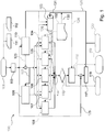
- Fig. 1 shows a device 100 for matching a measured position 101 of an object with information of a digital map 102.
- the information of the map can be given for example by cartography elements and corresponding data.
- a computing unit 103 which can also be designed as a fast-exclusion filter, is provided.
- the digital map 102 the information stored in it, such as the information about positions of different cartography elements, the arithmetic unit 103 is available. This is illustrated by the arrows 130, 131.
- this information may be provided directly to the sub-units 104, 105, 106, 107 and 108, which is exemplified by the arrow 126.
- the computing unit 103 executes one of several possible algorithms, which selects the appropriate cartographic elements based on the measured position 101 and on the basis of a predefined error. After this selection becomes the reduced record the sub-units 104, 105, 106, 107 and 108 are provided.
- the first sub-calculation unit 104 calculates a first value for each selected mapping element by a first method
- the second sub-calculation unit 105 calculates a second value for each selected mapping element by a second method.
- a first filter 109 and a second filter 110 are shown.
- the first filter 109 is set up for determining the system state of the object and, for example in the case of a vehicle, can statistically estimate the position, the speed and the acceleration of the vehicle. An execution of this filter as a Kalman filter is possible. To determine this condition the filter 109 is provided with the GPS position in corrected version 122. After the system state has been determined by the filter 109, the result can be made available to one or more sub-calculation units. In the embodiment shown here, the sub-calculation unit 107 and the sub-calculation unit 104 are supplied with the information about the current system state.
- the second filter 110 which may for example also be designed as a Kalman filter, serves to iteratively eliminate or minimize errors in the GPS position by, for example, an estimation method.
- the filter 110 can thus be supplied with the current measured position of the object 101 after a possible check by means of a check sum 113. But also a feedback of the error value after a successful adjustment by means of feedback loop 121 to the second filter 110 is possible.
- the current measured position 110 is provided by a satellite navigation receiver 111. It can For example, NMEA files are used for communication between navigation devices 112.
- Both filters 109 and 110 can determine the system state or the position error by means of a stochastic state estimation, but it is also possible to provide sensor data, for example of a vehicle to the two filters, or a combination of the use of sensor data and the stochastic estimation. A combination of the two methods can be used to minimize errors based on faulty sensor data.
- each of the selected cartographic elements has been assigned a value per method unit by the methods of the individual slave units 104 to 108, these values of each cartographic element are added to a respective final value 114. These final values correspond to the probability that the object will be at the position of the respective cartographic element located. Then, an order of the cartographic elements may be created according to their likelihood to decide which actual position to use for matching. This corresponds to the target cartography element with its geographical position 115.
- the device 100 is the FIG. 1 in order to output the target cartography element, the new adjusted position and the error of the new adjusted position compared to the originally measured position 118, 119 and 120.
- an error value 117 is obtained by means of the new adjusted position and the provision of the measured position 125 calculated.
- This error may further be provided feedback to the offset eliminating filter 110 in a feedback loop 121 in order to iteratively calculate a position of the object which is as precisely as possible adjusted with renewed steps.
- the first sub-calculation unit 104 may, for example, carry out the method of the road distance module.
- the second sub-calculation unit 105 can, for example, calculate values of the cartographic elements by means of the method of a memory module.
- the third sub-calculation unit 106 can, for example, estimate the relevant cartography elements with regard to their probability by means of the method of the probability of passing or by means of a size module.
- the fourth sub-calculation unit 107 may, for example, execute the method of an angle module.
- the fifth subunit 108 can, for example, carry out the method of a distance module.
- the distance module calculates a score for each cartographic element.
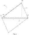
- ⁇ cs corresponds to the angle between the link vector and the individual segment vectors
- v the estimated actual speed
- ⁇ t the estimated time increment between the last sample and the next one.
- speed v and time increment ⁇ t must be estimated. This can be realized, for example, with the aid of a Kalman filter. Graphically, these average induced errors in FIG. 3 shown. The average of a linear sequence starting at zero is half the maximum value. The maximum error is sin ⁇ cs. • Base and base are equal to v • ⁇ t .
- the memory module considers that, logically, the last known road or at least one associated road is more likely to be the current road.
- the memory module can be adapted very much to your own needs, and it is possible to change the memory effect of this module by setting parameters accordingly.
- a higher score in a segment corresponds to a higher probability for that segment to be the right one.
- the point system is inverted compared to the points system of the other modules because it can be adjusted by the user and thus corresponds to the description of a probability distribution function. For this reason, the result (the score) of this module corresponds to this - inverted - function.
- the memory indicates that a segment has been previously selected or that it has been directly connected to a segment.
- the path probability / size module ensures that a larger road is rated with a higher probability, firstly because it drives more vehicles and secondly it has a larger surface area.
- the amount of vehicles in a road and therefore the number depends corresponding segments from a number of factors that are difficult to determine. It is assumed that this amount of vehicle is proportional to the size of the road. In this way, it is assumed that the vehicles are evenly distributed on the road.
- This score is converted by the memory module before being compared to the other scores because the other scores are low if they are likely to be segments and high if they are unlikely segments.
- S d is the estimate of the distance traveled on the road, for example calculated with the state of a Kalman filter.
- the Road Distance Module or Road Distance Module is a completely new method of map matching.
- a Kalman filter is used to estimate the current state of motion and the distance covered in the road.
- This module corresponds to a completely independent map matching, which does not require the further sub-calculation units and methods. This task only requires a starting point and a special decision module for cases of doubt. Combining this module with the other modules, this need is already covered by all other modules.
- This module estimates longitudinally and determines the position by longitudinal projection of the distance covered in the current road. This means that the distance traveled is determined and all possible positions in the road corresponding to this distance are searched for. Starting from these positions, it follows all possible road directions and indicates the distance to it.
- This module can also make a decision without GPS information if during this time without connection no other roads intersect, which is normally the case in tunnels. Therefore, this module offers the system the possibility of "dead reckoning" (also called Dead Reckoning). This is another significant advantage of the invention.
- this module weighs two possible positions.
- the two drawn vehicles represent the two possible positions and d n +11 is the estimate of the next distance traveled.
- This module is computationally complex because the minimum distance to each possible street point has to be calculated backwards, because from one point A to another point B different paths can exist and all have to be analyzed.
- the calculation of the estimated traveled distance is now carried out, for example, with a Kalman filter.
- map matching is used on motor vehicles, the accuracy of this module can increase significantly because the vehicle sensors can be used to estimate this distance traveled and not the derived information from the GPS, as in the Kalman filter. Another Kalman filter using vehicle sensors should then be implemented to calculate these traveled distances.
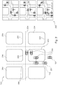
- FIG. 12 shows a digital map 102 showing a measured position of a vehicle 101 that may not match the infrastructure of the map shown.
- the vehicle 200 is situated within a building 203 according to measured positions.
- the device and the method according to the invention can determine the actual position of the vehicle by means of the quick-exclusion filter function and by the combination of various methods for calculating and evaluating the various cartographic elements. The exact determination can also be made iteratively and with a control loop.
- exemplary cartography elements 204, roads and buildings are shown.
- Fig. 2 the new adjusted position 201 after the target mapping element 115 has been selected. This corresponds to the new adjusted position of the vehicle 201. Further shows Fig. 2 a possible calculation of the new adjusted position 202 by means of vectorial representation of segments and distances of the vehicle.
- Fig. 3 shows the induced error in case the sub-unit executes the method of an angle module.
- the value v ⁇ T 305 can be represented as shown.
- An angle between the road vector and the segment vector 300 is indicated.
- the induced error 303 during the next time interval is shown on the right edge of the image as the height of the triangle.
- Fig. 4 shows a graphical representation of the function of the rapid exclusion filter or the arithmetic unit
- the arithmetic unit is designed to a first selection of cartography elements of the map based on the measured position and based on a predefined error.
- the algorithm 400 is shown for fast exclusion of segments of a card.
- a square area 402 with the boundaries 401 is shown.
- the maximum error Dmax 403 which is shown as the radius of a circle, describes the area around the measured position 101, in which the permissible segments may lie.
- segments that have been sorted out correctly 404, as well as segments that have not been sorted out, although they do not satisfy the ideal filter condition of the maximum distance Dmax 405, are shown. Correctly unsorted segments 406 are also shown.
- cartographic element means both nodes, segments, paths and closed paths.
- Fig. 4 2 shows a graphical representation of the mode of operation of an exemplary embodiment of the arithmetic unit or of the fast-exclusion filter with regard to the first selection.
- This is an exemplary algorithm of the arithmetic unit.
- This quick-exclusion filter is needed to balance all modules or sub-calculation units at the same time. It is a relatively complex process to select the segments within a maximum radius. The permissible area of this selection is ideally a circle.
- the computational complexity is even higher when the cartographic elements are segments because the shortest distance to the line formed by the two ends of the segment must be calculated by projecting the center onto that line and then evaluating it, if this projection is inside the segment. If this is not the case, the minimum distance corresponds to the distance to the nearest segment end.
- Another valid approach is to turn the shape of the maximum distance, which is ideally a circle, into a square. This makes a linear comparison of the distances possible.
- a second filter can be used for the filtered elements. This means that only the filtered elements (elements within the square) are filtered again with a holistic filter (only the elements in the circle are selected). With a square area it is possible to set four different boundaries: H + , H - , V + and V - .
- This exemplary filter method for fast exclusion of cartography elements is in FIG. 4 graphically illustrated.
- Fig. 5 shows an equivalent parallelogram 500 for calculation by the distance module. This calculation, for example, in the sub-calculation units 104 to 108 of the Fig. 1 be executed. It is the height 501, the base 502, the angle 503, P1 504, P2 505 and C designated 506.
- Fig. 6 is a schematic representation of a digital map 102 in which the calculation is represented by a road distance module 600.
- Fig. 7 is a schematic representation of a flowchart illustrating a method according to an embodiment of the invention.
- a computing unit is provided.
- step S2 a selection of cartographic elements of the map based on the measured position and on the basis of a predefined error by the arithmetic unit is executed.
- step S3 represents a provision of the selected cartographic elements to a first and a second sub-calculation unit by the arithmetic unit.
Claims (14)
- Dispositif (100) destiné à aligner une position mesurée (101) d'un objet avec l'information d'une carte numérique (102), le dispositif présentant :une unité de calcul (103) ;une première (104) et une deuxième (105) sous-unité de calcul ;l'unité de calcul étant réalisée pour une première sélection d'éléments de cartographie (404, 405, 406) de la carte sur la base de la position mesurée et sur la base d'une erreur (403) prédéfinie ;l'unité de calcul étant également réalisée pour la fourniture des éléments de cartographie sélectionnés à la première (104) et à la deuxième (105) sous-unité de calcul,caractérisé en ce que
la première et la deuxième sous-unité de calcul sont agencées de telle sorte qu'elles réalisent un examen et une analyse simultanés des éléments de cartographie au moyen d'algorithmes de map-matching fonctionnant de façon simultanée, parallèle et indépendamment les uns des autres. - Dispositif selon la revendication 1,
la première sous-unité de calcul étant réalisée pour le calcul d'une première valeur pour chaque élément de cartographie sélectionné au moyen d'une première méthode ;
la deuxième sous-unité de calcul étant réalisée pour le calcul d'une deuxième valeur pour chaque élément de cartographie sélectionné au moyen d'une deuxième méthode ; et
les premières et les deuxièmes valeurs étant calculées dans la même unité de mesure. - Dispositif selon la revendication 2,
le dispositif étant réalisé également pour l'addition de la première et de la deuxième valeur de chaque élément de cartographie sélectionné pour donner une valeur finale respective. - Dispositif selon l'une des revendications précédentes,
le dispositif étant réalisé également pour une évaluation de la première sous-unité de calcul et pour une évaluation de la deuxième sous-unité de calcul, ce qui conduit à une pondération correspondante des deux valeurs de chaque élément de cartographie sélectionné. - Dispositif selon l'une des revendications 3 ou 4,
le dispositif étant réalisé également pour une deuxième sélection d'un élément de cartographie cible (115) à partir des éléments de cartographie sélectionnés sur la base des valeurs finales ; et
le dispositif étant également réalisé de telle sorte que l'alignement s'effectue sur la base de l'élément de cartographie cible. - Dispositif selon l'une des revendications précédentes, le dispositif présentant également :un premier filtre (109) ;le premier filtre étant réalisé pour la détermination d'un état de l'objet.
- Dispositif selon l'une des revendications précédentes, le dispositif présentant également :un deuxième filtre (110) ;le deuxième filtre étant réalisé pour la détermination d'une erreur de la position mesurée de l'objet.
- Dispositif selon l'une des revendications 6 ou 7,
au moins un des filtres étant réalisé en tant que filtre de Kalman. - Système destiné à aligner une position mesurée d'un objet avec l'information d'une carte numérique pour un véhicule, le système présentant :un récepteur de navigation par satellite (11), le système étant caractérisé par :un dispositif selon l'une des revendications précédentes.
- Utilisation d'un dispositif selon l'une des revendications 1 à 8 dans un véhicule (200).
- Véhicule (200) avec un dispositif selon l'une des revendications 1 à 8.
- Procédé destiné à aligner une position mesurée d'un objet avec l'information d'une carte numérique, le procédé présentant les étapes suivantes :fourniture d'une unité de calcul (S1) ;sélection d'éléments de cartographie de la carte sur la base de la position mesurée et sur la base d'une erreur prédéfinie par l'unité de calcul (S2) ;fourniture des éléments de cartographie sélectionnés à une première et une deuxième sous-unité de calcul par l'unité de calcul (S3),caractérisé en ce que
la première et la deuxième sous-unité de calcul réalisent un examen et une analyse simultanés des éléments de cartographie au moyen d'algorithmes de map-matching fonctionnant de façon simultanée, parallèle et indépendamment les uns des autres. - Elément de programme qui, quand il est exécuté sur un processeur, pilote le processeur pour qu'il effectue les étapes suivantes :fourniture d'une unité de calcul ;sélection d'éléments de cartographie de la carte sur la base de la position mesurée et sur la base d'une erreur prédéfinie par l'unité de calcul ;fourniture des éléments de cartographie sélectionnés à une première et une deuxième sous-unité de calcul par l'unité de calcul,caractérisé par l'étape :examen et analyse simultanés des éléments de cartographie par la première et la deuxième sous-unité de calcul au moyen d'algorithmes de map-matching fonctionnant de façon simultanée, parallèle et indépendamment les uns des autres.
- Support lisible par ordinateur sur lequel est enregistré un élément de programme qui, quand il est exécuté sur un processeur, pilote le processeur pour qu'il effectue les étapes suivantes :fourniture d'une unité de calcul ;sélection d'éléments de cartographie de la carte sur la base de la position mesurée et sur la base d'une erreur prédéfinie par l'unité de calcul ;fourniture des éléments de cartographie sélectionnés à une première et une deuxième sous-unité de calcul par l'unité de calcul,caractérisé par l'étape :examen et analyse simultanés des éléments de cartographie par la première et la deuxième sous-unité de calcul au moyen d'algorithmes de map-matching fonctionnant de façon simultanée, parallèle et indépendamment les uns des autres.
Applications Claiming Priority (3)
| Application Number | Priority Date | Filing Date | Title |
|---|---|---|---|
| DE102007025065 | 2007-05-29 | ||
| PCT/EP2008/055850 WO2008145509A1 (fr) | 2007-05-29 | 2008-05-13 | Correspondance cartographique pour applications de sécurité |
| DE102008023242A DE102008023242A1 (de) | 2007-05-29 | 2008-05-13 | Map matching für Sicherheitsanwendungen |
Publications (2)
| Publication Number | Publication Date |
|---|---|
| EP2153172A1 EP2153172A1 (fr) | 2010-02-17 |
| EP2153172B1 true EP2153172B1 (fr) | 2017-04-19 |
Family
ID=39917564
Family Applications (1)
| Application Number | Title | Priority Date | Filing Date |
|---|---|---|---|
| EP08759551.8A Active EP2153172B1 (fr) | 2007-05-29 | 2008-05-13 | Correspondance cartographique pour applications de sécurité |
Country Status (6)
| Country | Link |
|---|---|
| EP (1) | EP2153172B1 (fr) |
| JP (1) | JP2010528304A (fr) |
| KR (1) | KR101492661B1 (fr) |
| CN (1) | CN101680768B (fr) |
| DE (1) | DE102008023242A1 (fr) |
| WO (1) | WO2008145509A1 (fr) |
Families Citing this family (5)
| Publication number | Priority date | Publication date | Assignee | Title |
|---|---|---|---|---|
| DE102010031351A1 (de) * | 2010-07-14 | 2012-01-19 | Bayerische Motoren Werke Aktiengesellschaft | Verfahren und Vorrichtung zum Ermitteln einer Position eines Fahrzeugs |
| CN103813950B (zh) | 2011-07-19 | 2017-03-08 | 大陆-特韦斯贸易合伙股份公司及两合公司 | 用于改善行驶稳定性的方法 |
| KR101758675B1 (ko) * | 2015-10-23 | 2017-07-17 | 한국단자공업 주식회사 | Gnss 모듈에 대한 맵 매칭 피드백 기능 검증 장치 및 방법 |
| DE102017210129A1 (de) * | 2017-06-16 | 2018-12-20 | Siemens Aktiengesellschaft | Positionsbestimmungsverfahren, insbesondere GPS-Verfahren, Computer-Programm-Produkt zum Bestimmen von Positionen, insbesondere von GPS-Positionen, und Spurgebundenes Fahrzeug, insbesondere Schienenfahrzeug |
| DE102018221864A1 (de) * | 2018-12-17 | 2020-06-18 | Volkswagen Aktiengesellschaft | Verfahren und System zum Bestimmen einer Trajektorie eines Fahrzeugs |
Family Cites Families (7)
| Publication number | Priority date | Publication date | Assignee | Title |
|---|---|---|---|---|
| JP3267310B2 (ja) | 1991-07-10 | 2002-03-18 | パイオニア株式会社 | Gpsナビゲーション装置 |
| JPH06148307A (ja) * | 1992-11-04 | 1994-05-27 | Pioneer Electron Corp | ナビゲーション装置 |
| FR2709849B1 (fr) | 1993-09-10 | 1995-11-10 | Sagem | Procédé de navigation à l'aide d'une carte vectorisée de terrain. |
| KR100520166B1 (ko) * | 2003-03-14 | 2005-10-10 | 삼성전자주식회사 | 네비게이션시스템에서 이동체의 위치검출장치 및 그 방법 |
| DE102004028591A1 (de) * | 2004-06-12 | 2005-12-29 | Daimlerchrysler Ag | Verfahren zum Bereitstellen von fahrstreckenabhängigen Informationen |
| KR100713459B1 (ko) | 2004-08-31 | 2007-05-02 | 삼성전자주식회사 | 네비게이션 시스템 및 네비게이션 시스템에서 이동체의경로 이탈 판단 방법 |
| JP4499524B2 (ja) * | 2004-10-14 | 2010-07-07 | アルパイン株式会社 | ナビゲーション装置 |
-
2008
- 2008-05-13 WO PCT/EP2008/055850 patent/WO2008145509A1/fr active Application Filing
- 2008-05-13 KR KR1020097027253A patent/KR101492661B1/ko active IP Right Grant
- 2008-05-13 JP JP2010509778A patent/JP2010528304A/ja not_active Withdrawn
- 2008-05-13 EP EP08759551.8A patent/EP2153172B1/fr active Active
- 2008-05-13 DE DE102008023242A patent/DE102008023242A1/de not_active Withdrawn
- 2008-05-13 CN CN200880017729.2A patent/CN101680768B/zh not_active Expired - Fee Related
Non-Patent Citations (1)
| Title |
|---|
| None * |
Also Published As
| Publication number | Publication date |
|---|---|
| EP2153172A1 (fr) | 2010-02-17 |
| CN101680768A (zh) | 2010-03-24 |
| JP2010528304A (ja) | 2010-08-19 |
| KR20100022498A (ko) | 2010-03-02 |
| WO2008145509A1 (fr) | 2008-12-04 |
| KR101492661B1 (ko) | 2015-02-23 |
| CN101680768B (zh) | 2019-05-31 |
| DE102008023242A1 (de) | 2008-12-04 |
Similar Documents
| Publication | Publication Date | Title |
|---|---|---|
| EP1300652B1 (fr) | Procédé et arrangement pour déterminer la trajectoire sur un plan qui correspond à la trajectoire effectivement parcouru par un système mobile | |
| DE102015111535B4 (de) | Algorithmus zur genauen Krümmungsschätzung für die Bahnplanung von autonom fahrenden Fahrzeugen | |
| DE10030455B4 (de) | Vorrichtung zum Erzeugen von Straßeninformationen aus einer gespeicherten digitalen Kartendatenbank | |
| EP3491339B1 (fr) | Procédé, dispositif et support de stockage lisible par ordinateur contenant des instructions permettant de déterminer la position latérale d'un véhicule par rapport aux voies de circulation d'une chaussée | |
| WO2017016799A1 (fr) | Détermination d'une information de disposition pour un véhicule | |
| DE102017112865A1 (de) | Vorrichtung zur automatisierten Fahrsteuerung, System mit derselben, und Verfahren hierfür | |
| DE102016102283A1 (de) | Kartendatenbearbeitungsvorrichtung für ein Fahrzeug | |
| DE102018116633A1 (de) | Vorrichtung und verfahren zum steuern einer fahrmodusumschaltung eines fahrzeugs und fahrzeugsystem | |
| DE102008012655A1 (de) | Relative Positionsbestimmung von Fahrzeugen | |
| EP2153172B1 (fr) | Correspondance cartographique pour applications de sécurité | |
| DE102016214045A1 (de) | Verfahren und Vorrichtung zum Ermitteln eines Fahrbahnmodells für ein Fahrzeugumfeld | |
| WO2017055138A1 (fr) | Procédé pour mettre à jour une carte électronique d'un véhicule | |
| WO2018228745A1 (fr) | Procédé et dispositif destinés à envoyer des données de correction et à déterminer une position à haute précision d'une unité mobile | |
| EP3610224B1 (fr) | Procédé, dispositif et support d'enregistrement lisible par ordinateur comprenant des instructions servant à estimer une position d'un véhicule automobile | |
| WO2019068827A1 (fr) | Procédé permettant de faire fonctionner un système de navigation | |
| DE102012210454A1 (de) | Verfahren und Vorrichtung zur Bereitstellung von Daten für einen elektronischen Horizont für ein Fahrerassistenzsystem eines Fahrzeugs | |
| DE102012201156B4 (de) | Verfahren, Datenverarbeitungsvorrichtung und Computerprogramm zum Bereitstellen von einer Geschwindigkeitswarnungsinformation für ein Navigationsgerät | |
| DE102015205869A1 (de) | Bestimmung der Position von Verkehrszeichen aus Flottendaten | |
| DE102014217654A1 (de) | Verfahren zum Verarbeiten von Messdaten eines Fahrzeuges zur Bestimmungdes Beginns eines Parksuchverkehrs und Computerprogrammprodukt | |
| EP0928410A1 (fr) | Procede et systeme d'aide a la navigation pour un conducteur de vehicule | |
| DE102009045819A1 (de) | Positionsbestimmungsvalidierung über verschiedene Technologien | |
| DE102022202165A1 (de) | Verfahren zum Bereitstellen einer Fahrstreifenlokalisierung für ein Kraftfahrzeug in einem Gebiet einer Infrastruktureinrichtung | |
| EP3140616B1 (fr) | Procédé d'utilisation d'un système de navigation d'un véhicule automobile et véhicule automobile | |
| DE112019004325T5 (de) | Steuervorrichtung und Fahrzeug | |
| WO2019179573A1 (fr) | Navigation d'un véhicule automobile |
Legal Events
| Date | Code | Title | Description |
|---|---|---|---|
| PUAI | Public reference made under article 153(3) epc to a published international application that has entered the european phase |
Free format text: ORIGINAL CODE: 0009012 |
|
| 17P | Request for examination filed |
Effective date: 20091229 |
|
| AK | Designated contracting states |
Kind code of ref document: A1 Designated state(s): AT BE BG CH CY CZ DE DK EE ES FI FR GB GR HR HU IE IS IT LI LT LU LV MC MT NL NO PL PT RO SE SI SK TR |
|
| AX | Request for extension of the european patent |
Extension state: AL BA MK RS |
|
| DAX | Request for extension of the european patent (deleted) | ||
| 17Q | First examination report despatched |
Effective date: 20120207 |
|
| GRAP | Despatch of communication of intention to grant a patent |
Free format text: ORIGINAL CODE: EPIDOSNIGR1 |
|
| INTG | Intention to grant announced |
Effective date: 20170109 |
|
| GRAS | Grant fee paid |
Free format text: ORIGINAL CODE: EPIDOSNIGR3 |
|
| GRAA | (expected) grant |
Free format text: ORIGINAL CODE: 0009210 |
|
| AK | Designated contracting states |
Kind code of ref document: B1 Designated state(s): AT BE BG CH CY CZ DE DK EE ES FI FR GB GR HR HU IE IS IT LI LT LU LV MC MT NL NO PL PT RO SE SI SK TR |
|
| REG | Reference to a national code |
Ref country code: GB Ref legal event code: FG4D Free format text: NOT ENGLISH |
|
| REG | Reference to a national code |
Ref country code: CH Ref legal event code: EP |
|
| REG | Reference to a national code |
Ref country code: AT Ref legal event code: REF Ref document number: 886408 Country of ref document: AT Kind code of ref document: T Effective date: 20170515 |
|
| REG | Reference to a national code |
Ref country code: IE Ref legal event code: FG4D Free format text: LANGUAGE OF EP DOCUMENT: GERMAN |
|
| REG | Reference to a national code |
Ref country code: DE Ref legal event code: R096 Ref document number: 502008015242 Country of ref document: DE |
|
| REG | Reference to a national code |
Ref country code: NL Ref legal event code: MP Effective date: 20170419 |
|
| REG | Reference to a national code |
Ref country code: LT Ref legal event code: MG4D |
|
| PG25 | Lapsed in a contracting state [announced via postgrant information from national office to epo] |
Ref country code: NL Free format text: LAPSE BECAUSE OF FAILURE TO SUBMIT A TRANSLATION OF THE DESCRIPTION OR TO PAY THE FEE WITHIN THE PRESCRIBED TIME-LIMIT Effective date: 20170419 |
|
| PG25 | Lapsed in a contracting state [announced via postgrant information from national office to epo] |
Ref country code: LT Free format text: LAPSE BECAUSE OF FAILURE TO SUBMIT A TRANSLATION OF THE DESCRIPTION OR TO PAY THE FEE WITHIN THE PRESCRIBED TIME-LIMIT Effective date: 20170419 Ref country code: FI Free format text: LAPSE BECAUSE OF FAILURE TO SUBMIT A TRANSLATION OF THE DESCRIPTION OR TO PAY THE FEE WITHIN THE PRESCRIBED TIME-LIMIT Effective date: 20170419 Ref country code: ES Free format text: LAPSE BECAUSE OF FAILURE TO SUBMIT A TRANSLATION OF THE DESCRIPTION OR TO PAY THE FEE WITHIN THE PRESCRIBED TIME-LIMIT Effective date: 20170419 Ref country code: GR Free format text: LAPSE BECAUSE OF FAILURE TO SUBMIT A TRANSLATION OF THE DESCRIPTION OR TO PAY THE FEE WITHIN THE PRESCRIBED TIME-LIMIT Effective date: 20170720 Ref country code: NO Free format text: LAPSE BECAUSE OF FAILURE TO SUBMIT A TRANSLATION OF THE DESCRIPTION OR TO PAY THE FEE WITHIN THE PRESCRIBED TIME-LIMIT Effective date: 20170719 Ref country code: HR Free format text: LAPSE BECAUSE OF FAILURE TO SUBMIT A TRANSLATION OF THE DESCRIPTION OR TO PAY THE FEE WITHIN THE PRESCRIBED TIME-LIMIT Effective date: 20170419 |
|
| PG25 | Lapsed in a contracting state [announced via postgrant information from national office to epo] |
Ref country code: IS Free format text: LAPSE BECAUSE OF FAILURE TO SUBMIT A TRANSLATION OF THE DESCRIPTION OR TO PAY THE FEE WITHIN THE PRESCRIBED TIME-LIMIT Effective date: 20170819 Ref country code: PL Free format text: LAPSE BECAUSE OF FAILURE TO SUBMIT A TRANSLATION OF THE DESCRIPTION OR TO PAY THE FEE WITHIN THE PRESCRIBED TIME-LIMIT Effective date: 20170419 Ref country code: LV Free format text: LAPSE BECAUSE OF FAILURE TO SUBMIT A TRANSLATION OF THE DESCRIPTION OR TO PAY THE FEE WITHIN THE PRESCRIBED TIME-LIMIT Effective date: 20170419 Ref country code: BG Free format text: LAPSE BECAUSE OF FAILURE TO SUBMIT A TRANSLATION OF THE DESCRIPTION OR TO PAY THE FEE WITHIN THE PRESCRIBED TIME-LIMIT Effective date: 20170719 Ref country code: SE Free format text: LAPSE BECAUSE OF FAILURE TO SUBMIT A TRANSLATION OF THE DESCRIPTION OR TO PAY THE FEE WITHIN THE PRESCRIBED TIME-LIMIT Effective date: 20170419 |
|
| REG | Reference to a national code |
Ref country code: CH Ref legal event code: PL |
|
| REG | Reference to a national code |
Ref country code: DE Ref legal event code: R097 Ref document number: 502008015242 Country of ref document: DE |
|
| PG25 | Lapsed in a contracting state [announced via postgrant information from national office to epo] |
Ref country code: EE Free format text: LAPSE BECAUSE OF FAILURE TO SUBMIT A TRANSLATION OF THE DESCRIPTION OR TO PAY THE FEE WITHIN THE PRESCRIBED TIME-LIMIT Effective date: 20170419 Ref country code: SK Free format text: LAPSE BECAUSE OF FAILURE TO SUBMIT A TRANSLATION OF THE DESCRIPTION OR TO PAY THE FEE WITHIN THE PRESCRIBED TIME-LIMIT Effective date: 20170419 Ref country code: CZ Free format text: LAPSE BECAUSE OF FAILURE TO SUBMIT A TRANSLATION OF THE DESCRIPTION OR TO PAY THE FEE WITHIN THE PRESCRIBED TIME-LIMIT Effective date: 20170419 Ref country code: MC Free format text: LAPSE BECAUSE OF FAILURE TO SUBMIT A TRANSLATION OF THE DESCRIPTION OR TO PAY THE FEE WITHIN THE PRESCRIBED TIME-LIMIT Effective date: 20170419 Ref country code: DK Free format text: LAPSE BECAUSE OF FAILURE TO SUBMIT A TRANSLATION OF THE DESCRIPTION OR TO PAY THE FEE WITHIN THE PRESCRIBED TIME-LIMIT Effective date: 20170419 Ref country code: RO Free format text: LAPSE BECAUSE OF FAILURE TO SUBMIT A TRANSLATION OF THE DESCRIPTION OR TO PAY THE FEE WITHIN THE PRESCRIBED TIME-LIMIT Effective date: 20170419 |
|
| REG | Reference to a national code |
Ref country code: IE Ref legal event code: MM4A |
|
| PLBE | No opposition filed within time limit |
Free format text: ORIGINAL CODE: 0009261 |
|
| STAA | Information on the status of an ep patent application or granted ep patent |
Free format text: STATUS: NO OPPOSITION FILED WITHIN TIME LIMIT |
|
| PG25 | Lapsed in a contracting state [announced via postgrant information from national office to epo] |
Ref country code: LI Free format text: LAPSE BECAUSE OF NON-PAYMENT OF DUE FEES Effective date: 20170531 Ref country code: IT Free format text: LAPSE BECAUSE OF FAILURE TO SUBMIT A TRANSLATION OF THE DESCRIPTION OR TO PAY THE FEE WITHIN THE PRESCRIBED TIME-LIMIT Effective date: 20170419 Ref country code: CH Free format text: LAPSE BECAUSE OF NON-PAYMENT OF DUE FEES Effective date: 20170531 |
|
| REG | Reference to a national code |
Ref country code: FR Ref legal event code: ST Effective date: 20180131 |
|
| 26N | No opposition filed |
Effective date: 20180122 |
|
| GBPC | Gb: european patent ceased through non-payment of renewal fee |
Effective date: 20170719 |
|
| PG25 | Lapsed in a contracting state [announced via postgrant information from national office to epo] |
Ref country code: LU Free format text: LAPSE BECAUSE OF NON-PAYMENT OF DUE FEES Effective date: 20170513 |
|
| REG | Reference to a national code |
Ref country code: BE Ref legal event code: MM Effective date: 20170531 |
|
| PG25 | Lapsed in a contracting state [announced via postgrant information from national office to epo] |
Ref country code: IE Free format text: LAPSE BECAUSE OF NON-PAYMENT OF DUE FEES Effective date: 20170513 Ref country code: GB Free format text: LAPSE BECAUSE OF NON-PAYMENT OF DUE FEES Effective date: 20170719 |
|
| PG25 | Lapsed in a contracting state [announced via postgrant information from national office to epo] |
Ref country code: FR Free format text: LAPSE BECAUSE OF NON-PAYMENT OF DUE FEES Effective date: 20170619 Ref country code: SI Free format text: LAPSE BECAUSE OF FAILURE TO SUBMIT A TRANSLATION OF THE DESCRIPTION OR TO PAY THE FEE WITHIN THE PRESCRIBED TIME-LIMIT Effective date: 20170419 |
|
| REG | Reference to a national code |
Ref country code: AT Ref legal event code: MM01 Ref document number: 886408 Country of ref document: AT Kind code of ref document: T Effective date: 20170513 |
|
| PG25 | Lapsed in a contracting state [announced via postgrant information from national office to epo] |
Ref country code: AT Free format text: LAPSE BECAUSE OF NON-PAYMENT OF DUE FEES Effective date: 20170513 Ref country code: BE Free format text: LAPSE BECAUSE OF NON-PAYMENT OF DUE FEES Effective date: 20170531 |
|
| PG25 | Lapsed in a contracting state [announced via postgrant information from national office to epo] |
Ref country code: MT Free format text: LAPSE BECAUSE OF FAILURE TO SUBMIT A TRANSLATION OF THE DESCRIPTION OR TO PAY THE FEE WITHIN THE PRESCRIBED TIME-LIMIT Effective date: 20170419 |
|
| PG25 | Lapsed in a contracting state [announced via postgrant information from national office to epo] |
Ref country code: HU Free format text: LAPSE BECAUSE OF FAILURE TO SUBMIT A TRANSLATION OF THE DESCRIPTION OR TO PAY THE FEE WITHIN THE PRESCRIBED TIME-LIMIT; INVALID AB INITIO Effective date: 20080513 |
|
| PG25 | Lapsed in a contracting state [announced via postgrant information from national office to epo] |
Ref country code: CY Free format text: LAPSE BECAUSE OF NON-PAYMENT OF DUE FEES Effective date: 20170419 |
|
| PG25 | Lapsed in a contracting state [announced via postgrant information from national office to epo] |
Ref country code: TR Free format text: LAPSE BECAUSE OF FAILURE TO SUBMIT A TRANSLATION OF THE DESCRIPTION OR TO PAY THE FEE WITHIN THE PRESCRIBED TIME-LIMIT Effective date: 20170419 |
|
| PG25 | Lapsed in a contracting state [announced via postgrant information from national office to epo] |
Ref country code: PT Free format text: LAPSE BECAUSE OF FAILURE TO SUBMIT A TRANSLATION OF THE DESCRIPTION OR TO PAY THE FEE WITHIN THE PRESCRIBED TIME-LIMIT Effective date: 20170419 |
|
| REG | Reference to a national code |
Ref country code: DE Ref legal event code: R081 Ref document number: 502008015242 Country of ref document: DE Owner name: CONTINENTAL AUTOMOTIVE TECHNOLOGIES GMBH, DE Free format text: FORMER OWNER: CONTINENTAL TEVES AG & CO. OHG, 60488 FRANKFURT, DE |
|
| PGFP | Annual fee paid to national office [announced via postgrant information from national office to epo] |
Ref country code: DE Payment date: 20230531 Year of fee payment: 16 |
|
| REG | Reference to a national code |
Ref country code: DE Ref legal event code: R081 Ref document number: 502008015242 Country of ref document: DE Owner name: CONTINENTAL AUTOMOTIVE TECHNOLOGIES GMBH, DE Free format text: FORMER OWNER: CONTINENTAL AUTOMOTIVE TECHNOLOGIES GMBH, 30165 HANNOVER, DE |