EP2153145B1 - Lüftungsvorrichtung und kühlschrank damit - Google Patents
Lüftungsvorrichtung und kühlschrank damit Download PDFInfo
- Publication number
- EP2153145B1 EP2153145B1 EP08712546.4A EP08712546A EP2153145B1 EP 2153145 B1 EP2153145 B1 EP 2153145B1 EP 08712546 A EP08712546 A EP 08712546A EP 2153145 B1 EP2153145 B1 EP 2153145B1
- Authority
- EP
- European Patent Office
- Prior art keywords
- ventilation fan
- duct
- scroll
- air
- fan
- Prior art date
- Legal status (The legal status is an assumption and is not a legal conclusion. Google has not performed a legal analysis and makes no representation as to the accuracy of the status listed.)
- Not-in-force
Links
- 238000009423 ventilation Methods 0.000 claims description 52
- 238000007710 freezing Methods 0.000 description 8
- 230000008014 freezing Effects 0.000 description 8
- 238000001816 cooling Methods 0.000 description 3
- 238000005057 refrigeration Methods 0.000 description 3
- 238000007599 discharging Methods 0.000 description 1
- 238000004519 manufacturing process Methods 0.000 description 1
Images



Classifications
-
- F—MECHANICAL ENGINEERING; LIGHTING; HEATING; WEAPONS; BLASTING
- F25—REFRIGERATION OR COOLING; COMBINED HEATING AND REFRIGERATION SYSTEMS; HEAT PUMP SYSTEMS; MANUFACTURE OR STORAGE OF ICE; LIQUEFACTION SOLIDIFICATION OF GASES
- F25D—REFRIGERATORS; COLD ROOMS; ICE-BOXES; COOLING OR FREEZING APPARATUS NOT OTHERWISE PROVIDED FOR
- F25D17/00—Arrangements for circulating cooling fluids; Arrangements for circulating gas, e.g. air, within refrigerated spaces
- F25D17/04—Arrangements for circulating cooling fluids; Arrangements for circulating gas, e.g. air, within refrigerated spaces for circulating air, e.g. by convection
- F25D17/06—Arrangements for circulating cooling fluids; Arrangements for circulating gas, e.g. air, within refrigerated spaces for circulating air, e.g. by convection by forced circulation
-
- F—MECHANICAL ENGINEERING; LIGHTING; HEATING; WEAPONS; BLASTING
- F04—POSITIVE - DISPLACEMENT MACHINES FOR LIQUIDS; PUMPS FOR LIQUIDS OR ELASTIC FLUIDS
- F04D—NON-POSITIVE-DISPLACEMENT PUMPS
- F04D29/00—Details, component parts, or accessories
- F04D29/40—Casings; Connections of working fluid
- F04D29/42—Casings; Connections of working fluid for radial or helico-centrifugal pumps
- F04D29/4206—Casings; Connections of working fluid for radial or helico-centrifugal pumps especially adapted for elastic fluid pumps
- F04D29/4226—Fan casings
-
- F—MECHANICAL ENGINEERING; LIGHTING; HEATING; WEAPONS; BLASTING
- F04—POSITIVE - DISPLACEMENT MACHINES FOR LIQUIDS; PUMPS FOR LIQUIDS OR ELASTIC FLUIDS
- F04D—NON-POSITIVE-DISPLACEMENT PUMPS
- F04D29/00—Details, component parts, or accessories
- F04D29/40—Casings; Connections of working fluid
- F04D29/42—Casings; Connections of working fluid for radial or helico-centrifugal pumps
- F04D29/4206—Casings; Connections of working fluid for radial or helico-centrifugal pumps especially adapted for elastic fluid pumps
- F04D29/4226—Fan casings
- F04D29/4246—Fan casings comprising more than one outlet
-
- F—MECHANICAL ENGINEERING; LIGHTING; HEATING; WEAPONS; BLASTING
- F25—REFRIGERATION OR COOLING; COMBINED HEATING AND REFRIGERATION SYSTEMS; HEAT PUMP SYSTEMS; MANUFACTURE OR STORAGE OF ICE; LIQUEFACTION SOLIDIFICATION OF GASES
- F25D—REFRIGERATORS; COLD ROOMS; ICE-BOXES; COOLING OR FREEZING APPARATUS NOT OTHERWISE PROVIDED FOR
- F25D17/00—Arrangements for circulating cooling fluids; Arrangements for circulating gas, e.g. air, within refrigerated spaces
- F25D17/04—Arrangements for circulating cooling fluids; Arrangements for circulating gas, e.g. air, within refrigerated spaces for circulating air, e.g. by convection
- F25D17/06—Arrangements for circulating cooling fluids; Arrangements for circulating gas, e.g. air, within refrigerated spaces for circulating air, e.g. by convection by forced circulation
- F25D17/062—Arrangements for circulating cooling fluids; Arrangements for circulating gas, e.g. air, within refrigerated spaces for circulating air, e.g. by convection by forced circulation in household refrigerators
-
- F—MECHANICAL ENGINEERING; LIGHTING; HEATING; WEAPONS; BLASTING
- F25—REFRIGERATION OR COOLING; COMBINED HEATING AND REFRIGERATION SYSTEMS; HEAT PUMP SYSTEMS; MANUFACTURE OR STORAGE OF ICE; LIQUEFACTION SOLIDIFICATION OF GASES
- F25D—REFRIGERATORS; COLD ROOMS; ICE-BOXES; COOLING OR FREEZING APPARATUS NOT OTHERWISE PROVIDED FOR
- F25D17/00—Arrangements for circulating cooling fluids; Arrangements for circulating gas, e.g. air, within refrigerated spaces
- F25D17/04—Arrangements for circulating cooling fluids; Arrangements for circulating gas, e.g. air, within refrigerated spaces for circulating air, e.g. by convection
- F25D17/06—Arrangements for circulating cooling fluids; Arrangements for circulating gas, e.g. air, within refrigerated spaces for circulating air, e.g. by convection by forced circulation
- F25D17/08—Arrangements for circulating cooling fluids; Arrangements for circulating gas, e.g. air, within refrigerated spaces for circulating air, e.g. by convection by forced circulation using ducts
-
- F—MECHANICAL ENGINEERING; LIGHTING; HEATING; WEAPONS; BLASTING
- F25—REFRIGERATION OR COOLING; COMBINED HEATING AND REFRIGERATION SYSTEMS; HEAT PUMP SYSTEMS; MANUFACTURE OR STORAGE OF ICE; LIQUEFACTION SOLIDIFICATION OF GASES
- F25D—REFRIGERATORS; COLD ROOMS; ICE-BOXES; COOLING OR FREEZING APPARATUS NOT OTHERWISE PROVIDED FOR
- F25D2317/00—Details or arrangements for circulating cooling fluids; Details or arrangements for circulating gas, e.g. air, within refrigerated spaces, not provided for in other groups of this subclass
- F25D2317/06—Details or arrangements for circulating cooling fluids; Details or arrangements for circulating gas, e.g. air, within refrigerated spaces, not provided for in other groups of this subclass with forced air circulation
- F25D2317/067—Details or arrangements for circulating cooling fluids; Details or arrangements for circulating gas, e.g. air, within refrigerated spaces, not provided for in other groups of this subclass with forced air circulation characterised by air ducts
-
- F—MECHANICAL ENGINEERING; LIGHTING; HEATING; WEAPONS; BLASTING
- F25—REFRIGERATION OR COOLING; COMBINED HEATING AND REFRIGERATION SYSTEMS; HEAT PUMP SYSTEMS; MANUFACTURE OR STORAGE OF ICE; LIQUEFACTION SOLIDIFICATION OF GASES
- F25D—REFRIGERATORS; COLD ROOMS; ICE-BOXES; COOLING OR FREEZING APPARATUS NOT OTHERWISE PROVIDED FOR
- F25D2317/00—Details or arrangements for circulating cooling fluids; Details or arrangements for circulating gas, e.g. air, within refrigerated spaces, not provided for in other groups of this subclass
- F25D2317/06—Details or arrangements for circulating cooling fluids; Details or arrangements for circulating gas, e.g. air, within refrigerated spaces, not provided for in other groups of this subclass with forced air circulation
- F25D2317/068—Details or arrangements for circulating cooling fluids; Details or arrangements for circulating gas, e.g. air, within refrigerated spaces, not provided for in other groups of this subclass with forced air circulation characterised by the fans
- F25D2317/0681—Details thereof
-
- F—MECHANICAL ENGINEERING; LIGHTING; HEATING; WEAPONS; BLASTING
- F25—REFRIGERATION OR COOLING; COMBINED HEATING AND REFRIGERATION SYSTEMS; HEAT PUMP SYSTEMS; MANUFACTURE OR STORAGE OF ICE; LIQUEFACTION SOLIDIFICATION OF GASES
- F25D—REFRIGERATORS; COLD ROOMS; ICE-BOXES; COOLING OR FREEZING APPARATUS NOT OTHERWISE PROVIDED FOR
- F25D2317/00—Details or arrangements for circulating cooling fluids; Details or arrangements for circulating gas, e.g. air, within refrigerated spaces, not provided for in other groups of this subclass
- F25D2317/06—Details or arrangements for circulating cooling fluids; Details or arrangements for circulating gas, e.g. air, within refrigerated spaces, not provided for in other groups of this subclass with forced air circulation
- F25D2317/068—Details or arrangements for circulating cooling fluids; Details or arrangements for circulating gas, e.g. air, within refrigerated spaces, not provided for in other groups of this subclass with forced air circulation characterised by the fans
- F25D2317/0683—Details or arrangements for circulating cooling fluids; Details or arrangements for circulating gas, e.g. air, within refrigerated spaces, not provided for in other groups of this subclass with forced air circulation characterised by the fans the fans not of the axial type
-
- F—MECHANICAL ENGINEERING; LIGHTING; HEATING; WEAPONS; BLASTING
- F25—REFRIGERATION OR COOLING; COMBINED HEATING AND REFRIGERATION SYSTEMS; HEAT PUMP SYSTEMS; MANUFACTURE OR STORAGE OF ICE; LIQUEFACTION SOLIDIFICATION OF GASES
- F25D—REFRIGERATORS; COLD ROOMS; ICE-BOXES; COOLING OR FREEZING APPARATUS NOT OTHERWISE PROVIDED FOR
- F25D2500/00—Problems to be solved
- F25D2500/02—Geometry problems
Definitions
- the present invention relates to a refrigerator with a ventilating device including a scroll of an optimized structure.
- US 5 531 267 A relates to a fan system in a refrigeration system in which coils are mounted in a coil passage by which fan system air is caused to pass over the coils.
- the fan system includes a housing communicating with a coiled passage.
- the housing has an intake and an outlet each with a mouth, the mouths of the intake and outlet being oriented substantially 180° from one another.
- a centrifugal scroll caged blower is mounted in the housing and an electric motor is connected to rotate the blower.
- Baffles are provided within the housing for directing air in separate paths through the housing intake to an inlet of the blower and from the blower through the housing outlet, the flow of the air through the housing mouths lying in substantially parallel planes.
- US 3 050 961 A describes a refrigerator including insulating means enclosing a blow freezing compartment and an above freezing compartment, means forming an evaporator compartment separated from said compartments containing an evaporator portion, means for circulating air from said below and above freezing compartments through said evaporator compartment in heat transfer with said evaporator portion and in commingling relationship and returning the cooled air to said above and below freezing compartments, said circulating means including means for proportioning the circulation of the air to maintain said below and above freezing compartments at temperatures below and above freezing respecitvely, and cooling means for precooling said air circulating from said above freezing compartment prior to its commingling with said below freezing compartment air.
- US 3 027 735 A discloses in fig. 2 a refrigerator with a
- FIG. 1 is a longitudinal sectional view illustrating a conventional refrigerator.
- the refrigerator 1 includes a storage compartment 2 defined in a refrigerator body 10 for storing food, a door 4 for opening and closing the storage compartment 2, and a machinery compartment 4 in which a refrigeration cycle apparatus, including a compressor for generating cool air necessary to cool the interior of the storage compartment 2, is mounted.
- a refrigeration cycle apparatus including a compressor for generating cool air necessary to cool the interior of the storage compartment 2, is mounted.
- a cool air channel 22 for guiding the cool air, generated by the refrigeration cycle, to the storage compartment.
- the refrigerator includes a ventilating device 20 for ventilating the generated cool air to the cool air channel 22.
- FIGs. 2 and 3 are views illustrating the cool air channel and the ventilating device.
- the conventional ventilating device 20 includes a fan 24 for suctioning cool air cooled by an evaporator and a motor for rotating the fan 24.
- the fan 24 is generally mounted above the evaporator 6, which generates cool air. Also, the fan 24 is located in a scroll 26.
- the scroll 26 is constructed in a structure in which one side of the scroll 26 communicates with the cool air channel 22 such that cool air, suctioned by the fan 24 and then discharged, can smoothly flow to the cool air channel 22.
- the conventional cool air channel 22 is a single type channel, along which the cool air flows.
- the conventional refrigerator is constructed in a structure in which cool air is discharged toward the middle of the storage compartment 2 in the storage compartment 2 for achieving uniform cooling in the refrigerator. In this case, however, it is quite difficult to uniformly cool opposite sides of the storage compartment 2 in the storage compartment 2.
- An object of the present invention devised to solve the problem lies on a ventilating device that is capable of more uniformly cooling the interior of a storage compartment and a refrigerator having the same.
- Another object of the present invention devised to solve the problem lies on an optimized structure that is capable of achieving the smoother flow of cool air in a ventilating device having two cool air channels and a refrigerator having the same.
- a refrigerator having a ventilating device, the ventilating device including a ventilation fan for ventilating air, a first duct for allowing some of the air discharged from the ventilation fan to flow therealong, a second duct for allowing at least some of the remaining air, excluding the air discharged from the ventilation fan and flowing along the first duct, to flow therealong, and a scroll for gliding the air discharged from the ventilation fan to the first duct and the second duct, the scroll being constructed in a structure in which the distance between a cutoff part and the outer circumference of the ventilation fan is 2 to 8 % of the diameter of the ventilation fan.
- the angle between a perpendicular line drawn from the center point of the ventilation fan toward the ground and an imaginary straight line interconnecting the center point of the ventilation fan and the cutoff part is 35 to 45 degrees.
- the scroll is constructed in the shape of a spiral track in which a coefficient of expansion angle from the cutoff part to at least one of the first and second ducts is 0.35 to 0.4.
- the refrigerator according to the present invention has the following effects.
- a plurality of cool air channels such as the first duct and the second duct, communicate with the interior of the storage compartment, whereby the interior of the storage compartment is more uniformly cooled.
- the scroll is constructed in an optimized structure, thereby improving the efficiency.
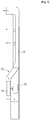
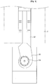
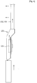
- FIGs. 4 and 5 are views illustrating a ventilating device according to an embodiment of the present invention.
- the ventilating device 120 includes a ventilation fan 124, a first duct 130 and a second duct 140 along which air discharged from the ventilation fan 124 flows, and a scroll 122 in which the ventilation fan 124 is mounted.
- the ventilation fan 124 is configured to suction cool air, cooled by an evaporator, and discharge the cool air into the scroll 122.
- a motor for generating a rotary force is integrally connected to the center of the ventilation fan 124.
- the first duct 130 and the second duct 140 may communicate with the same storage compartment 2 (see FIG. 1 ).
- the first duct 130 and the second duct 140 may communicate with different storage compartments, respectively.
- first duct 130 and the second duct 140 communicate with the same storage compartment
- one end of the first duct 130 communicates with one side of the storage compartment
- one end of the second duct 130 communicates with the other side of the storage compartment opposite to the side where the first duct communicates with the storage compartment, such that lines to supply cool air into the storage compartment are spaced apart from each other.
- a plurality of cool air channels such as the first duct 130 and the second duct 140, communicate with the interior of the storage compartment, whereby the interior of the storage compartment is more uniformly cooled.
- the ventilating device 120 having the first duct 120 and the second duct 140 as the cool air channels extending from the scroll 122 to the storage compartment, is constructed in an optimized structure maximizing the efficiency.
- the present invention provides a ventilating device including a ventilation fan for ventilating air, a first duct for allowing some of the air discharged from the ventilation fan to flow therealong, a second duct for allowing the remaining air, excluding the air discharged from the ventilation fan and flowing along the first duct, to flow therealong, and a scroll for guiding the air discharged from the ventilation fan to the first duct and the second duct, the scroll being constructed in the shape of a spiral track in which a coefficient of expansion angle from a cutoff part to at least one of the first and second ducts is 0.35 to 0.4, whereby the efficiency is maximized.
- FIG. 6 is a view illustrating the ventilating device according to the above-defined embodiment of the present invention.
- the ventilation fan 124 is preferably a centrifugal fan, such as a turbo fan, for suctioning air in the axial direction and then discharging the air in the radial direction.
- a motor for generating a rotary force, may be integrally connected to the center of the ventilation fan 124.
- the first duct 130 and the second duct 140 may communicate with the same storage compartment 2 (see FIG. 1 ). Alternatively, the first duct 130 and the second duct 140 may communicate with different storage compartments, respectively.
- the first duct 130 and the second duct 140 communicate with the same storage compartment
- the first duct 130 and the second duct 140 preferably communicate with opposite sides of the storage compartment.
- the ventilation fan 124 is mounted in the scroll 122. Consequently, when the ventilation fan 124 is operated, air is suctioned in the axial direction of the ventilation fan 124, is discharged in the radial direction of the ventilation fan 124, and is guided to the first duct 130 and the second duct 140 by the scroll 122.
- the scroll 122 is constructed to surround the ventilation fan 124.
- the interior of the scroll 122 is formed in a spiral shape.
- the interior of the scroll 122 communicates with the first duct 130 and the second duct 140. Consequently, the scroll 122 guides the cool air, discharged from the ventilation fan 124, to the first duct 130 and the second duct 140.
- the scroll 122 preferably has a curved part 128 curved along a spiral track from a cutoff forming part 126 to the first duct 130 or the second duct 140.
- the distance r from a center point (in this embodiment, the center point of the ventilation fan 123) to the spiral track is represented by the production of a coefficient of expansion angle a and angle ⁇ from the initial position.
- coefficient of expansion angle is preferably 0.35 to 0.4.
- the air discharged in the radial direction of the ventilation fan 124 smoothly flows to the first duct 130 or the second duct 140 by the scroll 122 curved along the spiral track.
- the angle between a perpendicular line 152 drawn from the center point of the ventilation fan 124 toward the ground and an imaginary straight line 154 interconnecting the center point of the ventilation fan 124 and the cutoff part 126 is 35 to 45 degrees.
- the distance between the outer circumference of the ventilation fan 124 and the cutoff part 126 of the scroll 122 is preferably 3 to 7 % of the diameter D of the ventilation fan 124.
- the distance between the cutoff part 126 of the scroll 122 and the outer circumference of the ventilation fan 124 is preferably 4 to 6 % of the diameter D of the ventilation fan 124.
- FIG. 7 is a graph illustrating the change of power consumption depending upon the change in distance between the cutoff part 126 of the scroll 122 and the outer circumference of the ventilation fan 124.
Landscapes
- Engineering & Computer Science (AREA)
- Mechanical Engineering (AREA)
- General Engineering & Computer Science (AREA)
- Chemical & Material Sciences (AREA)
- Combustion & Propulsion (AREA)
- Physics & Mathematics (AREA)
- Thermal Sciences (AREA)
- Cold Air Circulating Systems And Constructional Details In Refrigerators (AREA)
Claims (1)
- Kühlschrank, der eine Belüftungsvorrichtung aufweist, wobei die Belüftungsvorrichtung Folgendes umfasst:ein Belüftungsgebläse (124) zum Belüften mit Luft;eine erste Leitung (130), damit ein Teil der Luft, die von dem Belüftungsgebläse (124) abgeführt wird, dort entlang strömt;eine zweite Leitung (140), damit die verbleibende Luft abgesehen von der Luft, die von dem Belüftungsgebläse (124) abgeführt wird und entlang der ersten Leitung (130) strömt, dort entlang strömt; undeine Schnecke (122) zum Leiten der Luft, die von dem Belüftungsgebläse (124) abgeführt wird, zu der ersten Leitung (130) und der zweiten Leitung (140), wobei der Innenraum der Schnecke (122) in einer Spiralform gebildet ist,wobei die erste und die zweite Leitung (130,140) einen Abschnitt aufweisen, in dem sie parallel zueinander verlaufen und die Luft in der gleichen Richtung in den zwei Leitungen (130, 140) strömt, undwobei die Drehachse des Gebläses (124) horizontal verläuft und die zwei Leitungen (130, 140) in dem Abschnitt, in dem ihr Verlauf parallel ist, vertikal und von der Schnecke (122) aufwärts verlaufen,wobei das Belüftungsgebläse (124) in der Schnecke (122) angebracht ist und ein Zentrifugalgebläse ist, das die Luft in einer axialen Richtung des Belüftungsgebläses (124) ansaugt und die Luft in einer radialen Richtung von dem Belüftungsgebläse (124) abführt,wobei die erste Leitung (130) und die zweite Leitung (140) an zwei Positionen, die in Umfangsrichtung des Belüftungsgebläses jeweils aneinander angrenzen, mit der Schnecke (122) in Fluidverbindung sind und beide oberhalb der Drehachse des Gebläses liegen,wobei im Querschnitt der Belüftungsvorrichtung durch eine Ebene, die zu der Drehachse des Gebläses senkrecht verläuft, eine vertikale Linie aufwärts von dem Mittelpunkt des Belüftungsgebläses (124) einen Einlass einer der zwei Leitungen (130, 140) schneidet,wobei der Kühlschrank dadurch gekennzeichnet ist, dassdie Schnecke (122) mit einem Aufbau konstruiert ist, bei dem der Abstand zwischen einem abgrenzenden Bauteil (126) und dem Außenumfang des Belüftungsgebläses (124) im Bereich von 2 bis 8 % des Durchmessers des Belüftungsgebläses (124) liegt, und dadurch, dassim Querschnitt der Winkel zwischen der vertikalen Linie und einer imaginären geraden Linie, die den Mittelpunkt des Belüftungsgebläses (124) und das abgrenzende Bauteil verbindet, im Bereich von 35 bis 45 Grad liegt.
Applications Claiming Priority (2)
| Application Number | Priority Date | Filing Date | Title |
|---|---|---|---|
| KR1020070033428A KR100850960B1 (ko) | 2007-04-04 | 2007-04-04 | 송풍장치 및 송풍장치가 구비된 냉장고 |
| PCT/KR2008/000962 WO2008123659A2 (en) | 2007-04-04 | 2008-02-19 | Ventilating device and the refrigerator having the same |
Publications (3)
| Publication Number | Publication Date |
|---|---|
| EP2153145A2 EP2153145A2 (de) | 2010-02-17 |
| EP2153145A4 EP2153145A4 (de) | 2014-07-02 |
| EP2153145B1 true EP2153145B1 (de) | 2018-04-11 |
Family
ID=39831496
Family Applications (1)
| Application Number | Title | Priority Date | Filing Date |
|---|---|---|---|
| EP08712546.4A Not-in-force EP2153145B1 (de) | 2007-04-04 | 2008-02-19 | Lüftungsvorrichtung und kühlschrank damit |
Country Status (4)
| Country | Link |
|---|---|
| US (1) | US20100126207A1 (de) |
| EP (1) | EP2153145B1 (de) |
| KR (1) | KR100850960B1 (de) |
| WO (1) | WO2008123659A2 (de) |
Families Citing this family (5)
| Publication number | Priority date | Publication date | Assignee | Title |
|---|---|---|---|---|
| US9140480B2 (en) | 2013-03-15 | 2015-09-22 | Whirlpool Corporation | Active insulation hybrid dual evaporator with rotating fan |
| DE102016210708A1 (de) * | 2016-06-15 | 2017-12-21 | BSH Hausgeräte GmbH | No-Frost-Kältegerät |
| EP4617594A3 (de) | 2018-03-02 | 2025-11-12 | Electrolux Do Brasil S.A. | Kältegerät mit einem türwärmer |
| WO2020246829A1 (en) | 2019-06-07 | 2020-12-10 | Samsung Electronics Co., Ltd. | Blower and refrigerator |
| KR102585192B1 (ko) * | 2021-11-04 | 2023-10-06 | 엘지전자 주식회사 | 송풍 장치 |
Citations (6)
| Publication number | Priority date | Publication date | Assignee | Title |
|---|---|---|---|---|
| US3027735A (en) * | 1960-01-25 | 1962-04-03 | Gen Motors Corp | Refrigerating apparatus |
| JPS588971A (ja) * | 1981-07-08 | 1983-01-19 | シャープ株式会社 | 冷凍冷蔵庫 |
| DE3840847A1 (de) * | 1987-12-21 | 1989-06-29 | 3P Arredamenti Prizzon S P A | Vorrichtung zur kuehlung, insbesondere von eisbechern |
| KR20020057547A (ko) * | 2001-01-05 | 2002-07-11 | 윤종용 | 냉장고 |
| JP2005036988A (ja) * | 2003-07-15 | 2005-02-10 | Mitsubishi Electric Corp | 冷凍冷蔵庫 |
| EP1857754A2 (de) * | 2006-05-19 | 2007-11-21 | LG Electronics Inc. | Kühlanlage |
Family Cites Families (19)
| Publication number | Priority date | Publication date | Assignee | Title |
|---|---|---|---|---|
| US2341871A (en) * | 1939-07-29 | 1944-02-15 | Oerlikon Maschf | Centrifugal blower with spiral casing |
| US2330938A (en) * | 1941-11-14 | 1943-10-05 | Torrington Mfg Co | Multiple outlet blower assembly |
| US2452185A (en) * | 1946-08-12 | 1948-10-26 | Continental Motors Corp | Fluid pump |
| US2907180A (en) * | 1956-10-19 | 1959-10-06 | Gen Motors Corp | Refrigerating apparatus having air control means for multiple compartments |
| US3050961A (en) * | 1961-05-09 | 1962-08-28 | Gen Motors Corp | Single evaporator two-compartment refrigerator |
| US3472146A (en) * | 1967-08-11 | 1969-10-14 | Ford Motor Co | Fluid pressurizing and distributing apparatus for vehicles |
| DE1951115B2 (de) * | 1969-10-10 | 1976-10-21 | Böhler-Zenkner GmbH & Co KG Strömungstechnik, 4005 Meerbusch | Querstromgeblaese |
| US5531267A (en) * | 1994-08-24 | 1996-07-02 | Emerson Electric Co. | Refrigeration centrifugal blower system |
| JP3632789B2 (ja) * | 1995-08-28 | 2005-03-23 | 東陶機器株式会社 | 多翼遠心ファンの設計方法及び多翼遠心ファン |
| JP3497073B2 (ja) * | 1998-01-19 | 2004-02-16 | 三菱電機株式会社 | 貫流送風機 |
| KR20000005840U (ko) * | 1998-09-03 | 2000-04-06 | 윤종용 | 냉장고 |
| KR100280008B1 (ko) * | 1998-09-14 | 2001-02-01 | 구자홍 | 시로코 팬의 컷오프 |
| JP2001066039A (ja) * | 1999-08-25 | 2001-03-16 | Mitsubishi Electric Corp | 冷蔵庫用送風装置および該冷蔵庫用送風装置を備えた冷蔵庫 |
| KR100378824B1 (ko) * | 2001-04-19 | 2003-04-03 | 엘지전자 주식회사 | 냉장고의 냉기 안내구조 |
| KR200279613Y1 (ko) | 2002-03-26 | 2002-06-24 | 김광민 | 냉동탑차용 송풍기 |
| KR100955574B1 (ko) * | 2003-06-04 | 2010-04-30 | 한라공조주식회사 | 자동차 공조장치용 블로어 유니트의 스크롤 케이스 |
| JP2005083648A (ja) * | 2003-09-08 | 2005-03-31 | Sharp Corp | 流体発生装置 |
| KR101156814B1 (ko) * | 2004-12-27 | 2012-06-18 | 한라공조주식회사 | 송풍기 케이스 |
| KR100768851B1 (ko) * | 2006-05-19 | 2007-10-22 | 엘지전자 주식회사 | 냉장고 |
-
2007
- 2007-04-04 KR KR1020070033428A patent/KR100850960B1/ko not_active Expired - Fee Related
-
2008
- 2008-02-19 WO PCT/KR2008/000962 patent/WO2008123659A2/en not_active Ceased
- 2008-02-19 US US12/594,281 patent/US20100126207A1/en not_active Abandoned
- 2008-02-19 EP EP08712546.4A patent/EP2153145B1/de not_active Not-in-force
Patent Citations (6)
| Publication number | Priority date | Publication date | Assignee | Title |
|---|---|---|---|---|
| US3027735A (en) * | 1960-01-25 | 1962-04-03 | Gen Motors Corp | Refrigerating apparatus |
| JPS588971A (ja) * | 1981-07-08 | 1983-01-19 | シャープ株式会社 | 冷凍冷蔵庫 |
| DE3840847A1 (de) * | 1987-12-21 | 1989-06-29 | 3P Arredamenti Prizzon S P A | Vorrichtung zur kuehlung, insbesondere von eisbechern |
| KR20020057547A (ko) * | 2001-01-05 | 2002-07-11 | 윤종용 | 냉장고 |
| JP2005036988A (ja) * | 2003-07-15 | 2005-02-10 | Mitsubishi Electric Corp | 冷凍冷蔵庫 |
| EP1857754A2 (de) * | 2006-05-19 | 2007-11-21 | LG Electronics Inc. | Kühlanlage |
Also Published As
| Publication number | Publication date |
|---|---|
| EP2153145A2 (de) | 2010-02-17 |
| WO2008123659A3 (en) | 2009-04-02 |
| KR100850960B1 (ko) | 2008-08-08 |
| US20100126207A1 (en) | 2010-05-27 |
| EP2153145A4 (de) | 2014-07-02 |
| WO2008123659A2 (en) | 2008-10-16 |
Similar Documents
| Publication | Publication Date | Title |
|---|---|---|
| JP4741522B2 (ja) | 冷蔵庫 | |
| CN100593674C (zh) | 空调 | |
| CN207471891U (zh) | 鼓风装置及具备该鼓风装置的冰箱 | |
| CN103868306B (zh) | 具有离心风机导管组件的冰箱 | |
| US20080006043A1 (en) | Cool-air supplying apparatus and refrigerator having the same | |
| KR20180054621A (ko) | 휴대용 공조기 | |
| US11933533B2 (en) | Blower and refrigerator | |
| JP2007309633A (ja) | 冷蔵庫 | |
| WO2008040724A2 (en) | A cooling device | |
| US20100126207A1 (en) | Ventilating device and the refrigerator having the same | |
| EP2129981B1 (de) | Kühlluftkanal für speicherkammern einer kühlvorrichtung | |
| KR20090001193U (ko) | 공기조화기의 실외기 | |
| KR20160133733A (ko) | 백연 저감 냉각탑 | |
| CN101630880A (zh) | 冷却压缩机马达的装置 | |
| KR20200140700A (ko) | 송풍 장치 및 냉장고 | |
| EP0697574A2 (de) | Kältegebläseanlage | |
| KR102125720B1 (ko) | 팬 어셈블리 및 이를 구비하는 공기 조화기 | |
| CN222617312U (zh) | 风道组件及具有其的制冷设备 | |
| CN100549585C (zh) | 冷空气供应设备和具有该冷空气供应设备的冰箱 | |
| KR0122439Y1 (ko) | 냉장고 | |
| CN223177765U (zh) | 风机组件、储物设备、热管理系统和车辆 | |
| US7930897B2 (en) | Window type air conditioner | |
| KR20000005840U (ko) | 냉장고 | |
| KR19990012490A (ko) | 냉장고의 냉기 순환장치 | |
| CN119796029A (zh) | 储物设备、热管理系统和车辆 |
Legal Events
| Date | Code | Title | Description |
|---|---|---|---|
| PUAI | Public reference made under article 153(3) epc to a published international application that has entered the european phase |
Free format text: ORIGINAL CODE: 0009012 |
|
| 17P | Request for examination filed |
Effective date: 20090930 |
|
| AK | Designated contracting states |
Kind code of ref document: A2 Designated state(s): AT BE BG CH CY CZ DE DK EE ES FI FR GB GR HR HU IE IS IT LI LT LU LV MC MT NL NO PL PT RO SE SI SK TR |
|
| AX | Request for extension of the european patent |
Extension state: AL BA MK RS |
|
| TPAC | Observations filed by third parties |
Free format text: ORIGINAL CODE: EPIDOSNTIPA |
|
| DAX | Request for extension of the european patent (deleted) | ||
| A4 | Supplementary search report drawn up and despatched |
Effective date: 20140604 |
|
| RIC1 | Information provided on ipc code assigned before grant |
Ipc: F25D 17/06 20060101AFI20140528BHEP Ipc: F04D 29/44 20060101ALI20140528BHEP |
|
| 17Q | First examination report despatched |
Effective date: 20160802 |
|
| STAA | Information on the status of an ep patent application or granted ep patent |
Free format text: STATUS: EXAMINATION IS IN PROGRESS |
|
| GRAP | Despatch of communication of intention to grant a patent |
Free format text: ORIGINAL CODE: EPIDOSNIGR1 |
|
| STAA | Information on the status of an ep patent application or granted ep patent |
Free format text: STATUS: GRANT OF PATENT IS INTENDED |
|
| RIC1 | Information provided on ipc code assigned before grant |
Ipc: F04D 29/44 20060101ALI20171017BHEP Ipc: F25D 17/06 20060101AFI20171017BHEP Ipc: F04D 29/42 20060101ALI20171017BHEP |
|
| INTG | Intention to grant announced |
Effective date: 20171114 |
|
| RAP1 | Party data changed (applicant data changed or rights of an application transferred) |
Owner name: LG ELECTRONICS INC. |
|
| GRAS | Grant fee paid |
Free format text: ORIGINAL CODE: EPIDOSNIGR3 |
|
| GRAA | (expected) grant |
Free format text: ORIGINAL CODE: 0009210 |
|
| STAA | Information on the status of an ep patent application or granted ep patent |
Free format text: STATUS: THE PATENT HAS BEEN GRANTED |
|
| AK | Designated contracting states |
Kind code of ref document: B1 Designated state(s): AT BE BG CH CY CZ DE DK EE ES FI FR GB GR HR HU IE IS IT LI LT LU LV MC MT NL NO PL PT RO SE SI SK TR |
|
| REG | Reference to a national code |
Ref country code: GB Ref legal event code: FG4D |
|
| REG | Reference to a national code |
Ref country code: CH Ref legal event code: EP |
|
| REG | Reference to a national code |
Ref country code: AT Ref legal event code: REF Ref document number: 988479 Country of ref document: AT Kind code of ref document: T Effective date: 20180415 |
|
| REG | Reference to a national code |
Ref country code: IE Ref legal event code: FG4D |
|
| REG | Reference to a national code |
Ref country code: DE Ref legal event code: R096 Ref document number: 602008054765 Country of ref document: DE |
|
| REG | Reference to a national code |
Ref country code: NL Ref legal event code: MP Effective date: 20180411 |
|
| REG | Reference to a national code |
Ref country code: LT Ref legal event code: MG4D |
|
| PG25 | Lapsed in a contracting state [announced via postgrant information from national office to epo] |
Ref country code: NL Free format text: LAPSE BECAUSE OF FAILURE TO SUBMIT A TRANSLATION OF THE DESCRIPTION OR TO PAY THE FEE WITHIN THE PRESCRIBED TIME-LIMIT Effective date: 20180411 |
|
| PG25 | Lapsed in a contracting state [announced via postgrant information from national office to epo] |
Ref country code: ES Free format text: LAPSE BECAUSE OF FAILURE TO SUBMIT A TRANSLATION OF THE DESCRIPTION OR TO PAY THE FEE WITHIN THE PRESCRIBED TIME-LIMIT Effective date: 20180411 Ref country code: SE Free format text: LAPSE BECAUSE OF FAILURE TO SUBMIT A TRANSLATION OF THE DESCRIPTION OR TO PAY THE FEE WITHIN THE PRESCRIBED TIME-LIMIT Effective date: 20180411 Ref country code: LT Free format text: LAPSE BECAUSE OF FAILURE TO SUBMIT A TRANSLATION OF THE DESCRIPTION OR TO PAY THE FEE WITHIN THE PRESCRIBED TIME-LIMIT Effective date: 20180411 Ref country code: PL Free format text: LAPSE BECAUSE OF FAILURE TO SUBMIT A TRANSLATION OF THE DESCRIPTION OR TO PAY THE FEE WITHIN THE PRESCRIBED TIME-LIMIT Effective date: 20180411 Ref country code: FI Free format text: LAPSE BECAUSE OF FAILURE TO SUBMIT A TRANSLATION OF THE DESCRIPTION OR TO PAY THE FEE WITHIN THE PRESCRIBED TIME-LIMIT Effective date: 20180411 Ref country code: NO Free format text: LAPSE BECAUSE OF FAILURE TO SUBMIT A TRANSLATION OF THE DESCRIPTION OR TO PAY THE FEE WITHIN THE PRESCRIBED TIME-LIMIT Effective date: 20180711 Ref country code: BG Free format text: LAPSE BECAUSE OF FAILURE TO SUBMIT A TRANSLATION OF THE DESCRIPTION OR TO PAY THE FEE WITHIN THE PRESCRIBED TIME-LIMIT Effective date: 20180711 |
|
| PG25 | Lapsed in a contracting state [announced via postgrant information from national office to epo] |
Ref country code: LV Free format text: LAPSE BECAUSE OF FAILURE TO SUBMIT A TRANSLATION OF THE DESCRIPTION OR TO PAY THE FEE WITHIN THE PRESCRIBED TIME-LIMIT Effective date: 20180411 Ref country code: GR Free format text: LAPSE BECAUSE OF FAILURE TO SUBMIT A TRANSLATION OF THE DESCRIPTION OR TO PAY THE FEE WITHIN THE PRESCRIBED TIME-LIMIT Effective date: 20180712 Ref country code: HR Free format text: LAPSE BECAUSE OF FAILURE TO SUBMIT A TRANSLATION OF THE DESCRIPTION OR TO PAY THE FEE WITHIN THE PRESCRIBED TIME-LIMIT Effective date: 20180411 |
|
| REG | Reference to a national code |
Ref country code: AT Ref legal event code: MK05 Ref document number: 988479 Country of ref document: AT Kind code of ref document: T Effective date: 20180411 |
|
| PG25 | Lapsed in a contracting state [announced via postgrant information from national office to epo] |
Ref country code: PT Free format text: LAPSE BECAUSE OF FAILURE TO SUBMIT A TRANSLATION OF THE DESCRIPTION OR TO PAY THE FEE WITHIN THE PRESCRIBED TIME-LIMIT Effective date: 20180813 |
|
| REG | Reference to a national code |
Ref country code: DE Ref legal event code: R097 Ref document number: 602008054765 Country of ref document: DE |
|
| PG25 | Lapsed in a contracting state [announced via postgrant information from national office to epo] |
Ref country code: SK Free format text: LAPSE BECAUSE OF FAILURE TO SUBMIT A TRANSLATION OF THE DESCRIPTION OR TO PAY THE FEE WITHIN THE PRESCRIBED TIME-LIMIT Effective date: 20180411 Ref country code: EE Free format text: LAPSE BECAUSE OF FAILURE TO SUBMIT A TRANSLATION OF THE DESCRIPTION OR TO PAY THE FEE WITHIN THE PRESCRIBED TIME-LIMIT Effective date: 20180411 Ref country code: DK Free format text: LAPSE BECAUSE OF FAILURE TO SUBMIT A TRANSLATION OF THE DESCRIPTION OR TO PAY THE FEE WITHIN THE PRESCRIBED TIME-LIMIT Effective date: 20180411 Ref country code: AT Free format text: LAPSE BECAUSE OF FAILURE TO SUBMIT A TRANSLATION OF THE DESCRIPTION OR TO PAY THE FEE WITHIN THE PRESCRIBED TIME-LIMIT Effective date: 20180411 Ref country code: RO Free format text: LAPSE BECAUSE OF FAILURE TO SUBMIT A TRANSLATION OF THE DESCRIPTION OR TO PAY THE FEE WITHIN THE PRESCRIBED TIME-LIMIT Effective date: 20180411 Ref country code: CZ Free format text: LAPSE BECAUSE OF FAILURE TO SUBMIT A TRANSLATION OF THE DESCRIPTION OR TO PAY THE FEE WITHIN THE PRESCRIBED TIME-LIMIT Effective date: 20180411 |
|
| PLBE | No opposition filed within time limit |
Free format text: ORIGINAL CODE: 0009261 |
|
| STAA | Information on the status of an ep patent application or granted ep patent |
Free format text: STATUS: NO OPPOSITION FILED WITHIN TIME LIMIT |
|
| PG25 | Lapsed in a contracting state [announced via postgrant information from national office to epo] |
Ref country code: IT Free format text: LAPSE BECAUSE OF FAILURE TO SUBMIT A TRANSLATION OF THE DESCRIPTION OR TO PAY THE FEE WITHIN THE PRESCRIBED TIME-LIMIT Effective date: 20180411 |
|
| 26N | No opposition filed |
Effective date: 20190114 |
|
| PG25 | Lapsed in a contracting state [announced via postgrant information from national office to epo] |
Ref country code: SI Free format text: LAPSE BECAUSE OF FAILURE TO SUBMIT A TRANSLATION OF THE DESCRIPTION OR TO PAY THE FEE WITHIN THE PRESCRIBED TIME-LIMIT Effective date: 20180411 |
|
| REG | Reference to a national code |
Ref country code: CH Ref legal event code: PL |
|
| GBPC | Gb: european patent ceased through non-payment of renewal fee |
Effective date: 20190219 |
|
| PG25 | Lapsed in a contracting state [announced via postgrant information from national office to epo] |
Ref country code: LU Free format text: LAPSE BECAUSE OF NON-PAYMENT OF DUE FEES Effective date: 20190219 Ref country code: MC Free format text: LAPSE BECAUSE OF FAILURE TO SUBMIT A TRANSLATION OF THE DESCRIPTION OR TO PAY THE FEE WITHIN THE PRESCRIBED TIME-LIMIT Effective date: 20180411 |
|
| REG | Reference to a national code |
Ref country code: BE Ref legal event code: MM Effective date: 20190228 |
|
| REG | Reference to a national code |
Ref country code: IE Ref legal event code: MM4A |
|
| PG25 | Lapsed in a contracting state [announced via postgrant information from national office to epo] |
Ref country code: CH Free format text: LAPSE BECAUSE OF NON-PAYMENT OF DUE FEES Effective date: 20190228 Ref country code: LI Free format text: LAPSE BECAUSE OF NON-PAYMENT OF DUE FEES Effective date: 20190228 |
|
| PG25 | Lapsed in a contracting state [announced via postgrant information from national office to epo] |
Ref country code: IE Free format text: LAPSE BECAUSE OF NON-PAYMENT OF DUE FEES Effective date: 20190219 Ref country code: GB Free format text: LAPSE BECAUSE OF NON-PAYMENT OF DUE FEES Effective date: 20190219 |
|
| PG25 | Lapsed in a contracting state [announced via postgrant information from national office to epo] |
Ref country code: FR Free format text: LAPSE BECAUSE OF NON-PAYMENT OF DUE FEES Effective date: 20190228 Ref country code: BE Free format text: LAPSE BECAUSE OF NON-PAYMENT OF DUE FEES Effective date: 20190228 |
|
| PG25 | Lapsed in a contracting state [announced via postgrant information from national office to epo] |
Ref country code: TR Free format text: LAPSE BECAUSE OF FAILURE TO SUBMIT A TRANSLATION OF THE DESCRIPTION OR TO PAY THE FEE WITHIN THE PRESCRIBED TIME-LIMIT Effective date: 20180411 |
|
| PG25 | Lapsed in a contracting state [announced via postgrant information from national office to epo] |
Ref country code: MT Free format text: LAPSE BECAUSE OF NON-PAYMENT OF DUE FEES Effective date: 20190219 |
|
| PG25 | Lapsed in a contracting state [announced via postgrant information from national office to epo] |
Ref country code: CY Free format text: LAPSE BECAUSE OF FAILURE TO SUBMIT A TRANSLATION OF THE DESCRIPTION OR TO PAY THE FEE WITHIN THE PRESCRIBED TIME-LIMIT Effective date: 20180411 |
|
| PG25 | Lapsed in a contracting state [announced via postgrant information from national office to epo] |
Ref country code: IS Free format text: LAPSE BECAUSE OF FAILURE TO SUBMIT A TRANSLATION OF THE DESCRIPTION OR TO PAY THE FEE WITHIN THE PRESCRIBED TIME-LIMIT Effective date: 20180811 |
|
| PG25 | Lapsed in a contracting state [announced via postgrant information from national office to epo] |
Ref country code: HU Free format text: LAPSE BECAUSE OF FAILURE TO SUBMIT A TRANSLATION OF THE DESCRIPTION OR TO PAY THE FEE WITHIN THE PRESCRIBED TIME-LIMIT; INVALID AB INITIO Effective date: 20080219 |
|
| PGFP | Annual fee paid to national office [announced via postgrant information from national office to epo] |
Ref country code: DE Payment date: 20220105 Year of fee payment: 15 |
|
| REG | Reference to a national code |
Ref country code: DE Ref legal event code: R119 Ref document number: 602008054765 Country of ref document: DE |
|
| PG25 | Lapsed in a contracting state [announced via postgrant information from national office to epo] |
Ref country code: DE Free format text: LAPSE BECAUSE OF NON-PAYMENT OF DUE FEES Effective date: 20230901 |