EP2151663B1 - Système pour focalisation de l'énergie d'une arme à rayons énergétiques - Google Patents
Système pour focalisation de l'énergie d'une arme à rayons énergétiques Download PDFInfo
- Publication number
- EP2151663B1 EP2151663B1 EP09014019.5A EP09014019A EP2151663B1 EP 2151663 B1 EP2151663 B1 EP 2151663B1 EP 09014019 A EP09014019 A EP 09014019A EP 2151663 B1 EP2151663 B1 EP 2151663B1
- Authority
- EP
- European Patent Office
- Prior art keywords
- axis
- focusing
- millimeter
- power
- plane defined
- Prior art date
- Legal status (The legal status is an assumption and is not a legal conclusion. Google has not performed a legal analysis and makes no representation as to the accuracy of the status listed.)
- Not-in-force
Links
- 238000000034 method Methods 0.000 claims description 13
- 230000006870 function Effects 0.000 description 8
- 230000000694 effects Effects 0.000 description 6
- 238000003491 array Methods 0.000 description 4
- 238000013459 approach Methods 0.000 description 3
- 238000001816 cooling Methods 0.000 description 2
- 230000009467 reduction Effects 0.000 description 2
- 238000010521 absorption reaction Methods 0.000 description 1
- 230000008901 benefit Effects 0.000 description 1
- 230000003247 decreasing effect Effects 0.000 description 1
- 230000006872 improvement Effects 0.000 description 1
- 238000002347 injection Methods 0.000 description 1
- 239000007924 injection Substances 0.000 description 1
- 238000012986 modification Methods 0.000 description 1
- 230000004048 modification Effects 0.000 description 1
- 231100001160 nonlethal Toxicity 0.000 description 1
- 230000005855 radiation Effects 0.000 description 1
- 230000035807 sensation Effects 0.000 description 1
Images


Classifications
-
- F—MECHANICAL ENGINEERING; LIGHTING; HEATING; WEAPONS; BLASTING
- F41—WEAPONS
- F41H—ARMOUR; ARMOURED TURRETS; ARMOURED OR ARMED VEHICLES; MEANS OF ATTACK OR DEFENCE, e.g. CAMOUFLAGE, IN GENERAL
- F41H13/00—Means of attack or defence not otherwise provided for
- F41H13/0043—Directed energy weapons, i.e. devices that direct a beam of high energy content toward a target for incapacitating or destroying the target
- F41H13/0068—Directed energy weapons, i.e. devices that direct a beam of high energy content toward a target for incapacitating or destroying the target the high-energy beam being of microwave type, e.g. for causing a heating effect in the target
Definitions
- the present invention generally relates to active denial systems for non-lethal weapons. Specifically, the present invention relates to the use of directed electromagnetic power to generate sufficiently unpleasant sensations in targeted subjects to affect behavior or incapacitate the subject without causing significant physical harm.
- Existing active denial systems involve the use of millimeter-waves, directed onto the subject using a focusing system such as a focusing reflector, lens, flat-panel array antenna, or phased-array system.
- a focusing system such as a focusing reflector, lens, flat-panel array antenna, or phased-array system.
- the properties of these existing focusing systems can be described in terms of a traditional rectangular Cartesian coordinate system, with x, y, and z axes. Where the direction of propagation of a beam is centered along the z-axis, traditional focusing systems cause the beam to converge or diverge approximately equally in both x and y directions. If the beam is converging as it leaves the aperture of the device, it will come to a focus - a plane of minimum extent in x and y - at some particular location along the z-axis. As the beam propagates beyond this point, the beam will diverge.
- the average power density in the beam at any location along the z-direction is given by the total power emitted by the device divided by the effective area of the beam (since the beam intensity will not simply drop to zero at some distance in x or y away from the z-axis, the "boundary" of the beam is usually defined, for example, as the contour at which the intensity of the beam falls to 1/e 2 of its peak intensity along the z-axis).
- the beam In the case in which the beam is converging as it leaves the device aperture, the beam will have a plane of maximum intensity (at the plane of minimum beam area) with decreasing intensity at locations in the z-direction that are either further away from or nearer to the device than the plane of maximum intensity.
- One issue with the variation of intensity with distance along the beam is that there is a range of intensity or power density that is useful in the active denial application. There is a minimum power density below which the subject is not adequately deterred, and a maximum power density above which the beam can cause damage to tissue. Generally, it is preferable that no portion of the beam have an intensity exceeding the damage threshold. The beam will always have a maximum distance beyond which the intensity falls below the effectiveness threshold, but in some configurations in which the beam is converging along both the x and y axes as it leaves the aperture of the apparatus that generates and emits the beam, there will also be a minimum distance from the apparatus within which the beam intensity falls below the effectiveness threshold. Therefore, one must consider the beam intensity with regard to distance from the device for uses such as crowd control or close-range situations.
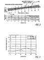
- FIG. 1 (a-d) show beam diameters and power densities as a function of distance of propagation away from the device for several prior art devices having "circular' focusing elements (i.e., that generate beams that depend only upon distance along the z-axis and radial distance away from the z-axis, but not upon angle around planes parallel to the x-y plane).
- FIGS. 1 (a-d) show beam diameters and power densities as a function of distance of propagation away from the device for several prior art devices having "circular' focusing elements (i.e., that generate beams that depend only upon distance along the z-axis and radial distance away from the z-axis, but not upon angle around planes parallel to the x-y plane).
- each beam intensity curve is shown normalized to a peak power density of 1W/cm 2 .
- the associated total power requirements to transmit the beams shown are 3.9kW (per W/cm 2 ) for the collimated beam, and 675W (per W/cm 2 ) for the focused beam.
- FIGS. 1 (c) and (d) show similar plots to those of (a) and (b), but for devices having a 0.3 meter diameter aperture.
- the focused device is configured to place the maximum intensity plane at a distance of 10 meters from the device. Again the curves are normalized to a maximum peak intensity of 1W/cm 2 .
- the associated total power requirements to transmit the beams shown are 360W (per W/cm 2 ) for the collimated beam, and 75W (per W/cm 2 ) for the focused beam.
- the collimated beam requires slightly less than 5 times as much power, but again, the focused beam is likely to fall below effective power densities at distances of less than 5 meters unless dynamic focusing is used.
- the collimated systems have greater "depth of field” (defined here as the range of distance over which the beam maintains a usable power density) than the focused systems, but the collimated systems require much more total output power to reach effective power densities at any distance.
- This disclosure describes approaches to improve the effective depth of field as defined above, while reducing the total output power required to achieve effective power densities over a broader range of distances. These approaches can be combined or used separately.
- US Patent Application Publication No. 2002/0011963 describes a compact, lightweight, steerable, high-power microwave cannon having an antenna for utilization in combination with a vehicle having self-propelled motor means and a power source for providing a pencil-thin beam of high-energy microwave radiation to neutralize electrical circuitry in a target.
- an active denial apparatus comprising a high-power millimeter wave source, and at least one beam-processing element for directing millimeter-wave energy along an axis of propagation, the at least one beam-processing element comprising an astigmatic focusing system configured to direct a focused beam having a focusing profile in a plane defined by a x-axis and a z-axis that includes an axis of propagation, and a substantially different focusing profile in a plane defined by a y-axis and the z-axis also including the axis of propagation that is perpendicular to the x-plane.
- the astigmatic focusing system maybe configured to direct the focused beam with an effective cross-sectional area that is substantially constant over a wide range in the direction of propagation.
- the high-power millimeter-wave source may include a solid-state source, a vacuum tube-based source, a grid amplifier, or a grid oscillator.
- a beam delivered by the variable focusing system may diverge in the plane defined by the x-axis and the z-axis and may converge in the plane defined by the y-axis and the z-axis.
- the at least two focusing configurations may alternate the millimeter wave energy between a plurality of fixed focus settings having either different effective apertures, different effective focal lengths in the plane defined by the x-axis and the z-axis, the plane defined by the y-axis and the z-axis, or both, or both different effective apertures and effective focal lengths.
- the at least two focusing configurations may each be configured to deliver an effective power density within a desired range of power densities over different ranges of distance in an axis of propagation.
- a further aspect of the invention provides a method of focusing energy in an active denial apparatus comprising generating millimeter-wave energy from a high-power millimeter-wave source, and directing the millimeter-wave energy along an axis of propagation, wherein at least one beam processing element for directing the millimeter-wave energy includes an astigmatic focusing system configured to direct a focused beam with a focusing profile in a plane defined by a x-axis and a z-axis, which contains an axis of propagation, the z-axis, and a substantially different focusing profile in a plane defined by a y-axis and the z-axis, which contains the axis of propagation, the z-axis, and is perpendicular to the plane defined by the x-axis and the z-axis,
- the method may further comprise matching a size and a divergence of millimeter waves emanating from the high-power millimeter-wave source to a main reflector to achieve desired beam profiles in the plane defined by the x-axis and the z-axis and the plane defined by the y-axis and the z-axis, the main reflector configured to provide final focusing of the focused beam.
- the directing the millimeter-wave energy along the axis of propagation may further comprise configuring the astigmatic focusing system so that the focusing profile diverges in the plane defined by the x-axis and the z-axis and converges in the plane defined by the y-axis and the z-axis.
- the at least one beam processing element for directing the millimeter-wave energy may include a shaped reflector, a shaped transmissive lens, a flat-panel array antenna, or a phased array system.
- a further aspect of the invention provides an active denial apparatus comprising a high power millimeter-wave source and at least one beam processing element combined in an array having at least one elements that directly generates millimeter-wave energy with a desired set of beam profiles in a plane defined by an x-axis and a z-axis and a plane defined by a y-axis and the z-axis.
- FIG. 2 illustrates the profile of such a beam as a function of distance along the direction of propagation. Note that the x-direction and y-direction need not explicitly denote vertical and horizontal directions, merely two mutually orthogonal directions each orthogonal to the axis of propagation (the z-axis).
- the device can generate peak power densities suitable to generate the active denial effect at different ranges alternately (or sequentially), thereby reducing the peak output power required to generate the effect at each of the distances.
- this technique further reduces the total peak output power requirement.
- the focusing system may comprise a wide range of beam-forming techniques, including, but not limited to, shaped reflective surfaces, transmissive lenses, and arrays of individual radiators, collectively phased to produce a desired wavefront shape.
- the present invention also includes an active denial apparatus comprising a high-power millimeter wave source and at least one beam-processing element for directing millimeter wave energy along an axis of propagation, the at least one beam-processing element including a variable focusing system configured to be cycled through at least two focusing configurations.
- the present invention further includes a method of focusing energy in an active denial apparatus comprising generating millimeter-wave energy from a high-power millimeter-wave source and directing the millimeter-wave energy along an axis of propagation, wherein at least one beam processing element for directing the millimeter-wave energy includes an astigmatic focusing system configured to direct a focused beam with a focusing profile in a plane defined by a x-axis and a z-axis, which contains an axis of propagation, the z-axis, and a substantially different focusing profile in a plane defined by a y-axis and the z-axis, which contains the axis of propagation, the z-axis, and is perpendicular to the plane defined by the x-axis and the z-axis.
- the present invention comprises, according to one embodiment, an active denial apparatus 100 that includes a millimeter-wave source 110 and at least one beam-processing element which comprises an astigmatic or dual-axis focusing system 200.
- the millimeter wave source 110 and the astigmatic focusing system 200 comprise a means for directing millimeter-wave energy to a desired target.
- the at least one beam processing element of the astigmatic or dual-axis focusing system 200 uses a main reflector 210 to provide the final focusing, and a sub-reflector 220 to match the size and divergence of the waves emanating from the millimeter-wave source 110 to the main reflector 210 so as to achieve the desired convergence and divergence of the wave in the x and y directions.
- Application of the astigmatic focusing system 200 to an active denial apparatus 100 in this type of configuration results in a broadening of the depth of focus and therefore an increase in a usable range of the device.
- FIG. 4 shows a side-view cross-section of the focusing elements and the millimeter-wave source 110 in the active denial apparatus 100.
- FIG. 4 shows the configuration of main reflector 210 and sub-reflector 220 according to one embodiment of the present invention.
- Main reflector 210 and sub-reflector 220 may be configured in a variety of different ways to produce different focal lengths.
- these focusing elements may include lenses, flat panel antennas, phased arrays, mirrors, and any other reflective components that allow waves emanating from the millimeter-wave source 110 to achieve the desired convergence and divergence of the wave in the x and y directions.
- the millimeter-wave source 110 may be compact, and could be realized using solid-state grid amplifier and/or grid oscillator technology to obtain a high power beam.
- a useful beam profile can be obtained with the natural divergence of a beam that is collimated in the horizontal direction with a 0.1 meter aperture (i.e., 0.1 meter extent in the x-direction), and converged to a minimum extent in the y-direction at a distance of ⁇ 11 meters using an aperture that extends 0.35 meters in the y-direction.
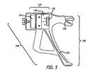
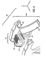
- FIG. 5 shows the active denial apparatus 100 as a handheld unit according to another embodiment of the present invention.
- the astigmatic or dual-axis focusing system 200 described herein can be scaled to any sized system.
- the two main components of the active denial apparatus 100 according to FIG. 5 are the high-power millimeter-wave source 110 and the at least one beam processing element comprising the astigmatic focusing system 200.
- the high-power millimeter wave source 110 comprises a solid-state grid oscillator 130, with an associated heat sink 140 and a cooling fan 150. It is understood that the high-power millimeter-wave source 110 may comprise other types of solid-state or vacuum-tube-based sources.
- Millimeter-wave energy is radiated from the high-power millimeter-wave source 110 to the beam-processing element of the astigmatic focusing system 200.
- the beam processing element comprises a main reflector 210 and a sub-reflector 220, which in the embodiment of FIG. 5 are shaped reflective surfaces. These reflectors 210 and 220 make up the astigmatic or dual-axis focusing system 200 that directs a focused beam with a focusing profile 230 which contains the axis of propagation, the z-axis, in both the xz and yz planes.
- Reflectors 210 and 220 are shaped in such a way such that the focusing profile 230 of the beam in the xz plane is substantially different from the focusing profile 230 of the beam in the yz plane. In the embodiment shown in FIG. 5 , the reflectors 210 and 220 curve very little along one direction, while their curvature in the other direction is much more pronounced. This reflector configuration is the same as that depicted in FIG. 4 , and will give rise to a beam with a near constant cross section over a wide depth of field, as shown in FIG. 3 .
- FIG. 6 is an exploded view of an active denial apparatus 100 employing an astigmatic focusing system 200 according to the present invention. The exploded view of FIG. 6 clearly depicts the multi-reflector configuration discussed above and the solid-state oscillator 130, associated heat sink 140, and cooling fan 150.
- FIG. 3 shows a plot of power density versus distance for a two-setting device having a near-range setting and a far-range setting.
- Each setting uses dual-axis focusing with different aperture sizes and effective focal lengths in both x and y directions. By rapidly alternating between these two settings, the device can produce a nearly constant 1W/cm 2 intensity at 50% duty cycle over a distance from zero to forty meters for every 300W of total output power.
- the ability to alternate the focusing properties between two fixed focus settings having different effective apertures and focal lengths (or sequence through more than two such settings) generates peak power densities suitable to achieve the active denial effect at different ranges alternately (or sequentially) and results in a reduction of the peak output power required to generate the effect at each of the distances.
- the astigmatic focusing system 200 can be configured to broaden the depth of focus in a variety of ways.
- the components of the at least one beam processing element can be selected to direct a focused beam with an effective cross-sectional area that is substantially constant over a wide range in the direction of propagation.
- the at least one beam processing element may be configured so that the focusing profile 230 diverges in the plane defined by the x-axis and the z-axis (the xz-plane) and converges in the plane defined by the y-axis and the z-axis (the yz-plane.)
- the at least one beam processing element may be configured so that the focusing profile 230 converges in both the xz and yz plane.
- the astigmatic focusing system 200 may also be thought of as a variable focusing system configured to include the focusing configurations discussed herein and to be cycled through one or more of those focusing configurations.
- beam processing realized by shaped reflectors can equally be realized using shaped transmissive lenses.
- Alternative embodiments in which the beam processing is realized by a combination of transmissive lenses and shaped reflectors, or realized using only transmissive lenses are also included within the present invention.
- Beam-forming functions can also be performed by array radiators (flat-panel array antennas fed by a single or multiple high-power sources or arrays of active elements such as phased arrays), grid amplifiers, and grid oscillators.
- the phasing of the emission from the array can be such that the array radiates a curved wavefront, with the curvature not constrained to be the same magnitude or sign in the xz-plane and yz-plane.
- FIG. 7 shows an astigmatic focusing system 200 according to one embodiment of the present invention, in which a radiating array 240 can perform all or a portion of the beam processing function, depending on the intended range of the active denial apparatus 100 and the size of the aperture 250.
- the at least one beam processing element may be partially or fully combined with the high power millimeter-wave source 100. Consequently the present invention according to this embodiment contemplates a phased array millimeter-wave source 110, configured in aperture dimensions in the x-direction and y-direction and in effective focal point in the xz-plane and the yz-plane such that a desired beam profiles in the xz-plane and yz-plane are directly generated by the source without need for additional beam processing elements.
- the radiating array 240 of this embodiment of the present invention may be in the form of antenna array elements, and the phased array millimeter wave source 110 may also include a multi-feed flat panel antenna 260, a phasing network 270, and w-band injection locked sources 280.
- the present invention also contemplates a system having two distinct focusing configurations, with two different sets of xz-plane and yz-plane beam profiles. These beam profiles could be optimized to deliver a desired power density range, high enough to be effective and low enough to avoid damage, over two distinct ranges along the axis of propagation (e.g., a range near the aperture of the system and an adjacent range further away). If the system's focal configuration were alternated between the two configurations, the system would alternately be delivering an effective power density to each of the two ranges. Provided the dwell time of the beam in each range and the duty cycle are sufficient to produce the desired effect, such a system can effectively cover both ranges along the axis of propagation.
- Such a system can use a lower peak power than a system that is required to deliver an effective level of power density over both ranges of distance simultaneously, which is a significant advantage.
- An active denial apparatus that can rapidly alternate between two focal configurations may be most simply realized with a system having a focal configuration that is modulated electronically, such as a phased array. Depending on the range requirements of the application, this may be realized using either a variable-focus array with no additional beam processing elements, or using a variable-focus array feeding additional shaped reflectors or lenses
- a system could be configured to cycle through more than two focusing configurations, to further reduce the peak power requirements for the high power millimeter-wave source.
- the millimeter-wave source may comprise other types of energy sources such as other solid-state or vacuum tube-based sources. It is therefore intended that the scope of the invention be limited not by this detailed description.
Landscapes
- Engineering & Computer Science (AREA)
- Radar, Positioning & Navigation (AREA)
- Remote Sensing (AREA)
- General Engineering & Computer Science (AREA)
- Aerials With Secondary Devices (AREA)
- Variable-Direction Aerials And Aerial Arrays (AREA)
- Particle Accelerators (AREA)
- Cold Cathode And The Manufacture (AREA)
- Surgical Instruments (AREA)
Claims (15)
- Appareil d'interdiction active comprenant :une source d'ondes millimétriques haute puissance (110) ; etau moins un élément de traitement de faisceau pour diriger l'énergie des ondes millimétriques le long d'un axe de propagation, caractérisé en ce que l'au moins un élément de traitement de faisceau comprend un système de focalisation variable (200) configuré pour circuler à travers au moins deux configurations de focalisation.
- Appareil d'interdiction active selon la revendication 1, dans lequel un ou plusieurs des au moins deux configurations de focalisation délivre un faisceau ayant une aire de section transversale substantiellement constante sur une large distance le long de l'axe de propagation.
- Appareil d'interdiction active selon la revendication 1, dans lequel un faisceau délivré par le système de focalisation variable (200) diverge dans le plan défini par l'axe x et l'axe z et converge dans le plan défini par l'axe y et l'axe z.
- Appareil d'interdiction active selon la revendication 1, dans lequel les au moins deux configurations de focalisation alternent l'énergie des ondes millimétriques entre une pluralité de réglages de focalisation fixe ayant soit des ouvertures utiles différentes, des distances focales effectives différentes dans le plan défini par l'axe x et l'axe z, le plan défini par l'axe y et l'axe z, ou les deux, soit à la fois des ouvertures utiles et des distances focales effectives différentes.
- Appareil d'interdiction active selon la revendication 1, dans lequel les au moins deux configurations de focalisation sont chacune configurées pour délivrer une densité de puissance effective dans une plage désirée de densité de puissance sur des plages de distance différentes dans un axe de propagation.
- Appareil d'interdiction active selon la revendication 1, dans lequel l'au moins un élément de traitement de faisceau comprend au moins un élément parmi un réflecteur profilé (210, 220), une lentille de transmission profilée, une antenne réseau plane (260) ou un système réseau à commande de phase, ou toute combinaison de ceux-ci.
- Appareil d'interdiction active selon la revendication 1, dans lequel la source d'ondes millimétriques haute puissance (110) comprend au moins un élément parmi une source à état solide ou une source à tubes à vide.
- Appareil d'interdiction active selon la revendication 7, dans lequel si la source d'ondes millimétriques haute puissance (110) inclut une source à l'état solide, alors la source d'ondes millimétriques haute puissance (110) inclut également au moins un élément parmi un amplificateur à grille ou un oscillateur à grille (130), ou toute combinaison de ceux-ci.
- Procédé de focalisation d'énergie dans un appareil d'interdiction active comprenant :générer une énergie d'ondes millimétriques à partir d'une source d'ondes millimétriques haute puissance (110) ; etdiriger l'énergie des ondes millimétriques le long d'un axe de propagation, caractérisé en ce que l'au moins un élément de traitement de faisceau comprend un système de focalisation variable (200) configuré pour circuler à travers au moins deux configurations de focalisation.
- Procédé selon la revendication 9, dans lequel un ou plusieurs des au moins deux configurations de focalisation délivre un faisceau ayant une aire de section transversale substantiellement constante sur une large distance le long de l'axe de propagation.
- Procédé selon la revendication 9, dans lequel un faisceau délivré par le système de focalisation variable (200) diverge dans le plan défini par l'axe x et l'axe z et converge dans le plan défini par l'axe y et l'axe z.
- Procédé selon la revendication 9, dans lequel les au moins deux configurations de focalisation alternent l'énergie des ondes millimétriques entre une pluralité entre une pluralité de réglages de focalisation fixe ayant soit des ouvertures utiles différentes, des distances focales effectives différentes dans le plan défini par l'axe x et l'axe z, le plan défini par l'axe y et l'axe z, ou les deux, soit à la fois des ouvertures utiles et des distances focales effectives différentes.
- Procédé selon la revendication 9, dans lequel les au moins deux configurations de focalisation sont chacune configurées pour délivrer une densité de puissance effective dans une plage désirée de densité de puissance sur des plages de distance différentes dans un axe de propagation.
- Procédé selon la revendication 9, dans lequel l'au moins un élément de traitement de faisceau comprend au moins un élément parmi un réflecteur profilé (210), une lentille de transmission profilée, une antenne réseau plane (260) ou un système réseau à commande de phase, ou toute combinaison de ceux-ci.
- Procédé selon la revendication 9, dans lequel la source d'ondes millimétriques haute puissance (110) comprend au moins un élément parmi une source à état solide ou une source à tubes à vide.
Applications Claiming Priority (2)
| Application Number | Priority Date | Filing Date | Title |
|---|---|---|---|
| US90231907P | 2007-02-20 | 2007-02-20 | |
| EP08725795.2A EP2113063B1 (fr) | 2007-02-20 | 2008-02-20 | Système de focalisation d'énergie pour appareil d'interdiction active |
Related Parent Applications (2)
| Application Number | Title | Priority Date | Filing Date |
|---|---|---|---|
| EP08725795.2A Division EP2113063B1 (fr) | 2007-02-20 | 2008-02-20 | Système de focalisation d'énergie pour appareil d'interdiction active |
| EP08725795.2 Division | 2008-02-20 |
Publications (3)
| Publication Number | Publication Date |
|---|---|
| EP2151663A2 EP2151663A2 (fr) | 2010-02-10 |
| EP2151663A3 EP2151663A3 (fr) | 2011-10-05 |
| EP2151663B1 true EP2151663B1 (fr) | 2013-12-11 |
Family
ID=39710379
Family Applications (2)
| Application Number | Title | Priority Date | Filing Date |
|---|---|---|---|
| EP09014019.5A Not-in-force EP2151663B1 (fr) | 2007-02-20 | 2008-02-20 | Système pour focalisation de l'énergie d'une arme à rayons énergétiques |
| EP08725795.2A Not-in-force EP2113063B1 (fr) | 2007-02-20 | 2008-02-20 | Système de focalisation d'énergie pour appareil d'interdiction active |
Family Applications After (1)
| Application Number | Title | Priority Date | Filing Date |
|---|---|---|---|
| EP08725795.2A Not-in-force EP2113063B1 (fr) | 2007-02-20 | 2008-02-20 | Système de focalisation d'énergie pour appareil d'interdiction active |
Country Status (8)
| Country | Link |
|---|---|
| US (2) | US8453551B2 (fr) |
| EP (2) | EP2151663B1 (fr) |
| JP (1) | JP2010519499A (fr) |
| AU (1) | AU2008219083A1 (fr) |
| CA (1) | CA2678741A1 (fr) |
| IL (1) | IL200491A0 (fr) |
| MX (1) | MX2009008905A (fr) |
| WO (1) | WO2008103363A1 (fr) |
Families Citing this family (13)
| Publication number | Priority date | Publication date | Assignee | Title |
|---|---|---|---|---|
| MX2012012706A (es) | 2010-05-03 | 2013-04-29 | Goji Ltd | Analisis modal. |
| JP6041648B2 (ja) * | 2012-12-03 | 2016-12-14 | 三菱重工業株式会社 | 指向性エネルギー照射装置 |
| CN103256857B (zh) * | 2013-05-17 | 2015-09-30 | 广州圣弦能源科技有限公司 | 一种集束电磁波发射器 |
| CN103759580B (zh) * | 2014-01-20 | 2015-08-12 | 成都华之芯科技有限公司 | 一种有源拒止系统 |
| CN103970014A (zh) * | 2014-05-04 | 2014-08-06 | 成都华之芯科技有限公司 | 极高频制动系统及自适应波形控制策略 |
| CN103970015B (zh) * | 2014-05-04 | 2017-09-01 | 成都华之芯科技有限公司 | 一种极高频制动系统及其场景自适应波形控制方法 |
| CN105783589B (zh) * | 2016-05-17 | 2017-12-26 | 长乐芯聚电子科技研究所 | 脉冲集束能武器 |
| WO2020107006A1 (fr) * | 2018-11-21 | 2020-05-28 | Frederick Newton | Procédés et appareil pour un système de défense de zone publique |
| US11741807B2 (en) | 2018-11-21 | 2023-08-29 | Frederick Lee Newton | Methods and apparatus for a public area defense system |
| WO2020160055A1 (fr) | 2019-01-28 | 2020-08-06 | Frederick Lee Newton | Procédés et appareil pour armes non létales |
| DE202022000442U1 (de) | 2022-02-22 | 2022-05-18 | Benno Fronrobert | Drohnenfahrzeug |
| US11801394B1 (en) | 2023-01-10 | 2023-10-31 | Elwood Norris | Systems and methods for covertly creating adverse health effects in subjects |
| US12540803B2 (en) | 2023-07-24 | 2026-02-03 | Raytheon Company | Tactical high power microwave antenna pedestal |
Family Cites Families (24)
| Publication number | Priority date | Publication date | Assignee | Title |
|---|---|---|---|---|
| US4339757A (en) * | 1980-11-24 | 1982-07-13 | Bell Telephone Laboratories, Incorporated | Broadband astigmatic feed arrangement for an antenna |
| US4553068A (en) * | 1983-10-26 | 1985-11-12 | The United States Of America As Represented By The Secretary Of The Army | High power millimeter-wave source |
| ES2023680B3 (es) * | 1987-03-03 | 1992-02-01 | Centre De Rech En Physique Des Plasmas | Girotron de alto rendimiento para obtencion de ondas electromagneticas milimetricas o submilimetricas |
| DE68913668T2 (de) * | 1988-12-05 | 1994-06-16 | Euratom | Milimeterwellen-Antenne zur Erzeugung eines Strahles mit einer Gauss-Verteilung. |
| US5317173A (en) * | 1993-05-13 | 1994-05-31 | Rockwell International Corporation | HBT differential pair chip for quasi-optic amplifiers |
| US5734303A (en) * | 1994-03-11 | 1998-03-31 | The United States Of America As Represented By The Secretary Of The Air Force | Microwave waveguide mode converter having a bevel output end |
| US5422596A (en) * | 1994-06-30 | 1995-06-06 | The United States Of America As Represented By The Secretary Of The Navy | High power, broadband folded waveguide gyrotron-traveling-wave-amplifier |
| US5777572A (en) * | 1994-07-19 | 1998-07-07 | Northrop Grumman Corporation | Device for damaging electronic equipment using unfocussed high power millimeter wave beams |
| DE4444636A1 (de) * | 1994-12-15 | 1996-06-20 | Sepp Gunther | Waffensystem für einen Blendlaser |
| US5685636A (en) * | 1995-08-23 | 1997-11-11 | Science And Engineering Associates, Inc. | Eye safe laser security device |
| JP3602259B2 (ja) * | 1996-05-02 | 2004-12-15 | 本田技研工業株式会社 | マルチビーム・レーダ装置 |
| JP2000049524A (ja) * | 1998-07-31 | 2000-02-18 | Nec Corp | アレイアンテナ |
| EP1295356B1 (fr) * | 2000-06-13 | 2006-10-18 | California Institute of Technology | Adaptateur guide d'ondes de translation de modes pour grille quasi-optique |
| US6559807B2 (en) * | 2000-07-26 | 2003-05-06 | Scientific Applications & Research Associates, Inc. | Compact, lightweight, steerable, high-power microwave antenna |
| JP3892718B2 (ja) * | 2001-12-14 | 2007-03-14 | 株式会社日立国際電気 | レーザ送信器 |
| JP3981608B2 (ja) * | 2002-08-08 | 2007-09-26 | 東芝電波プロダクツ株式会社 | デュアルビーム光学装置 |
| US6766793B2 (en) * | 2002-12-12 | 2004-07-27 | General Atomics | Electromagnetic gun and rotating pulse forming network |
| US6950021B2 (en) * | 2003-09-23 | 2005-09-27 | Walker Butler | Electronic wall using high-resolution millimeter-wave radar in conjunction with multiple plane reflectors and retroreflectors |
| US7126477B2 (en) * | 2004-01-15 | 2006-10-24 | Raytheon Company | Millimeter-wave area-protection system and method |
| US7180426B2 (en) * | 2004-11-19 | 2007-02-20 | Optech Ventures, Llc | Incapacitating flashing light apparatus and method |
| FR2881532B1 (fr) * | 2005-02-01 | 2007-05-18 | Commissariat Energie Atomique | Procede de mise en oeuvre d'un ensemble rayonnant de puissance ayant une portee kilometrique |
| US7490538B2 (en) * | 2005-08-18 | 2009-02-17 | Raytheon Company | Weapon having lethal and non-lethal directed-energy portions |
| US7629918B2 (en) * | 2005-12-15 | 2009-12-08 | Raytheon Company | Multifunctional radio frequency directed energy system |
| US7633425B2 (en) * | 2007-11-16 | 2009-12-15 | Ratheon Company | Waveguide system comprising reflective surfaces for directing a wave beam to a target |
-
2008
- 2008-02-20 US US12/070,801 patent/US8453551B2/en not_active Expired - Fee Related
- 2008-02-20 WO PCT/US2008/002199 patent/WO2008103363A1/fr not_active Ceased
- 2008-02-20 CA CA002678741A patent/CA2678741A1/fr not_active Abandoned
- 2008-02-20 EP EP09014019.5A patent/EP2151663B1/fr not_active Not-in-force
- 2008-02-20 EP EP08725795.2A patent/EP2113063B1/fr not_active Not-in-force
- 2008-02-20 JP JP2009550901A patent/JP2010519499A/ja not_active Ceased
- 2008-02-20 AU AU2008219083A patent/AU2008219083A1/en not_active Abandoned
- 2008-02-20 MX MX2009008905A patent/MX2009008905A/es not_active Application Discontinuation
-
2009
- 2009-08-19 IL IL200491A patent/IL200491A0/en unknown
-
2011
- 2011-12-16 US US13/374,227 patent/US8661961B2/en active Active
Also Published As
| Publication number | Publication date |
|---|---|
| MX2009008905A (es) | 2009-08-28 |
| EP2113063A1 (fr) | 2009-11-04 |
| US20120097867A1 (en) | 2012-04-26 |
| EP2151663A2 (fr) | 2010-02-10 |
| AU2008219083A1 (en) | 2008-08-28 |
| US8661961B2 (en) | 2014-03-04 |
| EP2151663A3 (fr) | 2011-10-05 |
| IL200491A0 (en) | 2010-04-29 |
| EP2113063B1 (fr) | 2013-04-24 |
| US8453551B2 (en) | 2013-06-04 |
| CA2678741A1 (fr) | 2008-08-28 |
| JP2010519499A (ja) | 2010-06-03 |
| EP2113063A4 (fr) | 2011-12-28 |
| WO2008103363A1 (fr) | 2008-08-28 |
| US20100282985A1 (en) | 2010-11-11 |
Similar Documents
| Publication | Publication Date | Title |
|---|---|---|
| EP2151663B1 (fr) | Système pour focalisation de l'énergie d'une arme à rayons énergétiques | |
| US7490538B2 (en) | Weapon having lethal and non-lethal directed-energy portions | |
| US8810468B2 (en) | Beam shaping of RF feed energy for reflector-based antennas | |
| JP5290403B2 (ja) | 和−差方位識別技法を用いる小開口呼び掛け機アンテナシステム | |
| US20030160724A1 (en) | Plasma filter antenna system | |
| EP2835868B1 (fr) | Antenne | |
| US20170229786A1 (en) | Antenna System and Processing Method | |
| US11194015B2 (en) | High-power electromagnetic source, vehicle and method | |
| JP2011244440A (ja) | 広角マルチビーム | |
| CN112134001A (zh) | 一种w波段方向图可重构的赋形面天线及系统 | |
| US11067665B2 (en) | Aircraft radar assembly | |
| JP6337171B1 (ja) | アンテナ装置 | |
| US8472121B2 (en) | Adjustable electromagnetic energy collimator | |
| US8134510B2 (en) | Coherent near-field array | |
| RU2319261C1 (ru) | Радиолокационная антенна с уменьшенной эффективной площадью рассеяния | |
| RU2642515C2 (ru) | Способ формирования эллиптической диаграммы направленности для активной фазированной антенной решетки | |
| Ze-Ming et al. | An improved array feed parabolic reflector antenna for spatial power combining | |
| RU2644618C2 (ru) | Устройство формирования и излучения мощных радиоимпульсов | |
| WO2023203752A1 (fr) | Réflecteur d'antenne et couvercle de dispositif de communication sans fil | |
| JP2023090698A (ja) | アレイアンテナの広域スキャン能力を向上させる光学システム | |
| Tummala et al. | Synthesis of hexagonal antenna array using firefly algorithm | |
| Ahsan et al. | Designing shaped dual reflector antenna system by ray tracing method | |
| Niu et al. | Effect of geometrical parameters on beam scanning characteristics of reflector antennas | |
| Amanowicz et al. | Highly effective asymmetric reflector antennas of Cassegrain type |
Legal Events
| Date | Code | Title | Description |
|---|---|---|---|
| PUAI | Public reference made under article 153(3) epc to a published international application that has entered the european phase |
Free format text: ORIGINAL CODE: 0009012 |
|
| AC | Divisional application: reference to earlier application |
Ref document number: 2113063 Country of ref document: EP Kind code of ref document: P |
|
| AK | Designated contracting states |
Kind code of ref document: A2 Designated state(s): AT BE BG CH CY CZ DE DK EE ES FI FR GB GR HR HU IE IS IT LI LT LU LV MC MT NL NO PL PT RO SE SI SK TR |
|
| AX | Request for extension of the european patent |
Extension state: AL BA MK RS |
|
| RTI1 | Title (correction) |
Free format text: ENERGY FOCUSING SYSTEM FOR ENERGY BEAM WEAPON |
|
| RIN1 | Information on inventor provided before grant (corrected) |
Inventor name: ROSENBERG, JAMES JORDAN Inventor name: ARONSON, MICHAEL LOREN Inventor name: DELISO, MICHAEL PETER, JR. Inventor name: DECKMAN, BLYTHE CHADWICK |
|
| PUAL | Search report despatched |
Free format text: ORIGINAL CODE: 0009013 |
|
| AK | Designated contracting states |
Kind code of ref document: A3 Designated state(s): AT BE BG CH CY CZ DE DK EE ES FI FR GB GR HR HU IE IS IT LI LT LU LV MC MT NL NO PL PT RO SE SI SK TR |
|
| AX | Request for extension of the european patent |
Extension state: AL BA MK RS |
|
| RIC1 | Information provided on ipc code assigned before grant |
Ipc: F41H 13/00 20060101AFI20110829BHEP |
|
| 17P | Request for examination filed |
Effective date: 20120402 |
|
| 17Q | First examination report despatched |
Effective date: 20120730 |
|
| GRAP | Despatch of communication of intention to grant a patent |
Free format text: ORIGINAL CODE: EPIDOSNIGR1 |
|
| GRAS | Grant fee paid |
Free format text: ORIGINAL CODE: EPIDOSNIGR3 |
|
| GRAP | Despatch of communication of intention to grant a patent |
Free format text: ORIGINAL CODE: EPIDOSNIGR1 |
|
| INTG | Intention to grant announced |
Effective date: 20130730 |
|
| GRAA | (expected) grant |
Free format text: ORIGINAL CODE: 0009210 |
|
| RIN1 | Information on inventor provided before grant (corrected) |
Inventor name: ROSENBERG, JAMES JORDAN Inventor name: DELISIO, MICHAEL PETER, JR. Inventor name: DECKMAN, BLYTHE CHADWICK Inventor name: ARONSON, MICHAEL LOREN |
|
| AC | Divisional application: reference to earlier application |
Ref document number: 2113063 Country of ref document: EP Kind code of ref document: P |
|
| AK | Designated contracting states |
Kind code of ref document: B1 Designated state(s): AT BE BG CH CY CZ DE DK EE ES FI FR GB GR HR HU IE IS IT LI LT LU LV MC MT NL NO PL PT RO SE SI SK TR |
|
| REG | Reference to a national code |
Ref country code: GB Ref legal event code: FG4D |
|
| REG | Reference to a national code |
Ref country code: CH Ref legal event code: EP |
|
| REG | Reference to a national code |
Ref country code: AT Ref legal event code: REF Ref document number: 644810 Country of ref document: AT Kind code of ref document: T Effective date: 20140115 |
|
| REG | Reference to a national code |
Ref country code: IE Ref legal event code: FG4D |
|
| REG | Reference to a national code |
Ref country code: DE Ref legal event code: R096 Ref document number: 602008029333 Country of ref document: DE Effective date: 20140206 |
|
| REG | Reference to a national code |
Ref country code: NL Ref legal event code: VDEP Effective date: 20131211 |
|
| REG | Reference to a national code |
Ref country code: AT Ref legal event code: MK05 Ref document number: 644810 Country of ref document: AT Kind code of ref document: T Effective date: 20131211 |
|
| PG25 | Lapsed in a contracting state [announced via postgrant information from national office to epo] |
Ref country code: LT Free format text: LAPSE BECAUSE OF FAILURE TO SUBMIT A TRANSLATION OF THE DESCRIPTION OR TO PAY THE FEE WITHIN THE PRESCRIBED TIME-LIMIT Effective date: 20131211 Ref country code: SE Free format text: LAPSE BECAUSE OF FAILURE TO SUBMIT A TRANSLATION OF THE DESCRIPTION OR TO PAY THE FEE WITHIN THE PRESCRIBED TIME-LIMIT Effective date: 20131211 Ref country code: HR Free format text: LAPSE BECAUSE OF FAILURE TO SUBMIT A TRANSLATION OF THE DESCRIPTION OR TO PAY THE FEE WITHIN THE PRESCRIBED TIME-LIMIT Effective date: 20131211 Ref country code: FI Free format text: LAPSE BECAUSE OF FAILURE TO SUBMIT A TRANSLATION OF THE DESCRIPTION OR TO PAY THE FEE WITHIN THE PRESCRIBED TIME-LIMIT Effective date: 20131211 Ref country code: NL Free format text: LAPSE BECAUSE OF FAILURE TO SUBMIT A TRANSLATION OF THE DESCRIPTION OR TO PAY THE FEE WITHIN THE PRESCRIBED TIME-LIMIT Effective date: 20131211 Ref country code: NO Free format text: LAPSE BECAUSE OF FAILURE TO SUBMIT A TRANSLATION OF THE DESCRIPTION OR TO PAY THE FEE WITHIN THE PRESCRIBED TIME-LIMIT Effective date: 20140311 |
|
| REG | Reference to a national code |
Ref country code: LT Ref legal event code: MG4D |
|
| PG25 | Lapsed in a contracting state [announced via postgrant information from national office to epo] |
Ref country code: LV Free format text: LAPSE BECAUSE OF FAILURE TO SUBMIT A TRANSLATION OF THE DESCRIPTION OR TO PAY THE FEE WITHIN THE PRESCRIBED TIME-LIMIT Effective date: 20131211 Ref country code: AT Free format text: LAPSE BECAUSE OF FAILURE TO SUBMIT A TRANSLATION OF THE DESCRIPTION OR TO PAY THE FEE WITHIN THE PRESCRIBED TIME-LIMIT Effective date: 20131211 Ref country code: CY Free format text: LAPSE BECAUSE OF FAILURE TO SUBMIT A TRANSLATION OF THE DESCRIPTION OR TO PAY THE FEE WITHIN THE PRESCRIBED TIME-LIMIT Effective date: 20131211 |
|
| PG25 | Lapsed in a contracting state [announced via postgrant information from national office to epo] |
Ref country code: IS Free format text: LAPSE BECAUSE OF FAILURE TO SUBMIT A TRANSLATION OF THE DESCRIPTION OR TO PAY THE FEE WITHIN THE PRESCRIBED TIME-LIMIT Effective date: 20140411 Ref country code: BE Free format text: LAPSE BECAUSE OF FAILURE TO SUBMIT A TRANSLATION OF THE DESCRIPTION OR TO PAY THE FEE WITHIN THE PRESCRIBED TIME-LIMIT Effective date: 20131211 Ref country code: EE Free format text: LAPSE BECAUSE OF FAILURE TO SUBMIT A TRANSLATION OF THE DESCRIPTION OR TO PAY THE FEE WITHIN THE PRESCRIBED TIME-LIMIT Effective date: 20131211 |
|
| PG25 | Lapsed in a contracting state [announced via postgrant information from national office to epo] |
Ref country code: SK Free format text: LAPSE BECAUSE OF FAILURE TO SUBMIT A TRANSLATION OF THE DESCRIPTION OR TO PAY THE FEE WITHIN THE PRESCRIBED TIME-LIMIT Effective date: 20131211 Ref country code: CZ Free format text: LAPSE BECAUSE OF FAILURE TO SUBMIT A TRANSLATION OF THE DESCRIPTION OR TO PAY THE FEE WITHIN THE PRESCRIBED TIME-LIMIT Effective date: 20131211 Ref country code: PT Free format text: LAPSE BECAUSE OF FAILURE TO SUBMIT A TRANSLATION OF THE DESCRIPTION OR TO PAY THE FEE WITHIN THE PRESCRIBED TIME-LIMIT Effective date: 20140411 Ref country code: RO Free format text: LAPSE BECAUSE OF FAILURE TO SUBMIT A TRANSLATION OF THE DESCRIPTION OR TO PAY THE FEE WITHIN THE PRESCRIBED TIME-LIMIT Effective date: 20131211 Ref country code: PL Free format text: LAPSE BECAUSE OF FAILURE TO SUBMIT A TRANSLATION OF THE DESCRIPTION OR TO PAY THE FEE WITHIN THE PRESCRIBED TIME-LIMIT Effective date: 20131211 Ref country code: ES Free format text: LAPSE BECAUSE OF FAILURE TO SUBMIT A TRANSLATION OF THE DESCRIPTION OR TO PAY THE FEE WITHIN THE PRESCRIBED TIME-LIMIT Effective date: 20131211 |
|
| REG | Reference to a national code |
Ref country code: DE Ref legal event code: R097 Ref document number: 602008029333 Country of ref document: DE |
|
| PG25 | Lapsed in a contracting state [announced via postgrant information from national office to epo] |
Ref country code: MC Free format text: LAPSE BECAUSE OF FAILURE TO SUBMIT A TRANSLATION OF THE DESCRIPTION OR TO PAY THE FEE WITHIN THE PRESCRIBED TIME-LIMIT Effective date: 20131211 Ref country code: LU Free format text: LAPSE BECAUSE OF FAILURE TO SUBMIT A TRANSLATION OF THE DESCRIPTION OR TO PAY THE FEE WITHIN THE PRESCRIBED TIME-LIMIT Effective date: 20140220 |
|
| REG | Reference to a national code |
Ref country code: CH Ref legal event code: PL |
|
| PLBE | No opposition filed within time limit |
Free format text: ORIGINAL CODE: 0009261 |
|
| STAA | Information on the status of an ep patent application or granted ep patent |
Free format text: STATUS: NO OPPOSITION FILED WITHIN TIME LIMIT |
|
| PG25 | Lapsed in a contracting state [announced via postgrant information from national office to epo] |
Ref country code: LI Free format text: LAPSE BECAUSE OF NON-PAYMENT OF DUE FEES Effective date: 20140228 Ref country code: DK Free format text: LAPSE BECAUSE OF FAILURE TO SUBMIT A TRANSLATION OF THE DESCRIPTION OR TO PAY THE FEE WITHIN THE PRESCRIBED TIME-LIMIT Effective date: 20131211 Ref country code: CH Free format text: LAPSE BECAUSE OF NON-PAYMENT OF DUE FEES Effective date: 20140228 |
|
| 26N | No opposition filed |
Effective date: 20140912 |
|
| REG | Reference to a national code |
Ref country code: IE Ref legal event code: MM4A |
|
| REG | Reference to a national code |
Ref country code: DE Ref legal event code: R097 Ref document number: 602008029333 Country of ref document: DE Effective date: 20140912 |
|
| PG25 | Lapsed in a contracting state [announced via postgrant information from national office to epo] |
Ref country code: IE Free format text: LAPSE BECAUSE OF NON-PAYMENT OF DUE FEES Effective date: 20140220 |
|
| PG25 | Lapsed in a contracting state [announced via postgrant information from national office to epo] |
Ref country code: SI Free format text: LAPSE BECAUSE OF FAILURE TO SUBMIT A TRANSLATION OF THE DESCRIPTION OR TO PAY THE FEE WITHIN THE PRESCRIBED TIME-LIMIT Effective date: 20131211 |
|
| REG | Reference to a national code |
Ref country code: FR Ref legal event code: PLFP Year of fee payment: 9 |
|
| PG25 | Lapsed in a contracting state [announced via postgrant information from national office to epo] |
Ref country code: MT Free format text: LAPSE BECAUSE OF FAILURE TO SUBMIT A TRANSLATION OF THE DESCRIPTION OR TO PAY THE FEE WITHIN THE PRESCRIBED TIME-LIMIT Effective date: 20131211 |
|
| PG25 | Lapsed in a contracting state [announced via postgrant information from national office to epo] |
Ref country code: BG Free format text: LAPSE BECAUSE OF FAILURE TO SUBMIT A TRANSLATION OF THE DESCRIPTION OR TO PAY THE FEE WITHIN THE PRESCRIBED TIME-LIMIT Effective date: 20131211 |
|
| PG25 | Lapsed in a contracting state [announced via postgrant information from national office to epo] |
Ref country code: GR Free format text: LAPSE BECAUSE OF FAILURE TO SUBMIT A TRANSLATION OF THE DESCRIPTION OR TO PAY THE FEE WITHIN THE PRESCRIBED TIME-LIMIT Effective date: 20140312 Ref country code: IT Free format text: LAPSE BECAUSE OF FAILURE TO SUBMIT A TRANSLATION OF THE DESCRIPTION OR TO PAY THE FEE WITHIN THE PRESCRIBED TIME-LIMIT Effective date: 20131211 |
|
| PG25 | Lapsed in a contracting state [announced via postgrant information from national office to epo] |
Ref country code: TR Free format text: LAPSE BECAUSE OF FAILURE TO SUBMIT A TRANSLATION OF THE DESCRIPTION OR TO PAY THE FEE WITHIN THE PRESCRIBED TIME-LIMIT Effective date: 20131211 Ref country code: HU Free format text: LAPSE BECAUSE OF FAILURE TO SUBMIT A TRANSLATION OF THE DESCRIPTION OR TO PAY THE FEE WITHIN THE PRESCRIBED TIME-LIMIT; INVALID AB INITIO Effective date: 20080220 |
|
| REG | Reference to a national code |
Ref country code: FR Ref legal event code: PLFP Year of fee payment: 10 |
|
| REG | Reference to a national code |
Ref country code: FR Ref legal event code: PLFP Year of fee payment: 11 |
|
| PGFP | Annual fee paid to national office [announced via postgrant information from national office to epo] |
Ref country code: GB Payment date: 20221230 Year of fee payment: 16 |
|
| PGFP | Annual fee paid to national office [announced via postgrant information from national office to epo] |
Ref country code: FR Payment date: 20230110 Year of fee payment: 16 |
|
| PGFP | Annual fee paid to national office [announced via postgrant information from national office to epo] |
Ref country code: DE Payment date: 20221229 Year of fee payment: 16 |
|
| REG | Reference to a national code |
Ref country code: DE Ref legal event code: R119 Ref document number: 602008029333 Country of ref document: DE |
|
| GBPC | Gb: european patent ceased through non-payment of renewal fee |
Effective date: 20240220 |
|
| PG25 | Lapsed in a contracting state [announced via postgrant information from national office to epo] |
Ref country code: DE Free format text: LAPSE BECAUSE OF NON-PAYMENT OF DUE FEES Effective date: 20240903 |
|
| PG25 | Lapsed in a contracting state [announced via postgrant information from national office to epo] |
Ref country code: GB Free format text: LAPSE BECAUSE OF NON-PAYMENT OF DUE FEES Effective date: 20240220 |
|
| PG25 | Lapsed in a contracting state [announced via postgrant information from national office to epo] |
Ref country code: FR Free format text: LAPSE BECAUSE OF NON-PAYMENT OF DUE FEES Effective date: 20240229 |
|
| PG25 | Lapsed in a contracting state [announced via postgrant information from national office to epo] |
Ref country code: GB Free format text: LAPSE BECAUSE OF NON-PAYMENT OF DUE FEES Effective date: 20240220 Ref country code: FR Free format text: LAPSE BECAUSE OF NON-PAYMENT OF DUE FEES Effective date: 20240229 Ref country code: DE Free format text: LAPSE BECAUSE OF NON-PAYMENT OF DUE FEES Effective date: 20240903 |