EP2151518A2 - Trommelwaschmaschine - Google Patents
Trommelwaschmaschine Download PDFInfo
- Publication number
- EP2151518A2 EP2151518A2 EP09158891A EP09158891A EP2151518A2 EP 2151518 A2 EP2151518 A2 EP 2151518A2 EP 09158891 A EP09158891 A EP 09158891A EP 09158891 A EP09158891 A EP 09158891A EP 2151518 A2 EP2151518 A2 EP 2151518A2
- Authority
- EP
- European Patent Office
- Prior art keywords
- cap
- controller
- water
- reed switch
- drain
- Prior art date
- Legal status (The legal status is an assumption and is not a legal conclusion. Google has not performed a legal analysis and makes no representation as to the accuracy of the status listed.)
- Granted
Links
- 238000005406 washing Methods 0.000 title claims abstract description 115
- XLYOFNOQVPJJNP-UHFFFAOYSA-N water Substances O XLYOFNOQVPJJNP-UHFFFAOYSA-N 0.000 claims abstract description 93
- 238000000034 method Methods 0.000 claims abstract description 64
- 235000014676 Phragmites communis Nutrition 0.000 claims abstract description 56
- 230000009849 deactivation Effects 0.000 claims abstract description 32
- 230000004913 activation Effects 0.000 claims abstract description 31
- 238000007789 sealing Methods 0.000 claims abstract description 9
- 239000002245 particle Substances 0.000 claims description 17
- 238000007599 discharging Methods 0.000 claims description 7
- 101150114468 TUB1 gene Proteins 0.000 description 14
- 238000001035 drying Methods 0.000 description 7
- 238000009434 installation Methods 0.000 description 4
- 230000005856 abnormality Effects 0.000 description 2
- 239000013013 elastic material Substances 0.000 description 2
- 239000000463 material Substances 0.000 description 2
- 238000000465 moulding Methods 0.000 description 2
- 239000011347 resin Substances 0.000 description 2
- 229920005989 resin Polymers 0.000 description 2
- 239000008400 supply water Substances 0.000 description 2
- 230000003213 activating effect Effects 0.000 description 1
- 238000004140 cleaning Methods 0.000 description 1
- 239000012141 concentrate Substances 0.000 description 1
- 230000003247 decreasing effect Effects 0.000 description 1
- 239000003599 detergent Substances 0.000 description 1
- 239000003657 drainage water Substances 0.000 description 1
- 239000010865 sewage Substances 0.000 description 1
Images



Classifications
-
- D—TEXTILES; PAPER
- D06—TREATMENT OF TEXTILES OR THE LIKE; LAUNDERING; FLEXIBLE MATERIALS NOT OTHERWISE PROVIDED FOR
- D06F—LAUNDERING, DRYING, IRONING, PRESSING OR FOLDING TEXTILE ARTICLES
- D06F39/00—Details of washing machines not specific to a single type of machines covered by groups D06F9/00 - D06F27/00
- D06F39/08—Liquid supply or discharge arrangements
-
- D—TEXTILES; PAPER
- D06—TREATMENT OF TEXTILES OR THE LIKE; LAUNDERING; FLEXIBLE MATERIALS NOT OTHERWISE PROVIDED FOR
- D06F—LAUNDERING, DRYING, IRONING, PRESSING OR FOLDING TEXTILE ARTICLES
- D06F39/00—Details of washing machines not specific to a single type of machines covered by groups D06F9/00 - D06F27/00
- D06F39/10—Filtering arrangements
Definitions
- the present invention relates to a drum type washing machine including a filter unit for trapping particles, such as lint, contained in discharged water.
- Fig. 4 is a cross-sectional view of conventional drum type washing machine 501 disclosed in Japanese Patent Laid-Open Publication No. 2001-104690 .
- Washing machine 501 includes housing 20, water tub 204 supported in housing 201, rotatable drum 205 rotatably accommodated in water tub 204, drain passage 211 for discharging the washing water stored in water tub 204, drain pump 210 provided at a downstream of drain passage 211, drain hose 227 for discharging washing water through drain pump 210, and filter 220 provided between drain passage 211 and drain pump 210. Drain passage 211 is located below water tub 204.
- Filter 220 has arms 221 for trapping particles, such as lint, contained in the discharged washing water.
- Filter 220 trapping the particles prevents the clogging of drain pump 210, drain passage 211, and a drain pipe line communicating with a sewage system of a house in which washing machine 501 is installed.
- washing water When a laundry is washed by washing machine 501, washing water always fills a portion from water tub 204 to drain pump 210 and drain hose 227. Drain hose 227 extends from the lower part of housing 201 to the upper part of housing 201, hence preventing the washing water from being discharged during the operation of the washing machine. The particles trapped by filter 220 cannot be removed during a washing process. If filter 220 is taken out during the washing process, the washing water leaks from a part from which filter 220 is taken out.
- Fig. 5 is a perspective view of another conventional washing machine 502 disclosed in Japanese Patent Laid-Open Publication No. 2002-282616 .
- Washing machine 502 includes housing 112, cover 101 provided at a right-rear side of the front of housing 112, and filter unit 503 provided in cover 101. Cover 101 can be opened and closed.
- Fig. 6 is an enlarged perspective view of washing machine 502 having cover 101 opened.
- Cover 101 can be formed by molding resin material.
- a lower end of cover 101 is pivotally supported by housing 112.
- An upper end of closed cover 101 moves about the lower end in direction F.
- Rib 102 extending slantingly and hook 103 protrude from a back surface of cover 101.
- Cap 106 is provided inside cover 101 to take out filter unit 503 from housing 112 and to attach unit 503 to housing 112.
- Cap 106 is unitarily formed with handle 106B for rotating cap 106.
- Filter unit 503 includes a filter for trapping particles. Upon cap 106 being rotated to loosen cap 106, the filter having particles trapped thereon is taken out from the filter unit. Then, the filter is cleaned to remove the particles. Then, the filter is returned into the filter unit. Then, cap 106 is tightened to its original position, thereby preventing water from leaking from a periphery of cap 106.
- Fig. 7 is a front view of the filter unit of washing machine 502.
- cover 101 is properly closed. Specifically, in the case that angle ⁇ between the horizontal direction and a direction along which handle 106B extends is substantially 90 degrees, cover 101 can be closed completely in direction F shown in Fig. 6 while preventing rib 102 of cover 101 from contacting handle 106b of cap 106, as shown in a broken line of Fig. 7 , thereby preventing the water from leaking. At this moment, a tip of hook 103 is engaged with engagement hole 104 to prevent cover 101 from easily opening.
- angle ⁇ of handle 106B is not 90 degrees and when cover 101 is rotated in direction F, rib 102 contacts handle 106B to prevent cover 101 from being closed. Since cover 101 cannot be closed, a user can recognize that cap 106 is incompletely tightened. Then, the user can operate handle 106B again to rotate cap 106 until cap 106 reaches a proper position, thereby preventing the water from leaking. Specifically, the user can determine whether cover 101 is properly attached to housing 112 or not, thus preventing the water from leaking.
- washing machine 502 may cause the user to forget to close cover 101. In this case, the user cannot determine whether the water is prevented from leaking or not.
- Washing machine 502 includes cover 101 preventing the number of components from decreasing.
- Cover 101 is generally formed by molding resin material. Cover 101 is generally provided at the lower part of housing 112. Thus, a toe of a person may collide with cover 101 when the person passes by washing machine 502. The user may forcibly close cover 101 without recognizing that cap 106 is improperly tightened. In these cases, cover 101 may be damaged or removed from housing 112, and thus, the user cannot determine whether the water is prevented from leaking or not.
- Washing machines 501 and 502 are operated by the user who is not an expert, and hence, easily preventing the water from leaking.
- a drum type washing machine includes a rotatable drum adapted to store a laundry, a drain valve, a drain pump, a controller, and a filter unit.
- the filter unit includes a filter case provided between the drain valve and the drain pump, a filter accommodated in the filter case, a cap for sealing a fixing opening, and a reed switch.
- the reed switch is activated to outputs an activation signal to the controller when the cap is located at the predetermined position, and deactivated to output a deactivation signal to the controller when the cap is not at the predetermined position.
- the controller is operable to, when determining that the reed switch outputs the deactivation signal while executing a process out of the washing process and the rinsing process, stop the process.
- the controller is operable to, when determining that the reed switch outputs the deactivation signal while executing the draining process, stop the draining process, close the drain valve, and drive the drain pump.
- This washing machine prevents washing water from leaking and safely washes the laundry even when the filter is opened during the washing process, the rinsing process, and the draining process.
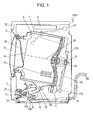
- Fig. 1 illustrates drum type washing machine 1001 according to an exemplary embodiment of the present invention.
- Washing machine 1001 includes rotatable drum 5, water tub 1 accommodating therein rotatable drum 5 to allow drum 5 rotatable about center axis 5A, housing 2 accommodating rotatable drum 5 and water tub 1, and door 8 provided at a front of housing 2.
- Rotatable drum 5 has loading port 25 which has a circular shape and is provided at the front side.
- Rotatable drum 5 is adapted to store a laundry, such as clothes, put into rotatable drum 5 from door 8 through loading port 25.
- Rotatable drum 5 has a bottom and a cylindrical side wall, and has opening 14 provided opposite to the bottom. Rotatable drum 5 is arranged so that opening 14 faces the front of housing 2, and the bottom faces the back of housing 2. Rotation shaft 15 extends from the bottom of rotatable drum 5 along center axis 5A. Rotation shaft 15 is rotatably supported by bearing 16 provided at the back of water tub 1.
- Motor 4 is mounted below water tub 1.
- Belt 19 connects between driving pulley 17A attached to a rotation driving axis of motor 4 and slave pulley 17B attached to rotation shaft 15.
- Motor 4 drives rotatable drum 5 via driving belt 19 between driving pulley 17A and slave pulley 17B so as to rotate drum 5.
- Water supplier 21 provided at the upper part of an inside of housing 2 supplies washing water into water tub 1.
- the washing water flows between the inside of rotatable drum 5 and the inside of water tub 1 via a lot of through-holes 20 provided in the side wall of rotatable drum 5.
- Rotatable drum 5 rotates to move the laundry containing the washing water upward and to then drops the laundry from the upper side, thereby beat-washing the laundry.
- Drain opening 1A through which the washing water is discharged from the water tub is provided at the lower part of water tub 1.
- Drain valve 10 is provided at the lower part of water tub 1 and at drain opening 1A. Drain valve 10 allows the water to be discharged and stops the discharging of the water from water tub 1 through drain opening 1A.
- Drain pump 11 discharges the water forcibly from water tub 1.
- Filter unit 12 is provided in the middle of drain passage 10A connecting drain valve 10 to suction port 11A of drain pump 11.
- Discharge opening 11B of drain pump 11 is connected to drain hose 6 for discharging the washing water to an outside of washing machine 1001. If a place to which the washing water is discharged is higher than a floor on which washing machine 1001 is installed, tip 6A of drain hose 6 may be located above drain opening 1A. Even in this case, drain pump 11 discharges the washing water forcibly from water tub 1 to the outside of washing machine 1001. In the case that the washing water is discharged through tip 6A of drain hose 6 to a place, such as a drain ditch, below the floor, drain pump 11 discharges the washing water for a short time.
- Cap 31 for operating filter unit 12 is provided in space 7 provided at the lower part of front of housing 2.
- Filter unit 12 removes particles, such as lint, suspended in the discharged washing water.
- the washing water having the particles removed by filter unit 12 is sent to drain pump 11, hence preventing the clogging of drain pump 11 and the clogging of a drainage water pipe line at the exterior of washing machine 1001.
- Controller 3 implemented by, for example, a microcomputer, installed in the upper part of housing 2 controls a series of processes, such as a washing process, a rinsing process, and a spin-drying process, and controls motor 4, drain valve 10, and drain pump 11.
- An input panel and indicator 22 are provided on the front surface of the upper part of housing 2.
- the input panel includes a start switch. The start switch starts the operation of washing machine 1001.
- the indicator 22 displays, for example, a washing sequence to be executed and a remaining time.
- drain valve 10 is closed, and washing water does not fill hose 13. Thus, even if cap 31 is operated to remove the filter, the washing water does not leak from filter unit 12.
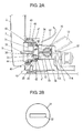
- Fig. 2A is an enlarged cross-sectional view of drum type washing machine 1001 for illustrating filter unit 12.
- Fig. 2B is a front view of cap 31.
- cap 31 is accommodated in space 7 of housing 2 and does not protrude from outer contour 9 of housing 2.
- cap 31 has a circular shape as seen from the front, and has tab 32 extending linearly. A user facing the front surface of housing 2 can pinch tab 32 with fingers to rotate cap 31.
- Filter unit 12 includes filter case 39 having cap 31 detachably attached thereto and filter 34 stored in filter case 39.
- Filter case 39 has inflow opening 36 connected to hose 13 and outflow opening 37 connected to suction port 11A of drain pump 11.
- Filter case 39 has installation opening 35 having cylindrical wall 42 adapted to have cap 31 fixed thereto.
- Sealing ring 40 made of elastic material, such as rubber, is attached to an outer circumference of installation opening 35. Sealing ring 40 contacts front surface 41 of filter case 39 to seal cap 31 and filter case 39.
- Cap 31 has engaging protrusion 38 extending to the interior of housing 2. Engaging protrusion 38 is engaged with engaging recess 33 formed in filter 34. Upon rotating tab 32, the user can rotate cap 31 to remove cap 31 from installation opening 35 of filter case 39. Then, the user can hold tab 32 with fingers to pull out cap 31, thereby taking filter 34 out of filter case 39.
- washing water containing the particles such as lint
- filter 34 When the washing water containing the particles, such as lint, passes through filter 34 through inflow opening 36, the particles are caught by filter 34 and are removed from the washing water.
- the washing water having the particles removed therefrom is sent from outflow opening 37 to drain pump 11, and is discharged via drain hose 6 to the outside of washing machine 1001.
- Cylindrical wall 42 is formed unitarily with filter case 39 and protrudes toward space 7 in housing 2. Cylindrical wall 42 has a diameter larger than that of installation opening 35, and accommodates cap 31 rotatably. Protrusions 43 are provided on an inner circumference of cylindrical wall 42. Protrusion 45 is provided on outer circumference 44 of cap 31. Upon the user pushing cap 31 to filter 34 to push sealing ring 40 to front surface 41 of filter case 39, sealing ring 40 contacts front surface 41 of filter case 39 securely, thereby preventing the washing water stored in filter case 39 from leaking from cap 31.
- Magnetic body 46 is located at a portion of outer circumference 44 of cap 31.
- Mounting plate 47 is provided unitarily on filter case 39 above an outer circumference of cylindrical wall 42.
- Reed switch 48 is mounted to mounting plate 47.
- Reed switch 48 includes magnetic actuator 49 activated by magnetic field.
- Reed switch 48 is arranged to allow magnetic actuator 49 to be located close to magnetic body 46.
- cap 31 when cap 31 is positioned at a predetermined position, cap 31 causes sealing ring 40 to contact filter case 39 securely to seal cap 31 and filter case 39.
- magnetic body 46 is located close to magnetic actuator 49 and turns on magnetic actuator 49 to activate reed switch 48, thereby causing reed switch 48 to send an activation signal via signal line 52 to controller 3.
- cap 31 and filter case 39 are not sealed completely. In this case, magnetic body 46 is located away from magnetic actuator 49 to turn off magnetic actuator 49 to deactivate reed switch 48, thereby allowing seed switch 48 to send a deactivation signal via signal line 52 to controller 3.
- Controller 3 determines whether reed switch 48 outputs the activation signal or the deactivation signal. In the case that reed switch 48 which is deactivated does not actually output any signal, controller 3 can determine that reed switch 48 does not output any signal. Thus, even in this case, it is assumed that reed switch 48 effectively outputs the deactivation signal when reed switch 48 is deactivated.
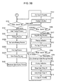
- FIGs. 3A and 3B are flowcharts illustrating the operation of drum type washing machine 1001.
- Step S100 the user opens door 8 to put a laundry, such as clothes, and detergent into rotatable drum 5 of drum type washing machine 1001 and turn on a power switch. Then, the user sets a desired operation washing sequence (Step S101), and then, turns on the start switch (Step S102). At Step S102, controller 3 closes drain valve 10 and deactivate motor 4, drain pump 11, and water supplier 21.
- controller 3 determines whether reed switch 48 outputs the activation signal or the deactivation signal (Step S103).
- controller 3 If determining at Step S103 that reed switch 48 outputs the activation signal, controller 3 starts a washing process for washing the laundry by activating water supplier 21 to supply water to rotatable drum 5 and driving motor 4 (Step S104).
- controller 3 displays a predetermined indication on indicator 22 (Step S111). This indication indicates that cap 31 is not positioned at the predetermined position, and notifies the user of a recoverable abnormality as a message such as "the filter unit must be retightened".
- indicator 22 may generate a warning sound.
- controller 3 determines at Step S103 whether reed switch 48 outputs the activation signal or the deactivation signal. Then, controller 3 repeats the operations of Steps S103 and S111.
- Step S103 While the operations of Steps S103 and S111 are repeated, the user recognizes the indication displayed on indicator 22 at Step S111, and fix cap 31 to the predetermined position (Step S112).
- controller 3 determines at Step S103 that reed switch 48 outputs the activation signal, and than starts the washing process at Step S104.
- controller 3 executes the washing process (Step S105). While executing the washing process at Step S105, controller 3 determines whether reed switch 48 outputs the activation signal or the deactivation signal (Step S106). While determining at Step S106 that reed switch 48 outputs the activation signal, controller 3 executes the washing process at Step S105. When terminating the washing process (Step S105A), controller 3 deactivates water supplier 21 and stops driving motor 4.
- controller 3 When determining at Step S106 that reed switch 48 outputs the deactivation signal, controller 3 immediately stops the washing process (S210) and displays the above indication on indicator 22 (Step S211). At Step S211, indicator 22 may generate a warning sound.
- controller 3 determines at Step S106 whether reed switch 48 outputs the activation signal or the deactivation signal, and repeats the operations of Steps S106 and S211. While the operations of Steps S106 and S211 are repeated, the user recognizes the indication displayed on indicator 22 at Step S211 and fixes cap 31 at the predetermined position (Step S212).
- controller 3 determines at Step S106 that reed switch 48 outputs the activation signal, and then, executes the washing process from the stage of the washing process stopped at Step S210. Thus, even if the user opens cap 31 of filter unit 12, the user prevents a washing time from extending by closing cap 31 again.
- drain valve 10 is closed and prevents the washing water from filling filter unit 12 and drain pump 11. Hence, even if cap 31 is opened, the washing water does not leak from filter unit 12.
- controller 3 executes a draining process to open drain valve 10 and drive drain pump 11 so as to discharge the washing water stored in rotatable drum 5 and water tub 1 through drain opening 1A (Step S107A). While executing the draining process at Step S107A, controller 3 determines whether reed switch 48 outputs the activation signal or the deactivation signal (Step S108). While determining at Step S108 that reed switch 48 outputs the activation signal, controller 3 executes the draining process at Step S107A. When the draining process is terminated (Step S109), controller 3 closes drain valve 10.
- controller 3 When determining at Step S108 that reed switch 48 outputs the deactivation signal, controller 3 immediately stops the draining process (Step S114) and displays the above indication on indicator 22 (Step S115). At Step S115, indicator 22 may generate a warning sound. Simultaneously to the displaying of the indication, controller 3 closes drain valve 10 (Step S116), and drives drain pump 11 (Step S117) to discharge washing water remaining in hose 13 and filter unit 12 through drain hose 6. After displaying the indication at Step S115 and discharging the washing water at Step S117, controller 3 determines at Step S108 whether reed switch 48 outputs the activation signal or the deactivation signal, and than, repeats the operations of Steps S108 and S115.
- Step S118 the user recognizes the indication displayed on indicator 22 at Step S211 and fixes cap 31 at the predetermined position.
- controller 3 determines at Step S108 that reed switch 48 outputs the activation signal, and then, opens drain valve 10 and restarts the draining process from the stage of the draining process stopped at Step 105. Then, the draining process is terminated at Step S109.
- the user even if the user opens cap 31 of filter unit 12, the user prevents a washing time from extending by closing cap 31 again.
- controller 3 closes drain valve 10 and does not activate motor 4, drain pump 11, and water supplier 21.
- controller 3 determines whether reed switch 48 outputs the activation signal or the deactivation signal, as shown in Fig. 3B (Step S303).
- controller 3 activates water supplier 21 to supply water to rotatable drum 5 and drives motor 4 to start a rinsing process so as to rinse the laundry (Step S304).
- controller 3 When determining at Step S303 that reed switch 48 outputs the deactivation signal, controller 3 displays the predetermined indication on indicator 22 (Step S311). This indication indicates that cap 31 is not positioned at the predetermined position, and notifies the user of a recoverable abnormality as a message such as "the filter unit must be retightened". At Step S111, indicator 22 may generate a warning sound. After displaying the indication at Step S311, controller 3 determines at Step S303 whether reed switch 48 outputs the activation signal or the deactivation signal, and repeats the operations of Steps S303 and S311.
- Step S311 While the operations of Steps S303 and S311 are repeated, the user recognizes the indication displayed on indicator 22 at Step S311 and fixes cap 31 at the predetermined position (Step S312). After the user fixes cap 31 at the predetermined position at Step S312, controller 3 determines at Step S303 that reed switch 48 outputs the activation signal, and controller 3 starts the rinsing process at Step S104.
- Step S305 the controller 3 executes the rinsing process. While executing the rinsing process at Step S305, controller 3 determines whether reed switch 48 outputs the activation signal or the deactivation signal (Step S306). While determining at Step S306 that reed switch 48 outputs the activation signal, controller 3 executes the rinsing process at Step S305. When the rinsing process is terminated (Step S105A), controller 3 stops driving water supplier 21 and motor 4.
- controller 3 When determining at Step S306 that reed switch 48 outputs the deactivation signal, controller 3 immediately stops the rinsing process (Step S410) and displays the above indication on indicator 22 (Step S411). At Step S411, indicator 22 may generate a warning sound.
- controller 3 determines at Step S306 whether reed switch 48 outputs the activation signal or the deactivation signal, and repeats the operations of Steps S306 and S411. While the operations of Steps S306 and S411 are repeated, the user recognizes the indication displayed on indicator 22 at Step S411 and fixes cap 31 at the predetermined position (Step S412).
- controller 3 determines at Step S306 that reed switch 48 outputs the activation signal, and restarts the rinsing process from the stage of the rinsing process stopped at Step S305.
- drain valve 10 Since drain valve 10 is closed during the rinsing process, no water fills filter unit 12 and drain pump 11. Hence, even when cap 31 is opened, water does not leak from filter unit 12.
- controller 3 executes a draining process to open drain valve 10 and drive drain pump 11 so as to discharge the water stored in rotatable drum 5 and water tub 1 from drain opening 1A (Step S307A).
- controller 3 drives motor 4 to rotate rotatable drum 5 at a high rotation speed to execute a spin-drying process (Step S307B).
- Step S307B While executing the draining process and the spin-drying process being at Steps S307A and S307B, controller 3 determines whether reed switch 48 outputs the activation signal or the deactivation signal (Step S308).
- controller 3 While determining at Step S308 that reed switch 48 outputs the activation signal, controller 3 executes the draining process and the spin-drying process at Steps S307A and S307B. When the spin-drying process is terminated (Step S309), controller 3 stops driving motor 4.
- controller 3 When determining at Step S308 that reed switch 48 outputs the deactivation signal, controller 3 immediately stops a process out of the draining process and the spin-drying process that is executed (Step S314), and displays the above indication on indicator 22 (Step S315). At Step S315, indicator 22 may generate a warning sound. Simultaneously to the displaying of the indication, controller 3 closes drain valve 10 (Step S116), and drives drain pump 11 (Step S317) to discharge water remaining in hose 13 and filter unit 12 from drain hose 6.
- controller 3 determines at Step S308 whether reed switch 48 outputs the activation signal or the deactivation signal, and controller 3 repeats the operations of Steps S308 and S315. While the operations of Steps S308 and S315 are repeated, the user recognizes the indication displayed on indicator 22 at Step S411 and fixes cap 31 at the predetermined position (Step S318). After the user fixes cap 31 at the predetermined position at Step S318, controller 3 determines at Step S308 that reed switch 48 outputs the activation signal. The, controller 3 opens drain valve 10 and restart the process from the stage of the process stopped at Step S314. Then, the spin-drying process is terminated at Step S309. Thus, even if the user opens cap 31 of filter unit 12, the user prevents a washing time from extending by closing cap 31. again.
- washing machine 1001 prevents the washing water from leaking to the outside and allows the particles to be removed from filter 34 even when the inside and the outside of filter unit 12 communicate with each other. Thus, drum type washing machine 1001 can safely wash the laundry while preventing water from leaking.
Landscapes
- Engineering & Computer Science (AREA)
- Textile Engineering (AREA)
- Detail Structures Of Washing Machines And Dryers (AREA)
- Control Of Washing Machine And Dryer (AREA)
- Main Body Construction Of Washing Machines And Laundry Dryers (AREA)
Applications Claiming Priority (1)
| Application Number | Priority Date | Filing Date | Title |
|---|---|---|---|
| JP2008200783A JP4737245B2 (ja) | 2008-08-04 | 2008-08-04 | ドラム式洗濯機 |
Publications (3)
| Publication Number | Publication Date |
|---|---|
| EP2151518A2 true EP2151518A2 (de) | 2010-02-10 |
| EP2151518A3 EP2151518A3 (de) | 2013-10-16 |
| EP2151518B1 EP2151518B1 (de) | 2014-09-10 |
Family
ID=41162737
Family Applications (1)
| Application Number | Title | Priority Date | Filing Date |
|---|---|---|---|
| EP09158891.3A Not-in-force EP2151518B1 (de) | 2008-08-04 | 2009-04-28 | Trommelwaschmaschine |
Country Status (4)
| Country | Link |
|---|---|
| EP (1) | EP2151518B1 (de) |
| JP (1) | JP4737245B2 (de) |
| CN (1) | CN101643991B (de) |
| RU (1) | RU2407834C1 (de) |
Cited By (5)
| Publication number | Priority date | Publication date | Assignee | Title |
|---|---|---|---|---|
| ES2462873R1 (es) * | 2012-11-26 | 2014-07-01 | Bsh Electrodom�Sticos Espa�A S.A. | Dispositivos de vaciado de líquido de lavado para máquina lavadora, máquina lavadora y bomba de desagüe |
| US20220008845A1 (en) * | 2018-10-31 | 2022-01-13 | Ufi Innovation Center S.R.L. | Washing machine with filter group |
| US20230416971A1 (en) * | 2022-06-28 | 2023-12-28 | Samsung Electronics Co., Ltd. | Washing machine and controlling method of washing machine |
| EP3988698B1 (de) | 2020-10-23 | 2024-07-10 | Miele & Cie. KG | Waschmaschine |
| WO2025109309A1 (en) * | 2023-11-22 | 2025-05-30 | Xeros Limited | A filter unit and filtration method |
Families Citing this family (6)
| Publication number | Priority date | Publication date | Assignee | Title |
|---|---|---|---|---|
| JP5656817B2 (ja) * | 2011-12-26 | 2015-01-21 | 日立アプライアンス株式会社 | 洗濯機 |
| KR101933139B1 (ko) * | 2012-01-10 | 2018-12-28 | 삼성전자주식회사 | 드럼 세탁기 |
| JP2016158744A (ja) * | 2015-02-27 | 2016-09-05 | パナソニックIpマネジメント株式会社 | 洗濯機 |
| CN107237090B (zh) * | 2016-03-28 | 2021-03-26 | 青岛海尔洗涤电器有限公司 | 一种排水过滤器及采用其的洗衣机 |
| DE102016212481A1 (de) * | 2016-07-08 | 2018-01-11 | BSH Hausgeräte GmbH | Haushaltsgerät mit einem Pumpenfilter |
| WO2024005369A1 (ko) * | 2022-06-28 | 2024-01-04 | 삼성전자주식회사 | 세탁기 및 세탁기의 제어방법 |
Citations (2)
| Publication number | Priority date | Publication date | Assignee | Title |
|---|---|---|---|---|
| JP2001104690A (ja) | 1999-10-07 | 2001-04-17 | Matsushita Electric Ind Co Ltd | ドラム式洗濯機 |
| JP2002282616A (ja) | 2001-03-27 | 2002-10-02 | Sharp Corp | フィルター装置 |
Family Cites Families (7)
| Publication number | Priority date | Publication date | Assignee | Title |
|---|---|---|---|---|
| SU1118729A1 (ru) * | 1982-05-06 | 1984-10-15 | Кишиневский Завод "Электромашина" | Клапанное устройство двухбаковой стиральной машины |
| JP2000084295A (ja) * | 1998-09-17 | 2000-03-28 | Rinnai Corp | 衣類乾燥機 |
| JP3727279B2 (ja) * | 2002-03-28 | 2005-12-14 | シャープ株式会社 | 洗濯機 |
| DE602005020440D1 (de) * | 2004-06-01 | 2010-05-20 | Lg Electronics Inc | Ablasssystem für trommelwaschmaschine |
| JP4494169B2 (ja) * | 2004-11-11 | 2010-06-30 | パナソニック株式会社 | ドラム式洗濯乾燥機 |
| JP2006271891A (ja) * | 2005-03-30 | 2006-10-12 | Sharp Corp | 洗濯機 |
| JP4667247B2 (ja) * | 2006-01-06 | 2011-04-06 | 三洋電機株式会社 | 洗濯機 |
-
2008
- 2008-08-04 JP JP2008200783A patent/JP4737245B2/ja not_active Expired - Fee Related
-
2009
- 2009-04-28 EP EP09158891.3A patent/EP2151518B1/de not_active Not-in-force
- 2009-06-29 RU RU2009124705/21A patent/RU2407834C1/ru not_active IP Right Cessation
- 2009-08-04 CN CN2009101590378A patent/CN101643991B/zh not_active Expired - Fee Related
Patent Citations (2)
| Publication number | Priority date | Publication date | Assignee | Title |
|---|---|---|---|---|
| JP2001104690A (ja) | 1999-10-07 | 2001-04-17 | Matsushita Electric Ind Co Ltd | ドラム式洗濯機 |
| JP2002282616A (ja) | 2001-03-27 | 2002-10-02 | Sharp Corp | フィルター装置 |
Cited By (6)
| Publication number | Priority date | Publication date | Assignee | Title |
|---|---|---|---|---|
| ES2462873R1 (es) * | 2012-11-26 | 2014-07-01 | Bsh Electrodom�Sticos Espa�A S.A. | Dispositivos de vaciado de líquido de lavado para máquina lavadora, máquina lavadora y bomba de desagüe |
| US20220008845A1 (en) * | 2018-10-31 | 2022-01-13 | Ufi Innovation Center S.R.L. | Washing machine with filter group |
| EP3988698B1 (de) | 2020-10-23 | 2024-07-10 | Miele & Cie. KG | Waschmaschine |
| US20230416971A1 (en) * | 2022-06-28 | 2023-12-28 | Samsung Electronics Co., Ltd. | Washing machine and controlling method of washing machine |
| US12584263B2 (en) * | 2022-06-28 | 2026-03-24 | Samsung Electronics Co., Ltd. | Washing machine and controlling method of washing machine |
| WO2025109309A1 (en) * | 2023-11-22 | 2025-05-30 | Xeros Limited | A filter unit and filtration method |
Also Published As
| Publication number | Publication date |
|---|---|
| EP2151518B1 (de) | 2014-09-10 |
| EP2151518A3 (de) | 2013-10-16 |
| JP2010035748A (ja) | 2010-02-18 |
| CN101643991A (zh) | 2010-02-10 |
| RU2407834C1 (ru) | 2010-12-27 |
| CN101643991B (zh) | 2012-05-23 |
| JP4737245B2 (ja) | 2011-07-27 |
Similar Documents
| Publication | Publication Date | Title |
|---|---|---|
| EP2151518B1 (de) | Trommelwaschmaschine | |
| TWI641739B (zh) | washing machine | |
| EP1751343B1 (de) | Ablasssystem für trommelwaschmaschine | |
| US9169592B2 (en) | Washing machine and method of controlling the same | |
| EP4219821A1 (de) | Drainageflüssigkeitskanal mit filter und waschmaschine damit | |
| JP3686960B2 (ja) | フィルター装置、フィルター装置を備えた洗濯機 | |
| CN113226576A (zh) | 超声波清洗装置及洗衣机 | |
| CN113056581A (zh) | 超声波清洗装置及洗衣机 | |
| KR20020060930A (ko) | 드럼식 세탁기 | |
| EP2290148A1 (de) | Waschmaschine | |
| JP2005253990A (ja) | 洗濯機 | |
| KR20180136084A (ko) | 벽걸이형 세탁기 및 그의 리어 패널 | |
| KR20180136107A (ko) | 벽걸이형 세탁기 및 그의 도어 개스킷 | |
| WO2020088309A1 (zh) | 滚筒洗衣机 | |
| CN112011953A (zh) | 洗衣机 | |
| JPH11226291A (ja) | 洗濯機 | |
| JP2007307067A (ja) | 洗濯乾燥機 | |
| WO2024022338A1 (zh) | 滚筒洗衣机 | |
| CN115884836B (zh) | 洗衣机 | |
| KR20070025293A (ko) | 세탁기 및 그 배수에러 감지방법 | |
| JP2014004274A (ja) | ドラム式洗濯機 | |
| JPH09290091A (ja) | 洗濯機 | |
| JP2004275480A (ja) | 洗濯機 | |
| JP7795735B2 (ja) | 洗濯機 | |
| JP4053059B2 (ja) | フィルター装置 |
Legal Events
| Date | Code | Title | Description |
|---|---|---|---|
| PUAI | Public reference made under article 153(3) epc to a published international application that has entered the european phase |
Free format text: ORIGINAL CODE: 0009012 |
|
| AK | Designated contracting states |
Kind code of ref document: A2 Designated state(s): AT BE BG CH CY CZ DE DK EE ES FI FR GB GR HR HU IE IS IT LI LT LU LV MC MK MT NL NO PL PT RO SE SI SK TR |
|
| PUAL | Search report despatched |
Free format text: ORIGINAL CODE: 0009013 |
|
| AK | Designated contracting states |
Kind code of ref document: A3 Designated state(s): AT BE BG CH CY CZ DE DK EE ES FI FR GB GR HR HU IE IS IT LI LT LU LV MC MK MT NL NO PL PT RO SE SI SK TR |
|
| RIC1 | Information provided on ipc code assigned before grant |
Ipc: D06F 39/10 20060101AFI20130909BHEP Ipc: D06F 39/08 20060101ALI20130909BHEP |
|
| 17P | Request for examination filed |
Effective date: 20140213 |
|
| RBV | Designated contracting states (corrected) |
Designated state(s): AT BE BG CH CY CZ DE DK EE ES FI FR GB GR HR HU IE IS IT LI LT LU LV MC MK MT NL NO PL PT RO SE SI SK TR |
|
| GRAP | Despatch of communication of intention to grant a patent |
Free format text: ORIGINAL CODE: EPIDOSNIGR1 |
|
| RIC1 | Information provided on ipc code assigned before grant |
Ipc: D06F 39/08 20060101ALI20140314BHEP Ipc: D06F 39/10 20060101AFI20140314BHEP |
|
| INTG | Intention to grant announced |
Effective date: 20140415 |
|
| GRAS | Grant fee paid |
Free format text: ORIGINAL CODE: EPIDOSNIGR3 |
|
| GRAA | (expected) grant |
Free format text: ORIGINAL CODE: 0009210 |
|
| AK | Designated contracting states |
Kind code of ref document: B1 Designated state(s): AT BE BG CH CY CZ DE DK EE ES FI FR GB GR HR HU IE IS IT LI LT LU LV MC MK MT NL NO PL PT RO SE SI SK TR |
|
| REG | Reference to a national code |
Ref country code: GB Ref legal event code: FG4D |
|
| REG | Reference to a national code |
Ref country code: CH Ref legal event code: EP |
|
| REG | Reference to a national code |
Ref country code: IE Ref legal event code: FG4D |
|
| REG | Reference to a national code |
Ref country code: AT Ref legal event code: REF Ref document number: 686760 Country of ref document: AT Kind code of ref document: T Effective date: 20141015 |
|
| REG | Reference to a national code |
Ref country code: DE Ref legal event code: R096 Ref document number: 602009026543 Country of ref document: DE Effective date: 20141023 |
|
| PG25 | Lapsed in a contracting state [announced via postgrant information from national office to epo] |
Ref country code: SE Free format text: LAPSE BECAUSE OF FAILURE TO SUBMIT A TRANSLATION OF THE DESCRIPTION OR TO PAY THE FEE WITHIN THE PRESCRIBED TIME-LIMIT Effective date: 20140910 Ref country code: LT Free format text: LAPSE BECAUSE OF FAILURE TO SUBMIT A TRANSLATION OF THE DESCRIPTION OR TO PAY THE FEE WITHIN THE PRESCRIBED TIME-LIMIT Effective date: 20140910 Ref country code: NO Free format text: LAPSE BECAUSE OF FAILURE TO SUBMIT A TRANSLATION OF THE DESCRIPTION OR TO PAY THE FEE WITHIN THE PRESCRIBED TIME-LIMIT Effective date: 20141210 Ref country code: FI Free format text: LAPSE BECAUSE OF FAILURE TO SUBMIT A TRANSLATION OF THE DESCRIPTION OR TO PAY THE FEE WITHIN THE PRESCRIBED TIME-LIMIT Effective date: 20140910 Ref country code: ES Free format text: LAPSE BECAUSE OF FAILURE TO SUBMIT A TRANSLATION OF THE DESCRIPTION OR TO PAY THE FEE WITHIN THE PRESCRIBED TIME-LIMIT Effective date: 20140910 Ref country code: GR Free format text: LAPSE BECAUSE OF FAILURE TO SUBMIT A TRANSLATION OF THE DESCRIPTION OR TO PAY THE FEE WITHIN THE PRESCRIBED TIME-LIMIT Effective date: 20141211 |
|
| REG | Reference to a national code |
Ref country code: NL Ref legal event code: VDEP Effective date: 20140910 |
|
| REG | Reference to a national code |
Ref country code: LT Ref legal event code: MG4D |
|
| PG25 | Lapsed in a contracting state [announced via postgrant information from national office to epo] |
Ref country code: LV Free format text: LAPSE BECAUSE OF FAILURE TO SUBMIT A TRANSLATION OF THE DESCRIPTION OR TO PAY THE FEE WITHIN THE PRESCRIBED TIME-LIMIT Effective date: 20140910 Ref country code: CY Free format text: LAPSE BECAUSE OF FAILURE TO SUBMIT A TRANSLATION OF THE DESCRIPTION OR TO PAY THE FEE WITHIN THE PRESCRIBED TIME-LIMIT Effective date: 20140910 Ref country code: HR Free format text: LAPSE BECAUSE OF FAILURE TO SUBMIT A TRANSLATION OF THE DESCRIPTION OR TO PAY THE FEE WITHIN THE PRESCRIBED TIME-LIMIT Effective date: 20140910 |
|
| REG | Reference to a national code |
Ref country code: AT Ref legal event code: MK05 Ref document number: 686760 Country of ref document: AT Kind code of ref document: T Effective date: 20140910 |
|
| PG25 | Lapsed in a contracting state [announced via postgrant information from national office to epo] |
Ref country code: NL Free format text: LAPSE BECAUSE OF FAILURE TO SUBMIT A TRANSLATION OF THE DESCRIPTION OR TO PAY THE FEE WITHIN THE PRESCRIBED TIME-LIMIT Effective date: 20140910 |
|
| REG | Reference to a national code |
Ref country code: FR Ref legal event code: PLFP Year of fee payment: 7 |
|
| PG25 | Lapsed in a contracting state [announced via postgrant information from national office to epo] |
Ref country code: SK Free format text: LAPSE BECAUSE OF FAILURE TO SUBMIT A TRANSLATION OF THE DESCRIPTION OR TO PAY THE FEE WITHIN THE PRESCRIBED TIME-LIMIT Effective date: 20140910 Ref country code: EE Free format text: LAPSE BECAUSE OF FAILURE TO SUBMIT A TRANSLATION OF THE DESCRIPTION OR TO PAY THE FEE WITHIN THE PRESCRIBED TIME-LIMIT Effective date: 20140910 Ref country code: PT Free format text: LAPSE BECAUSE OF FAILURE TO SUBMIT A TRANSLATION OF THE DESCRIPTION OR TO PAY THE FEE WITHIN THE PRESCRIBED TIME-LIMIT Effective date: 20150112 Ref country code: IS Free format text: LAPSE BECAUSE OF FAILURE TO SUBMIT A TRANSLATION OF THE DESCRIPTION OR TO PAY THE FEE WITHIN THE PRESCRIBED TIME-LIMIT Effective date: 20150110 Ref country code: RO Free format text: LAPSE BECAUSE OF FAILURE TO SUBMIT A TRANSLATION OF THE DESCRIPTION OR TO PAY THE FEE WITHIN THE PRESCRIBED TIME-LIMIT Effective date: 20140910 Ref country code: CZ Free format text: LAPSE BECAUSE OF FAILURE TO SUBMIT A TRANSLATION OF THE DESCRIPTION OR TO PAY THE FEE WITHIN THE PRESCRIBED TIME-LIMIT Effective date: 20140910 |
|
| PG25 | Lapsed in a contracting state [announced via postgrant information from national office to epo] |
Ref country code: PL Free format text: LAPSE BECAUSE OF FAILURE TO SUBMIT A TRANSLATION OF THE DESCRIPTION OR TO PAY THE FEE WITHIN THE PRESCRIBED TIME-LIMIT Effective date: 20140910 Ref country code: AT Free format text: LAPSE BECAUSE OF FAILURE TO SUBMIT A TRANSLATION OF THE DESCRIPTION OR TO PAY THE FEE WITHIN THE PRESCRIBED TIME-LIMIT Effective date: 20140910 |
|
| REG | Reference to a national code |
Ref country code: DE Ref legal event code: R097 Ref document number: 602009026543 Country of ref document: DE |
|
| PLBE | No opposition filed within time limit |
Free format text: ORIGINAL CODE: 0009261 |
|
| STAA | Information on the status of an ep patent application or granted ep patent |
Free format text: STATUS: NO OPPOSITION FILED WITHIN TIME LIMIT |
|
| PG25 | Lapsed in a contracting state [announced via postgrant information from national office to epo] |
Ref country code: DK Free format text: LAPSE BECAUSE OF FAILURE TO SUBMIT A TRANSLATION OF THE DESCRIPTION OR TO PAY THE FEE WITHIN THE PRESCRIBED TIME-LIMIT Effective date: 20140910 |
|
| PGFP | Annual fee paid to national office [announced via postgrant information from national office to epo] |
Ref country code: GB Payment date: 20150420 Year of fee payment: 7 |
|
| 26N | No opposition filed |
Effective date: 20150611 |
|
| PG25 | Lapsed in a contracting state [announced via postgrant information from national office to epo] |
Ref country code: IT Free format text: LAPSE BECAUSE OF FAILURE TO SUBMIT A TRANSLATION OF THE DESCRIPTION OR TO PAY THE FEE WITHIN THE PRESCRIBED TIME-LIMIT Effective date: 20140910 |
|
| PGFP | Annual fee paid to national office [announced via postgrant information from national office to epo] |
Ref country code: FR Payment date: 20150421 Year of fee payment: 7 |
|
| PG25 | Lapsed in a contracting state [announced via postgrant information from national office to epo] |
Ref country code: MC Free format text: LAPSE BECAUSE OF FAILURE TO SUBMIT A TRANSLATION OF THE DESCRIPTION OR TO PAY THE FEE WITHIN THE PRESCRIBED TIME-LIMIT Effective date: 20140910 Ref country code: LU Free format text: LAPSE BECAUSE OF FAILURE TO SUBMIT A TRANSLATION OF THE DESCRIPTION OR TO PAY THE FEE WITHIN THE PRESCRIBED TIME-LIMIT Effective date: 20150428 Ref country code: SI Free format text: LAPSE BECAUSE OF FAILURE TO SUBMIT A TRANSLATION OF THE DESCRIPTION OR TO PAY THE FEE WITHIN THE PRESCRIBED TIME-LIMIT Effective date: 20140910 |
|
| REG | Reference to a national code |
Ref country code: CH Ref legal event code: PL |
|
| REG | Reference to a national code |
Ref country code: IE Ref legal event code: MM4A |
|
| PG25 | Lapsed in a contracting state [announced via postgrant information from national office to epo] |
Ref country code: CH Free format text: LAPSE BECAUSE OF NON-PAYMENT OF DUE FEES Effective date: 20150430 Ref country code: LI Free format text: LAPSE BECAUSE OF NON-PAYMENT OF DUE FEES Effective date: 20150430 |
|
| PG25 | Lapsed in a contracting state [announced via postgrant information from national office to epo] |
Ref country code: IE Free format text: LAPSE BECAUSE OF NON-PAYMENT OF DUE FEES Effective date: 20150428 |
|
| PG25 | Lapsed in a contracting state [announced via postgrant information from national office to epo] |
Ref country code: BE Free format text: LAPSE BECAUSE OF FAILURE TO SUBMIT A TRANSLATION OF THE DESCRIPTION OR TO PAY THE FEE WITHIN THE PRESCRIBED TIME-LIMIT Effective date: 20140910 |
|
| GBPC | Gb: european patent ceased through non-payment of renewal fee |
Effective date: 20160428 |
|
| PG25 | Lapsed in a contracting state [announced via postgrant information from national office to epo] |
Ref country code: MT Free format text: LAPSE BECAUSE OF FAILURE TO SUBMIT A TRANSLATION OF THE DESCRIPTION OR TO PAY THE FEE WITHIN THE PRESCRIBED TIME-LIMIT Effective date: 20140910 |
|
| REG | Reference to a national code |
Ref country code: FR Ref legal event code: ST Effective date: 20161230 |
|
| PG25 | Lapsed in a contracting state [announced via postgrant information from national office to epo] |
Ref country code: FR Free format text: LAPSE BECAUSE OF NON-PAYMENT OF DUE FEES Effective date: 20160502 Ref country code: GB Free format text: LAPSE BECAUSE OF NON-PAYMENT OF DUE FEES Effective date: 20160428 |
|
| PG25 | Lapsed in a contracting state [announced via postgrant information from national office to epo] |
Ref country code: BG Free format text: LAPSE BECAUSE OF FAILURE TO SUBMIT A TRANSLATION OF THE DESCRIPTION OR TO PAY THE FEE WITHIN THE PRESCRIBED TIME-LIMIT Effective date: 20140910 Ref country code: HU Free format text: LAPSE BECAUSE OF FAILURE TO SUBMIT A TRANSLATION OF THE DESCRIPTION OR TO PAY THE FEE WITHIN THE PRESCRIBED TIME-LIMIT; INVALID AB INITIO Effective date: 20090428 |
|
| PGFP | Annual fee paid to national office [announced via postgrant information from national office to epo] |
Ref country code: DE Payment date: 20170419 Year of fee payment: 9 |
|
| PG25 | Lapsed in a contracting state [announced via postgrant information from national office to epo] |
Ref country code: TR Free format text: LAPSE BECAUSE OF FAILURE TO SUBMIT A TRANSLATION OF THE DESCRIPTION OR TO PAY THE FEE WITHIN THE PRESCRIBED TIME-LIMIT Effective date: 20140910 |
|
| PG25 | Lapsed in a contracting state [announced via postgrant information from national office to epo] |
Ref country code: MK Free format text: LAPSE BECAUSE OF FAILURE TO SUBMIT A TRANSLATION OF THE DESCRIPTION OR TO PAY THE FEE WITHIN THE PRESCRIBED TIME-LIMIT Effective date: 20140910 |
|
| REG | Reference to a national code |
Ref country code: DE Ref legal event code: R119 Ref document number: 602009026543 Country of ref document: DE |
|
| PG25 | Lapsed in a contracting state [announced via postgrant information from national office to epo] |
Ref country code: DE Free format text: LAPSE BECAUSE OF NON-PAYMENT OF DUE FEES Effective date: 20181101 |