EP2149657A1 - Key for a lock cylinder and blank for such a key - Google Patents
Key for a lock cylinder and blank for such a key Download PDFInfo
- Publication number
- EP2149657A1 EP2149657A1 EP09164633A EP09164633A EP2149657A1 EP 2149657 A1 EP2149657 A1 EP 2149657A1 EP 09164633 A EP09164633 A EP 09164633A EP 09164633 A EP09164633 A EP 09164633A EP 2149657 A1 EP2149657 A1 EP 2149657A1
- Authority
- EP
- European Patent Office
- Prior art keywords
- key
- insertion path
- tip
- shaft
- inclination angle
- Prior art date
- Legal status (The legal status is an assumption and is not a legal conclusion. Google has not performed a legal analysis and makes no representation as to the accuracy of the status listed.)
- Granted
Links
- 238000003780 insertion Methods 0.000 claims abstract description 56
- 230000037431 insertion Effects 0.000 claims abstract description 56
- 210000000481 breast Anatomy 0.000 claims description 2
- 210000000038 chest Anatomy 0.000 claims description 2
- 230000000881 depressing effect Effects 0.000 claims description 2
- 238000004519 manufacturing process Methods 0.000 description 8
- 230000003068 static effect Effects 0.000 description 6
- 230000001133 acceleration Effects 0.000 description 1
- 238000000418 atomic force spectrum Methods 0.000 description 1
Images
Classifications
-
- E—FIXED CONSTRUCTIONS
- E05—LOCKS; KEYS; WINDOW OR DOOR FITTINGS; SAFES
- E05B—LOCKS; ACCESSORIES THEREFOR; HANDCUFFS
- E05B19/00—Keys; Accessories therefor
- E05B19/0017—Key profiles
- E05B19/0035—Key profiles characterized by longitudinal bit variations
-
- E—FIXED CONSTRUCTIONS
- E05—LOCKS; KEYS; WINDOW OR DOOR FITTINGS; SAFES
- E05B—LOCKS; ACCESSORIES THEREFOR; HANDCUFFS
- E05B17/00—Accessories in connection with locks
- E05B17/007—Devices for reducing friction between lock parts
-
- E—FIXED CONSTRUCTIONS
- E05—LOCKS; KEYS; WINDOW OR DOOR FITTINGS; SAFES
- E05B—LOCKS; ACCESSORIES THEREFOR; HANDCUFFS
- E05B19/00—Keys; Accessories therefor
- E05B19/0017—Key profiles
- E05B19/0041—Key profiles characterized by the cross-section of the key blade in a plane perpendicular to the longitudinal axis of the key
- E05B19/0052—Rectangular flat keys
Definitions
- Such keys are commonly used in today's locking systems and are for example from the DE 10 2004 009 166 A1 known.
- the insertion path of the key tip is arranged inclined to the next key notch. If the key is inserted into a closing channel of the lock cylinder, the insertion track slides over each of the pin tumblers and releases their static friction in the lock cylinder. The inclination of the insertion path thus has a great influence on the force required to insert the key in a lock channel.
- the insertion path of the key is formed as a continuous slope.
- the invention is based on the problem to form a key of the type mentioned so on that it has the largest possible number of locking variants and with the least possible effort in the lock cylinder is inserted. Furthermore, a blank for such a key is to be created, which allows easy production of the key with a large number of locking variants.
- the insertion path is inclined differently at its end facing the key tip and at its end closest to the key tip closest to the key slot relative to the longitudinal axis of the shaft.
- the small inclination angle ⁇ allows the solution of the static friction of the respective pin tumblers with little effort.
- the pin tumblers reach the large angle of inclination ⁇ , only a sliding friction that is low compared to static friction has to be overcome.
- the pin tumblers can be moved over a long distance with little effort and with a very short designed insertion path. This allows a large number of locking variants.
- Another advantage of this design is that the key without using the corresponding blank with a prepared insertion path after a copy only very difficult or not can be inserted into the lock cylinder.
- the key according to the invention has a particularly high copy protection.
- the small inclination angle ⁇ of the insertion path can be positioned according to another advantageous embodiment of the invention particularly close to the free ends of the pin tumblers of the lock cylinder when the key tip is designed dull and has a perpendicular to the longitudinal axis of the shaft edge.
- the portion of the insertion path having the small inclination angle ⁇ can be made particularly short, which contributes to a particularly short overall length of the key according to the invention.
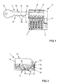
- the key 1 has a Reide 8 and a shaft 9 with a series of closing notches 10 for driving the Stiftzunnenen 7 of the lock cylinder 2.
- the closing notches 10 are arranged on a key-chest 11.
- One of the key-chest 11 remote key back 12 is straight.
- the key 1 has a key tip 13 with an insertion path 14.
- the insertion path 14 serves to depress the Stiftzuiensen 7 when inserting the key 1 in the closing channel 6.
- the insertion path 14 is concave curved.
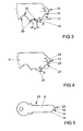
- FIG. 2 shows greatly enlarged the key tip 13 FIG. 1
- the concavely concave insertion path 14 at its the free end of the key tip 13 near section 15 a to the longitudinal axis of the shaft 9 small inclination angle ⁇ and at its the next closing notch facing portion 16 a to the longitudinal axis of the shaft 9 has large inclination angle ⁇ .
- the large inclination angle ⁇ having portion 16 of the insertion path 14 is up to the lowest possible Level of the closing notches 10 out. This are available for the possible closing variants of the key 1 in the key tip 13 closest to the closing notch 10 all levels available. The distance Y of the key tip 13 from the next closing notch 10 is thereby made particularly short.
- FIG. 5 shows a blank 25 for the production of the key 1 from FIG. 1 , It can be seen that a tip 26 of the blank 25, the in FIG. 2 having described shape with the insertion path 14. This blank 25 is intended to be provided with the described closing notches 20 and additional closing notches 26, without requiring reworking of the tip 26.
Abstract
Description
Die Erfindung betrifft einen Schlüssel für einen Schließzylinder mit einem Schaft, mit einer Reide, mit einer auf dem Schaft angeordneten Schlüsselbrust und einem der Schlüsselbrust abgewandten Schlüsselrücken, mit einer auf der Schlüsselbrust angeordneten, zum Niederdrücken von Stiftzuhaltungen im Schließzylinder vorgesehenen Reihe von Schließkerben, mit einer an dem der Reide abgewandten Ende des Schaftes angeordneten Schlüsselspitze und mit einer an der Schlüsselspitze auf der Seite der Schlüsselbrust angeordneten, bis zu der der Schlüsselspitze am nächsten angeordneten Schließkerbe geführten Einführbahn. Weiterhin betrifft die Erfindung einen Rohling für einen solchen Schlüssel, bei dem die Schlüsselbrust und der Schlüsselrücken auf dem Schaft parallel verlaufen.The invention relates to a key for a lock cylinder with a shaft, with a Reide, with a shaft arranged on the shaft and the keychain facing away from the back of the key, arranged on the key chest, provided for depressing pin tumblers in the lock cylinder series of locking notches, with a arranged at the end remote from the Reide end of the shaft arranged key tip and with a arranged on the key tip on the side of the key-chest, up to the key tip of the closest arranged notch guided insertion. Furthermore, the invention relates to a blank for such a key, in which the key-chest and the key back run parallel on the shaft.
Solche Schlüssel werden bei heutigen Schließsystemen häufig eingesetzt und sind beispielsweise aus der
Ein großer Neigungswinkel der Einführbahn zur Längsachse des Schaftes führt zu einem großen Widerstand beim Einführen des Schlüssels in den Schließzylinder. Ein kleiner Neigungswinkel der Einführbahn zur Längsachse des Schaftes führt jedoch dazu, dass die der Schlüsselspitze nächste Schließkerbe besonders tief angeordnet oder die Einführbahn besonders lang gestaltet sein muss. Die Vorgabe einer besonders tiefen Schließkerbe führt jedoch zu einer geringen Anzahl an möglichen Schließvarianten des Schlüssels. Ein besonders langer Schlüssel erfordert entsprechend lang gestaltete Schließzylinder mit wenigen Stiftzuhaltungen, was bei heutigen Schließsystemen häufig vermieden werden soll.A large angle of inclination of the insertion path to the longitudinal axis of the shaft leads to a large resistance during insertion of the key into the lock cylinder. However, a small angle of inclination of the insertion path to the longitudinal axis of the shaft leads to the fact that the key tip next key close arranged particularly deep or the insertion path must be designed to be particularly long. The specification of a particularly deep locking notch, however, leads to a small number of possible closing variants of the key. A particularly long key requires appropriately designed lock cylinder with a few pin tumblers, which is to be avoided in today's locking systems frequently.
Meist werden Rohlinge zur Fertigung eines solchen Schlüssels derart bereitgestellt, dass sie mit den Schließkerben versehen werden können. Diese Rohlinge weisen einen vorgegebenen Neigungswinkel der Einführbahn auf. Dieser Neigungswinkel wird bei der Herstellung des Schlüssels meist nicht verändert, so dass die Anzahl der Schließvarianten des Schlüssels begrenzt ist.Usually, blanks are provided for manufacturing such a key so that they can be provided with the locking notches. These blanks have a predetermined angle of inclination of the insertion path. This angle of inclination is usually not changed during the production of the key, so that the number of locking variants of the key is limited.
Der Erfindung liegt das Problem zugrunde, einen Schlüssel der eingangs genannten Art so weiter zu bilden, dass er eine möglichst große Anzahl an Schließvarianten aufweist und mit möglichst geringem Kraftaufwand in den Schließzylinder einführbar ist. Weiterhin soll ein Rohling für einen solchen Schlüssel geschaffen werden, welcher eine einfache Herstellung des Schlüssels mit einer großen Anzahl an Schließvarianten ermöglicht.The invention is based on the problem to form a key of the type mentioned so on that it has the largest possible number of locking variants and with the least possible effort in the lock cylinder is inserted. Furthermore, a blank for such a key is to be created, which allows easy production of the key with a large number of locking variants.
Das erstgenannte Problem wird erfindungsgemäß dadurch gelöst, dass ein Neigungswinkel α der Einführbahn zur Längsachse des Schaftes an der Schlüsselspitze kleiner ist als ein Neigungswinkel β der Einführbahn an der nächsten Schließkerbe.The first problem is inventively achieved in that an inclination angle α of the insertion path to the longitudinal axis of the shaft at the key tip is smaller than an inclination angle β of the insertion path at the next closing notch.
Durch diese Gestaltung ist die Einführbahn an ihrem der Schlüsselspitze zugewandten Ende und an ihrem der Schlüsselspitze am nächsten kommenden Schließkerbe zugewandten Ende zur Längsachse des Schaftes unterschiedlich geneigt. Hierdurch gelangt der kleine Neigungswinkel α beim Einführen des Schlüssels in den Schließkanal als erstes gegen die Stiftzuhaltungen. Der kleine Neigungswinkel α ermöglicht die Lösung der Haftreibung der jeweiligen Stiftzuhaltungen mit geringem Kraftaufwand. Wenn die Stiftzuhaltungen auf den großen Neigungswinkel β gelangen, muss nur noch eine im Vergleich zur Haftreibung geringe Gleitreibung überwunden werden. Damit können die Stiftzuhaltungen mit geringem Kraftaufwand und bei sehr kurz gestalteter Einführbahn über einen großen Weg bewegt werden. Dies ermöglicht eine große Anzahl an Schließvarianten. Ein weiterer Vorteil dieser Gestaltung besteht darin, dass der Schlüssel ohne Verwendung des entsprechenden Rohlings mit vorbereiteter Einführbahn nach einer Kopie nur sehr schwer oder nicht in den Schließzylinder eingeführt werden kann. Damit weist der erfindungsgemäße Schlüssel einen besonders hohen Kopierschutz auf.By virtue of this configuration, the insertion path is inclined differently at its end facing the key tip and at its end closest to the key tip closest to the key slot relative to the longitudinal axis of the shaft. As a result, the small inclination angle α when inserting the key into the closing channel first comes against the pin tumblers. The small inclination angle α allows the solution of the static friction of the respective pin tumblers with little effort. When the pin tumblers reach the large angle of inclination β, only a sliding friction that is low compared to static friction has to be overcome. Thus, the pin tumblers can be moved over a long distance with little effort and with a very short designed insertion path. This allows a large number of locking variants. Another advantage of this design is that the key without using the corresponding blank with a prepared insertion path after a copy only very difficult or not can be inserted into the lock cylinder. Thus, the key according to the invention has a particularly high copy protection.
Der erfindungsgemäße Schlüssel gestaltet sich konstruktiv besonders einfach und lässt sich kostengünstig fertigen, wenn die Einführbahn zwei Schrägen aufweist, wobei eine der Schrägen den Neigungswinkel α und die andere Schräge den Neigungswinkel β aufweist.The key according to the invention is structurally particularly simple and can be produced inexpensively if the insertion path has two slopes, one of the slopes having the inclination angle α and the other slope the inclination angle β.
Eine gleichmäßige Beschleunigung der Stiftzuhaltungen beim Einführen des Schlüssels in den Schließkanal lässt sich gemäß einer anderen vorteilhaften Weiterbildung der Erfindung einfach erzeugen, wenn die Einführbahn konkav gewölbt gestaltet ist. Durch diese Gestaltung wird ein besonders gleichmäßiges Ansteigen des Kraftverlaufs beim Einführen des erfindungsgemäßen Schlüssels in den Schließkanal sichergestellt. Ein unkomfortables Haken des Schlüssels wird dank der Erfindung vermieden. Hierbei können die Neigungswinkel α und β kontinuierlich ineinander übergehen. Diese Gestaltung trägt zur weiteren Erhöhung des Schutzes des erfindungsgemäßen Schlüssels gegen ein Kopieren bei, da die konkav gewölbte Gestaltung der Einführbahn nur sehr schwer ausgemessen werden kann. Gängige Kopiermaschinen sind zudem nicht für die gewölbte Fertigung der Einführbahn geeignet, was zur weiteren Erhöhung des Kopierschutzes beiträgt.A uniform acceleration of the pin tumblers when inserting the key in the lock channel can be easily generated according to another advantageous embodiment of the invention, when the insertion path is designed concave. By this design, a particularly uniform increase in the force curve during insertion of the key according to the invention in the Locking channel ensured. An uncomfortable hook of the key is avoided thanks to the invention. Here, the inclination angles α and β can continuously merge into each other. This design contributes to further increase the protection of the key according to the invention against copying, since the concave design of the insertion path can be very difficult to measure. Common copy machines are also not suitable for the curved production of the insertion path, which contributes to further increase the copy protection.
Zur weiteren Verringerung der Einführkräfte des Schlüssels in den Schließkanal trägt es gemäß einer anderen vorteilhaften Weiterbildung der Erfindung bei, wenn die Einführbahn eine Wellenform aufweist.To further reduce the insertion of the key in the closing channel, it contributes according to another advantageous embodiment of the invention, when the insertion path has a waveform.
Die möglichst genaue Positionierung des kleinen, zur Überwindung der Haftreibung vorgesehenen Neigungswinkels α gegenüber der Stiftzuhaltung des Schließzylinders ist bedeutsam für die Funktion des erfindungsgemäßen Schlüssels. Der kleine Neigungswinkel α der Einführbahn lässt sich gemäß einer anderen vorteilhaften Weiterbildung der Erfindung besonders nahe an den freien Enden der Stiftzuhaltungen des Schließzylinders positionieren, wenn die Schlüsselspitze stumpf gestaltet ist und eine senkrecht zur Längsachse des Schaftes angeordnete Kante hat. Durch diese Gestaltung kann der den kleinen Neigungswinkel α aufweisende Abschnitt der Einführbahn besonders kurz gestaltet sein, was zu einer besonders geringen Gesamtlänge des erfindungsgemäßen Schlüssels beiträgt.The most accurate positioning of the small, intended to overcome the static friction angle of inclination α relative to the pin tumbler of the lock cylinder is important for the function of the key according to the invention. The small inclination angle α of the insertion path can be positioned according to another advantageous embodiment of the invention particularly close to the free ends of the pin tumblers of the lock cylinder when the key tip is designed dull and has a perpendicular to the longitudinal axis of the shaft edge. As a result of this design, the portion of the insertion path having the small inclination angle α can be made particularly short, which contributes to a particularly short overall length of the key according to the invention.
Das zweitgenannte Problem, nämlich die Schaffung eines Rohlings für einen solchen Schlüssel, welcher eine einfache Herstellung des Schlüssels mit einer großen Anzahl an Schließvarianten ermöglicht, wird erfindungsgemäß dadurch gelöst, dass ein dem freien Ende des Schaftes naher Abschnitt einer Spitze des Schaftes einen flachen Neigungswinkel α zur Längsachse des Schaftes und ein von dem freien Ende der Spitze entfernter Abschnitt der Spitze des Schaftes einen großen Neigungswinkel β zur Längsachse des Schaftes aufweist.The second-mentioned problem, namely the creation of a blank for such a key, which enables a simple production of the key with a large number of locking variants, is achieved according to the invention in that a section close to the free end of the shank a tip of the shank has a shallow inclination angle α to the longitudinal axis of the shank and a portion of the tip of the shank remote from the free end of the tip has a large inclination angle β to the longitudinal axis of the shank.
Durch diese Gestaltung ist die Einführbahn des Schlüssels bereits auf dem Rohling angeordnet. Damit lässt sich der Schlüssel einfach durch Einarbeitung der Schließkerben fertigen. Der Rohling ermöglicht die besonders einfache Fertigung des Schlüssels mit einer großen Anzahl an Schließvarianten.By this design, the insertion path of the key is already arranged on the blank. Thus, the key can be easily finished by incorporating the locking notches. The blank enables the particularly simple production of the key with a large number of locking variants.
Die Erfindung lässt zahlreiche Ausführungsformen zu. Zur weiteren Verdeutlichung ihres Grundprinzips ist eine davon in der Zeichnung dargestellt und wird nachfolgend beschrieben. Diese zeigt in
- Fig. 1
- einen erfindungsgemäßen Schlüssel mit einem Schließzylinder,
- Fig. 2
- stark vergrößert eine Schlüsselspitze des Schlüssels aus
Figur 1 - Fig. 3
- eine weitere Ausführungsform der Schlüsselspitze mit einer zwei Schrägen aufweisenden Einführbahn,
- Fig. 4
- eine weitere Ausführungsform der Schlüsselspitze mit einer Wellenform an einer Einführbahn,
- Fig. 5
- einen Rohling zur Fertigung des Schlüssels aus
Figur 1
- Fig. 1
- a key according to the invention with a lock cylinder,
- Fig. 2
- greatly enlarges a key tip of the key
FIG. 1 with an arched entry track, - Fig. 3
- a further embodiment of the key tip with a two-slanted insertion path,
- Fig. 4
- another embodiment of the key tip with a wave form on an insertion path,
- Fig. 5
- a blank for the production of the key
FIG. 1 ,
Der Schlüssel 1 hat eine Reide 8 und einen Schaft 9 mit einer Reihe von Schließkerben 10 zur Ansteuerung der Stiftzuhaltungen 7 des Schließzylinders 2. Die Schließkerben 10 sind an einer Schlüsselbrust 11 angeordnet. Ein der Schlüsselbrust 11 abgewandter Schlüsselrücken 12 ist gerade gestaltet. An dem der Reide 8 abgewandten Ende des Schaftes 9 hat der Schlüssel 1 eine Schlüsselspitze 13 mit einer Einführbahn 14. Die Einführbahn 14 dient zum Niederdrücken der Stiftzuhaltungen 7 beim Einführen des Schlüssels 1 in den Schließkanal 6. Die Einführbahn 14 ist konkav gewölbt gestaltet.The
Weiterhin sind in
Wie in den Figuren auch dargestellt ist es sinnvoll, die Schlüsselspitze 13 mit zwei der erfinderischen Einführbahnen 14, 16, 17, 21 auszustatten, nämlich eine zur Schlüsselbrust 11 und eine zum Schlüsselrücken 12 hin. Dabei können die beiden Einführbahnen 14, 16, 17, 21 unterschiedlich lang, aber ggf. über die gemeinsame Länge spiegelsymmetrisch ausgebildet sein.As also shown in the figures, it makes sense to equip the
Claims (7)
Priority Applications (2)
| Application Number | Priority Date | Filing Date | Title |
|---|---|---|---|
| SI200930608T SI2149657T1 (en) | 2008-07-29 | 2009-07-06 | Key for a lock cylinder and blank for such a key |
| PL09164633T PL2149657T3 (en) | 2008-07-29 | 2009-07-06 | Key for a lock cylinder and blank for such a key |
Applications Claiming Priority (1)
| Application Number | Priority Date | Filing Date | Title |
|---|---|---|---|
| DE102008040823A DE102008040823A1 (en) | 2008-07-29 | 2008-07-29 | Key for a lock cylinder and blank for such a key |
Publications (2)
| Publication Number | Publication Date |
|---|---|
| EP2149657A1 true EP2149657A1 (en) | 2010-02-03 |
| EP2149657B1 EP2149657B1 (en) | 2013-03-27 |
Family
ID=41323431
Family Applications (1)
| Application Number | Title | Priority Date | Filing Date |
|---|---|---|---|
| EP09164633A Active EP2149657B1 (en) | 2008-07-29 | 2009-07-06 | Key for a lock cylinder and blank for such a key |
Country Status (6)
| Country | Link |
|---|---|
| EP (1) | EP2149657B1 (en) |
| DE (1) | DE102008040823A1 (en) |
| ES (1) | ES2407636T3 (en) |
| HR (1) | HRP20130492T1 (en) |
| PL (1) | PL2149657T3 (en) |
| SI (1) | SI2149657T1 (en) |
Cited By (1)
| Publication number | Priority date | Publication date | Assignee | Title |
|---|---|---|---|---|
| JP2016079702A (en) * | 2014-10-17 | 2016-05-16 | 河村電器産業株式会社 | Key for cabinet handle lock, and key for cylinder lock |
Citations (4)
| Publication number | Priority date | Publication date | Assignee | Title |
|---|---|---|---|---|
| US1977189A (en) * | 1933-12-04 | 1934-10-16 | Ivar G Larson | Lock |
| EP0942126A1 (en) * | 1998-02-28 | 1999-09-15 | Schliessanlagen GmbH Pfaffenhain | Locking device |
| EP1577469A2 (en) | 2004-03-19 | 2005-09-21 | Aug. Winkhaus GmbH & Co. KG | Key |
| DE102004009166A1 (en) | 2004-02-25 | 2005-10-06 | Aug. Winkhaus Gmbh & Co. Kg | Key for a lock cylinder comprises a recess having a free section in its center so that the contour of the free section deviates from boundary regions of the recess |
Family Cites Families (1)
| Publication number | Priority date | Publication date | Assignee | Title |
|---|---|---|---|---|
| AT506700B1 (en) * | 2008-07-15 | 2009-11-15 | Evva Werke | FLAT KEY |
-
2008
- 2008-07-29 DE DE102008040823A patent/DE102008040823A1/en not_active Withdrawn
-
2009
- 2009-07-06 PL PL09164633T patent/PL2149657T3/en unknown
- 2009-07-06 SI SI200930608T patent/SI2149657T1/en unknown
- 2009-07-06 EP EP09164633A patent/EP2149657B1/en active Active
- 2009-07-06 ES ES09164633T patent/ES2407636T3/en active Active
-
2013
- 2013-06-05 HR HRP20130492AT patent/HRP20130492T1/en unknown
Patent Citations (4)
| Publication number | Priority date | Publication date | Assignee | Title |
|---|---|---|---|---|
| US1977189A (en) * | 1933-12-04 | 1934-10-16 | Ivar G Larson | Lock |
| EP0942126A1 (en) * | 1998-02-28 | 1999-09-15 | Schliessanlagen GmbH Pfaffenhain | Locking device |
| DE102004009166A1 (en) | 2004-02-25 | 2005-10-06 | Aug. Winkhaus Gmbh & Co. Kg | Key for a lock cylinder comprises a recess having a free section in its center so that the contour of the free section deviates from boundary regions of the recess |
| EP1577469A2 (en) | 2004-03-19 | 2005-09-21 | Aug. Winkhaus GmbH & Co. KG | Key |
Cited By (1)
| Publication number | Priority date | Publication date | Assignee | Title |
|---|---|---|---|---|
| JP2016079702A (en) * | 2014-10-17 | 2016-05-16 | 河村電器産業株式会社 | Key for cabinet handle lock, and key for cylinder lock |
Also Published As
| Publication number | Publication date |
|---|---|
| SI2149657T1 (en) | 2013-07-31 |
| HRP20130492T1 (en) | 2013-06-30 |
| PL2149657T3 (en) | 2013-08-30 |
| EP2149657B1 (en) | 2013-03-27 |
| ES2407636T3 (en) | 2013-06-13 |
| DE102008040823A1 (en) | 2010-02-04 |
Similar Documents
| Publication | Publication Date | Title |
|---|---|---|
| EP2826937B1 (en) | Locking system | |
| AT411083B (en) | KEY FOR A PROFILE LOCKING CYLINDER AND PROFILE LOCKING CYLINDER | |
| EP2360334B1 (en) | Locking cylinder | |
| AT519857B1 (en) | Key and cylinder lock | |
| EP1806466A2 (en) | Cylinder lock with slide and flat key with guide rib | |
| DE3338713C2 (en) | Lock cylinder | |
| DE102010012261B4 (en) | locking system | |
| EP2149657B1 (en) | Key for a lock cylinder and blank for such a key | |
| DE102013103790A1 (en) | Coding via locking bar | |
| EP1577469B1 (en) | Key | |
| EP2765260B1 (en) | Locking cylinder | |
| EP1746226B1 (en) | Key | |
| EP2848755A2 (en) | Lock cylinder with a key authorised for locking | |
| EP2960405B1 (en) | Locking cylinder | |
| DE102007041964B3 (en) | Lock-key combination | |
| EP3266962B1 (en) | Key for a lock cylinder and lock cylinder for such a key | |
| DE2930425A1 (en) | CYLINDLE LOCK | |
| EP2078808B1 (en) | Key for a lock cylinder | |
| EP3696353A1 (en) | Locking device with a key and a locking cylinder | |
| EP2078807B1 (en) | Key for a lock cylinder | |
| DE102019128884A1 (en) | Lock cylinder | |
| EP3696352A1 (en) | Key for a locking cylinder | |
| DE102007056739A1 (en) | Cylinder lock, particularly for panel cylinder, has cylindrical housing and cylinder core that swivels in cylindrical housing and possesses key channel and multiple locking plates are arranged in cylinder core in adjustable manner | |
| EP3412849A1 (en) | Key for a lock cylinder and lock cylinder for such a key | |
| EP3112567A1 (en) | Device for activating or deactivating a day function in a lock |
Legal Events
| Date | Code | Title | Description |
|---|---|---|---|
| PUAI | Public reference made under article 153(3) epc to a published international application that has entered the european phase |
Free format text: ORIGINAL CODE: 0009012 |
|
| AK | Designated contracting states |
Kind code of ref document: A1 Designated state(s): AT BE BG CH CY CZ DE DK EE ES FI FR GB GR HR HU IE IS IT LI LT LU LV MC MK MT NL NO PL PT RO SE SI SK SM TR |
|
| AX | Request for extension of the european patent |
Extension state: AL BA RS |
|
| 17P | Request for examination filed |
Effective date: 20100217 |
|
| 17Q | First examination report despatched |
Effective date: 20110311 |
|
| GRAP | Despatch of communication of intention to grant a patent |
Free format text: ORIGINAL CODE: EPIDOSNIGR1 |
|
| GRAS | Grant fee paid |
Free format text: ORIGINAL CODE: EPIDOSNIGR3 |
|
| GRAA | (expected) grant |
Free format text: ORIGINAL CODE: 0009210 |
|
| AK | Designated contracting states |
Kind code of ref document: B1 Designated state(s): AT BE BG CH CY CZ DE DK EE ES FI FR GB GR HR HU IE IS IT LI LT LU LV MC MK MT NL NO PL PT RO SE SI SK SM TR |
|
| REG | Reference to a national code |
Ref country code: GB Ref legal event code: FG4D Free format text: NOT ENGLISH |
|
| REG | Reference to a national code |
Ref country code: CH Ref legal event code: EP |
|
| REG | Reference to a national code |
Ref country code: AT Ref legal event code: REF Ref document number: 603523 Country of ref document: AT Kind code of ref document: T Effective date: 20130415 |
|
| REG | Reference to a national code |
Ref country code: IE Ref legal event code: FG4D Free format text: LANGUAGE OF EP DOCUMENT: GERMAN |
|
| REG | Reference to a national code |
Ref country code: RO Ref legal event code: EPE |
|
| REG | Reference to a national code |
Ref country code: DE Ref legal event code: R096 Ref document number: 502009006627 Country of ref document: DE Effective date: 20130523 |
|
| REG | Reference to a national code |
Ref country code: CH Ref legal event code: NV Representative=s name: WAGNER PATENT AG, CH |
|
| REG | Reference to a national code |
Ref country code: HR Ref legal event code: TUEP Ref document number: P20130492 Country of ref document: HR |
|
| REG | Reference to a national code |
Ref country code: ES Ref legal event code: FG2A Ref document number: 2407636 Country of ref document: ES Kind code of ref document: T3 Effective date: 20130613 |
|
| REG | Reference to a national code |
Ref country code: HR Ref legal event code: T1PR Ref document number: P20130492 Country of ref document: HR |
|
| REG | Reference to a national code |
Ref country code: NL Ref legal event code: T3 |
|
| REG | Reference to a national code |
Ref country code: SE Ref legal event code: TRGR |
|
| PG25 | Lapsed in a contracting state [announced via postgrant information from national office to epo] |
Ref country code: LT Free format text: LAPSE BECAUSE OF FAILURE TO SUBMIT A TRANSLATION OF THE DESCRIPTION OR TO PAY THE FEE WITHIN THE PRESCRIBED TIME-LIMIT Effective date: 20130327 Ref country code: NO Free format text: LAPSE BECAUSE OF FAILURE TO SUBMIT A TRANSLATION OF THE DESCRIPTION OR TO PAY THE FEE WITHIN THE PRESCRIBED TIME-LIMIT Effective date: 20130627 |
|
| REG | Reference to a national code |
Ref country code: SK Ref legal event code: T3 Ref document number: E 14182 Country of ref document: SK |
|
| REG | Reference to a national code |
Ref country code: LT Ref legal event code: MG4D |
|
| PG25 | Lapsed in a contracting state [announced via postgrant information from national office to epo] |
Ref country code: GR Free format text: LAPSE BECAUSE OF FAILURE TO SUBMIT A TRANSLATION OF THE DESCRIPTION OR TO PAY THE FEE WITHIN THE PRESCRIBED TIME-LIMIT Effective date: 20130628 Ref country code: FI Free format text: LAPSE BECAUSE OF FAILURE TO SUBMIT A TRANSLATION OF THE DESCRIPTION OR TO PAY THE FEE WITHIN THE PRESCRIBED TIME-LIMIT Effective date: 20130327 Ref country code: LV Free format text: LAPSE BECAUSE OF FAILURE TO SUBMIT A TRANSLATION OF THE DESCRIPTION OR TO PAY THE FEE WITHIN THE PRESCRIBED TIME-LIMIT Effective date: 20130327 |
|
| REG | Reference to a national code |
Ref country code: PL Ref legal event code: T3 |
|
| PG25 | Lapsed in a contracting state [announced via postgrant information from national office to epo] |
Ref country code: PT Free format text: LAPSE BECAUSE OF FAILURE TO SUBMIT A TRANSLATION OF THE DESCRIPTION OR TO PAY THE FEE WITHIN THE PRESCRIBED TIME-LIMIT Effective date: 20130729 Ref country code: EE Free format text: LAPSE BECAUSE OF FAILURE TO SUBMIT A TRANSLATION OF THE DESCRIPTION OR TO PAY THE FEE WITHIN THE PRESCRIBED TIME-LIMIT Effective date: 20130327 Ref country code: IS Free format text: LAPSE BECAUSE OF FAILURE TO SUBMIT A TRANSLATION OF THE DESCRIPTION OR TO PAY THE FEE WITHIN THE PRESCRIBED TIME-LIMIT Effective date: 20130727 |
|
| PGFP | Annual fee paid to national office [announced via postgrant information from national office to epo] |
Ref country code: IE Payment date: 20130724 Year of fee payment: 5 |
|
| PG25 | Lapsed in a contracting state [announced via postgrant information from national office to epo] |
Ref country code: CY Free format text: LAPSE BECAUSE OF FAILURE TO SUBMIT A TRANSLATION OF THE DESCRIPTION OR TO PAY THE FEE WITHIN THE PRESCRIBED TIME-LIMIT Effective date: 20130327 |
|
| PG25 | Lapsed in a contracting state [announced via postgrant information from national office to epo] |
Ref country code: DK Free format text: LAPSE BECAUSE OF FAILURE TO SUBMIT A TRANSLATION OF THE DESCRIPTION OR TO PAY THE FEE WITHIN THE PRESCRIBED TIME-LIMIT Effective date: 20130327 |
|
| PLBE | No opposition filed within time limit |
Free format text: ORIGINAL CODE: 0009261 |
|
| STAA | Information on the status of an ep patent application or granted ep patent |
Free format text: STATUS: NO OPPOSITION FILED WITHIN TIME LIMIT |
|
| PG25 | Lapsed in a contracting state [announced via postgrant information from national office to epo] |
Ref country code: MC Free format text: LAPSE BECAUSE OF FAILURE TO SUBMIT A TRANSLATION OF THE DESCRIPTION OR TO PAY THE FEE WITHIN THE PRESCRIBED TIME-LIMIT Effective date: 20130327 |
|
| 26N | No opposition filed |
Effective date: 20140103 |
|
| REG | Reference to a national code |
Ref country code: CH Ref legal event code: PCAR Free format text: NEW ADDRESS: BAECHERSTRASSE 9, 8832 WOLLERAU (CH) |
|
| REG | Reference to a national code |
Ref country code: DE Ref legal event code: R097 Ref document number: 502009006627 Country of ref document: DE Effective date: 20140103 |
|
| REG | Reference to a national code |
Ref country code: IE Ref legal event code: MM4A |
|
| PG25 | Lapsed in a contracting state [announced via postgrant information from national office to epo] |
Ref country code: SM Free format text: LAPSE BECAUSE OF FAILURE TO SUBMIT A TRANSLATION OF THE DESCRIPTION OR TO PAY THE FEE WITHIN THE PRESCRIBED TIME-LIMIT Effective date: 20130327 |
|
| PG25 | Lapsed in a contracting state [announced via postgrant information from national office to epo] |
Ref country code: MT Free format text: LAPSE BECAUSE OF FAILURE TO SUBMIT A TRANSLATION OF THE DESCRIPTION OR TO PAY THE FEE WITHIN THE PRESCRIBED TIME-LIMIT Effective date: 20130327 |
|
| PG25 | Lapsed in a contracting state [announced via postgrant information from national office to epo] |
Ref country code: LU Free format text: LAPSE BECAUSE OF NON-PAYMENT OF DUE FEES Effective date: 20130706 Ref country code: HU Free format text: LAPSE BECAUSE OF FAILURE TO SUBMIT A TRANSLATION OF THE DESCRIPTION OR TO PAY THE FEE WITHIN THE PRESCRIBED TIME-LIMIT; INVALID AB INITIO Effective date: 20090706 |
|
| PGFP | Annual fee paid to national office [announced via postgrant information from national office to epo] |
Ref country code: TR Payment date: 20150616 Year of fee payment: 7 |
|
| PG25 | Lapsed in a contracting state [announced via postgrant information from national office to epo] |
Ref country code: IE Free format text: LAPSE BECAUSE OF NON-PAYMENT OF DUE FEES Effective date: 20140706 |
|
| PGFP | Annual fee paid to national office [announced via postgrant information from national office to epo] |
Ref country code: CH Payment date: 20150722 Year of fee payment: 7 |
|
| PGFP | Annual fee paid to national office [announced via postgrant information from national office to epo] |
Ref country code: SE Payment date: 20150731 Year of fee payment: 7 |
|
| REG | Reference to a national code |
Ref country code: FR Ref legal event code: PLFP Year of fee payment: 8 |
|
| REG | Reference to a national code |
Ref country code: CH Ref legal event code: PL |
|
| REG | Reference to a national code |
Ref country code: SE Ref legal event code: EUG |
|
| PG25 | Lapsed in a contracting state [announced via postgrant information from national office to epo] |
Ref country code: CH Free format text: LAPSE BECAUSE OF NON-PAYMENT OF DUE FEES Effective date: 20160731 Ref country code: SE Free format text: LAPSE BECAUSE OF NON-PAYMENT OF DUE FEES Effective date: 20160707 Ref country code: LI Free format text: LAPSE BECAUSE OF NON-PAYMENT OF DUE FEES Effective date: 20160731 |
|
| REG | Reference to a national code |
Ref country code: FR Ref legal event code: PLFP Year of fee payment: 9 |
|
| PGFP | Annual fee paid to national office [announced via postgrant information from national office to epo] |
Ref country code: MK Payment date: 20150610 Year of fee payment: 7 |
|
| REG | Reference to a national code |
Ref country code: FR Ref legal event code: PLFP Year of fee payment: 10 |
|
| PG25 | Lapsed in a contracting state [announced via postgrant information from national office to epo] |
Ref country code: MK Free format text: LAPSE BECAUSE OF NON-PAYMENT OF DUE FEES Effective date: 20160707 |
|
| REG | Reference to a national code |
Ref country code: HR Ref legal event code: ODRP Ref document number: P20130492 Country of ref document: HR Payment date: 20190627 Year of fee payment: 11 |
|
| REG | Reference to a national code |
Ref country code: HR Ref legal event code: ODRP Ref document number: P20130492 Country of ref document: HR Payment date: 20200617 Year of fee payment: 12 |
|
| REG | Reference to a national code |
Ref country code: HR Ref legal event code: ODRP Ref document number: P20130492 Country of ref document: HR Payment date: 20210624 Year of fee payment: 13 |
|
| PG25 | Lapsed in a contracting state [announced via postgrant information from national office to epo] |
Ref country code: TR Free format text: LAPSE BECAUSE OF NON-PAYMENT OF DUE FEES Effective date: 20160706 |
|
| REG | Reference to a national code |
Ref country code: HR Ref legal event code: ODRP Ref document number: P20130492 Country of ref document: HR Payment date: 20220628 Year of fee payment: 14 |
|
| PGFP | Annual fee paid to national office [announced via postgrant information from national office to epo] |
Ref country code: SK Payment date: 20220701 Year of fee payment: 14 Ref country code: GB Payment date: 20220725 Year of fee payment: 14 |
|
| PGFP | Annual fee paid to national office [announced via postgrant information from national office to epo] |
Ref country code: BE Payment date: 20220720 Year of fee payment: 14 |
|
| P01 | Opt-out of the competence of the unified patent court (upc) registered |
Effective date: 20230515 |
|
| REG | Reference to a national code |
Ref country code: HR Ref legal event code: ODRP Ref document number: P20130492 Country of ref document: HR Payment date: 20230628 Year of fee payment: 15 |
|
| PGFP | Annual fee paid to national office [announced via postgrant information from national office to epo] |
Ref country code: RO Payment date: 20230626 Year of fee payment: 15 Ref country code: CZ Payment date: 20230623 Year of fee payment: 15 |
|
| PGFP | Annual fee paid to national office [announced via postgrant information from national office to epo] |
Ref country code: PL Payment date: 20230623 Year of fee payment: 15 Ref country code: NL Payment date: 20230720 Year of fee payment: 15 Ref country code: HR Payment date: 20230628 Year of fee payment: 15 |
|
| PGFP | Annual fee paid to national office [announced via postgrant information from national office to epo] |
Ref country code: IT Payment date: 20230731 Year of fee payment: 15 Ref country code: ES Payment date: 20230821 Year of fee payment: 15 Ref country code: BG Payment date: 20230719 Year of fee payment: 15 Ref country code: AT Payment date: 20230718 Year of fee payment: 15 |
|
| PGFP | Annual fee paid to national office [announced via postgrant information from national office to epo] |
Ref country code: SI Payment date: 20230626 Year of fee payment: 15 Ref country code: FR Payment date: 20230724 Year of fee payment: 15 Ref country code: DE Payment date: 20230720 Year of fee payment: 15 |
|
| REG | Reference to a national code |
Ref country code: SK Ref legal event code: MM4A Ref document number: E 14182 Country of ref document: SK Effective date: 20230706 |
|
| GBPC | Gb: european patent ceased through non-payment of renewal fee |
Effective date: 20230706 |