EP1806466A2 - Cylinder lock with slide and flat key with guide rib - Google Patents
Cylinder lock with slide and flat key with guide rib Download PDFInfo
- Publication number
- EP1806466A2 EP1806466A2 EP07000151A EP07000151A EP1806466A2 EP 1806466 A2 EP1806466 A2 EP 1806466A2 EP 07000151 A EP07000151 A EP 07000151A EP 07000151 A EP07000151 A EP 07000151A EP 1806466 A2 EP1806466 A2 EP 1806466A2
- Authority
- EP
- European Patent Office
- Prior art keywords
- key
- control
- slide
- keyway
- recess
- Prior art date
- Legal status (The legal status is an assumption and is not a legal conclusion. Google has not performed a legal analysis and makes no representation as to the accuracy of the status listed.)
- Withdrawn
Links
- 238000003801 milling Methods 0.000 claims 1
- 238000004519 manufacturing process Methods 0.000 description 3
- 238000010276 construction Methods 0.000 description 2
- 230000002411 adverse Effects 0.000 description 1
- 230000000903 blocking effect Effects 0.000 description 1
Images

Classifications
-
- E—FIXED CONSTRUCTIONS
- E05—LOCKS; KEYS; WINDOW OR DOOR FITTINGS; SAFES
- E05B—LOCKS; ACCESSORIES THEREFOR; HANDCUFFS
- E05B27/00—Cylinder locks or other locks with tumbler pins or balls that are set by pushing the key in
- E05B27/0042—Cylinder locks or other locks with tumbler pins or balls that are set by pushing the key in with additional key identifying function, e.g. with use of additional key operated rotor-blocking elements, not of split pin tumbler type
-
- E—FIXED CONSTRUCTIONS
- E05—LOCKS; KEYS; WINDOW OR DOOR FITTINGS; SAFES
- E05B—LOCKS; ACCESSORIES THEREFOR; HANDCUFFS
- E05B19/00—Keys; Accessories therefor
- E05B19/0017—Key profiles
- E05B19/0041—Key profiles characterized by the cross-section of the key blade in a plane perpendicular to the longitudinal axis of the key
- E05B19/0052—Rectangular flat keys
-
- E—FIXED CONSTRUCTIONS
- E05—LOCKS; KEYS; WINDOW OR DOOR FITTINGS; SAFES
- E05B—LOCKS; ACCESSORIES THEREFOR; HANDCUFFS
- E05B31/00—Cylinder locks with both tumbler pins or balls and plate tumblers
Definitions
- the invention relates to a cylinder lock with rotatable cylinder core, which has a key channel for a flat key and sensing elements for cutting grooves and / or control surfaces of the key and locking elements that block the cylinder core against rotation or release.
- the invention relates to a flat key with cut grooves and / or control surfaces on the key narrow sides and / or key flat sides.
- Cylinder locks are known which scan by means of different tumblers cutting cuts or control surfaces on a corresponding flat key.
- the main advantage of such locks and keys is the cheap production possibility and the relatively high locking security.
- To improve the locking security of such locks it is desirable to increase the possibilities of variation on the key and the lock. This usually leads to the construction of the locks is becoming more complex, which can adversely affect the reliability of the locks, and leads to higher production costs.
- a slider which engages over the keyway, wherein the slider has on its side facing the key channel at least one control recess which is engageable with corresponding control ribs on the key back, and wherein the slide in its rest position with corresponding recesses in the cylinder housing is engaged, and in the release position with the right key across the keyway is slidable to release the cylinder core against rotation.
- a feature of the cylinder lock according to the invention is that the slide is arranged in a recess of the cylinder core and biased by a spring in the direction of the cylinder housing.
- the existing on the slider control recess is variable in length and width, wherein the length of the control recess is smaller than the length of the slider and the width of the control recess should be less than or equal to the width of the keyway, and further wherein the recess in the release position of the slider along the Central longitudinal plane of the keyway or arranged parallel to it.
- the essential advantage of such a slider is that it can be arranged cross-over the key channel with relatively little effort, and that an increase in the number of variations of the lock is achieved by the variation of the length, the width and the position of the recess.
- control recess has a leading edge, which serves to guide the corresponding control ribs on the key back, wherein the leading edge is formed obliquely or rounded and protrudes in the rest position on the longitudinal center plane of the keyway.
- control rib extends along the central longitudinal plane or parallel thereto along the key back in the direction of the key tip, wherein it is preferably arranged centrally, left or right of the central longitudinal plane.
- the control rib may be variable in width, the width being greater than 0 and less than the width of the key back.
- the control rib may be varied in length, width and position to fit within the respective corresponding control recesses of the slider in the cylinder lock.
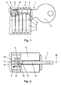
- FIG. 1 shows a cylinder lock with a cylinder core 13, a housing 3, and a flat key inserted therein 1.
- the key 1 has a key handle 2 and a key shank 4 on which here exemplified incision grooves 7 and on Key back 14 at the key tip 22 a control rib 10 is located.
- housing bores 5 which are aligned in the zero position of the castle with cylinder core 6 holes.
- spring-loaded split tumbler pins (not shown) which scan the notches 7 of the key 1.
- a cross-slide this 8 which is biased by a spring 9 in the direction of the housing 3.
- This slider 8 keys with its control recess 18 from the control rib 10, wherein above all the front control edge 12, the width of the control rib 10 and the position of the control rib 10 are queried on the key back 14.
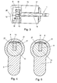
- FIGS. 2 and 3 each show a plan view of a cylinder core into which a flat key 1 according to the invention is inserted.
- the flat key 1 is not yet fully inserted into the keyway 17.
- the slider 8 is biased by the spring 9 in the direction of the housing.
- control rib 10 is arranged on the key back 14 on the key tip 22 to the left of the central longitudinal plane 25 and parallel thereto.
- FIG. 6 shows a slide 8 of a cylinder lock according to the invention in a side view with the control recess 18 and the guide edge 19.
- FIGS. 7 to 9 each show a plan view of a slide 8 with differently designed control recesses 18. Further, the spring support edge 20 is shown, via which the force of the spring 9 is transmitted to the slide.
- the width of the control recess 18 and the Ausappelungsmother 24 may be configured differently depending on the design, which significantly increases the possibilities of variation of the castle.
- the recess length 24 should be greater than 0 but less than the slide length 23, so that the front control edge 12 of the control rib 10 of the key 1 can be queried.
- the position along the central longitudinal plane 25 may also be different, as shown in FIGS. 8 and 9. In FIG. 8, the recess 18 is located on the left parallel to the central longitudinal plane 25 and in FIG. 9 on the right parallel to the central longitudinal plane 25.
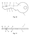
- Fig. 10 shows a flat key 1 according to the invention with a key handle 2 and a key shank 4.
- the shaft 4 are here, for example, incision grooves 7, which are scanned by divided tumblers in the cylinder lock.
- At the key back 14 at the key tip 22 is further a control rib 10 with a front control edge 12, and on both sides of each web edges 15th
- FIG. 11 shows a plan view of the flat key 1 from FIG. 10, wherein in this embodiment the control rib 10 is arranged on the left parallel to the central longitudinal plane 25. To increase the number of variations, the control rib 10 may also be arranged centrally or right parallel to the central longitudinal plane 25.
Abstract
Description
Die Erfindung betrifft ein Zylinderschloss mit darin verdrehbarem Zylinderkern, der einen Schlüsselkanal für einen Flachschlüssel und Abtastelemente für Einschnittfräsungen und/oder Steuerflächen des Schlüssels sowie Sperrelemente aufweist, die den Zylinderkern gegen Verdrehen blockieren oder freigeben.The invention relates to a cylinder lock with rotatable cylinder core, which has a key channel for a flat key and sensing elements for cutting grooves and / or control surfaces of the key and locking elements that block the cylinder core against rotation or release.
Weiters betrifft die Erfindung einen Flachschlüssel mit Einschnittfräsungen und/oder Steuerflächen an den Schlüsselschmalseiten und/oder Schlüsselflachseiten.Furthermore, the invention relates to a flat key with cut grooves and / or control surfaces on the key narrow sides and / or key flat sides.
Bekannt sind Zylinderschlösser, die mittels unterschiedlicher Zuhaltungen Einschnittfräsungen oder Steuerflächen an einem entsprechenden Flachschlüssel abtasten. Wesentlicher Vorteil derartiger Schlösser und Schlüssel ist die billige Herstellungsmöglichkeit sowie die relativ hohe Sperrsicherheit. Zur Verbesserung der Sperrsicherheit derartiger Schlösser ist es wünschenswert die Variationsmöglichkeiten am Schlüssel sowie des Schlosses zu erhöhen. Dies führt meist dazu, dass die Konstruktion der Schlösser immer aufwendiger wird, was sich nachteilig für die Funktionssicherheit der Schlösser auswirken kann, und zu höheren Produktionskosten führt.Cylinder locks are known which scan by means of different tumblers cutting cuts or control surfaces on a corresponding flat key. The main advantage of such locks and keys is the cheap production possibility and the relatively high locking security. To improve the locking security of such locks, it is desirable to increase the possibilities of variation on the key and the lock. This usually leads to the construction of the locks is becoming more complex, which can adversely affect the reliability of the locks, and leads to higher production costs.
Aufgabe der vorliegenden Erfindung ist es somit ein Zylinderschloss zu schaffen, welches die oben genannten Nachteile beseitigt und eine Erhöhung der Variationsmöglichkeiten erlaubt, wobei gleichzeitig die Schlosskonstruktion möglichst einfach bleiben soll und die Herstellungskosten gering gehalten werden. Weiters ist es Aufgabe der Erfindung einen entsprechenden Flachschlüssel für ein derartiges Zylinderschloss zu schaffen.Object of the present invention is thus to provide a cylinder lock, which eliminates the above-mentioned disadvantages and allows an increase in the possibilities of variation, at the same time the lock construction should remain as simple as possible and the manufacturing costs are kept low. It is also a task the invention to provide a corresponding flat key for such a cylinder lock.
Gelöst wird diese Aufgabe dadurch, dass oberhalb des Schlüsselkanals ein Schieber vorgesehen ist, welcher den Schlüsselkanal übergreift, wobei der Schieber an seiner dem Schlüsselkanal zugewandten Seite zumindest eine Steuerausnehmung aufweist, die mit entsprechenden Steuerrippen am Schlüsselrücken in Eingriff bringbar ist, und wobei der Schieber in seiner Ruhestellung mit entsprechenden Rastausnehmungen im Zylindergehäuse im Eingriff steht, und in die Freigabestellung bei richtigem Schlüssel quer zum Schlüsselkanal verschiebbar ist um den Zylinderkern gegen Verdrehen freizugeben.This object is achieved in that above the key channel, a slider is provided which engages over the keyway, wherein the slider has on its side facing the key channel at least one control recess which is engageable with corresponding control ribs on the key back, and wherein the slide in its rest position with corresponding recesses in the cylinder housing is engaged, and in the release position with the right key across the keyway is slidable to release the cylinder core against rotation.
Weiters wird ein entsprechender Flachschlüssel geschaffen, der am Schlüsselrücken eine sich in Längsrichtung in Richtung Schlüsselspitze erstreckende Steuerrippe aufweist, die eine vordere Steuerkante, sowie linke und rechte zur Schlüssellängsrichtung parallele Stegkanten aufweist.Furthermore, a corresponding flat key is provided which has a longitudinally extending in the direction of the key tip control rib on the back of the key, which has a front control edge, as well as left and right parallel to the key longitudinal web edges.
Ein Merkmal des erfindungsgemäßen Zylinderschlosses ist, dass der Schieber in einer Ausnehmung des Zylinderkerns angeordnet und mittels einer Feder in Richtung Zylindergehäuse vorgespannt ist. Die am Schieber vorhandene Steuerausnehmung ist in ihrer Länge und Breite variierbar, wobei die Länge der Steuerausnehmung kleiner als die Länge des Schiebers und die Breite der Steuerausnehmung kleiner oder gleich der Breite des Schlüsselkanals sein soll, und wobei weiters die Ausnehmung in Freigabestellung des Schiebers entlang der Mittellängsebene des Schlüsselkanals oder parallel dazu angeordnet ist. Wesentlicher Vorteil eines derartigen Schiebers ist es, dass er mit relativ geringem Aufwand den Schlüsselkanal übergreifend angeordnet werden kann, und dass durch die Variation der Länge, der Breite sowie der Position der Ausnehmung eine Erhöhung der Variationszahl des Schlosses erreicht wird.A feature of the cylinder lock according to the invention is that the slide is arranged in a recess of the cylinder core and biased by a spring in the direction of the cylinder housing. The existing on the slider control recess is variable in length and width, wherein the length of the control recess is smaller than the length of the slider and the width of the control recess should be less than or equal to the width of the keyway, and further wherein the recess in the release position of the slider along the Central longitudinal plane of the keyway or arranged parallel to it. The essential advantage of such a slider is that it can be arranged cross-over the key channel with relatively little effort, and that an increase in the number of variations of the lock is achieved by the variation of the length, the width and the position of the recess.
Ein weiteres Merkmal eines erfindungsgemäßen Zylinderschlosses ist es, dass die Steuerausnehmung eine Führungskante aufweist, die der Führung der entsprechenden Steuerrippen am Schlüsselrücken dient, wobei die Führungskante schräg oder abgerundet ausgebildet ist und in Ruhestellung über die Längsmittelebene des Schlüsselkanals ragt. Beim Einschieben eines Schlüssels mit entsprechender Steuerrippe am Schlüsselrücken wird also die Steuerrippe über die Führungskante geführt, wobei der Schieber entgegen der Kraft der Feder quer zum Schlüsselkanal verschoben wird und das Schloss, bei richtigem Schlüssel somit in Freigabestellung gebracht wird.Another feature of a cylinder lock according to the invention is that the control recess has a leading edge, which serves to guide the corresponding control ribs on the key back, wherein the leading edge is formed obliquely or rounded and protrudes in the rest position on the longitudinal center plane of the keyway. When inserting a key with a corresponding control rib on the spine, the control rib is thus guided over the leading edge, wherein the slide is moved against the force of the spring transversely to the key channel and the lock is thus brought in the release position with the right key.
Weitere erfindungsgemäße Merkmale des Flachschlüssels sind, dass sich die Steuerrippe entlang der Mittellängsebene oder parallel dazu entlang des Schlüsselrückens in Richtung Schlüsselspitze erstreckt, wobei sie bevorzugt mittig, links oder rechts der Mittellängsebene angeordnet ist.Further features of the flat key according to the invention are that the control rib extends along the central longitudinal plane or parallel thereto along the key back in the direction of the key tip, wherein it is preferably arranged centrally, left or right of the central longitudinal plane.
Die Steuerrippe kann in ihrer Breitevariierbar ausgeführt sein, wobei die Breite größer als 0 und geringer als die Breite des Schlüsselrückens ist. Die Steuerrippe kann in ihrer Länge, Breite sowie ihrer Position variiert werden, damit sie in die jeweiligen entsprechenden Steuerausnehmungen des Schiebers im Zylinderschloss passt.The control rib may be variable in width, the width being greater than 0 and less than the width of the key back. The control rib may be varied in length, width and position to fit within the respective corresponding control recesses of the slider in the cylinder lock.
Weitere Merkmale der Erfindung sind den Figuren, den Ansprüchen sowie der Beschreibung zu entnehmen.Further features of the invention can be taken from the figures, the claims and the description.
Fig. 1 zeigt einen schematischen Längsschnitt durch ein erfindungsgemäßes Zylinderschloss mit eingeschobenen Flachschlüssel. Fig. 2 zeigt eine Aufsicht auf ein Zylinderkern mit nicht vollständig eingeschobenen Flachschlüssel. Fig. 3 zeigt eine Aufsicht auf einen Zylinderkern mit vollständig eingeschobenen Flachschlüssel. Fig. 4 zeigt einen schematischen Querschnitt durch ein Zylinderschloss mit dem Schieber in Sperrstellung. Fig. 5 zeigt einen schematischen Querschnitt durch ein Zylinderschloss mit dem Schieber in Freigabestellung. Die Fig. 6 bis 9 zeigen verschiedene Ausführungsformen des Schiebers eines erfindungsgemäßen Zylinderschlosses. Fig. 10 zeigt eine Seitenansicht eines erfindungsgemäßen Flachschlüssels. Fig. 11 zeigt eine Aufsicht eines erfindungsgemäßen Flachschlüssels.Fig. 1 shows a schematic longitudinal section through an inventive cylinder lock with inserted flat key. Fig. 2 shows a plan view of a cylinder core with not completely inserted flat key. Fig. 3 shows a plan view of a cylinder core with fully inserted flat key. Fig. 4 shows a schematic cross section through a cylinder lock with the slider in the blocking position. Fig. 5 shows a schematic cross section through a cylinder lock with the slider in the release position. FIGS. 6 to 9 show various embodiments of the slider of a cylinder lock according to the invention. 10 shows a side view of a flat key according to the invention. 11 shows a plan view of a flat key according to the invention.
Der in Fig. 1 gezeigte schematische Längsschnitt zeigt ein Zylinderschloss mit einem Zylinderkern 13, einem Gehäuse 3, sowie einen darin eingeschobenen Flachschlüssel 1. Der Schlüssel 1 weist einen Schlüsselgriff 2 sowie einen Schlüsselschaft 4 auf, auf dem sich hier beispielhaft dargestellt Einschnittfräsungen 7 sowie am Schlüsselrücken 14 an der Schlüsselspitze 22 eine Steuerrippe 10 befindet.The schematic longitudinal section shown in Fig. 1 shows a cylinder lock with a
Im Gehäuse 3 befinden sich Gehäusebohrungen 5 welche in Nullstellung des Schlosses mit Zylinderkernbohrungen 6 fluchten. Innerhalb dieser Bohrungen 5, 6 befinden sich federbelastete geteilte Zuhaltestifte (nicht gezeigt), welche die Einschnittfräsungen 7 des Schlüssels 1 abtasten. Als weitere Zuhaltung befindet sich oberhalb des Schlüsselkanals 17 ein diesen übergreifender Schieber 8, welcher mittels einer Feder 9 in Richtung des Gehäuses 3 vorgespannt ist. Dieser Schieber 8 tastet mit seiner Steuerausnehmung 18 die Steuerrippe 10 ab, wobei vor allem die vordere Steuerkante 12, die Breite der Steuerrippe 10 sowie die Position der Steuerrippe 10 am Schlüsselrücken 14 abgefragt werden.In the
Die Fig. 2 und 3 zeigen jeweils eine Aufsicht auf einen Zylinderkern in den ein erfindungsgemäßer Flachschlüssel 1 eingeschoben wird. Bei der in Fig. 2 gezeigten Darstellung ist der Flachschlüssel 1 noch nicht vollständig in den Schlüsselkanal 17 eingeschoben. Der Schieber 8 wird durch die Feder 9 in Richtung des Gehäuses vorgespannt.2 and 3 each show a plan view of a cylinder core into which a
Bei dem dargestellten Schlüssel 1 ist die Steuerrippe 10 am Schlüsselrücken 14 an der Schlüsselspitze 22 links der Mittellängsebene 25 und parallel zu dieser angeordnet.In the illustrated
Wird nun der Schlüssel 1 weiter in den Schlüsselkanal 17 hineingeschoben, trifft die vordere Steuerkante 12 der Steuerrippe 10 auf die Führungskante 19, wodurch der Schieber 8 quer zum Schlüsselkanal 17 bewegt wird. Über die Steuerausnehmung 18 wird die Breite der Steuerrippe 10, die Tiefe, sowie die richtige Position entlang der Mittellängsebene 25 abgefragt. Bei voll eingeschobenem richtigen Schlüssel 1, wie dies in Fig. 3 gezeigt ist befindet sich der Schieber 8 in seiner Freigabestellung.Now, if the
Die Fig. 4 und 5 zeigen jeweils einen schematischen Querschnitt durch ein Zylinderschloss mit einem Gehäuse 3 einem Zylinderkern 13 und einem Schlüsselkanal 17. In Sperrstellung befindet sich der Schieber 8 in einer im Gehäuse befindlichen Rastausnehmung 21 in der er durch die Feder 9 gehalten wird und das Schloss gegen Verdrehen blockiert.4 and 5 each show a schematic cross section through a cylinder lock with a housing 3 a
Bei eingeschobenem richtigen Schlüssel 1 wird über die Steuerrippe 10, welche mit der Steuerausnehmung 18 in Eingriff steht, der Schieber 8 aus seiner Sperrposition heraus bewegt und quer zum Schlüsselkanal 17 verschoben, wodurch das Schloss freigegeben wird.When inserted
Fig. 6 zeigt einen Schieber 8 eines erfindungsgemäßen Zylinderschlosses in einer Seitenansicht mit der Steuerausnehmung 18 sowie der Führungskante 19.FIG. 6 shows a
Die Fig. 7 bis 9 zeigen jeweils eine Aufsicht auf einen Schieber 8 mit unterschiedlich ausgestalteten Steuerausnehmungen 18. Ferner ist die Federauflagekante 20 gezeigt, über welche die Kraft der Feder 9 auf den Schieber übertragen wird. Die Breite der Steuerausnehmung 18 sowie die Ausnehmungslänge 24 kann je nach Ausführung unterschiedlich ausgestaltet sein, was die Variationsmöglichkeiten des Schlosses wesentlich erhöht. Die Ausnehmungslänge 24 soll dabei größer als 0 jedoch geringer als die Schieberlänge 23 sein, damit die vordere Steuerkante 12 der Steuerrippe 10 des Schlüssels 1 abfragbar ist. Um die Variationszahl weiter zu erhöhen kann auch die Position entlang der Mittellängsebene 25 unterschiedlich sein, wie dies in den Fig. 8 und 9 gezeigt ist. In Fig. 8 befindet sich die Ausnehmung 18 links parallel zur Mittellängsebene 25 und in Fig. 9 rechts parallel der Mittellängsebene 25.7 to 9 each show a plan view of a
Fig. 10 zeigt einen erfindungsgemäßen Flachschlüssel 1 mit einem Schlüsselgriff 2 und einem Schlüsselschaft 4. Am Schaft 4 befinden sich hier beispielhafterweise Einschnittfräsungen 7, die von geteilten Zuhaltungen im Zylinderschloss abgetastet werden. Am Schlüsselrücken 14 an der Schlüsselspitze 22 befindet sich weiters eine Steuerrippe 10 mit einer vorderen Steuerkante 12, sowie zu beiden Seiten jeweils Stegkanten 15.Fig. 10 shows a
Die Fig. 11 zeigt eine Aufsicht auf den Flachschlüssel 1 aus Fig. 10, wobei bei dieser Ausführungsform die Steuerrippe 10 links parallel zur Mittellängsebene 25 angeordnet ist. Zur Erhöhung der Variationszahl kann die Steuerrippe 10 auch mittig oder rechts parallel zur Mittellängsebene 25 angeordnet sein.FIG. 11 shows a plan view of the
Claims (7)
Applications Claiming Priority (2)
| Application Number | Priority Date | Filing Date | Title |
|---|---|---|---|
| AT162006A AT503121B1 (en) | 2006-01-05 | 2006-01-05 | Cylinder lock has slide plate which moves crosswise of key channel to selectively lock cylinder core |
| AT0003706U AT9156U1 (en) | 2006-01-05 | 2006-01-19 | CYLINDER LOCK WITH SLIDER AND FLAT WRENCH WITH CONTROL RIB |
Publications (2)
| Publication Number | Publication Date |
|---|---|
| EP1806466A2 true EP1806466A2 (en) | 2007-07-11 |
| EP1806466A3 EP1806466A3 (en) | 2009-12-02 |
Family
ID=36424834
Family Applications (1)
| Application Number | Title | Priority Date | Filing Date |
|---|---|---|---|
| EP07000151A Withdrawn EP1806466A3 (en) | 2006-01-05 | 2007-01-05 | Cylinder lock with slide and flat key with guide rib |
Country Status (9)
| Country | Link |
|---|---|
| EP (1) | EP1806466A3 (en) |
| AT (1) | AT9156U1 (en) |
| AU (1) | AU2007200042A1 (en) |
| DE (1) | DE202006003870U1 (en) |
| FR (1) | FR2895763B3 (en) |
| GB (1) | GB2433960A (en) |
| IE (1) | IES20060234A2 (en) |
| NL (1) | NL2000047C1 (en) |
| RU (1) | RU2006147214A (en) |
Cited By (2)
| Publication number | Priority date | Publication date | Assignee | Title |
|---|---|---|---|---|
| CN112673143A (en) * | 2018-09-13 | 2021-04-16 | 塔莱雷斯·埃斯科瑞扎公司 | Lock system with key and lock cylinder |
| EP4047161A1 (en) * | 2021-02-22 | 2022-08-24 | ASSA ABLOY (Schweiz) AG | Key, key and locking cylinder |
Families Citing this family (4)
| Publication number | Priority date | Publication date | Assignee | Title |
|---|---|---|---|---|
| DE102010001909A1 (en) * | 2010-02-12 | 2011-08-18 | DORMA GmbH + Co. KG, 58256 | lock cylinder |
| FR2962752B1 (en) * | 2010-07-13 | 2012-08-17 | Assa Abloy Aube Anjou | LOCKING CYLINDER FOR FLAT WRENCH |
| GB2578865B (en) * | 2018-10-01 | 2022-06-15 | Inkster David | Improvements in or relating to security |
| DE102020117226A1 (en) | 2020-06-30 | 2021-12-30 | ABUS August Bremicker Söhne Kommanditgesellschaft | Lock cylinder, locking device, locking system, key and key blank |
Citations (5)
| Publication number | Priority date | Publication date | Assignee | Title |
|---|---|---|---|---|
| US758027A (en) * | 1903-07-22 | 1904-04-19 | Yale & Towne Mfg Co | Pin-lock. |
| US1958603A (en) * | 1932-11-29 | 1934-05-15 | William T Bacon | Lock |
| US3590615A (en) * | 1970-02-16 | 1971-07-06 | Eaton Yale & Towne | Antipick lock |
| DE3004993A1 (en) * | 1980-02-11 | 1981-08-20 | C. Ed. Schulte GmbH, 5628 Velbert | Rotary cylinder lock - has extra cut=outs in slide gripped by key rear permitting more variation |
| WO2006066019A2 (en) * | 2004-12-14 | 2006-06-22 | Stanley Security Solutions, Inc. | Key core |
Family Cites Families (2)
| Publication number | Priority date | Publication date | Assignee | Title |
|---|---|---|---|---|
| DE10031972A1 (en) * | 2000-06-30 | 2002-01-10 | Winkhaus Fa August | Key for profile lock cylinder has control curve in cut-out in rear of key with part of control curve for holding supplementary tumbler immediately opposite notch in front of key |
| DE10050460A1 (en) * | 2000-10-12 | 2002-04-25 | Winkhaus Fa August | Key for profiled lock cylinder includes complementary tumbler moved by drive with swivel drive element |
-
2006
- 2006-01-19 AT AT0003706U patent/AT9156U1/en not_active IP Right Cessation
- 2006-03-11 DE DE202006003870U patent/DE202006003870U1/en not_active Expired - Lifetime
- 2006-03-24 FR FR0602572A patent/FR2895763B3/en not_active Expired - Fee Related
- 2006-03-27 IE IE20060234A patent/IES20060234A2/en not_active IP Right Cessation
- 2006-03-30 GB GB0606318A patent/GB2433960A/en not_active Withdrawn
- 2006-04-03 NL NL2000047A patent/NL2000047C1/en not_active IP Right Cessation
- 2006-12-28 RU RU2006147214/12A patent/RU2006147214A/en not_active Application Discontinuation
-
2007
- 2007-01-05 AU AU2007200042A patent/AU2007200042A1/en not_active Abandoned
- 2007-01-05 EP EP07000151A patent/EP1806466A3/en not_active Withdrawn
Patent Citations (5)
| Publication number | Priority date | Publication date | Assignee | Title |
|---|---|---|---|---|
| US758027A (en) * | 1903-07-22 | 1904-04-19 | Yale & Towne Mfg Co | Pin-lock. |
| US1958603A (en) * | 1932-11-29 | 1934-05-15 | William T Bacon | Lock |
| US3590615A (en) * | 1970-02-16 | 1971-07-06 | Eaton Yale & Towne | Antipick lock |
| DE3004993A1 (en) * | 1980-02-11 | 1981-08-20 | C. Ed. Schulte GmbH, 5628 Velbert | Rotary cylinder lock - has extra cut=outs in slide gripped by key rear permitting more variation |
| WO2006066019A2 (en) * | 2004-12-14 | 2006-06-22 | Stanley Security Solutions, Inc. | Key core |
Cited By (2)
| Publication number | Priority date | Publication date | Assignee | Title |
|---|---|---|---|---|
| CN112673143A (en) * | 2018-09-13 | 2021-04-16 | 塔莱雷斯·埃斯科瑞扎公司 | Lock system with key and lock cylinder |
| EP4047161A1 (en) * | 2021-02-22 | 2022-08-24 | ASSA ABLOY (Schweiz) AG | Key, key and locking cylinder |
Also Published As
| Publication number | Publication date |
|---|---|
| RU2006147214A (en) | 2008-07-10 |
| EP1806466A3 (en) | 2009-12-02 |
| FR2895763A3 (en) | 2007-07-06 |
| AU2007200042A1 (en) | 2007-07-19 |
| NL2000047C1 (en) | 2006-07-05 |
| AT9156U1 (en) | 2007-05-15 |
| IES20060234A2 (en) | 2006-10-18 |
| GB2433960A (en) | 2007-07-11 |
| DE202006003870U1 (en) | 2006-07-06 |
| FR2895763B3 (en) | 2007-11-09 |
| GB0606318D0 (en) | 2006-05-10 |
Similar Documents
| Publication | Publication Date | Title |
|---|---|---|
| EP0335069B1 (en) | Flat key for cylinder locks, and cylinder lock for this key | |
| EP2310598B1 (en) | Cylinder lock with cylinder housing and flat key for a cylinder lock | |
| EP2314807B1 (en) | Locking system | |
| EP1712714B1 (en) | Combination of a flat key and a cylinder lock | |
| EP1806466A2 (en) | Cylinder lock with slide and flat key with guide rib | |
| EP1816288B1 (en) | Cylinder lock and flat key | |
| EP2454429B1 (en) | Locking device | |
| EP3155191B1 (en) | Cylinder lock | |
| DE102012106326A1 (en) | Lock cylinder with associated key | |
| EP2792822B1 (en) | Coding via blocking bar | |
| DE202006003869U1 (en) | Cylinder lock and flat key | |
| EP2360334A2 (en) | Locking cylinder | |
| AT502746B1 (en) | CYLINDER LOCK AND FLAT KEY | |
| DE2135106B2 (en) | Cylinder lock with paired tumbler plates - is operated by key with actuating ridge faces on both sides | |
| AT503166B1 (en) | Cylindrical lock comprises cylindrical core pins formed on the end protruding into the key channel as scanning protrusions which are narrower than the diameter of the core pins and are aligned in the longitudinal direction of the channel | |
| EP2765260B1 (en) | Locking cylinder | |
| AT503121B1 (en) | Cylinder lock has slide plate which moves crosswise of key channel to selectively lock cylinder core | |
| DE102011000443B4 (en) | Locking cylinder in particular for actuating a switching mechanism | |
| AT503051B1 (en) | Cylinder lock, has set of control profile slots brought in interference at flat sides of key and control plate is in interference with locking recess in cylinder housing in normal position and key is adjustable in core in release position | |
| AT9229U1 (en) | CYLINDER LOCK AND FLAT KEY | |
| DE2930425A1 (en) | CYLINDLE LOCK | |
| EP4253699A1 (en) | Key for a locking cylinder and locking cylinder for such a key | |
| EP2952656B1 (en) | Profiled cylinder with a cylinder housing | |
| EP4119750A1 (en) | Locking cylinder and locking system |
Legal Events
| Date | Code | Title | Description |
|---|---|---|---|
| PUAI | Public reference made under article 153(3) epc to a published international application that has entered the european phase |
Free format text: ORIGINAL CODE: 0009012 |
|
| AK | Designated contracting states |
Kind code of ref document: A2 Designated state(s): AT BE BG CH CY CZ DE DK EE ES FI FR GB GR HU IE IS IT LI LT LU LV MC NL PL PT RO SE SI SK TR |
|
| AX | Request for extension of the european patent |
Extension state: AL BA HR MK YU |
|
| PUAL | Search report despatched |
Free format text: ORIGINAL CODE: 0009013 |
|
| AK | Designated contracting states |
Kind code of ref document: A3 Designated state(s): AT BE BG CH CY CZ DE DK EE ES FI FR GB GR HU IE IS IT LI LT LU LV MC NL PL PT RO SE SI SK TR |
|
| AX | Request for extension of the european patent |
Extension state: AL BA HR MK RS |
|
| AKY | No designation fees paid | ||
| REG | Reference to a national code |
Ref country code: DE Ref legal event code: 8566 |
|
| STAA | Information on the status of an ep patent application or granted ep patent |
Free format text: STATUS: THE APPLICATION IS DEEMED TO BE WITHDRAWN |
|
| 18D | Application deemed to be withdrawn |
Effective date: 20100603 |