EP2149478A2 - Vorrichtung zur Gestattung oder Unterdrückung der Auslösung eines Airbags mit geringem Risiko - Google Patents
Vorrichtung zur Gestattung oder Unterdrückung der Auslösung eines Airbags mit geringem Risiko Download PDFInfo
- Publication number
- EP2149478A2 EP2149478A2 EP09163095A EP09163095A EP2149478A2 EP 2149478 A2 EP2149478 A2 EP 2149478A2 EP 09163095 A EP09163095 A EP 09163095A EP 09163095 A EP09163095 A EP 09163095A EP 2149478 A2 EP2149478 A2 EP 2149478A2
- Authority
- EP
- European Patent Office
- Prior art keywords
- load
- seat
- deployment
- sensor
- airbag
- Prior art date
- Legal status (The legal status is an assumption and is not a legal conclusion. Google has not performed a legal analysis and makes no representation as to the accuracy of the status listed.)
- Withdrawn
Links
Images



Classifications
-
- B—PERFORMING OPERATIONS; TRANSPORTING
- B60—VEHICLES IN GENERAL
- B60R—VEHICLES, VEHICLE FITTINGS, OR VEHICLE PARTS, NOT OTHERWISE PROVIDED FOR
- B60R21/00—Arrangements or fittings on vehicles for protecting or preventing injuries to occupants or pedestrians in case of accidents or other traffic risks
- B60R21/01—Electrical circuits for triggering passive safety arrangements, e.g. airbags, safety belt tighteners, in case of vehicle accidents or impending vehicle accidents
- B60R21/015—Electrical circuits for triggering passive safety arrangements, e.g. airbags, safety belt tighteners, in case of vehicle accidents or impending vehicle accidents including means for detecting the presence or position of passengers, passenger seats or child seats, and the related safety parameters therefor, e.g. speed or timing of airbag inflation in relation to occupant position or seat belt use
- B60R21/01512—Passenger detection systems
- B60R21/01544—Passenger detection systems detecting seat belt parameters, e.g. length, tension or height-adjustment
- B60R21/0155—Passenger detection systems detecting seat belt parameters, e.g. length, tension or height-adjustment sensing belt tension
-
- B—PERFORMING OPERATIONS; TRANSPORTING
- B60—VEHICLES IN GENERAL
- B60R—VEHICLES, VEHICLE FITTINGS, OR VEHICLE PARTS, NOT OTHERWISE PROVIDED FOR
- B60R21/00—Arrangements or fittings on vehicles for protecting or preventing injuries to occupants or pedestrians in case of accidents or other traffic risks
- B60R21/01—Electrical circuits for triggering passive safety arrangements, e.g. airbags, safety belt tighteners, in case of vehicle accidents or impending vehicle accidents
- B60R21/015—Electrical circuits for triggering passive safety arrangements, e.g. airbags, safety belt tighteners, in case of vehicle accidents or impending vehicle accidents including means for detecting the presence or position of passengers, passenger seats or child seats, and the related safety parameters therefor, e.g. speed or timing of airbag inflation in relation to occupant position or seat belt use
- B60R21/01512—Passenger detection systems
- B60R21/01516—Passenger detection systems using force or pressure sensing means
- B60R21/0152—Passenger detection systems using force or pressure sensing means using strain gauges
Definitions
- the present invention relates to automatic suppression of airbag deployment, and more particularly to an apparatus for determining the suppression status of a low risk deployment airbag based on detected occupant load and seat belt tension.
- Automatic suppression systems have primarily been used in connection with conventional airbags to minimize the risk of deployment-related injuries to out-of-position occupants and small children, especially infants in rear-facing infant seats.
- the approach has been to gather sufficient information to be able to both detect and characterize seat occupants, and to allow or suppress deployment based on the occupant characterization.
- the automatic suppression function is less critical in vehicles equipped with low risk deployment airbags that have been designed to minimize deployment-related injuries to out-of-position occupants and small children, and significant effort has been expended to scale back both the cost and complexity of automatic suppression systems for such vehicles. Accordingly, what is needed is an effective but low-cost automatic suppression system suitable for use in connection with low risk deployment airbags.
- the present invention is directed to a low-cost apparatus for allowing or suppressing deployment of a low risk deployment airbag based solely on occupant seat load and seat belt tension.
- Seat load and belt tension measurements are obtained from low-cost sensors; and an airbag control unit suppresses airbag deployment when the occupant load is below a specified load threshold or the belt tension is above a specified tension threshold, and otherwise allows airbag deployment.
- the sensors are preferably switch-based so that the signals provided to the airbag control unit are in the form of differential electrical currents, and only two wires are needed to interface each sensor to the airbag control unit.
- the sensor signals can be provided to the airbag control unit in the form of differential electrical voltages; in this case, three wires are needed to interface each sensor to the airbag control unit.
- FIG. 1 is an illustration of a vehicle seat with seat load and belt tension sensors
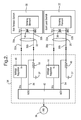
- FIG. 2 is a block diagram of an automatic suppression apparatus according to a first embodiment of this invention, including an airbag control unit having a microprocessor-based signal processor;
- FIG. 3 is a block diagram of an automatic suppression apparatus according to a second embodiment of this invention, including an airbag control unit having a microprocessor-based signal processor; and
- FIG. 4 is a logic flow diagram representative of a software routine executed by the signal processors of FIGS. 2-3 according to this invention.
- the reference numeral 10 generally designates a front passenger seat of a vehicle.
- the seat 10 is anchored to the passenger compartment floor 12, as are the lap end of seat belt 14 and the buckle receptacle 16.
- the shoulder end of seat belt 14 is routed through a hangar 18 and into a floor-mounted retractor mechanism 20, per conventional practice.
- a seat load sensor 22 disposed between the bottom cushion 24 and frame 26 is responsive to occupant weight applied to cushion 24, and provides a load-related electrical output signal via the wire pair 28.
- a belt tension sensor 30 disposed in the buckle receptacle 16 is responsive to the tension applied to seat belt 14, and provides a tension-related electrical output signal via the wire pair 32.
- the load-related and tension related output signals on wire pairs 28 and 32 are supplied to an airbag control unit (ACU) 34 that controls deployment of at least one low risk deployment airbag 36 for protection of the seat occupant during a sufficiently severe crash event.
- ACU airbag control unit
- the seat load sensor 22 may be located on the top surface of cushion 24, in cushion 24, or integrated into the seat frame 26; and the belt tension sensor 30 may be located in the retractor mechanism 20 or integrated into the belt 14.
- the particular structure and sensing technology of the sensors 22 and 30 are not necessarily dictated by this invention.
- the seat load sensor 22 may include a sensing element responsive to pressure, flexure, deflection or strain; and the belt tension sensor 30 may include a strain gauge or a magnetic flux responsive sensing element.
- the sensors 22 and 30 are preferably configured as switch elements so that the detected load or tension information can be conveyed to the airbag control unit 34 with only two wires per sensor. Minimizing the number of wires in the wiring harness for airbag control unit 34 serves to minimize component cost and to reduce the required connector insertion force.
- FIG. 2 illustrates a first and preferred embodiment of the present invention in which the sensors 22 and 30 are both configured as switch elements (as signified by the contacts 38 and 40) so that the load-related and tension-related output signals are supplied to airbag control unit 34 via the wire pairs 28 and 32, respectively.
- the sensors 22 and 30 are calibrated to change output states (with suitable hysteresis) at specified seat load and tension thresholds.
- the seat load sensor 22 may be calibrated so that its output state is effectively open when the weight applied to seat cushion 24 exceeds 21 kilograms (46 pounds), and effectively closed when the weight applied to cushion 24 is less than 19 kilograms (42 pounds).
- the belt tension sensor 30 may be calibrated so that its output state is effectively open when the tension in seat belt 14 exceeds 5.5 kilograms (12 pounds), and effectively closed when the tension in seat belt 14 is less than 4.5 kilograms (10 pounds).
- the airbag control unit (ACU) 34 includes a signal processor 42 (a microprocessor or digital signal processor, for example), first and second voltage regulators 44 and 46, and first and second shunt resistors 48 and 50.
- the voltage regulator 44 receives a supply voltage Vcc from signal processor 42, and supplies a logic-level switch voltage V+ to the power terminal 22a of sensor 22 via one wire 28a of the wire pair 28.
- voltage regulator 46 receives a supply voltage Vcc from signal processor 42, and supplies a logic-level switch voltage V+ to power terminal 30a of sensor 30 via one wire 32a of the wire pair 32.
- the signal terminal 22b of sensor 22 is coupled to ACU ground voltage 52 through the shunt resistor 48, and the signal terminal 30b of sensor 30 is coupled to ACU ground voltage 52 through the shunt resistor 50.
- the high-side voltage of shunt resistor 48 is supplied to a first analog input port (A/D1) of signal processor 42 via line 54, and the high-side voltage of shunt resistor 50 is supplied to a second analog input port (A/D2) of signal processor 42 via line 56.
- the load-related and tension-related output signals of sensors 22 and 30 may thus be viewed as differential current signals because the current through the respective shunt resistors 48, 50 (and hence, the voltage supplied to the respective input ports A/D1, A/D2) has one of two different values or levels depending on the logic state of the switch-based sensor 22, 30. And as indicated above, signal processor 42 may interpret the two levels as LOW or HIGH levels of the sensed parameter.
- FIG. 3 illustrates a second embodiment of the present invention in which the sensors 22 and 30 are both configured to provide continuously variable output signals instead of switched output signals.
- the airbag control unit signal processor 42 is programmed to determine if the sensed parameters have HIGH or LOW values for purposes of determining the suppression status of LRD airbag 36.
- the sensors 22 and 30 are each coupled to processor 42 via a set 58, 60 of three-wires.
- processor 42 provides reference and ground voltages via wires 58a and 58b, and sensor 22 supplies an output signal (LOAD) to the first analog input port (A/D1) of processor 42 via wire 58c.
- processor 42 provides reference and ground voltages to sensor 30 via wires 60a and 60b, and sensor 30 supplies an output signal (BTS) to the second analog input port (A/D2) of processor 42 via wire 60c.
- the sensor output voltage can be viewed as a differential voltage with respect to the supplied ground voltage, and processor 42 characterizes the signal levels as HIGH or LOW by comparing the signals to calibrated thresholds.
- the flow diagram of FIG. 4 represents a software routine executed by the processor 42 of airbag controller 34 for determining the appropriate suppression status for LRD airbag 36.
- the routine may be periodically executed, or executed in response to detected changes in the operating status of the vehicle such as changes in ignition switch position or the status of a door closure switch.
- the present invention provides an effective but low-cost automatic suppression system for a low risk deployment airbag. While the invention has been described with respect to the illustrated embodiments, it is recognized that numerous modifications and variations in addition to those mentioned herein will occur to those skilled in the art.
- the sensor inputs can be supplied to an occupant sensing unit, which in turn supplies the determined suppression status to an airbag control unit, and so on. Accordingly, it is intended that the invention not be limited to the disclosed embodiment, but that it have the full scope permitted by the language of the following claims.
Landscapes
- Engineering & Computer Science (AREA)
- Mechanical Engineering (AREA)
- Air Bags (AREA)
Applications Claiming Priority (1)
| Application Number | Priority Date | Filing Date | Title |
|---|---|---|---|
| US12/221,205 US20100025974A1 (en) | 2008-07-31 | 2008-07-31 | Apparatus for allowing or suppressing deployment of a low risk deployment airbag |
Publications (2)
| Publication Number | Publication Date |
|---|---|
| EP2149478A2 true EP2149478A2 (de) | 2010-02-03 |
| EP2149478A3 EP2149478A3 (de) | 2010-09-01 |
Family
ID=41226023
Family Applications (1)
| Application Number | Title | Priority Date | Filing Date |
|---|---|---|---|
| EP09163095A Withdrawn EP2149478A3 (de) | 2008-07-31 | 2009-06-18 | Vorrichtung zur Gestattung oder Unterdrückung der Auslösung eines Airbags mit geringem Risiko |
Country Status (2)
| Country | Link |
|---|---|
| US (1) | US20100025974A1 (de) |
| EP (1) | EP2149478A3 (de) |
Cited By (1)
| Publication number | Priority date | Publication date | Assignee | Title |
|---|---|---|---|---|
| DE102023103210A1 (de) | 2023-02-09 | 2024-08-14 | Audi Aktiengesellschaft | Vorrichtung zur Aktivierung/Deaktivierung einer Airbagfunktion in einem Fahrzeug |
Family Cites Families (33)
| Publication number | Priority date | Publication date | Assignee | Title |
|---|---|---|---|---|
| US5474327A (en) * | 1995-01-10 | 1995-12-12 | Delco Electronics Corporation | Vehicle occupant restraint with seat pressure sensor |
| US6260879B1 (en) * | 1997-05-12 | 2001-07-17 | Automotive Systems Laboratory, Inc. | Air bag suppression system using a weight sensor, a seat belt tension monitor, and a capacitive sensor in the instrument panel |
| JPH1170855A (ja) * | 1997-08-28 | 1999-03-16 | Aisin Seiki Co Ltd | シートベルトウォーニング装置 |
| US5987370A (en) * | 1997-09-03 | 1999-11-16 | Delco Electronics Corp. | Vehicle occupant weight estimation apparatus having fluid-filled seat bladder |
| US6046511A (en) * | 1998-05-08 | 2000-04-04 | Delco Electronics Corporation | Fault tolerant power supply and bus topology for a distributed architecture supplemental restraint system |
| EP1318043B1 (de) * | 1999-01-27 | 2009-02-25 | The Furukawa Electric Co., Ltd. | Vorrichtung zur Erfassung der Insassen eines Fahrzeuges |
| US6246936B1 (en) * | 1999-10-05 | 2001-06-12 | Delphi Technologies, Inc. | Vehicle occupant characterization method based on sensed occupant weight |
| US6581960B1 (en) * | 1999-12-14 | 2003-06-24 | Ford Global Technologies, Llc | Seat belt occupant sensor |
| US6554318B2 (en) * | 2000-01-12 | 2003-04-29 | Delphi Technologies, Inc. | Seat belt tension sensor |
| US6320494B1 (en) * | 2000-01-18 | 2001-11-20 | Honeywell International Inc. | Full duplex communication system with power transfer on one pair of conductors |
| JP2003533399A (ja) * | 2000-05-12 | 2003-11-11 | シーメンス ヴィディーオー オートモーティヴ コーポレイション | シートベルトにかかる力のセンサー装置 |
| US6636792B2 (en) * | 2000-09-29 | 2003-10-21 | Siemens Vdo Automotive Corporation | Weight classification system |
| JP2002274326A (ja) * | 2001-03-16 | 2002-09-25 | Takata Corp | 乗員センサ |
| JP2003040078A (ja) * | 2001-08-01 | 2003-02-13 | Denso Corp | エアバッグ作動制御システム |
| JP2003095060A (ja) * | 2001-09-25 | 2003-04-03 | Aisin Seiki Co Ltd | 乗員判定装置 |
| US6679524B2 (en) * | 2001-11-14 | 2004-01-20 | Delphi Technologies, Inc. | Tension sensing assembly |
| US6796192B2 (en) * | 2001-12-19 | 2004-09-28 | Delphi Technologies, Inc. | Pass through seat restraint tension sensing assembly |
| US6850825B2 (en) * | 2002-02-04 | 2005-02-01 | Delphi Technologies, Inc. | Method for suppressing deployment of an inflatable restraint based on sensed occupant weight |
| US6662094B2 (en) * | 2002-02-15 | 2003-12-09 | Delphi Technologies, Inc. | Method of initially characterizing an occupant of a vehicle seat based on weight and seat belt tension |
| US6749038B2 (en) * | 2002-02-20 | 2004-06-15 | Delphi Technologies, Inc. | Tension sensing assembly |
| US6605877B1 (en) * | 2002-02-26 | 2003-08-12 | Delphi Technologies, Inc. | Restraint system interface arrangement for a seat belt tension sensor |
| US6587770B1 (en) * | 2002-02-26 | 2003-07-01 | Delphi Technologies, Inc. | Vehicle seat occupant weight estimation method with floor weight compensation |
| US6868745B2 (en) * | 2002-05-07 | 2005-03-22 | Delphi Technologies, Inc. | Seat restraint buckle and tension sensing assembly |
| WO2004013588A1 (en) * | 2002-08-01 | 2004-02-12 | The Johns Hopkins University | Seat-based weight sensor |
| US6889146B2 (en) * | 2002-09-04 | 2005-05-03 | Delphi Technologies, Inc. | Seat belt tension determination using multiple belt tension sensors |
| US6851503B2 (en) * | 2002-10-01 | 2005-02-08 | Delphi Technologies, Inc. | Seat belt tension sensor assembly |
| US7347452B2 (en) * | 2003-04-23 | 2008-03-25 | Delphi Technologies, Inc. | Tension sensing assembly |
| JP2005145087A (ja) * | 2003-11-11 | 2005-06-09 | Takata Corp | シートベルト装置 |
| JP2005219689A (ja) * | 2004-02-09 | 2005-08-18 | Denso Corp | 乗員保護装置の制御システム |
| JP4285281B2 (ja) * | 2004-03-08 | 2009-06-24 | 株式会社デンソー | 車両用シートベルト警報装置 |
| JP2008501572A (ja) * | 2004-06-07 | 2008-01-24 | シーアイエス テック,エルエルシー | 低危険展開式助手席エアーバッグシステム |
| EP1755916B1 (de) * | 2004-06-07 | 2015-04-22 | Delphi Technologies Inc. | Kindergurtsystem mit gewichtssensor |
| US7519461B2 (en) * | 2005-11-02 | 2009-04-14 | Lear Corporation | Discriminate input system for decision algorithm |
-
2008
- 2008-07-31 US US12/221,205 patent/US20100025974A1/en not_active Abandoned
-
2009
- 2009-06-18 EP EP09163095A patent/EP2149478A3/de not_active Withdrawn
Cited By (2)
| Publication number | Priority date | Publication date | Assignee | Title |
|---|---|---|---|---|
| DE102023103210A1 (de) | 2023-02-09 | 2024-08-14 | Audi Aktiengesellschaft | Vorrichtung zur Aktivierung/Deaktivierung einer Airbagfunktion in einem Fahrzeug |
| US12304412B2 (en) | 2023-02-09 | 2025-05-20 | Audi Ag | Device for activating/deactivating an airbag function in a vehicle |
Also Published As
| Publication number | Publication date |
|---|---|
| EP2149478A3 (de) | 2010-09-01 |
| US20100025974A1 (en) | 2010-02-04 |
Similar Documents
| Publication | Publication Date | Title |
|---|---|---|
| US6264236B1 (en) | Occupant restraint system | |
| US6282473B1 (en) | System and method for controlling a vehicle occupant protection device | |
| US6084314A (en) | Integrated occupant protection system | |
| US10035432B2 (en) | Seat occupancy determination apparatus | |
| JP2004098785A (ja) | 車両乗員検知装置 | |
| US20030158643A1 (en) | Method of initially characterizing an occupant of a vehicle seat based on weight and seat belt tension | |
| JP3358517B2 (ja) | 乗員検知システム及び乗員検知方法 | |
| KR20020029778A (ko) | 시트 착석자 중량을 측정하기 위한 방법 및 장치 | |
| US6971669B2 (en) | Passenger discriminating apparatus | |
| EP1580064B1 (de) | Fahrzeuginsassen-Klassifizierungssystem. | |
| EP1612109B1 (de) | Verfahren und Vorrichtung zum Erkennen eines rückwärts gerichteten Kindersitzes | |
| US7009509B2 (en) | Occupant weight detecting device | |
| US7866691B2 (en) | Occupant classifying device for vehicle seat | |
| JP4007070B2 (ja) | シート上荷重検出装置 | |
| KR20090002892A (ko) | 차량용 승객 식별 시스템 | |
| US20050173904A1 (en) | Control system for vehicle occupant protection apparatus | |
| US7742859B2 (en) | Method for setting, calibrating, and verifying an occupation classification system threshold | |
| US20150166000A1 (en) | Seat occupancy determination device | |
| EP2149478A2 (de) | Vorrichtung zur Gestattung oder Unterdrückung der Auslösung eines Airbags mit geringem Risiko | |
| JP3458323B2 (ja) | 乗員検知システム | |
| US6963287B2 (en) | Occupant weight detecting device | |
| US20140297132A1 (en) | Occupant determination apparatus using load sensor | |
| JP2000296757A (ja) | 車両乗員保護装置の作動制御システム | |
| KR101406431B1 (ko) | 교차적 스위칭에 따라 직류 전압과 교류 전압을 공급하는 차량용 승객 식별 장치 | |
| KR20100060538A (ko) | 시트 히터와 승객 센서로 교차적 스위칭에 따라 직류 전압과 교류 전압을 공급하는 차량용 승객 식별 장치 |
Legal Events
| Date | Code | Title | Description |
|---|---|---|---|
| PUAI | Public reference made under article 153(3) epc to a published international application that has entered the european phase |
Free format text: ORIGINAL CODE: 0009012 |
|
| AK | Designated contracting states |
Kind code of ref document: A2 Designated state(s): AT BE BG CH CY CZ DE DK EE ES FI FR GB GR HR HU IE IS IT LI LT LU LV MC MK MT NL NO PL PT RO SE SI SK TR |
|
| AX | Request for extension of the european patent |
Extension state: AL BA RS |
|
| PUAL | Search report despatched |
Free format text: ORIGINAL CODE: 0009013 |
|
| AK | Designated contracting states |
Kind code of ref document: A3 Designated state(s): AT BE BG CH CY CZ DE DK EE ES FI FR GB GR HR HU IE IS IT LI LT LU LV MC MK MT NL NO PL PT RO SE SI SK TR |
|
| AX | Request for extension of the european patent |
Extension state: AL BA RS |
|
| STAA | Information on the status of an ep patent application or granted ep patent |
Free format text: STATUS: THE APPLICATION IS DEEMED TO BE WITHDRAWN |
|
| 18D | Application deemed to be withdrawn |
Effective date: 20110302 |