EP2149388B1 - Appareil manuel destiné au perçage local d'une peau humaine ou animale, module d'entraînement, module d'aiguille et procédé d'accouplement - Google Patents
Appareil manuel destiné au perçage local d'une peau humaine ou animale, module d'entraînement, module d'aiguille et procédé d'accouplement Download PDFInfo
- Publication number
- EP2149388B1 EP2149388B1 EP08013836A EP08013836A EP2149388B1 EP 2149388 B1 EP2149388 B1 EP 2149388B1 EP 08013836 A EP08013836 A EP 08013836A EP 08013836 A EP08013836 A EP 08013836A EP 2149388 B1 EP2149388 B1 EP 2149388B1
- Authority
- EP
- European Patent Office
- Prior art keywords
- needle
- unit
- drive unit
- actuating element
- coupling
- Prior art date
- Legal status (The legal status is an assumption and is not a legal conclusion. Google has not performed a legal analysis and makes no representation as to the accuracy of the status listed.)
- Not-in-force
Links
- 238000010168 coupling process Methods 0.000 title claims description 53
- 230000008878 coupling Effects 0.000 title claims description 50
- 238000005859 coupling reaction Methods 0.000 title claims description 50
- 238000000034 method Methods 0.000 title claims description 10
- 241001465754 Metazoa Species 0.000 title claims description 7
- 238000006073 displacement reaction Methods 0.000 claims description 30
- 230000003252 repetitive effect Effects 0.000 claims description 15
- 230000007246 mechanism Effects 0.000 claims description 13
- 239000013543 active substance Substances 0.000 claims description 3
- 239000012528 membrane Substances 0.000 description 7
- 238000003032 molecular docking Methods 0.000 description 3
- 239000000126 substance Substances 0.000 description 3
- 230000009471 action Effects 0.000 description 2
- 239000013013 elastic material Substances 0.000 description 2
- 238000003780 insertion Methods 0.000 description 2
- 230000037431 insertion Effects 0.000 description 2
- 230000008569 process Effects 0.000 description 2
- 230000007704 transition Effects 0.000 description 2
- 208000027418 Wounds and injury Diseases 0.000 description 1
- 239000008280 blood Substances 0.000 description 1
- 210000004369 blood Anatomy 0.000 description 1
- 239000002537 cosmetic Substances 0.000 description 1
- 230000006378 damage Effects 0.000 description 1
- 230000001419 dependent effect Effects 0.000 description 1
- 230000005489 elastic deformation Effects 0.000 description 1
- 238000005516 engineering process Methods 0.000 description 1
- 208000014674 injury Diseases 0.000 description 1
- 230000003993 interaction Effects 0.000 description 1
- 230000007480 spreading Effects 0.000 description 1
Images


Classifications
-
- A—HUMAN NECESSITIES
- A61—MEDICAL OR VETERINARY SCIENCE; HYGIENE
- A61M—DEVICES FOR INTRODUCING MEDIA INTO, OR ONTO, THE BODY; DEVICES FOR TRANSDUCING BODY MEDIA OR FOR TAKING MEDIA FROM THE BODY; DEVICES FOR PRODUCING OR ENDING SLEEP OR STUPOR
- A61M37/00—Other apparatus for introducing media into the body; Percutany, i.e. introducing medicines into the body by diffusion through the skin
- A61M37/0076—Tattooing apparatus
-
- A—HUMAN NECESSITIES
- A61—MEDICAL OR VETERINARY SCIENCE; HYGIENE
- A61M—DEVICES FOR INTRODUCING MEDIA INTO, OR ONTO, THE BODY; DEVICES FOR TRANSDUCING BODY MEDIA OR FOR TAKING MEDIA FROM THE BODY; DEVICES FOR PRODUCING OR ENDING SLEEP OR STUPOR
- A61M37/00—Other apparatus for introducing media into the body; Percutany, i.e. introducing medicines into the body by diffusion through the skin
-
- Y—GENERAL TAGGING OF NEW TECHNOLOGICAL DEVELOPMENTS; GENERAL TAGGING OF CROSS-SECTIONAL TECHNOLOGIES SPANNING OVER SEVERAL SECTIONS OF THE IPC; TECHNICAL SUBJECTS COVERED BY FORMER USPC CROSS-REFERENCE ART COLLECTIONS [XRACs] AND DIGESTS
- Y10—TECHNICAL SUBJECTS COVERED BY FORMER USPC
- Y10T—TECHNICAL SUBJECTS COVERED BY FORMER US CLASSIFICATION
- Y10T29/00—Metal working
- Y10T29/49—Method of mechanical manufacture
- Y10T29/49826—Assembling or joining
Definitions
- the invention relates to a hand-held device for locally piercing a human or animal skin, in particular for introducing an active substance, for tattooing or for applying permanent make-up, as well as a drive module and a needle module for the hand-held device and a method for coupling the needle module to the drive module ,
- Such hand-held devices are used to locally pierce a human or animal skin by means of a repetitive extension and retraction movement of a needle element, which may include one or more needles.
- a needle element which may include one or more needles.
- any substances can then be introduced into the skin, in particular a dye, a cosmetic substance or a pharmaceutical active substance.
- the repetitive extension and retraction movement is carried out at high frequency.
- Well-known handsets for locally piercing a skin have a drive module, which in turn has drive means which provide the repetitive drive movement.
- the repetitive drive movement can be transmitted to the needle element by connecting a needle device to the needle element to a needle attachment device.
- the object of the invention is to provide new technologies for a hand-held device for locally piercing a human or animal skin, which enable a function of the hand-held device and user-friendly coupling / decoupling between a drive module and a needle module of the handset.
- a hand-held device according to the independent claim 1. Furthermore, a method for coupling a needle module to a drive module in the handset according to independent claim 14 and a drive module for the hand-held device according to independent claim 15 and a needle module for the hand-held device according to independent claim 16 are provided.
- Advantageous embodiments of the invention are the subject of dependent subclaims.
- the invention encompasses the idea of a hand-held device for locally piercing a human or animal skin with a drive module configured to provide a repetitive drive motion and a needle module having a needle device and configured to couple to the drive module such that the repetitive drive movement for extending / retracting the needle device can be coupled to this, wherein on the drive module a displaceable, functionally coupled to a Nadelan gleich issued actuator and the needle module, a the actuating element associated functional element are formed, which are configured when coupling the needle module to the drive module with the associated functional element to move the actuating element from a first to a second displacement position, whereby the Nadelan gleich issued is brought into a coupling position in which the needle device for operation a n the Nadelan gleich issued is coupled.
- a method of coupling a needle module to a drive module in the handset comprising the steps of: providing a drive module configured to provide repetitive drive motion, providing a needle module having a needle device and configured to couple to the drive module such that the repetitive drive motion for retracting / extending the needle device is engageable therewith, and coupling the needle module to the drive module by means of a displaceable actuator of the drive module operatively coupled to a needle attachment device
- the functional element of the needle module assigned to the actuating element is displaced from a first to a second displacement position, whereby the needle connection device is brought into a coupling position, and then the needle device is operated is coupled to the Nadelan gleich heard.
- a drive module for a handset is provided with drive means configured to provide a repetitive drive motion, a needle attachment and a displaceable actuator operatively coupled and configured to the needle attachment means when coupling a needle module a functional element assigned thereto and assigned to the actuating element to displace the actuating element from a first to a second displacement position, whereby the Nadelan gleich issued is brought into a coupling position in which a needle device encompassed by the needle module for operation on the Nadelan gleich styles can be coupled.
- a needle module for a hand-held device is provided with a needle device and a functional element, which is associated with a displaceable actuating element of a couplable drive module and configured to displace the actuating element from a first to a second displacement position when coupled to the drive module, whereby one of the drive module included Needle connection device is brought into a coupling position in which the needle device can be coupled for operation on the NadelanQuery issued.
- the needle connection device which in turn forms the coupling point for the needle device of the needle module in the drive module, is reliably brought into the coupling position during coupling in which the needle device can then be coupled for operation.
- the actuator operatively coupled to the needle hub and the actuator associated with the needle module act as a docking mechanism to bring the needle hub into the docking position in the process of docking, which then permits attachment of the needle device to the needle hub.
- the functional element on the needle module can be designed, for example, as a stop element, which is brought into contact with the actuating element when the needle module is coupled to the drive module and displaces it into the second displacement position.
- a stop mechanism is mechanically particularly easy to implement.
- other mechanisms of action for the interaction of associated functional element and actuator can be used, for example, a magnetic action mechanism, which causes the displacement of the actuating element from the first to the second displacement position.
- a preferred embodiment of the invention provides that the actuator is configured to automatically move from the second to the first displacement position when disconnecting the needle module from the drive module, whereby the Nadelan gleich issued is brought into a decoupling position, in which the needle device from the Nadelan gleich issued decoupled is.
- the automatic return displacement of the actuating element can be achieved by providing a spring tension by means of a field component. Against the spring force, the actuating element is brought from the first to the second displacement position. When releasing the needle module from the drive module, the spring force in this embodiment then ensures that the actuating element, which in turn is functionally coupled to the needle connection device, returns to the starting position.
- a development of the invention provides that the drive module and the needle module are configured to enter into a form-fitting coupling connection.
- a positive connection can be supported on the one hand, for example, a tight fit of the needle module to the drive module.
- it can be ensured that a functionally correct correct arrangement of drive module and needle module is ensured relative to each other, so that the needle module is functionally mounted on the drive module.
- a guide mechanism may be provided which guides the needle module to the drive module when coupled, for example by means of a protrusion on the drive module which engages a guide recess on the needle module, for example on an inner surface of a needle Housing of the needle module is formed.
- the needle module has a proximal section, on which the associated functional element is formed and which is configured to couple to the drive module, and has a distal section connected thereto, in which a needle opening is formed, through which a needle element of the needle device can be extended and retracted.
- the needle module is designed in one piece with the proximal and distal sections.
- the housing of the needle module in the region of the proximal portion is configured elastically deformable, for example as a plastic housing, which allows the user to deform the proximal portion by means of finger power, so that a easier coupling / uncoupling of the needle module or the execution of the coupling process are even possible.
- a latching connection between the needle module and the drive module can be released by means of the elastic deformation of the proximal section by means of finger power.
- a preferred embodiment of the invention provides that the proximal portion and the distal portion are releasably connected to each other.
- an embodiment of the handset can be realized in which initially the proximal portion is coupled to the drive module, in which case the actuating element and thus the Nadelan gleich personality be actuated. Subsequently, in this embodiment, then the distal portion can be connected to the needle device, for example by means of plugging or screwing. In this case, the needle device is then coupled to the needle connection device located in the coupling position.
- a further embodiment provides that the proximal section of the needle module can assume two latching positions on the drive module such that the associated actuating element of the drive module assumes the first displacement position when the proximal section assumes the first latching position and the associated actuating element of the drive module is the second displacement position assumes when the proximal portion occupies the second detent position.
- the needle attachment device is brought into the coupling / uncoupling position when the proximal portion of the needle module is in the second / first detent position.
- the distal section of the needle module can be pulled off or connected to the proximal section when the proximal section assumes the first latching position.
- the distal portion can be changed while the proximal portion of the needle module remains connected to the drive module.
- An advantageous embodiment of the invention provides that in a coupled position of the needle module on the drive module, the proximal portion is fixed to the drive module.
- the fixation can be implemented, for example, with the aid of a latching or a stop mechanism.
- the drive module when coupling the needle module to the drive module of the proximal portion of a housing the drive module is guided.
- the guide takes place, for example, by means of a combination of a projection and a guide groove receiving the projection.
- an advantageous embodiment of the invention provides that the actuating element is configured to shift between the first and the second displacement position in the direction of a coupling movement executed by the needle module when the needle module is coupled to the drive module.
- the coupling movement is a rectilinear movement.
- a development of the invention provides that the actuating element is mounted in a guide on the drive module, which is configured to guide the actuating element at the transition between the first and the second displacement position.
- the guidance of the actuating element takes place, for example, with the aid of a guide formed on the housing of the drive module, for example with the aid of components mounted in one another so as to be displaceable.
- the actuating element is formed as a cylindrical shell, which is displaceable relative to housing portions of the drive module, for example by means of a sliding movement.
- the actuating element may be designed as a housing element of the drive module.
- the needle connection device is formed with a mechanical connection mechanism for the needle device.
- the connection mechanism may in one embodiment be, for example, a spring-force connection mechanism in which the needle device is held in the needle attachment device by means of a spring-force clamp. But other clamping mechanisms can be used.
- a coupling can be provided with the involvement of a magnetic mechanism.
- Such a magnetic mechanism can be provided by means of permanent magnets or electromagnets.
- the Nadelan gleich founded mutually associated and relative to each other displaceable clamping or fastening elements which are moved relative to each other during actuation of the actuating element, so that different functional positions are taken.
- the relative movement of the clamping or fastening elements can be realized by means of spreading elements, for example in the form of movable or fixed plungers or protrusions are made.
- the transition between the functional positions of the clamping elements is achieved by means of a movement in the direction of Ankoppelchu.
- the needle attachment device in one embodiment it can be configured in such a way that a form-locking connection is formed between the needle device and the needle attachment device during coupling.
- the needle attachment device is configured to rigidly couple the needle device.
- both the thrust force for extending the needle device and the return force for retracting the needle device via the needle connection device to the needle device and hereby directly to the needle element are coupled, for example by means of a positive or non-positive connection.
- the positive coupling between the needle attachment device and needle device the latter may have a correspondingly configured needle shaft for this purpose.
- a positive connection can be formed, for example, by means of depressions on the needle shaft and herein form-fitting engaging functional elements on the needle attachment device.
- a non-positive or frictional connection can be formed, which can be realized, for example, with spring elements which press radially onto the needle connection device. Due to the acting clamping force and the existing friction between spring element and needle device, the coupling can transmit the necessary forces for tattooing in the axial direction.
- a preferred development of the invention provides that the needle device is mounted in the needle module in a guide element holding the needle device when the needle module is coupled to the drive module in a starting position.
- the guide element which is made of an elastic material, for example, is formed, for example, by means of a membrane embracing the needle element.
- the guide element has the task of positioning the needle device in the module such that a reliable coupling of the needle device to the needle attachment device is made possible.
- the positioning forces required for the positioning are extremely low and are only in the range of the weight of the needle device.
- the guide element needs only be designed with correspondingly low rigidity.
- the membrane for this purpose has a dome-shaped cross-section, in which the membrane wall is lowered again towards the middle.
- the guide element is at the same time a seal opposite the outlet opening in the needle module.
- a combination of a sliding seal, through which the needle element is extended and retracted, and a weak spring, which positions the needle device for the coupling operation may also be used.
- the needle module is designed as a disposable module. If the needle module is formed with separable or detachable sections, it can be provided that only the distal section with the needle element is designed as a disposable article.
- the method for coupling the needle module to the drive module in the hand-held device as well as the needle module and the drive module may be designed according to one or more of the embodiments explained above.
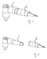
- Fig. 1 shows a perspective view of a hand-held device for local piercing of a human or an animal skin, in which a drive module 1 and a needle module 2 are coupled.
- Fig. 2 shows a perspective view of the handset Fig. 1 , wherein the needle module 2 is decoupled from the drive module 1.
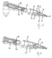
- Fig. 3 shows a perspective view of the handset after Fig. 2 in elevation in decoupled state.
- the needle module 2 has a proximal section 3, which may also be referred to as a coupling section independently of the specific embodiment, and a distal section 4, which may also be referred to as a needle receiving section regardless of the specific embodiment and in which a needle opening 5 is formed, through which a needle element 6 can be extended and retracted.
- the needle element 6, which may be formed with one or more needles, is in turn in one Needle shaft 7 is received, which forms a needle device 8 with the needle element 6.
- the needle device 8 is guided by means of a membrane 9.
- the membrane 9 is made of an elastic material and holds the needle device 8 in Fig. 3 shown decoupled state in a starting position.
- a functional element 10 designed as a stop element is formed on the proximal section 3.
- the functional element 10 cooperates with the coupling of the needle module 2 to the drive module 1 with an actuating element 11, which in the bottom of the Fig. 4 . 6 and 7 becomes clearer.
- the actuating element 11 is formed in the illustrated embodiment as a cylindrical sleeve which is slidably mounted in a housing portion 12.
- the displacement of the actuating element 11 from a first displacement position, the in Fig. 3 is shown and corresponds to an extended position, in a retracted position (see. Fig. 6 and 7 ) takes place against the bias of a spring element 13 when coupling the needle module 2 to the drive module. 1
- the actuating element 11 is functionally coupled to a needle connecting device 14 arranged in the housing section 12, such that upon insertion of the actuating element 11 the needle connecting device 14 is actuated so that the needle connecting device 14 moves into a coupling position which is in FIG Fig. 5 for the needle attachment device 14 is shown.
- a coupling position which is in FIG Fig. 5 for the needle attachment device 14 is shown.
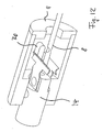
- the coupling position are according to Fig. 5 arranged as a clamping or fastening elements functional elements 15, 16 opposite arranged at a distance which allows the needle shaft 7 to couple thereto, such that the functional elements 15, 16 engage positively in a recess 17 on the needle shaft 7, which in particular Fig. 7 you can see.
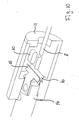
- the functional elements 15, 16 of the needle attachment device 14 arrive at the insertion of the actuating element 11 in the process of coupling the needle module 2 in the in Fig. 5 shown coupling position by wedge-shaped plunger 18, which are fixedly connected to the actuating element 11, are moved back, which is particularly in Fig. 6 you can see.
- a retaining pin 19 engages in a bore 20 in the proximal portion 3 of the needle module, whereby the needle module 2 is fixed to the drive module 1.
- the proximal portion 3 can be elastically deformed by the user by finger force, so that the bore 20 is released from the retaining pin 19, which enables the removal of the needle module 2.
- the actuator driven by the spring element 13, again in the in Fig. 3 shown position back.
- the wedge-shaped plungers 18 then push apart the functional elements 15, 16 of the needle attachment device 14, so that the needle device 8 can be released from the needle attachment device 14.
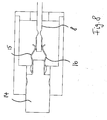
- Fig. 8 shows an enlarged detail view when coupling the needle device 8 to the needle attachment device 14th
- Fig. 9 shows an enlarged view of the Nadelan gleich adopted 14 with coupled needle device. 8
- Fig. 10 shows a perspective view with Nadelan gleich issued 14 and actuating element 11 according to a further embodiment. Unlike the embodiment in the Fig. 3, 4 . 6 and 7 the functional elements 15, 16 of the needle attachment device 14 are pushed apart by means of a projection 30, which in turn is arranged on the actuating element 11.
- Fig. 11 shows a perspective view of the arrangement Fig. 10 in the coupled state.
- Fig. 12 shows a perspective view of the arrangement Fig. 10 wherein the needle attachment device 14 is in an uncoupling or decoupling position.
- the projection 30 presses apart the functional elements 15, 16 here.
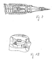
- Fig. 13 shows a perspective view of a portion of the drive module 1.
- An upper magnet 40 is in one Housing cover 2 inserted.
- a lower magnet 41 is arranged in a flywheel 43.
- the two magnets, 40, 41 are aligned so that at the in Fig. 13 shown opposite flywheel position opposite magnetic poles. If the electric motor of the drive module 1 remains in a different position, the two magnets 40, 41 generate a torque sufficient to cause the flywheel in the de-energized state in the in Fig. 13 to rotate shown position, whereby the needle element 6 is retracted. Thus, there is no risk of injury in the off state of the drive module. 1
- Fig. 14 and 15 show perspective views of a hand-held device, in which the needle module 2 is designed in several parts.
- the proximal portion 3 is separable from the distal portion 4.
- the proximal portion 4 can first be coupled, whereby the actuating element 11 is actuated (see. Fig. 14 ). Subsequently, the distal portion 4 is attached to the needle device 8 (see. Fig. 15 ).
- proximal portion 3 of the needle module 2 on the drive module 1 occupy two locking positions, such that the actuating element 11 of the drive module 1 at the same time assumes the first displacement position when the proximal portion 3 assumes the first detent position, and that the associated actuator 11 of the drive module at the same time assumes the second displacement position when the proximal portion 3 occupies the second detent position.
- the needle attachment device 8 is brought into the coupling / uncoupling position when the proximal portion 3 of the needle module 2 is in the second or first detent position.
- the distal section 4 of the needle module can be pulled off or connected to the proximal section 3 when the proximal section 3 assumes the first latching position.
- the distal portion 4 can be changed while the proximal portion 3 of the needle module 2 remains connected to the drive module 1.
Landscapes
- Health & Medical Sciences (AREA)
- Engineering & Computer Science (AREA)
- Dermatology (AREA)
- Medical Informatics (AREA)
- Anesthesiology (AREA)
- Biomedical Technology (AREA)
- Heart & Thoracic Surgery (AREA)
- Hematology (AREA)
- Life Sciences & Earth Sciences (AREA)
- Animal Behavior & Ethology (AREA)
- General Health & Medical Sciences (AREA)
- Public Health (AREA)
- Veterinary Medicine (AREA)
- Virology (AREA)
- Infusion, Injection, And Reservoir Apparatuses (AREA)
Claims (16)
- Appareil à main pour le perçage local d'une peau humaine ou d'une peau animale, en particulier pour l'introduction d'une matière active, pour le tatouage ou pour l'application de fond de teint permanent, avec :u n module d'entraînement (1) qui est configuré de manière à réaliser un mouvement d'entraînement répétitif, etu n module à aiguille (2) qui présente un équipement à aiguille (8) et est configuré de manière à se coupler au module d'entraînement (1) de telle sorte que le mouvement d'entraînement répétitif puisse être couplé à l'équipement à aiguille (8) pour l'entrée et la sortie de ce dernier,étant donné que sont formés sur le module d'entraînement (1) un élément d'actionnement (11) décalable couplé fonctionnellement à un équipement de raccord d'aiguille (14) et sur le module à aiguille (2) un élément fonctionnel (10) affecté à l'élément d'actionnement (11), élément configurés de manière à décaler, à l'accouplement du module à aiguille (2) avec le module d'entraînement (1), l'élément d'actionnement (11) avec l'élément fonctionnel (10) correspondant d'une première position de décalage à une deuxième position de décalage, ce par quoi l'équipement de raccord d'aiguille (14) est amené à une position de couplage à laquelle l'équipement à aiguille (8) peut être couplé à l'équipement de raccord d'aiguille (14) pour fonctionner.
- Appareil à main selon la revendication 1, caractérisé en ce que l'élément d'actionnement (11) est configuré de manière à se déplacer de façon autonome de la deuxième à la première position de décalage au désaccouplement du module à aiguille (2) du module d'entraînement (1), ce par quoi l'équipement de raccord d'aiguille (14) est amené à une position de désaccouplement à laquelle l'équipement à aiguille (8) peut être désaccouplé de l'équipement de raccord d'aiguille (14).
- Appareil à main selon la revendication 1 ou 2, caractérisé en ce que le module d'entraînement (1) et le module à aiguille (2) sont configurés de manière à être en liaison de couplage crabotée.
- Appareil à main selon au moins l'une quelconque des revendications précédentes, caractérisé en ce que le module à aiguille (2) présente une section proximale (3) à laquelle est formé l'élément fonctionnel (10) correspondant et qui est configurée de manière à accoupler le module d'entraînement (1), et une section distale (4) reliée à ce dernier, section distale dans laquelle est formée un orifice à aiguille (5) à travers lequel un élément d'aiguille (6) de l'équipement à aiguille (8) peut être introduit et sorti.
- Appareil à main selon la revendication 4, caractérisé en ce que la section proximale (3) et la section distale (4) sont reliées de manière amovible l'une avec l'autre.
- Appareil à main selon la revendication 4 ou 5, caractérisé en ce que, à une position à laquelle le module à aiguille (2) est accouplé avec le module d'entraînement (1), la section proximale (3) est fixée au module d'entraînement (1).
- Appareil à main selon au moins l'une quelconque des revendications 4 ou 6, caractérisé en ce que, à l'accouplement du module à aiguille (2) avec le module d'entraînement (1), la section proximale (3) est guidée à un boîtier (12) du module d'entraînement (1).
- Appareil à main selon au moins l'une quelconque des revendications précédentes, caractérisé en ce que l'élément d'actionnement (11) est configuré de manière à se déplacer entre la première et la deuxième position de décalage dans le sens d'un mouvement d'accouplement accompli par le module à aiguille (2) à l'accouplement du module à aiguille (2) avec le module d'entraînement (1).
- Appareil à main selon au moins l'une quelconque des revendications précédentes, caractérisé en ce que l'élément d'actionnement (11) est logé dans une coulisse sur le module d'entraînement (1) configurée de manière à guider l'élément d'actionnement (11) à la transition de la première position de décalage à la deuxième position de décalage.
- Appareil à main selon au moins l'une quelconque des revendications précédentes, caractérisé en ce que l'équipement de raccord d'aiguille (14) est formé avec un mécanisme de raccordement mécanique pour l'équipement à aiguille (8).
- Appareil à main selon la revendication 10, caractérisé en ce que l'équipement de raccord d'aiguille (14) présente des éléments de serrage et de fixation (15, 16) affectés l'un à l'autre et décalables l'un par rapport à l'autre.
- Appareil à main selon au moins l'une quelconque des revendications précédentes, caractérisé en ce que l'équipement de raccord d'aiguille (14) est configuré de manière à s'accoupler rigidement à l'équipement à aiguille (8).
- Appareil à main selon au moins l'une quelconque des revendications précédentes, caractérisé en ce que l'équipement à aiguille (8) est logé dans le module à aiguille (2) dans un élément de guidage (9) qui maintient l'équipement à aiguille (8) à une position de départ à l'accouplement du module à aiguille (2) avec le module d'entraînement (1).
- Procédé pour l'accouplement d'un module à aiguille (2) avec un module d'entraînement (1) sur un appareil à main selon au moins l'une quelconque des revendications 1 à 13, le procédé comprenant les étapes suivantes :- mise à disposition d'un module d'entraînement (1) qui est configuré de manière à réaliser un mouvement d'entraînement répétitif,- mise à disposition d'un module à aiguille (2) qui présente un équipement à aiguille (8) et est configuré de manière à se coupler au module d'entraînement (1) de telle sorte que le mouvement d'entraînement répétitif puisse être couplé à l'équipement à aiguille (8) pour l'entrée et la sortie de ce dernier, et- accouplement du module à aiguille (2) au module d'entraînement (1) par décalage d'un élément d'actionnement (11) décalable et fonctionnellement couplé à un équipement de raccord d'aiguille (14) du module d'entraînement (1) au moyen d'un élément fonctionnel (10) du module à aiguille (2), affecté à l'élément d'actionnement (11), d'une première position de décalage à une deuxième position de décalage, ce par quoi l'équipement de raccord d'aiguille (14) est amené à une position de couplage, puis par couplage de l'équipement à aiguille (8) pour le fonctionnement à l'équipement de raccord d'aiguille (14).
- Module d'entraînement (1) pour un appareil à main selon au moins l'une quelconque des revendications 1 à 13, avec :- des moyens d'entraînement configurés de manière à réaliser un mouvement d'entraînement répétitif,- un équipement de raccord d'aiguille (14) et- un élément d'actionnement (11) décalable couplé fonctionnellement à l'équipement de raccord d'aiguille (14) et configuré de manière à décaler, à l'accouplement d'un module à aiguille (2) avec un élément fonctionnel (10) formé sur ce dernier et affecté à l'élément d'actionnement (11), ledit élément d'actionnement (11) d'une première position de décalage à une deuxième position de décalage, ce par quoi l'équipement de raccord d'aiguille (14) est amené à une position de couplage à laquelle un équipement à aiguille (8) que comprend le module à aiguille (2) peut être couplé à l'équipement de raccord d'aiguille (14) pour fonctionner.
- Module à aiguille (2) pour un appareil à main selon au moins l'une quelconque des revendications 1 à 13, avec :- un équipement à aiguille (8) et- un élément fonctionnel (10) qui est affecté à un élément d'actionnement (11) décalable d'un module d'entraînement (1) accouplable et est configuré de manière à ce que, à l'accouplement avec le module d'entraînement (1), l'élément d'actionnement (11) soit décalé d'une première position de décalage à une deuxième position de décalage, ce par quoi un équipement de raccord d'aiguille (14) que comprend le module d'entraînement (1) est amené à une position à laquelle l'équipement à aiguille (8) peut être couplé à l'équipement de raccord d'aiguille (14) pour fonctionner.
Priority Applications (4)
| Application Number | Priority Date | Filing Date | Title |
|---|---|---|---|
| EP08013836A EP2149388B1 (fr) | 2008-08-01 | 2008-08-01 | Appareil manuel destiné au perçage local d'une peau humaine ou animale, module d'entraînement, module d'aiguille et procédé d'accouplement |
| DE502008002529T DE502008002529D1 (de) | 2008-08-01 | 2008-08-01 | Handgerät zum lokalen Aufstechen einer menschlichen oder tierischen Haut, Antriebsmodul, Nadelmodul sowie Verfahren zum Ankoppeln |
| ES08013836T ES2361359T3 (es) | 2008-08-01 | 2008-08-01 | Aparato manual para el pinchado local de piel humana o animal, módulo de accionamiento, módulo de aguja así como procedimiento de acoplamiento. |
| US12/533,973 US8414531B2 (en) | 2008-08-01 | 2009-07-31 | Handheld device for the local puncturing of a human or an animal skin, drive unit, needle unit and method for coupling |
Applications Claiming Priority (1)
| Application Number | Priority Date | Filing Date | Title |
|---|---|---|---|
| EP08013836A EP2149388B1 (fr) | 2008-08-01 | 2008-08-01 | Appareil manuel destiné au perçage local d'une peau humaine ou animale, module d'entraînement, module d'aiguille et procédé d'accouplement |
Publications (2)
| Publication Number | Publication Date |
|---|---|
| EP2149388A1 EP2149388A1 (fr) | 2010-02-03 |
| EP2149388B1 true EP2149388B1 (fr) | 2011-02-02 |
Family
ID=40289297
Family Applications (1)
| Application Number | Title | Priority Date | Filing Date |
|---|---|---|---|
| EP08013836A Not-in-force EP2149388B1 (fr) | 2008-08-01 | 2008-08-01 | Appareil manuel destiné au perçage local d'une peau humaine ou animale, module d'entraînement, module d'aiguille et procédé d'accouplement |
Country Status (4)
| Country | Link |
|---|---|
| US (1) | US8414531B2 (fr) |
| EP (1) | EP2149388B1 (fr) |
| DE (1) | DE502008002529D1 (fr) |
| ES (1) | ES2361359T3 (fr) |
Cited By (1)
| Publication number | Priority date | Publication date | Assignee | Title |
|---|---|---|---|---|
| DE102014103586A1 (de) | 2013-03-15 | 2014-09-18 | Athanassios D. Pimpas | Tätowierungsvorrichtungshandgriff mit Vibrationsmechanismus |
Families Citing this family (32)
| Publication number | Priority date | Publication date | Assignee | Title |
|---|---|---|---|---|
| ES2294951B1 (es) * | 2006-09-28 | 2008-12-01 | Kelian Gutierrez Ugarte | Maquina para peinar el cabello en forma de largos mechones de pelo entrelazado en rastas. |
| US8181554B2 (en) * | 2009-08-31 | 2012-05-22 | Mei-Chi-Na Hsinyen Co., Ltd. | Eyebrow embroidery machine |
| EP2392842B1 (fr) | 2010-06-02 | 2013-05-08 | Technische Universität Berlin | Dispositif de soupape pour la commande de l'écoulement d'un fluide à travers un canal de fluide, agencement et dispositif de soupape à voies multiples |
| PL2682146T3 (pl) * | 2012-07-05 | 2017-04-28 | Mt Derm Gmbh | Przyrząd ręczny do tatuowania lub nanoszenia makijażu permanentnego oraz moduł igłowy z regulowaną głębokością wkłuwania |
| CN203329182U (zh) * | 2013-07-06 | 2013-12-11 | 肖龙 | 纹身手柄隔离套 |
| US9427561B2 (en) | 2013-12-17 | 2016-08-30 | Mt.Derm Gmbh | Method for operating in a system for repetitive local puncturing of skin and system |
| US9393395B2 (en) | 2014-01-21 | 2016-07-19 | Michael Chen | Tattoo machine |
| ES2753302T3 (es) * | 2014-06-12 | 2020-04-08 | Mt Derm Gmbh | Aparato manual para la punción repetida de una piel humana o animal |
| USD746455S1 (en) * | 2014-12-09 | 2015-12-29 | Kingpin Tattoo Supply, Inc. | Tattoo needle cartridge |
| USD745152S1 (en) * | 2014-12-09 | 2015-12-08 | Kingpin Tattoo Supply, Inc. | Tattoo needle cartridge |
| ES2780876T3 (es) | 2015-03-06 | 2020-08-27 | Mt Derm Gmbh | Herramienta para la perforación de piel para la perforación local de una piel humana o animal y aparato de mano |
| CN104784044B (zh) * | 2015-05-12 | 2017-03-01 | 京东方科技集团股份有限公司 | 一种针灸装置 |
| KR20180084759A (ko) * | 2015-09-27 | 2018-07-25 | 폴리카 인코포레이티드 | 니들링 장치 및 약물 도포기 |
| WO2017178070A1 (fr) | 2016-04-15 | 2017-10-19 | Ink Machines Sweden Ab | Procédé et système de commande de machine de tatouage |
| WO2017178069A1 (fr) | 2016-04-15 | 2017-10-19 | Ink Machines Sweden Ab | Cartouche d'aiguille de tatouage jetable |
| US11260209B2 (en) | 2016-08-24 | 2022-03-01 | Fk Irons Inc. | Pen style microneedling machine apparatus |
| US10744312B2 (en) * | 2016-08-24 | 2020-08-18 | Fk Irons Inc. | Tattoo machine grip apparatus |
| AT518780B1 (de) * | 2016-10-13 | 2018-01-15 | Blackgold - Highend Tätowiersysteme Og | Handgerät zum Tätowieren |
| FR3065881B1 (fr) * | 2017-05-03 | 2022-01-28 | Trinitro | Systeme de bridage et de guidage d'un faisceau d'aiguilles sur un tube de tatouage |
| USD910175S1 (en) * | 2018-07-16 | 2021-02-09 | Mt.Derm Gmbh | Tattoo machine |
| US11400268B2 (en) | 2018-10-11 | 2022-08-02 | Fk Irons Inc. | Electromagnetically driven tattoo machine and system |
| EP3552658A1 (fr) * | 2018-12-10 | 2019-10-16 | MT Derm GmbH | Module d'entraînement et module d'aiguille pour un appareil portatif destiné à la ponction locale répétée d'une peau humaine ou d'une peau animale ainsi qu'appareil portatif |
| US11400425B2 (en) * | 2019-02-05 | 2022-08-02 | The Original Mixing Cartridge LLC | Tattoo ink mixing apparatus |
| CN112075009B (zh) | 2019-03-27 | 2024-09-10 | Fk艾恩斯公司 | 带电压控制器的纹身机可充电电池单元 |
| EP3753601B1 (fr) | 2019-06-21 | 2024-09-18 | Samia Trigo Arbache | Améliorations d'aiguille pour l'administration de médicaments à l'aide de machines de tatouage |
| USD920514S1 (en) * | 2019-09-12 | 2021-05-25 | Mt.Derm Gmbh | Handpiece of a tatoo machine |
| US20220257918A1 (en) | 2021-02-12 | 2022-08-18 | Fk Irons Inc. | Adapter Device For Tattoo Machine |
| EP4260897A1 (fr) * | 2022-04-14 | 2023-10-18 | MT.DERM GmbH | Dispositif d'entrainement pour un appareil portatif permettant d'inciser localement une peau et appareil portatif |
| USD1036669S1 (en) * | 2023-02-14 | 2024-07-23 | ProCell Therapies, LLC | Micro-channeling device |
| USD1024328S1 (en) | 2023-02-14 | 2024-04-23 | Pro Cell Therapies, LLC | Micro-needle tip assembly |
| USD1042823S1 (en) | 2023-02-14 | 2024-09-17 | Pro Cell Therapies, LLC | Needle tip connector |
| US12053608B1 (en) | 2023-02-14 | 2024-08-06 | ProCell Therapies, LLC | Micro-needling array treatment assembly |
Family Cites Families (13)
| Publication number | Priority date | Publication date | Assignee | Title |
|---|---|---|---|---|
| US5279552A (en) * | 1993-01-11 | 1994-01-18 | Anton Magnet | Intradermal injection device |
| US5472449A (en) * | 1993-07-26 | 1995-12-05 | Chou; Kuei C. | Permanent pigment applicator having a detachable needle coupler |
| US5471102A (en) * | 1994-05-09 | 1995-11-28 | Becker; Gregory R. | Reciprocating shaft device |
| DE19836376A1 (de) * | 1998-08-11 | 2000-02-17 | Kowitz Klaus Dieter | Vorrichtung zum Aufbringen von Permanent-Make-up |
| US6689095B1 (en) * | 1999-04-22 | 2004-02-10 | Gilbert Garitano | Needleless permanent makeup and tattoo device |
| DE19945334C2 (de) * | 1999-09-22 | 2002-07-18 | Matthias Schmitt | Nadelstichgerät zum Tätowieren einer Hautpartie |
| DE29919199U1 (de) * | 1999-10-22 | 2000-01-20 | MediUm-TECH GmbH, 12681 Berlin | Tattoo- und/oder Permanent-Make-up-Farben-Handgerät |
| KR100444139B1 (ko) * | 2002-04-10 | 2004-08-11 | 이상호 | 문신기구 |
| US7695486B2 (en) * | 2002-10-02 | 2010-04-13 | Linda Dixon | Intradermal color introducing needle device, and apparatus and method involving the same |
| DE502004002831D1 (de) * | 2004-07-21 | 2007-03-22 | Medium Tech Medizingeraete Gmb | Vorrichtung zum lokalen Aufstechen einer Haut |
| ES2334932T3 (es) * | 2006-07-25 | 2010-03-17 | Mt Derm Gmbh | Aparato de mano para el pinchado local repetido de la piel para la aplicacion de una sustancia activa liquida. |
| KR100789398B1 (ko) * | 2006-08-11 | 2007-12-28 | 봄텍전자 주식회사 | 문신장치 |
| US7380480B1 (en) * | 2007-02-23 | 2008-06-03 | Cheng-Kun Chen | Safety needle device for tattooing body and eyebrows |
-
2008
- 2008-08-01 DE DE502008002529T patent/DE502008002529D1/de active Active
- 2008-08-01 ES ES08013836T patent/ES2361359T3/es active Active
- 2008-08-01 EP EP08013836A patent/EP2149388B1/fr not_active Not-in-force
-
2009
- 2009-07-31 US US12/533,973 patent/US8414531B2/en not_active Expired - Fee Related
Cited By (1)
| Publication number | Priority date | Publication date | Assignee | Title |
|---|---|---|---|---|
| DE102014103586A1 (de) | 2013-03-15 | 2014-09-18 | Athanassios D. Pimpas | Tätowierungsvorrichtungshandgriff mit Vibrationsmechanismus |
Also Published As
| Publication number | Publication date |
|---|---|
| US20100036317A1 (en) | 2010-02-11 |
| US8414531B2 (en) | 2013-04-09 |
| ES2361359T3 (es) | 2011-06-16 |
| DE502008002529D1 (de) | 2011-03-17 |
| EP2149388A1 (fr) | 2010-02-03 |
Similar Documents
| Publication | Publication Date | Title |
|---|---|---|
| EP2149388B1 (fr) | Appareil manuel destiné au perçage local d'une peau humaine ou animale, module d'entraînement, module d'aiguille et procédé d'accouplement | |
| EP1958659B1 (fr) | Module d'entraînement pour un dispositif de perçage local d'une peau humaine ou animale et appareil manuel | |
| EP2376143B1 (fr) | Système d'insertion et dispositif d'insertion | |
| EP1384438B1 (fr) | Système de prélèvement du sang | |
| EP1618915B1 (fr) | Dispositif pour la ponction de la peau | |
| EP1383560B2 (fr) | Dispositif de perfusion | |
| EP1970084B1 (fr) | Dispositif d'insertion pour une tête d'insertion, en particulier pour un ensemble d'infusion | |
| EP1884191B1 (fr) | Système a piquer la peau | |
| DE68902781T2 (de) | Sicherheits-wegwerfspritze. | |
| DE68923622T2 (de) | Spritze zur einmaligen verwendung. | |
| DE60318936T2 (de) | Nadelschutzvorrichtung für eine spritze sowie injektionsvorrichtung bestehend aus einer spritze und dieser schutzvorrichtung | |
| EP2682146B1 (fr) | Appareil manuel pour appliquer tatouage ou maquillage permanent et module d'aiguille avec moyen d'ajuster profondeur de pénétration | |
| EP1032445B1 (fr) | Procede et dispositif de commande de la profondeur de penetration d'une aiguille pour injection | |
| EP3363492B1 (fr) | Module d'aiguilles pour un dispositif commandé par entraînement destiné au perçage répété d'une peau humaine ou animale et appareil manuel | |
| WO2018018165A1 (fr) | Capuchon externe doté d'un élément de retrait de protège-aiguille et procédé de montage d'un dispositif d'injection | |
| DE10103287A1 (de) | Verfahren zur Rekonstitution einer Injektionsflüssigkeit und Injektionsgerät zur Durchführung eines solchen Verfahrens | |
| WO2013016832A1 (fr) | Système de sécurité pour dispositifs d'injection | |
| EP3741287B1 (fr) | Coupleur d'endoscope pour une caméra et procédé de couplage et de découplage d'un endoscope doté d'une caméra au moyen d'un coupleur d'endoscope ainsi que caméra pourvue de coupleur d'endoscope | |
| DE102011120366A1 (de) | Vorrichtung zum repetierenden Einbringen von Stoffen in die Haut | |
| EP0750475A1 (fr) | Dispositif pour la mise en place controlee d'un trocart ou d'une canule de ponction | |
| DE102006048180A1 (de) | Injektionsvorrichtung mit einer Auslösesperre bei nicht eingelegtem Produktbehältnis | |
| WO2001043811A1 (fr) | Seringue pour implant | |
| EP2903494B1 (fr) | Système d'endoscopie et de biopsie à usage unique | |
| EP3752227B1 (fr) | Mécanisme de connexion pour module d'extension | |
| WO2015070888A1 (fr) | Unité de prélèvement d'échantillon, dispositif de prélèvement d'échantillon et procédé de prélèvement d'un échantillon |
Legal Events
| Date | Code | Title | Description |
|---|---|---|---|
| PUAI | Public reference made under article 153(3) epc to a published international application that has entered the european phase |
Free format text: ORIGINAL CODE: 0009012 |
|
| 17P | Request for examination filed |
Effective date: 20090311 |
|
| AK | Designated contracting states |
Kind code of ref document: A1 Designated state(s): AT BE BG CH CY CZ DE DK EE ES FI FR GB GR HR HU IE IS IT LI LT LU LV MC MT NL NO PL PT RO SE SI SK TR |
|
| AX | Request for extension of the european patent |
Extension state: AL BA MK RS |
|
| GRAP | Despatch of communication of intention to grant a patent |
Free format text: ORIGINAL CODE: EPIDOSNIGR1 |
|
| AKX | Designation fees paid |
Designated state(s): DE ES FR GB IT NL |
|
| GRAS | Grant fee paid |
Free format text: ORIGINAL CODE: EPIDOSNIGR3 |
|
| GRAA | (expected) grant |
Free format text: ORIGINAL CODE: 0009210 |
|
| AK | Designated contracting states |
Kind code of ref document: B1 Designated state(s): DE ES FR GB IT NL |
|
| REG | Reference to a national code |
Ref country code: GB Ref legal event code: FG4D Free format text: NOT ENGLISH |
|
| REF | Corresponds to: |
Ref document number: 502008002529 Country of ref document: DE Date of ref document: 20110317 Kind code of ref document: P |
|
| REG | Reference to a national code |
Ref country code: DE Ref legal event code: R096 Ref document number: 502008002529 Country of ref document: DE Effective date: 20110317 |
|
| REG | Reference to a national code |
Ref country code: NL Ref legal event code: T3 |
|
| REG | Reference to a national code |
Ref country code: ES Ref legal event code: FG2A Ref document number: 2361359 Country of ref document: ES Kind code of ref document: T3 Effective date: 20110616 |
|
| PLBE | No opposition filed within time limit |
Free format text: ORIGINAL CODE: 0009261 |
|
| STAA | Information on the status of an ep patent application or granted ep patent |
Free format text: STATUS: NO OPPOSITION FILED WITHIN TIME LIMIT |
|
| 26N | No opposition filed |
Effective date: 20111103 |
|
| REG | Reference to a national code |
Ref country code: DE Ref legal event code: R097 Ref document number: 502008002529 Country of ref document: DE Effective date: 20111103 |
|
| REG | Reference to a national code |
Ref country code: FR Ref legal event code: PLFP Year of fee payment: 9 |
|
| REG | Reference to a national code |
Ref country code: FR Ref legal event code: PLFP Year of fee payment: 10 |
|
| PGFP | Annual fee paid to national office [announced via postgrant information from national office to epo] |
Ref country code: NL Payment date: 20170728 Year of fee payment: 10 |
|
| PGFP | Annual fee paid to national office [announced via postgrant information from national office to epo] |
Ref country code: ES Payment date: 20170901 Year of fee payment: 10 Ref country code: FR Payment date: 20170728 Year of fee payment: 10 Ref country code: DE Payment date: 20170902 Year of fee payment: 10 Ref country code: GB Payment date: 20170726 Year of fee payment: 10 Ref country code: IT Payment date: 20170824 Year of fee payment: 10 |
|
| REG | Reference to a national code |
Ref country code: DE Ref legal event code: R119 Ref document number: 502008002529 Country of ref document: DE |
|
| REG | Reference to a national code |
Ref country code: NL Ref legal event code: MM Effective date: 20180901 |
|
| GBPC | Gb: european patent ceased through non-payment of renewal fee |
Effective date: 20180801 |
|
| PG25 | Lapsed in a contracting state [announced via postgrant information from national office to epo] |
Ref country code: NL Free format text: LAPSE BECAUSE OF NON-PAYMENT OF DUE FEES Effective date: 20180901 |
|
| PG25 | Lapsed in a contracting state [announced via postgrant information from national office to epo] |
Ref country code: DE Free format text: LAPSE BECAUSE OF NON-PAYMENT OF DUE FEES Effective date: 20190301 Ref country code: IT Free format text: LAPSE BECAUSE OF NON-PAYMENT OF DUE FEES Effective date: 20180801 |
|
| PG25 | Lapsed in a contracting state [announced via postgrant information from national office to epo] |
Ref country code: FR Free format text: LAPSE BECAUSE OF NON-PAYMENT OF DUE FEES Effective date: 20180831 |
|
| REG | Reference to a national code |
Ref country code: ES Ref legal event code: FD2A Effective date: 20190918 |
|
| PG25 | Lapsed in a contracting state [announced via postgrant information from national office to epo] |
Ref country code: ES Free format text: LAPSE BECAUSE OF NON-PAYMENT OF DUE FEES Effective date: 20180802 Ref country code: GB Free format text: LAPSE BECAUSE OF NON-PAYMENT OF DUE FEES Effective date: 20180801 |
|
| REG | Reference to a national code |
Ref country code: DE Ref legal event code: R081 Ref document number: 502008002529 Country of ref document: DE Owner name: TECHNISCHE UNIVERSITAET BERLIN, DE Free format text: FORMER OWNERS: MT DERM GMBH, 14167 BERLIN, DE; TECHNISCHE UNIVERSITAET BERLIN, 10623 BERLIN, DE Ref country code: DE Ref legal event code: R081 Ref document number: 502008002529 Country of ref document: DE Owner name: MT.DERM GMBH, DE Free format text: FORMER OWNERS: MT DERM GMBH, 14167 BERLIN, DE; TECHNISCHE UNIVERSITAET BERLIN, 10623 BERLIN, DE |