EP2148802B1 - Binäres einstellverfahren für die winkelposition der fläche eines motorfahrzeugrades - Google Patents
Binäres einstellverfahren für die winkelposition der fläche eines motorfahrzeugrades Download PDFInfo
- Publication number
- EP2148802B1 EP2148802B1 EP08805581A EP08805581A EP2148802B1 EP 2148802 B1 EP2148802 B1 EP 2148802B1 EP 08805581 A EP08805581 A EP 08805581A EP 08805581 A EP08805581 A EP 08805581A EP 2148802 B1 EP2148802 B1 EP 2148802B1
- Authority
- EP
- European Patent Office
- Prior art keywords
- wheel
- angular position
- plane
- adjustment method
- rolling
- Prior art date
- Legal status (The legal status is an assumption and is not a legal conclusion. Google has not performed a legal analysis and makes no representation as to the accuracy of the status listed.)
- Not-in-force
Links
Images
Classifications
-
- B—PERFORMING OPERATIONS; TRANSPORTING
- B62—LAND VEHICLES FOR TRAVELLING OTHERWISE THAN ON RAILS
- B62D—MOTOR VEHICLES; TRAILERS
- B62D17/00—Means on vehicles for adjusting camber, castor, or toe-in
-
- B—PERFORMING OPERATIONS; TRANSPORTING
- B60—VEHICLES IN GENERAL
- B60G—VEHICLE SUSPENSION ARRANGEMENTS
- B60G7/00—Pivoted suspension arms; Accessories thereof
- B60G7/006—Attaching arms to sprung or unsprung part of vehicle, characterised by comprising attachment means controlled by an external actuator, e.g. a fluid or electrical motor
-
- B—PERFORMING OPERATIONS; TRANSPORTING
- B60—VEHICLES IN GENERAL
- B60G—VEHICLE SUSPENSION ARRANGEMENTS
- B60G2200/00—Indexing codes relating to suspension types
- B60G2200/40—Indexing codes relating to the wheels in the suspensions
- B60G2200/462—Toe-in/out
- B60G2200/4622—Alignment adjustment
-
- B—PERFORMING OPERATIONS; TRANSPORTING
- B60—VEHICLES IN GENERAL
- B60G—VEHICLE SUSPENSION ARRANGEMENTS
- B60G2600/00—Indexing codes relating to particular elements, systems or processes used on suspension systems or suspension control systems
- B60G2600/02—Retarders, delaying means, dead zones, threshold values, cut-off frequency, timer interruption
Definitions
- the invention relates to a method for adjusting the angular position of rolling the plane of a wheel of a motor vehicle, and a wheel assembly of a motor vehicle in which said method can be implemented.
- the invention applies in particular to the adjustment of the angular position of rolling of the plane of a non-steered wheel, and a mounting of the rear wheel of a motor vehicle on an axle.
- the clamp angle is defined as the angle separating, in a horizontal plane parallel to the ground, the plane of the wheel of the median plane of the vehicle. When the front of the wheel moves inwardly or outwardly respectively, it is referred to as a clamp, respectively an opening.
- the camber angle is the angle of the plane of the wheel with the vertical axis, the camber being positive if the wheel leans towards the outside of the vehicle.
- Methods are also known for dynamically adjusting the angular position of rolling of the wheel plane, in which said adjustment is slaved to rolling conditions, especially in view of continuously adjusting said angular position as a function of the dynamic driving situation. .
- the document GB-2,373,228 discloses a truck axle on which the hunting angle can be adjusted according to the direction of travel of said truck.
- the axle comprises a wheel carrier mounted on a support by means of a first pivot, the carrier being mounted on the axle shaft by means of a second pivot.
- the carrier includes air springs for pivoting said carrier between two operational directions. A positive hunting angle is obtained when the truck moves forward, a negative hunting angle being obtained when said truck moves backwards.
- the document EP-1,145,936 discloses a wheel alignment adjustment device of a motor vehicle which comprises at least one pair of support members which are exactly or approximately adjacent and whose angular position can be actively adjusted during the movement of said vehicle, so that the angular adjustment is automatically adjusted by means of the alignment of the wheels in the event of a critical situation such as braking and / or steering with a large lateral force and / or rotation.
- the aim of the invention is to propose a method for adjusting the angular position of rolling the plane of a motor vehicle wheel which makes it possible to improve the energy efficiency and safety of the dynamic behavior of the vehicle, the implementation of said method being particularly simple both mechanically and in relation to the specific validation procedures for the functions involved in the dynamic behavior of said vehicle.
- the invention proposes a method for adjusting the angular position of rolling the plane of a motor vehicle wheel, wherein the wheel is mounted on said vehicle so that the plane of said wheel may have a static angular position and a safety angular position, said method providing for maintaining the plane of the wheel in static angular position during the rolling of said wheel and, in case of detection of at least one critical rolling parameter, of moving the wheel plane to a safety angular position for a predetermined period of time before returning said wheel plane to a static angular position.
- the invention proposes a wheel assembly of a motor vehicle by means of a wheel carrier, said wheel carrier being associated with said vehicle via at least one pivot so that the plane of the wheel may have a first substantially zero gripper angle and a second non-zero gripper angle, said assembly further comprising a binary actuator for moving the wheel carrier in each of the gripper angles of the wheel plane, said actuator comprising a control device which is connected to a system for determining at least one rolling parameter, said control device being arranged to adjust the clamp angle by implementing such a method.
- the invention relates to a method for adjusting the angular position of the plane of a motor vehicle wheel, in particular a non-steered rear wheel.
- the method can be implemented on each of the wheels of an axle.
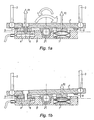
- the wheel is mounted so that the plane of the wheel can have two angular positions, respectively called static angular position ( figure 1a ) and angular safety position ( figure 1b ).
- the angular position of rolling is selected from the angle of clamp, camber angle or a combination of these two angles.
- the static angular position may correspond to a clamp angle and / or a substantially zero camber angle.
- the static angular position corresponds to 0 ° camber and camber angles
- the angular safety position corresponding to a clamp angle of less than 0.5 °, in particular of 0.35 °, and to a zero camber angle.
- the angular displacement of the wheel plane being less than 0.5 °, it is objectively not noticeable by the driver.
- the clamp angle of the safety angular position may be of the order of 1 °, or less.
- the wheel is rotatably mounted by means of a wheel carrier (not shown).
- the wheel carrier is associated with the vehicle via a plate 1 carrying a central pivot 2 for the arrangement of the wheel plane in the two angular positions by tilting said plate relative to said vehicle.
- the end of a suspension arm 3 is pivotally mounted on each of the ends of the plate 1, the other end of said arms being secured to the wheel carrier to transmit the tilting of the plate 1 to said wheel carrier.
- the arms 3 are spaced longitudinally so as to arrange the wheel plane according to two different gripper angles, in particular a substantially zero clamp angle and a non-zero clamp angle.
- an axle may be provided comprising a cross member on each end of which a wheel is mounted according to the invention.
- this latter embodiment can be used to counter the wheel plane when gripping the gripper.
- the wheel assembly further includes a binary actuator for moving the wheel carrier in each of the wheel plane clamp angles.
- the represented shareholder comprises a jack 4, for example hydroelastic, which is provided between a carrier 5 secured to the vehicle and the plate 1.
- the cylinder 4 comprises a member 6 for actuating the plate 1 tilting around the pivot 2, said member being associated in the vicinity of a first end of the plate 1, in particular between an arm 3 and the pivot 2.
- the support can be secured to the vehicle body or a sub-frame to facilitate assembly of the vehicle and better filter the vibrations.
- the actuator further comprises, opposite the jack 4 relative to the pivot 2, a spring 7 which is mounted in load between the support 5 and the plate 1. Moreover, to define the tilting stroke of the plate 1 relative to the support 5, said plate comprises abutments 8, 9 of contact with the support 5 in a tilting position, respectively.
- the cylinder when the cylinder is pressurized, it exerts a force F 1 which is greater than the force F 2 exerted by the spring 7, so as to tilt the plate 1 to dispose substantially longitudinally ( figure 1a ) with a stop 8 bearing on the support 5.
- this arrangement corresponds to a substantially zero clamp angle.
- the spring 7 in this position, is preloaded by bringing the plate 1 closer to the support 5.
- the force F 1 becomes less than the force F 2 so as to induce the tilting of the plate 1 in the second position with the other stop 9 bearing on the support 5 ( figure 1b ).
- This position corresponds to a non-zero clamp angle for the wheel plane.
- the plate 1 in the event of malfunction of the jack 4, the plate 1 is positioned in the position of the figure 1b , which corresponds to a non-zero clamp angle.
- the adjustment method according to the invention is described below which provides for maintaining the wheel plane in a static angular position during the rolling of the wheel and, in case of detection of at least one critical rolling parameter, to move the wheel. wheel plane in an angular safety position for a predetermined period of time before the return of said wheel plane in static angular position.
- the displacement of the wheel between its two angular positions is achieved by the binary actuator 4, 7 which has a state of static angular position and a state of angular position security.
- the actuator 4, 7 comprises a control device of the jack 4 which is connected to a system for determining at least one rolling parameter, said control device being arranged to adjust the clamp angle by setting implementation of the method.
- the determination system can use the existing sensors in the vehicle.
- the clamp angle is not controlled according to vehicle running conditions, which facilitates its implementation especially with regard to the validation constraints of the vehicle safety functions.
- the stable state of the actuator 4, 7 described corresponds to the angular safety position of the plane of the wheel, which makes it possible to secure the dynamic behavior of the vehicle in the event of failure of said actuator.
- the actuator 4, 7 can be arranged so that the time of setting security angular position is of the order of a tenth of a second, which allows rapid securing of the dynamic behavior. And, the return time in static position may be greater than the time of setting angular safety position, for example of the order of the second or even any tens of seconds. It is therefore possible to implement the control method with simple actuators and low power consumption.
- the period of time during which the safety position is maintained may be less than 10 seconds, in particular of the order of 5 seconds. Indeed, this duration is in most cases sufficient to stabilize the dynamic behavior of the vehicle.
- the critical rolling parameter may correspond to the exceeding of a threshold value for a rolling parameter of the vehicle, said parameter being able to be chosen from lateral acceleration, braking pressure, rotation speed of the steering wheel .
- the lateral acceleration threshold value is 0.7 g
- the braking pressure threshold value is 38 bar
- the steering wheel rotation speed threshold value is 500 ° / sec.
- the critical rolling parameter can be determined according to the speed of the vehicle and / or the intervention of a system for securing the dynamic behavior of the vehicle, such as ABS or ESP.
Landscapes
- Engineering & Computer Science (AREA)
- Mechanical Engineering (AREA)
- Chemical & Material Sciences (AREA)
- Combustion & Propulsion (AREA)
- Transportation (AREA)
- Vehicle Body Suspensions (AREA)
- Axle Suspensions And Sidecars For Cycles (AREA)
- Automatic Cycles, And Cycles In General (AREA)
- Body Structure For Vehicles (AREA)
- Length Measuring Devices By Optical Means (AREA)
- Control Of Multiple Motors (AREA)
- Testing Of Balance (AREA)
- Electric Propulsion And Braking For Vehicles (AREA)
- Arrangement Or Mounting Of Propulsion Units For Vehicles (AREA)
Claims (14)
- Verfahren zur Einstellung der Rollwinkelposition der Ebene eines Kraftfahrzeugrads, wobei das Rad so an dem Fahrzeug angebracht ist, dass die Ebene des Rads eine statische Winkelposition und eine Sicherheitswinkelposition aufweisen kann, wobei das Verfahren vorsieht, die Ebene des Rads beim Rollen des Rads in der statischen Winkelposition zu halten und bei Erfassung mindestens eines kritischen Rollparameters die Radebene für eine vorbestimmte Zeitdauer in eine Sicherheitswinkelposition zu verschieben, bevor die Radebene wieder in die statische Winkelposition zurückgeführt wird.
- Einstellverfahren nach Anspruch 1, dadurch gekennzeichnet, dass die Rollwinkelposition zwischen Radspurwinkel, Radsturzwinkel oder einer Kombination aus diesen beiden Winkeln ausgewählt wird.
- Einstellverfahren nach Anspruch 2, dadurch gekennzeichnet, dass die statische Winkelposition einem Radspurwinkel und/oder einem Radsturzwinkel von im Wesentlichen null entspricht.
- Einstellverfahren nach einem der Ansprüche 1 bis 3, dadurch gekennzeichnet, dass die Zeitdauern unter 10 Sekunden, insbesondere im Bereich von 5 Sekunden, liegen.
- Einstellverfahren nach einem der Ansprüche 1 bis 4, dadurch gekennzeichnet, dass der kritische Rollparameter dem Überschreiten eines Schwellwerts für einen Rollparameter des Fahrzeugs entspricht, wobei der Parameter zwischen Querbeschleunigung, Bremsdruck und Drehgeschwindigkeit des Lenkrads ausgewählt wird.
- Einstellverfahren nach einem der Ansprüche 1 bis 5, dadurch gekennzeichnet, dass die Verschiebung des Rads zwischen seinen beiden Winkelpositionen durch einen binären Aktuator (4, 7) durchgeführt wird, der einen Zustand zur Stellung in die statische Winkelposition und einen Zustand zur Stellung in die Sicherheitswinkelposition aufweist.
- Einstellverfahren nach Anspruch 6, dadurch gekennzeichnet, dass der stabile Zustand des Aktuators (4, 7) der Sicherheitswinkelposition der Radebene entspricht.
- Einstellverfahren nach Anspruch 6 oder 7, dadurch gekennzeichnet, dass die Zeit zur Stellung in die Sicherheitswinkelposition ca. eine Zehntelsekunde beträgt.
- Einstellverfahren nach einem der Ansprüche 1 bis 8, dadurch gekennzeichnet, dass die Zeit zur Rückführung der Radebene in die statische Position länger ist als die Zeit zur Stellung in die Sicherheitswinkelposition.
- Montage eines Kraftfahrzeugrads mittels eines Radhalters, wobei der Radhalter mittels mindestens eines Drehzapfens (2) so mit dem Fahrzeug verbunden ist, dass die Radebene einen ersten Radspurwinkel von im Wesentlichen null und einen zweiten Radspurwinkel von ungleich null aufweisen kann, wobei die Montage des Weiteren einen binären Aktuator (4, 7) zur Verschiebung des Halters in jeden der Spurwinkel der Radebene umfasst, wobei der Aktuator eine Steuervorrichtung umfasst, die mit einem System zur Bestimmung mindestens eines Rollparameters verbunden ist, wobei die Steuervorrichtung zur Einstellung des Spurwinkels durch Verwendung des Verfahrens nach einem der vorhergehenden Ansprüche angeordnet ist.
- Radmontage nach Anspruch 10, dadurch gekennzeichnet, dass der Radhalter mittels einer Grundplatte (1), die einen mittleren Drehzapfen (2) trägt, mit dem Fahrzeug verbunden ist.
- Radmontage nach Anspruch 11, dadurch gekennzeichnet, dass der binäre Aktuator Folgendes umfasst:- einen Zylinder (4), der zwischen einer Stütze (5) und der Grundplatte (1) vorgesehen ist, wobei der Zylinder ein Glied (6) zur Betätigung der Grundplatte (1) zum Kippen um den Drehzapfen (2) enthält; und- gegenüber dem Zylinder (4) bezüglich des Drehzapfens (2) eine Feder (7), die zwischen der Stütze (5) und der Grundplatte (1) gespannt angebracht ist.
- Radmontage nach Anspruch 12, dadurch gekennzeichnet, dass die Grundplatte (1) zwei Anschläge (8, 9) zum Kontakt mit der Stütze (5) in jeweils einer Kippposition aufweist.
- Radmontage nach Anspruch 12 oder 13, dadurch gekennzeichnet, dass die statische Winkelposition durch Aktivierung des Zylinders erhalten wird, wobei die Feder (7) in dieser Position vorbelastet ist, um die Sicherheitswinkelposition bei Deaktivierung des Zylinders (4) zu erhalten.
Applications Claiming Priority (2)
| Application Number | Priority Date | Filing Date | Title |
|---|---|---|---|
| FR0703665A FR2916412B1 (fr) | 2007-05-23 | 2007-05-23 | Procede de reglage binaire de la position angulaire du plan d'une roue de vehicule automobile. |
| PCT/FR2008/000685 WO2008155485A2 (fr) | 2007-05-23 | 2008-05-16 | Procédé de réglage binaire de la position angulaire du plan d'une roue de véhicule automobile |
Publications (2)
| Publication Number | Publication Date |
|---|---|
| EP2148802A2 EP2148802A2 (de) | 2010-02-03 |
| EP2148802B1 true EP2148802B1 (de) | 2011-02-23 |
Family
ID=38805748
Family Applications (1)
| Application Number | Title | Priority Date | Filing Date |
|---|---|---|---|
| EP08805581A Not-in-force EP2148802B1 (de) | 2007-05-23 | 2008-05-16 | Binäres einstellverfahren für die winkelposition der fläche eines motorfahrzeugrades |
Country Status (8)
| Country | Link |
|---|---|
| US (1) | US8645027B2 (de) |
| EP (1) | EP2148802B1 (de) |
| JP (1) | JP2010527833A (de) |
| CN (1) | CN101720291B (de) |
| AT (1) | ATE499268T1 (de) |
| DE (1) | DE602008005130D1 (de) |
| FR (1) | FR2916412B1 (de) |
| WO (1) | WO2008155485A2 (de) |
Families Citing this family (9)
| Publication number | Priority date | Publication date | Assignee | Title |
|---|---|---|---|---|
| FR2916413B1 (fr) * | 2007-05-23 | 2010-01-15 | Michelin Soc Tech | Montage de roue d'un vehicule automobile comprenant un actionneur binaire de reglage de la position angulaire du plan d'une roue. |
| FR2928581B1 (fr) * | 2008-03-17 | 2012-02-10 | Michelin Soc Tech | Ensemble routier comprenant un vehicule et un train de pneus |
| FR2941666B1 (fr) | 2009-02-03 | 2012-07-20 | Peugeot Citroen Automobiles Sa | Procede de controle du braquage des roues arriere d'un vehicule automobile. |
| FR2943417B1 (fr) | 2009-03-19 | 2011-06-10 | Michelin Soc Tech | Procede de determination d'un coefficient d'adherence d'une roue par mise en pince simultanee |
| JP2010228470A (ja) * | 2009-03-25 | 2010-10-14 | Equos Research Co Ltd | 車両用制御装置 |
| FR2947234B1 (fr) * | 2009-06-30 | 2011-07-15 | Michelin Soc Tech | Ensemble routier comprenant un vehicule et un train de pneus. |
| FR2961778A1 (fr) * | 2010-06-29 | 2011-12-30 | Michelin Soc Tech | Essieu suspendu pour vehicule automobile |
| DE102012206337B4 (de) * | 2012-04-18 | 2020-01-23 | Schaeffler Technologies AG & Co. KG | Vorrichtung einer Radaufhängung eines zweispurigen Fahrzeugs |
| US9821849B2 (en) * | 2015-12-04 | 2017-11-21 | Bosch Automotive Service Solutions Llc | Wheel alignment and toe angle adjustment system for a three-wheeled vehicle |
Family Cites Families (19)
| Publication number | Priority date | Publication date | Assignee | Title |
|---|---|---|---|---|
| GB2155869B (en) * | 1984-03-15 | 1987-06-24 | Honda Motor Co Ltd | Wheel alignment control system |
| JPH04129881A (ja) * | 1990-09-20 | 1992-04-30 | Mazda Motor Corp | 車両の後輪操舵装置 |
| JP2970163B2 (ja) * | 1991-12-27 | 1999-11-02 | 三菱自動車工業株式会社 | 車輪のキャンバ角制御装置 |
| KR0154036B1 (ko) * | 1993-08-06 | 1998-10-15 | 전성원 | 자동차 바퀴의 위치 보정장치 및 그 보정방법 |
| US5510988A (en) * | 1994-12-19 | 1996-04-23 | General Motors Corporation | Vehicle chassis control system |
| US5570289A (en) * | 1995-03-27 | 1996-10-29 | General Motors Corporation | Vehicle suspension control with wheel and body demand force phase determination |
| US5897130A (en) * | 1995-05-15 | 1999-04-27 | General Motors Corporation | Chassis control system for controlling a vehicle chassis system based on wheel speed data |
| DE10018532A1 (de) * | 2000-04-13 | 2001-10-18 | Continental Ag | Vorrichtung zur Spureinstellung an einem Fahrzeug |
| GB0106331D0 (en) * | 2001-03-15 | 2001-05-02 | Hendrickson Europ Ltd | Vehicle axle |
| DE10115217C1 (de) * | 2001-03-28 | 2002-08-14 | Bosch Gmbh Robert | Verfahren zum Bestimmen der Winkellage eines Fahrzeugs |
| AU2003231558A1 (en) * | 2002-06-19 | 2004-01-06 | Honda Giken Kogyo Kabushiki Kaisha | Device and method for measuring position of wheel inclination angle adjustment member, shaft-like work adjuster, and shaft-like work setting method |
| US20040024504A1 (en) * | 2002-08-05 | 2004-02-05 | Salib Albert Chenouda | System and method for operating a rollover control system during an elevated condition |
| JP2004122932A (ja) * | 2002-10-02 | 2004-04-22 | Nissan Motor Co Ltd | 車両用懸架装置 |
| JP4455340B2 (ja) * | 2002-12-11 | 2010-04-21 | ソシエテ ド テクノロジー ミシュラン | ホイール支持装置、サスペンションシステムおよびホイール支持装置を備えた車両 |
| US7210693B2 (en) * | 2004-06-16 | 2007-05-01 | Stempf Automotive Industries, Ltd | Dual axis bushing assembly and method for camber and caster adjustment |
| JP4523818B2 (ja) * | 2004-09-09 | 2010-08-11 | 株式会社ブリヂストン | 車輪姿勢角測定装置及び車輪姿勢角測定方法 |
| JP4867460B2 (ja) * | 2005-04-27 | 2012-02-01 | 株式会社エクォス・リサーチ | 制御装置 |
| JP2007008309A (ja) * | 2005-06-30 | 2007-01-18 | Nissan Motor Co Ltd | サスペンション装置 |
| JP2007112197A (ja) * | 2005-10-18 | 2007-05-10 | Nissan Motor Co Ltd | 車両用操舵装置 |
-
2007
- 2007-05-23 FR FR0703665A patent/FR2916412B1/fr not_active Expired - Fee Related
-
2008
- 2008-05-16 JP JP2010508875A patent/JP2010527833A/ja active Pending
- 2008-05-16 US US12/601,082 patent/US8645027B2/en not_active Expired - Fee Related
- 2008-05-16 WO PCT/FR2008/000685 patent/WO2008155485A2/fr not_active Ceased
- 2008-05-16 CN CN2008800171578A patent/CN101720291B/zh not_active Expired - Fee Related
- 2008-05-16 DE DE602008005130T patent/DE602008005130D1/de active Active
- 2008-05-16 EP EP08805581A patent/EP2148802B1/de not_active Not-in-force
- 2008-05-16 AT AT08805581T patent/ATE499268T1/de not_active IP Right Cessation
Also Published As
| Publication number | Publication date |
|---|---|
| WO2008155485A3 (fr) | 2009-02-19 |
| CN101720291A (zh) | 2010-06-02 |
| US20110040456A1 (en) | 2011-02-17 |
| ATE499268T1 (de) | 2011-03-15 |
| US8645027B2 (en) | 2014-02-04 |
| DE602008005130D1 (de) | 2011-04-07 |
| EP2148802A2 (de) | 2010-02-03 |
| FR2916412A1 (fr) | 2008-11-28 |
| WO2008155485A2 (fr) | 2008-12-24 |
| CN101720291B (zh) | 2012-09-05 |
| JP2010527833A (ja) | 2010-08-19 |
| FR2916412B1 (fr) | 2009-08-21 |
Similar Documents
| Publication | Publication Date | Title |
|---|---|---|
| EP2148802B1 (de) | Binäres einstellverfahren für die winkelposition der fläche eines motorfahrzeugrades | |
| EP1276656B1 (de) | Aufnahmevorrichtung eines rads und radaufhängung, die diese aufnahmevorrichtung enthält | |
| EP2150452B1 (de) | Einstellwerkzeug für motorfahrzeugräder mit einem binären aktuator zur einstellung der winkelposition der fläche eines rades | |
| EP3046780B1 (de) | Anordnung mit einem fahrgestell für ein fahrzeug mit variabler spur, z. b. ein landwirtschaftliches fahrzeug wie einen sprüher oder ein hohes reinigungsfahrzeug | |
| EP1247663A1 (de) | Fahrzeugaufhängung mit Sturzänderung | |
| EP0354113B1 (de) | Vorrichtung zur Lageregelung eines Kraftfahrzeuges | |
| WO2013079850A1 (fr) | Dispositif d'ajustement de l'angle de parallélisme des roues d'un véhicule | |
| FR2868359A1 (fr) | Suspension du type a jambe | |
| WO2005023569A1 (fr) | Train a pivot independant | |
| FR3071472B1 (fr) | Vehicule agricole avec correction de glissement par les roues arriere | |
| FR2961778A1 (fr) | Essieu suspendu pour vehicule automobile | |
| FR2931121A1 (fr) | Montage de roue d'un vehicule automobile au moyen d'un bras pliable entre deux configurations angulaires respectivement contrainte et stable | |
| FR2924393A1 (fr) | Procede et dispositif de reglage du train de roulement d'un vehicule automobile | |
| EP1996415B1 (de) | Fahrzeug mit einer aufhängungsvorrichtung mit variablem radsturz | |
| FR2910845A1 (fr) | Dispositif de commande du carrossage d'un vehicule. | |
| WO2005075237A1 (fr) | Dispositif de commande d'embrayage pour vehicule comprenant deux ressorts d'assistance | |
| EP3362304B1 (de) | Anordnung zur verbindung eines achsschenkels mit einem strukturelement eines kraftfahrzeugs | |
| EP1357014B1 (de) | Lenkungkompensationseinrichtung eines Kraftfahrzeugs | |
| FR2926492A1 (fr) | Sous ensemble de train roulant de vehicule | |
| WO2012175844A1 (fr) | Bras de suspension de vehicule | |
| EP3215377A1 (de) | Achsschenkel für eine kraftfahrzeugachse | |
| FR2950596A1 (fr) | Vehicule comportant une seule roue arriere a maniabilite amelioree et procede de pilotage d'un tel vehicule | |
| FR2913939A1 (fr) | Architecture d'actionnement du braquage d'une roue au moyen de deux biellettes | |
| WO2005075223A1 (fr) | Dispositif anti-roulis pour vehicule comprenant des moyens commandables pour rigidifier la liaison entre deux roues |
Legal Events
| Date | Code | Title | Description |
|---|---|---|---|
| PUAI | Public reference made under article 153(3) epc to a published international application that has entered the european phase |
Free format text: ORIGINAL CODE: 0009012 |
|
| 17P | Request for examination filed |
Effective date: 20091119 |
|
| AK | Designated contracting states |
Kind code of ref document: A2 Designated state(s): AT BE BG CH CY CZ DE DK EE ES FI FR GB GR HR HU IE IS IT LI LT LU LV MC MT NL NO PL PT RO SE SI SK TR |
|
| AX | Request for extension of the european patent |
Extension state: AL BA MK RS |
|
| 17Q | First examination report despatched |
Effective date: 20100407 |
|
| GRAP | Despatch of communication of intention to grant a patent |
Free format text: ORIGINAL CODE: EPIDOSNIGR1 |
|
| GRAS | Grant fee paid |
Free format text: ORIGINAL CODE: EPIDOSNIGR3 |
|
| GRAA | (expected) grant |
Free format text: ORIGINAL CODE: 0009210 |
|
| AK | Designated contracting states |
Kind code of ref document: B1 Designated state(s): AT BE BG CH CY CZ DE DK EE ES FI FR GB GR HR HU IE IS IT LI LT LU LV MC MT NL NO PL PT RO SE SI SK TR |
|
| REG | Reference to a national code |
Ref country code: GB Ref legal event code: FG4D Free format text: NOT ENGLISH |
|
| REG | Reference to a national code |
Ref country code: CH Ref legal event code: EP |
|
| REG | Reference to a national code |
Ref country code: IE Ref legal event code: FG4D Free format text: LANGUAGE OF EP DOCUMENT: FRENCH |
|
| REF | Corresponds to: |
Ref document number: 602008005130 Country of ref document: DE Date of ref document: 20110407 Kind code of ref document: P |
|
| REG | Reference to a national code |
Ref country code: DE Ref legal event code: R096 Ref document number: 602008005130 Country of ref document: DE Effective date: 20110407 |
|
| REG | Reference to a national code |
Ref country code: NL Ref legal event code: VDEP Effective date: 20110223 |
|
| LTIE | Lt: invalidation of european patent or patent extension |
Effective date: 20110223 |
|
| PG25 | Lapsed in a contracting state [announced via postgrant information from national office to epo] |
Ref country code: PT Free format text: LAPSE BECAUSE OF FAILURE TO SUBMIT A TRANSLATION OF THE DESCRIPTION OR TO PAY THE FEE WITHIN THE PRESCRIBED TIME-LIMIT Effective date: 20110623 Ref country code: HR Free format text: LAPSE BECAUSE OF FAILURE TO SUBMIT A TRANSLATION OF THE DESCRIPTION OR TO PAY THE FEE WITHIN THE PRESCRIBED TIME-LIMIT Effective date: 20110223 Ref country code: GR Free format text: LAPSE BECAUSE OF FAILURE TO SUBMIT A TRANSLATION OF THE DESCRIPTION OR TO PAY THE FEE WITHIN THE PRESCRIBED TIME-LIMIT Effective date: 20110524 Ref country code: LV Free format text: LAPSE BECAUSE OF FAILURE TO SUBMIT A TRANSLATION OF THE DESCRIPTION OR TO PAY THE FEE WITHIN THE PRESCRIBED TIME-LIMIT Effective date: 20110223 Ref country code: SE Free format text: LAPSE BECAUSE OF FAILURE TO SUBMIT A TRANSLATION OF THE DESCRIPTION OR TO PAY THE FEE WITHIN THE PRESCRIBED TIME-LIMIT Effective date: 20110223 Ref country code: ES Free format text: LAPSE BECAUSE OF FAILURE TO SUBMIT A TRANSLATION OF THE DESCRIPTION OR TO PAY THE FEE WITHIN THE PRESCRIBED TIME-LIMIT Effective date: 20110603 Ref country code: NO Free format text: LAPSE BECAUSE OF FAILURE TO SUBMIT A TRANSLATION OF THE DESCRIPTION OR TO PAY THE FEE WITHIN THE PRESCRIBED TIME-LIMIT Effective date: 20110523 Ref country code: LT Free format text: LAPSE BECAUSE OF FAILURE TO SUBMIT A TRANSLATION OF THE DESCRIPTION OR TO PAY THE FEE WITHIN THE PRESCRIBED TIME-LIMIT Effective date: 20110223 |
|
| PG25 | Lapsed in a contracting state [announced via postgrant information from national office to epo] |
Ref country code: AT Free format text: LAPSE BECAUSE OF FAILURE TO SUBMIT A TRANSLATION OF THE DESCRIPTION OR TO PAY THE FEE WITHIN THE PRESCRIBED TIME-LIMIT Effective date: 20110223 Ref country code: CY Free format text: LAPSE BECAUSE OF FAILURE TO SUBMIT A TRANSLATION OF THE DESCRIPTION OR TO PAY THE FEE WITHIN THE PRESCRIBED TIME-LIMIT Effective date: 20110223 Ref country code: BG Free format text: LAPSE BECAUSE OF FAILURE TO SUBMIT A TRANSLATION OF THE DESCRIPTION OR TO PAY THE FEE WITHIN THE PRESCRIBED TIME-LIMIT Effective date: 20110523 Ref country code: NL Free format text: LAPSE BECAUSE OF FAILURE TO SUBMIT A TRANSLATION OF THE DESCRIPTION OR TO PAY THE FEE WITHIN THE PRESCRIBED TIME-LIMIT Effective date: 20110223 Ref country code: FI Free format text: LAPSE BECAUSE OF FAILURE TO SUBMIT A TRANSLATION OF THE DESCRIPTION OR TO PAY THE FEE WITHIN THE PRESCRIBED TIME-LIMIT Effective date: 20110223 Ref country code: SI Free format text: LAPSE BECAUSE OF FAILURE TO SUBMIT A TRANSLATION OF THE DESCRIPTION OR TO PAY THE FEE WITHIN THE PRESCRIBED TIME-LIMIT Effective date: 20110223 |
|
| REG | Reference to a national code |
Ref country code: IE Ref legal event code: FD4D |
|
| PG25 | Lapsed in a contracting state [announced via postgrant information from national office to epo] |
Ref country code: EE Free format text: LAPSE BECAUSE OF FAILURE TO SUBMIT A TRANSLATION OF THE DESCRIPTION OR TO PAY THE FEE WITHIN THE PRESCRIBED TIME-LIMIT Effective date: 20110223 Ref country code: DK Free format text: LAPSE BECAUSE OF FAILURE TO SUBMIT A TRANSLATION OF THE DESCRIPTION OR TO PAY THE FEE WITHIN THE PRESCRIBED TIME-LIMIT Effective date: 20110223 Ref country code: IE Free format text: LAPSE BECAUSE OF FAILURE TO SUBMIT A TRANSLATION OF THE DESCRIPTION OR TO PAY THE FEE WITHIN THE PRESCRIBED TIME-LIMIT Effective date: 20110223 |
|
| BERE | Be: lapsed |
Owner name: SOC. DE TECHNOLOGIE MICHELIN Effective date: 20110531 Owner name: MICHELIN RECHERCHE ET TECHNIQUE S.A. Effective date: 20110531 |
|
| PG25 | Lapsed in a contracting state [announced via postgrant information from national office to epo] |
Ref country code: RO Free format text: LAPSE BECAUSE OF FAILURE TO SUBMIT A TRANSLATION OF THE DESCRIPTION OR TO PAY THE FEE WITHIN THE PRESCRIBED TIME-LIMIT Effective date: 20110223 Ref country code: CZ Free format text: LAPSE BECAUSE OF FAILURE TO SUBMIT A TRANSLATION OF THE DESCRIPTION OR TO PAY THE FEE WITHIN THE PRESCRIBED TIME-LIMIT Effective date: 20110223 Ref country code: SK Free format text: LAPSE BECAUSE OF FAILURE TO SUBMIT A TRANSLATION OF THE DESCRIPTION OR TO PAY THE FEE WITHIN THE PRESCRIBED TIME-LIMIT Effective date: 20110223 |
|
| PG25 | Lapsed in a contracting state [announced via postgrant information from national office to epo] |
Ref country code: MC Free format text: LAPSE BECAUSE OF NON-PAYMENT OF DUE FEES Effective date: 20110531 Ref country code: MT Free format text: LAPSE BECAUSE OF FAILURE TO SUBMIT A TRANSLATION OF THE DESCRIPTION OR TO PAY THE FEE WITHIN THE PRESCRIBED TIME-LIMIT Effective date: 20110223 |
|
| PLBE | No opposition filed within time limit |
Free format text: ORIGINAL CODE: 0009261 |
|
| STAA | Information on the status of an ep patent application or granted ep patent |
Free format text: STATUS: NO OPPOSITION FILED WITHIN TIME LIMIT |
|
| 26N | No opposition filed |
Effective date: 20111124 |
|
| PG25 | Lapsed in a contracting state [announced via postgrant information from national office to epo] |
Ref country code: PL Free format text: LAPSE BECAUSE OF FAILURE TO SUBMIT A TRANSLATION OF THE DESCRIPTION OR TO PAY THE FEE WITHIN THE PRESCRIBED TIME-LIMIT Effective date: 20110223 |
|
| REG | Reference to a national code |
Ref country code: DE Ref legal event code: R097 Ref document number: 602008005130 Country of ref document: DE Effective date: 20111124 |
|
| PG25 | Lapsed in a contracting state [announced via postgrant information from national office to epo] |
Ref country code: BE Free format text: LAPSE BECAUSE OF NON-PAYMENT OF DUE FEES Effective date: 20110531 |
|
| REG | Reference to a national code |
Ref country code: CH Ref legal event code: PL |
|
| GBPC | Gb: european patent ceased through non-payment of renewal fee |
Effective date: 20120516 |
|
| PG25 | Lapsed in a contracting state [announced via postgrant information from national office to epo] |
Ref country code: LI Free format text: LAPSE BECAUSE OF NON-PAYMENT OF DUE FEES Effective date: 20120531 Ref country code: CH Free format text: LAPSE BECAUSE OF NON-PAYMENT OF DUE FEES Effective date: 20120531 |
|
| PG25 | Lapsed in a contracting state [announced via postgrant information from national office to epo] |
Ref country code: GB Free format text: LAPSE BECAUSE OF NON-PAYMENT OF DUE FEES Effective date: 20120516 |
|
| PG25 | Lapsed in a contracting state [announced via postgrant information from national office to epo] |
Ref country code: LU Free format text: LAPSE BECAUSE OF NON-PAYMENT OF DUE FEES Effective date: 20110516 |
|
| PG25 | Lapsed in a contracting state [announced via postgrant information from national office to epo] |
Ref country code: IS Free format text: LAPSE BECAUSE OF FAILURE TO SUBMIT A TRANSLATION OF THE DESCRIPTION OR TO PAY THE FEE WITHIN THE PRESCRIBED TIME-LIMIT Effective date: 20110223 |
|
| PG25 | Lapsed in a contracting state [announced via postgrant information from national office to epo] |
Ref country code: TR Free format text: LAPSE BECAUSE OF FAILURE TO SUBMIT A TRANSLATION OF THE DESCRIPTION OR TO PAY THE FEE WITHIN THE PRESCRIBED TIME-LIMIT Effective date: 20110223 |
|
| PG25 | Lapsed in a contracting state [announced via postgrant information from national office to epo] |
Ref country code: HU Free format text: LAPSE BECAUSE OF FAILURE TO SUBMIT A TRANSLATION OF THE DESCRIPTION OR TO PAY THE FEE WITHIN THE PRESCRIBED TIME-LIMIT Effective date: 20110223 |
|
| REG | Reference to a national code |
Ref country code: FR Ref legal event code: PLFP Year of fee payment: 9 |
|
| REG | Reference to a national code |
Ref country code: FR Ref legal event code: PLFP Year of fee payment: 10 |
|
| REG | Reference to a national code |
Ref country code: FR Ref legal event code: PLFP Year of fee payment: 11 |
|
| PGFP | Annual fee paid to national office [announced via postgrant information from national office to epo] |
Ref country code: FR Payment date: 20200522 Year of fee payment: 13 Ref country code: DE Payment date: 20200520 Year of fee payment: 13 |
|
| PGFP | Annual fee paid to national office [announced via postgrant information from national office to epo] |
Ref country code: IT Payment date: 20200528 Year of fee payment: 13 |
|
| REG | Reference to a national code |
Ref country code: DE Ref legal event code: R119 Ref document number: 602008005130 Country of ref document: DE |
|
| PG25 | Lapsed in a contracting state [announced via postgrant information from national office to epo] |
Ref country code: DE Free format text: LAPSE BECAUSE OF NON-PAYMENT OF DUE FEES Effective date: 20211201 |
|
| PG25 | Lapsed in a contracting state [announced via postgrant information from national office to epo] |
Ref country code: FR Free format text: LAPSE BECAUSE OF NON-PAYMENT OF DUE FEES Effective date: 20210531 |
|
| PG25 | Lapsed in a contracting state [announced via postgrant information from national office to epo] |
Ref country code: IT Free format text: LAPSE BECAUSE OF NON-PAYMENT OF DUE FEES Effective date: 20200516 |
|
| PG25 | Lapsed in a contracting state [announced via postgrant information from national office to epo] |
Ref country code: IT Free format text: LAPSE BECAUSE OF NON-PAYMENT OF DUE FEES Effective date: 20210516 |