EP2148407A1 - Machine synchrone à aimants permanents - Google Patents
Machine synchrone à aimants permanents Download PDFInfo
- Publication number
- EP2148407A1 EP2148407A1 EP09009264A EP09009264A EP2148407A1 EP 2148407 A1 EP2148407 A1 EP 2148407A1 EP 09009264 A EP09009264 A EP 09009264A EP 09009264 A EP09009264 A EP 09009264A EP 2148407 A1 EP2148407 A1 EP 2148407A1
- Authority
- EP
- European Patent Office
- Prior art keywords
- permanent magnets
- synchronous machine
- permanent
- magnet synchronous
- permanent magnet
- Prior art date
- Legal status (The legal status is an assumption and is not a legal conclusion. Google has not performed a legal analysis and makes no representation as to the accuracy of the status listed.)
- Withdrawn
Links
Images
Classifications
-
- H—ELECTRICITY
- H02—GENERATION; CONVERSION OR DISTRIBUTION OF ELECTRIC POWER
- H02K—DYNAMO-ELECTRIC MACHINES
- H02K21/00—Synchronous motors having permanent magnets; Synchronous generators having permanent magnets
- H02K21/02—Details
- H02K21/021—Means for mechanical adjustment of the excitation flux
- H02K21/028—Means for mechanical adjustment of the excitation flux by modifying the magnetic circuit within the field or the armature, e.g. by using shunts, by adjusting the magnets position, by vectorial combination of field or armature sections
- H02K21/029—Vectorial combination of the fluxes generated by a plurality of field sections or of the voltages induced in a plurality of armature sections
-
- H—ELECTRICITY
- H02—GENERATION; CONVERSION OR DISTRIBUTION OF ELECTRIC POWER
- H02K—DYNAMO-ELECTRIC MACHINES
- H02K21/00—Synchronous motors having permanent magnets; Synchronous generators having permanent magnets
- H02K21/02—Details
- H02K21/021—Means for mechanical adjustment of the excitation flux
- H02K21/028—Means for mechanical adjustment of the excitation flux by modifying the magnetic circuit within the field or the armature, e.g. by using shunts, by adjusting the magnets position, by vectorial combination of field or armature sections
Definitions
- the invention relates to a permanent magnet synchronous machine having a rotor and a stator, wherein the stator has windings, and wherein the rotor has buried permanent magnets.
- Such permanent magnet synchronous machines with so-called buried magnets are known from the general state of the art.
- the permanent magnets, for example, located in the rotor are in this case in the direction of the air gap or the stator windings of a layer of soft iron - typically in the axial direction gebißem transformer iron - covered.
- the resulting increased stator inductance has a favorable effect on the operation in the field weakening.
- the typical advantage of such machines is that high currents are possible in the stator windings without the resulting magnetic field being able to damage the permanent magnets. Due to the high torque overload capacity achieved in this way, it is possible to design the excitation field relatively weakly and thus to keep the losses low in partial load at high rotational speeds.
- this object is achieved by a permanent magnet synchronous machine, are arranged in the region of the permanent magnets with these corresponding elements having magnetic material, and which are formed about an axis perpendicular to the plane in which the magnetic field lines extend, movable.
- the movable elements according to the invention allow for an adjustability of the exciter field in the rotor. Namely, it can be achieved by the movement of the elements that the field of the permanent magnets buried in the rotor is either supported or weakened, depending on whether the elements are aligned so that their field lines add to or subtract from those of the permanent magnets. Due to the vectorial addition of the field lines can be achieved by a corresponding angle between the field lines of the rigid permanent magnet and those of the movable element stepless influencing the field strength to weaken or support the field of rigid permanent magnets.
- the permanent magnets are designed as buried permanent magnets and completely covered by a polar cap. This structure makes it possible to achieve a homogenization of the magnetic flux at any setting.
- the overlap of the individual permanent magnets and the region lying between the permanent magnets is in particular free of slots or air gaps in the region of the rotor. If such slits or air gaps exist in the region of the rotor between the permanent magnets, as are also customary in the prior art, then a strong dip of the exciter field would occur with a very low to vanishing flux density in the pole center. Thus, the desired equalization would be impossible or difficult to achieve, regardless of the position of the elements according to the invention.
- the great advantage here is that a further field weakening range is developed, which can be realized without field weakening stator currents, since a simple movement of the movable element is sufficient to increase or weaken the magnetic properties of the rotor.
- the elements are round and rotatable about its own axis.
- This round contour allows easy and safe movement of the elements.
- each of the permanent magnets interacts with at least one of the elements or, alternatively, that the permanent magnets cooperate in groups, each of the groups of permanent magnets having at least one of the movable elements.
- each permanent magnet or group of permanent magnets interacts with at least one of the elements, each of the permanent magnets or each group of permanent magnets can assist in their field strength by the movable elements be weakened. This allows optimal influencing of the magnetic field of the entire rotor.
- the elements are each arranged centrally in the region of the permanent magnet or the group of permanent magnets.
- This arrangement makes it possible to realize optimum influencing of each of the permanent magnets or each group of permanent magnets via the centrally arranged movable element.
- other embodiments would be conceivable, such as the arrangement laterally next to the permanent magnet or laterally next to a group of permanent magnets, or the arrangement of several movable elements in the region of a permanent magnet or a group of permanent magnets.
- the central arrangement allows the best and most uniform influence of the field with a comparatively small amount of components.
- the elements in the rotor are all connected to a device, so that the elements are rotatable together by an actuator.
- the movable members can be moved by the apparatus smoothly and simultaneously in the same manner.
- the influence of the magnetic flux in the entire rotor can thus be achieved with a single actuator.
- the effort compared to a single operation of the individual significantly reduced moving elements without the desired effect changed adversely.
- the adjacent permanent magnets are arranged to one another at a non-zero angle.
- This angular arrangement of the individual permanent magnets or a group of two permanent magnets to each other can positively affect the magnetic flux in the air gap between the rotor and stator, since depending on the thickness of the material under which the permanent magnets are buried, the flux densities can be controlled in the air gap.
- the permanent magnets may be arranged in a plurality of different, radial planes of the rotor.
- This also serves to control the flux densities in the air gap and has the additional advantage that by appropriate dimensioning and the inference can be influenced.
- the movable elements may be formed according to a preferred embodiment itself as permanent magnets.
- the preferred application of a permanent-magnet synchronous machine according to the invention is in the field of vehicles, in particular of trackless vehicles.
- the particular advantage of a very flexible in terms of efficient operating range machine which has minimal losses at very high load spread, can be used particularly advantageous, especially in the preferred use of the permanent-magnet synchronous machine as part of a drive train, in particular a hybrid powertrain with electric machine and internal combustion engine.
- the electric machine can be designed for the motor or generator operation in the drive train with great power.
- the electric machine in a pure actuation of the drive train via the internal combustion engine, the electric machine on the other hand can be used with appropriate field weakening as an alternator to provide electrical energy for ancillaries, for charging a starter battery or the like.
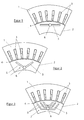
- FIG. 1 a section of a permanent magnet synchronous machine is shown, in which a portion of the stator 1 and a portion of the rotor 2 can be seen.
- the stator 1 is formed as a soft magnetic stator 1, which is formed with corresponding winding assemblies 3 for generating the Statorstrombelags.
- the windings arranged in suitable slots are typically designed as multiphase windings or three-phase windings.
- the permanent magnets 5 are here designed as so-called buried permanent magnets, this means that soft magnetic material of the rotor 2 is disposed between the permanent magnet 5 and the air gap 4, so that in addition to the inside conclusion to the air gap 4 towards a soft magnetic overlap of the permanent magnet 5 is present is.
- the overlap is carried out continuously, so that no grooves or slots are present in the region of the rotor between the individual permanent magnets 5 in the radial direction from the axis of rotation of the rotor.
- the movable magnet 6 is here preferably designed to be round and has a preferably transverse to the cylinder axis two-pole magnetization.
- the round shape makes twisting easier. In principle, however, other shapes are conceivable, as well as an arrangement on the edge of the permanent magnet 5 and not, as in the embodiment shown here, centrally.
- the movable magnet 6 now interacts magnetically with the permanent magnet 5.
- the field of excitement in the rotor 2 can be either weakened or strengthened as desired and required.
- the movable magnet 6 must, as already stated above, not be round. It could, for example, consist of a non-magnetic round element into which hard-magnetic material, for example a rectangular bar magnet, magnetic powder or the like is introduced. Although the design effort is given for this, but relatively small, since the movable elements 6 must be adjusted only against small magnetic forces.
- FIG. 2 an alternative embodiment is shown in which the same parts are each provided with the same reference numerals.
- the difference for example after FIG. 1 is that the buried permanent magnets 5 are not aligned. Instead, adjacent permanent magnets 5 are formed in a V-shaped arrangement and combined to form a group 7 of permanent magnets 5.
- This arrangement with a non-zero angle between the adjacent permanent magnets 5 allows a targeted influencing of the flux density in the Air gap 4 due to the different thicknesses of the material under which the individual regions of the permanent magnets 5 are buried.
- the preferred arrangement of the permanent magnets 5 in V-shape is chosen so that the tip of the Vs points in the direction of the axis of rotation of the rotor.
- the movable magnet 6 then sits in the top of the V-shaped arrangement.
- Corresponding arrangements in U-shape or the like are of course also conceivable.
- FIG. 3 shows a further alternative embodiment in which the same parts are also provided with the same reference numerals.
- the difference to the examples after FIG. 1 and FIG. 2 is in turn the arrangement of the permanent magnets 5. These are arranged as a group 7 in several different radial planes of the rotor 2. This, too, is a type of arrangement known per se, which offers the possibility of constructing flux densities and return areas constructively in such a way that an influence on the flux density in the air gap 4 results.
- the group 7 of the permanent magnets 5 has one of the movable elements 6. This in turn results in the same mode of action as in the embodiment according to the Figures 1 and 2 ,
Applications Claiming Priority (1)
| Application Number | Priority Date | Filing Date | Title |
|---|---|---|---|
| DE200810034975 DE102008034975A1 (de) | 2008-07-25 | 2008-07-25 | Permanenterregte Synchronmaschine |
Publications (1)
| Publication Number | Publication Date |
|---|---|
| EP2148407A1 true EP2148407A1 (fr) | 2010-01-27 |
Family
ID=41221611
Family Applications (1)
| Application Number | Title | Priority Date | Filing Date |
|---|---|---|---|
| EP09009264A Withdrawn EP2148407A1 (fr) | 2008-07-25 | 2009-07-16 | Machine synchrone à aimants permanents |
Country Status (2)
| Country | Link |
|---|---|
| EP (1) | EP2148407A1 (fr) |
| DE (1) | DE102008034975A1 (fr) |
Cited By (3)
| Publication number | Priority date | Publication date | Assignee | Title |
|---|---|---|---|---|
| US9397545B2 (en) | 2012-10-18 | 2016-07-19 | Audi Ag | Electric damper for a motor vehicle |
| CN109904959A (zh) * | 2019-04-05 | 2019-06-18 | 南京理工大学 | 一种便于弱磁的新能源汽车用永磁同步电机转子 |
| EP3646438B1 (fr) * | 2017-06-27 | 2021-11-03 | Schaeffler Technologies AG & Co. KG | Moteur à excitation par aimants permanents, doté de tiges magnétiques rotatives |
Families Citing this family (5)
| Publication number | Priority date | Publication date | Assignee | Title |
|---|---|---|---|---|
| DE102014206342A1 (de) * | 2014-04-02 | 2015-10-08 | Volkswagen Aktiengesellschaft | Rotor für eine elektrische Maschine mit Einrichtung zur Feldschwächung sowie elektrische Maschine |
| DE102019108047A1 (de) * | 2019-03-28 | 2020-10-01 | Volkswagen Aktiengesellschaft | Rotor für einen Permanentmagnet-Synchronmotor, Permanentmagnet-Synchronmotor und Fahrzeug |
| DE102020103890B4 (de) | 2020-02-14 | 2021-12-23 | Schaeffler Technologies AG & Co. KG | Elektrische Maschine, Verfahren zur Ansteuerung einer elektrischen Maschine und Rotor |
| DE102020117106B4 (de) | 2020-06-30 | 2022-03-17 | Audi Aktiengesellschaft | Läufer für eine rotierende elektrische Maschine |
| DE102020120821A1 (de) | 2020-08-06 | 2022-02-10 | Schaeffler Technologies AG & Co. KG | Elektromotor mit verdrehbarem Permanentmagnetelement in Aufnahmeloch |
Citations (2)
| Publication number | Priority date | Publication date | Assignee | Title |
|---|---|---|---|---|
| US20020070619A1 (en) | 1996-02-23 | 2002-06-13 | Noriyoshi Nishiyama | Electric vehicle using a motor |
| US20080169717A1 (en) | 2005-03-09 | 2008-07-17 | Nissan Motor Co.,Ltd. | Motor |
-
2008
- 2008-07-25 DE DE200810034975 patent/DE102008034975A1/de not_active Withdrawn
-
2009
- 2009-07-16 EP EP09009264A patent/EP2148407A1/fr not_active Withdrawn
Patent Citations (2)
| Publication number | Priority date | Publication date | Assignee | Title |
|---|---|---|---|---|
| US20020070619A1 (en) | 1996-02-23 | 2002-06-13 | Noriyoshi Nishiyama | Electric vehicle using a motor |
| US20080169717A1 (en) | 2005-03-09 | 2008-07-17 | Nissan Motor Co.,Ltd. | Motor |
Cited By (4)
| Publication number | Priority date | Publication date | Assignee | Title |
|---|---|---|---|---|
| US9397545B2 (en) | 2012-10-18 | 2016-07-19 | Audi Ag | Electric damper for a motor vehicle |
| EP3646438B1 (fr) * | 2017-06-27 | 2021-11-03 | Schaeffler Technologies AG & Co. KG | Moteur à excitation par aimants permanents, doté de tiges magnétiques rotatives |
| US11223251B2 (en) | 2017-06-27 | 2022-01-11 | Schaeffler Technologies AG & Co. KG | Permanent magnet energized motor with rotatable bar magnets |
| CN109904959A (zh) * | 2019-04-05 | 2019-06-18 | 南京理工大学 | 一种便于弱磁的新能源汽车用永磁同步电机转子 |
Also Published As
| Publication number | Publication date |
|---|---|
| DE102008034975A1 (de) | 2010-02-04 |
Similar Documents
| Publication | Publication Date | Title |
|---|---|---|
| EP2148407A1 (fr) | Machine synchrone à aimants permanents | |
| DE69833081T2 (de) | Motor mit innerem Permanentmagnetrotor | |
| WO2013135377A2 (fr) | Machine électrique efficace | |
| DE102013219020A1 (de) | Elektrische Drehmaschine mit innenliegenden Dauermagneten | |
| DE102010029614A1 (de) | Fraktionierte Schlitz Multiphasen-Maschinen mit offenen Schlitzen für eine vereinfachte Leitereinführung in einen Stator | |
| DE102013110413A1 (de) | Rotor und drehende elektrische Maschine | |
| EP2807727A1 (fr) | Rotor pour machine électrique tournante et machine électrique tournante | |
| DE102020130359A1 (de) | Elektrische maschine mit geräuschmindernden rotorkerben | |
| DE102016209711A1 (de) | Rotorkern | |
| WO2011003718A2 (fr) | Stator et procédé de production d'un stator | |
| DE102007001828A1 (de) | Getriebeeinrichtung mit einem inneren und einem äußeren Rotorteil, welche von einem inneren und einem äußeren Statorteil umgeben sind | |
| DE102021101898A1 (de) | Elektrische Maschine und Antriebsstrang für ein hybrid- oder vollelektrisch antreibbares Kraftfahrzeug | |
| DE102020116423A1 (de) | Rotor und elektromechanischer Energiewandler mit toroidaler Erregerspule und Kraftfahrzeug | |
| WO2010023038A2 (fr) | Rotor pour une machine électrique à couple de détente réduit | |
| DE102020129142B4 (de) | Läufer für eine rotierende elektrische Maschine | |
| WO2022152931A1 (fr) | Fabrication d'une unité magnétique pour une machine électrique tournante | |
| DE102021104785A1 (de) | Läufer für eine Synchronmaschine | |
| DE102021211050A1 (de) | Elektromotor mit verschiedenen aufeinandergestapelten rotorsegmenten und verfahren zum ausgestalten desselben | |
| DE102017127611A1 (de) | Synchron-Reluktanzmotor mit durch Permanentmagnete gesättigtem magnetischen Nebenschlusspfad | |
| WO2020177964A1 (fr) | Rotor pour un machine électrique à excitation permanente avec structure support | |
| DE102017101913A1 (de) | Elektromotor mit eingebettetem Dauermagnet | |
| DE102011055766A1 (de) | Drehstrom-Synchronmaschine | |
| DE102020113938A1 (de) | Blechpaket für eine permanenterregte Synchronmaschine mit vergrößerten Magnettaschen zum Erhöhen eines Drehmoments durch Reluktanz sowie Synchronmaschine und Kraftfahrzeug | |
| EP1758229B1 (fr) | Moteur électrique | |
| DE102016100744B3 (de) | Elektrische Maschine |
Legal Events
| Date | Code | Title | Description |
|---|---|---|---|
| PUAI | Public reference made under article 153(3) epc to a published international application that has entered the european phase |
Free format text: ORIGINAL CODE: 0009012 |
|
| AK | Designated contracting states |
Kind code of ref document: A1 Designated state(s): AT BE BG CH CY CZ DE DK EE ES FI FR GB GR HR HU IE IS IT LI LT LU LV MC MK MT NL NO PL PT RO SE SI SK SM TR |
|
| AX | Request for extension of the european patent |
Extension state: AL BA RS |
|
| 17P | Request for examination filed |
Effective date: 20100605 |
|
| 17Q | First examination report despatched |
Effective date: 20131002 |
|
| STAA | Information on the status of an ep patent application or granted ep patent |
Free format text: STATUS: THE APPLICATION HAS BEEN WITHDRAWN |
|
| 18W | Application withdrawn |
Effective date: 20131121 |