EP2148342A1 - Schalteinrichtung, insbesondere für ein Kraftfahrzeug - Google Patents
Schalteinrichtung, insbesondere für ein Kraftfahrzeug Download PDFInfo
- Publication number
- EP2148342A1 EP2148342A1 EP08013509A EP08013509A EP2148342A1 EP 2148342 A1 EP2148342 A1 EP 2148342A1 EP 08013509 A EP08013509 A EP 08013509A EP 08013509 A EP08013509 A EP 08013509A EP 2148342 A1 EP2148342 A1 EP 2148342A1
- Authority
- EP
- European Patent Office
- Prior art keywords
- switching device
- housing
- actuating element
- closure
- closure lid
- Prior art date
- Legal status (The legal status is an assumption and is not a legal conclusion. Google has not performed a legal analysis and makes no representation as to the accuracy of the status listed.)
- Granted
Links
- 230000006835 compression Effects 0.000 claims description 10
- 238000007906 compression Methods 0.000 claims description 10
- 230000000881 depressing effect Effects 0.000 claims description 4
- 238000007789 sealing Methods 0.000 abstract 2
- 101100495270 Caenorhabditis elegans cdc-26 gene Proteins 0.000 description 3
- 230000000994 depressogenic effect Effects 0.000 description 3
- 230000015556 catabolic process Effects 0.000 description 2
- 238000004891 communication Methods 0.000 description 1
- 238000006073 displacement reaction Methods 0.000 description 1
- 238000000034 method Methods 0.000 description 1
- 230000007935 neutral effect Effects 0.000 description 1
- 230000002040 relaxant effect Effects 0.000 description 1
Images


Classifications
-
- H—ELECTRICITY
- H01—ELECTRIC ELEMENTS
- H01H—ELECTRIC SWITCHES; RELAYS; SELECTORS; EMERGENCY PROTECTIVE DEVICES
- H01H3/00—Mechanisms for operating contacts
- H01H3/02—Operating parts, i.e. for operating driving mechanism by a mechanical force external to the switch
- H01H3/022—Emergency operating parts, e.g. for stop-switch in dangerous conditions
-
- H—ELECTRICITY
- H01—ELECTRIC ELEMENTS
- H01H—ELECTRIC SWITCHES; RELAYS; SELECTORS; EMERGENCY PROTECTIVE DEVICES
- H01H13/00—Switches having rectilinearly-movable operating part or parts adapted for pushing or pulling in one direction only, e.g. push-button switch
- H01H13/02—Details
- H01H13/04—Cases; Covers
-
- H—ELECTRICITY
- H01—ELECTRIC ELEMENTS
- H01H—ELECTRIC SWITCHES; RELAYS; SELECTORS; EMERGENCY PROTECTIVE DEVICES
- H01H13/00—Switches having rectilinearly-movable operating part or parts adapted for pushing or pulling in one direction only, e.g. push-button switch
- H01H13/50—Switches having rectilinearly-movable operating part or parts adapted for pushing or pulling in one direction only, e.g. push-button switch having a single operating member
- H01H13/56—Switches having rectilinearly-movable operating part or parts adapted for pushing or pulling in one direction only, e.g. push-button switch having a single operating member the contact returning to its original state upon the next application of operating force
- H01H13/562—Switches having rectilinearly-movable operating part or parts adapted for pushing or pulling in one direction only, e.g. push-button switch having a single operating member the contact returning to its original state upon the next application of operating force making use of a heart shaped cam
-
- H—ELECTRICITY
- H01—ELECTRIC ELEMENTS
- H01H—ELECTRIC SWITCHES; RELAYS; SELECTORS; EMERGENCY PROTECTIVE DEVICES
- H01H3/00—Mechanisms for operating contacts
- H01H3/02—Operating parts, i.e. for operating driving mechanism by a mechanical force external to the switch
- H01H3/20—Operating parts, i.e. for operating driving mechanism by a mechanical force external to the switch wherein an auxiliary movement thereof, or of an attachment thereto, is necessary before the main movement is possible or effective, e.g. for unlatching, for coupling
Definitions
- the invention relates to a switching device, in particular for a motor vehicle, having a housing, an actuating element and a safety device for preventing unintentional loading of the actuating element.
- the EP 1 160 812 A2 discloses a switching device of the type mentioned, in which the actuating element is designed as a pressure knob, by the rotational movement of two microswitches are actuated, which generate two different electrical emergency signals.
- the actuating element is locked in the rest position by means formed on it locking cams, which engage in corresponding recesses, in an upper housing part are formed.
- the locking cams together with the locking recesses a safety device which can be unlocked by depressing the knob, the locking cams come free from the recesses.
- a rotational movement of the actuating element for actuating the microswitch can thus be carried out only in the depressed low position.
- a disadvantage is the relatively complicated operation of the switching device to be considered, during which the actuator must be kept in its depressed position. Another disadvantage is the relatively complicated structure of the switching device.
- the invention has for its object to provide a switching device of the type mentioned, in which both the operation, in particular the unlocking of the safety device, as well as the structure is substantially simplified.
- the actuating element is associated with a pivotally mounted closure lid whose pivot axis is limited height adjustable relative to the housing, wherein the lid covers the actuating element in a first closed position and free in a second open position for loading.
- the closure cap is preferably in the first position locked against the housing.
- the closure lid is mounted on a height-adjustable frame in the frame, which is biased against the direction of loading of the actuating element of the switch by compression springs, which are supported on the one hand to the housing and the other on the frame.
- an adjustable by depressing the closure cover end position of the closure lid is provided in a further embodiment in which the closure lid is unlocked and the frame is under compression of the compression springs in its immersed position in the housing.
- the locking of the closure lid is expediently carried out in its first position by means of a latching cam mechanism, which consists of a cam track formed on the closure lid and a latch formed in the housing.
- a latching cam mechanism which consists of a cam track formed on the closure lid and a latch formed in the housing.
- the curved path is formed on a locking tab of the closure lid, which is received by a limited in the housing receiving shaft.
- closure lid is securely held in its unlocked or opened position
- the closure lid is in the direction of its open position by means of at least one helical spring biased.
- the actuating element is provided on a displaceably mounted switching element, which is arranged in the housing.
- the switching element is preferably arranged in a rectangular in plan view shaft within the housing.
- the frame is expediently arranged outside the shaft. The nested arrangement of said components serves in particular to increase the dimensional stability of the switching device.
- the electrical switch is designed as a push-button.
- the movable electrical contact elements of the key switch are arranged in each case a dome-like region of a flexible switching mat, the underside of which comes to rest on a circuit board to which the stationary electrical contact elements of the key switch are provided.
- the switching device When using the switching device in a motor vehicle, this is preferably installed in a roof trim or a center console of the motor vehicle. If the switching device is installed together with other electrical components, such as interior lighting with associated switches, the closure lid can be arranged in a plane with these components and immediately adjacent thereto, as by the displacement of the closure lid in height, which is associated with the pivoting , sufficient space for opening the cap to reach the actuator available stands.
- the switching device is finally used as an emergency call, which requires a considerable increase in traffic safety.
- the switching device consists essentially of an electrical switch 20 with an actuating element 2 and a safety device 7, 14-17 for preventing unintentional loading of the actuating element 2.
- the switch 20 has a housing 1, in which a the actuating element 2 supporting switching element 3, a flexible switching mat 4 and arranged below the switching mat 4 circuit board 5 are arranged.
- the housing 1 is closed in its lower part by a base 6.
- the switch 20 comprises not shown movable electrical contact elements, which are arranged in dome-like areas 21 of the flexible switching mat 4 and which also interact with fixed electrical contact elements also not shown, which are arranged on the circuit board 5.
- the switching element 3 is received in a limited in the housing 1 shaft 19, the shaft wall 18 has a rectangular plan view.
- For one Bias of the frame 8 in the direction opposite to the direction of actuation provide compression springs 9, 10, 11, 12, which are supported on the one hand at the corners of the frame 8 and on the other hand inside the housing 1, wherein the frame 8 between the shaft wall 18 and inner surfaces the housing walls is arranged.
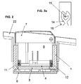
- the closure lid 7 is moved by means of at least one coil spring 13 (leg spring) in its open position ( Fig. 5 ) is biased and is provided with a locking tab 16 which, together with a arranged on the shaft wall 18 latch 15 (FIG. Fig. 2a ) forms the safety device.
- the detent pawl 15 cooperates with a locking lug 16 formed in the cam track 14 of a so-called heart curve, together with the detent pawl 15 forms a latching cam mechanism.
- the locking tab 16 is received in the first closed position of the closure lid 7 by a receiving shaft 17 formed in the housing 1.
- 2a is the housing 1 in a correspondingly sized opening of a vehicle trim 22, such as a roof panel installed.
- a vehicle trim 22 such as a roof panel installed.
- the closure lid 7 is closed and locked or locked by means of the latching cam mechanism, the larger scale in Fig. 2a is shown.
- the captively mounted frame 8 upwardly biasing compression springs 9, 10, 11, 12 are substantially relaxed.
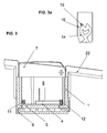
- 3a is shown an end position of the switching device, which is occupied by its components after the closure lid 7 has been pressed down.
- the compression springs 9, 10, 11, 12 are compressed, wherein the detent pawl 15 in the latching curve 14 in Fig. 3a shown position in which the closure lid 7 is unlocked.
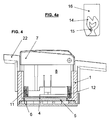
- FIG. 4, 4a An unlocked position of the switching device is in the Fig. 4, 4a shown, in which the locking of the closure lid 7 is no longer effective and the frame 8 has been moved to the closure lid 7 by relaxing the compression springs 9, 10, 11, 12 upwards.
- Fig. 4a can be seen, is the latch 15 in the exit region of the cam track 14, so that an adjustment of the closure cap 7 in the in Fig. 5 shown, open position is possible.
- the actuating element 2 of the electrical switch 20 is freely accessible and can be actuated if necessary.
Abstract
Description
- Die Erfindung bezieht sich auf eine Schalteinrichtung, insbesondere für ein Kraftfahrzeug, mit einem Gehäuse, einem Betätigungselement und einer Sicherheitsvorrichtung zum Verhindern einer unbeabsichtigten Beaufschlagung des Betätigungselementes.
- Bei Kraftfahrzeugen ist es bekannt, im Gefahrenfall, zum Beispiel bei einem Unfall oder einer Panne, mittels eines vorprogrammierten Kommunikationsendgerätes bei der Polizei, einem Pannendienst oder einer Notrufzentrale eines Kraftfahrzeugherstellers einen Alarm auszulösen.
- Die
EP 1 160 812 A2 offenbart eine Schalteinrichtung der eingangs erwähnten Art, bei der das Betätigungselement als Druck-Drehknopf ausgebildet ist, durch dessen Drehbewegung zwei Mikroschalter betätigt werden, die zwei verschiedene elektrische Notrufsignale erzeugen. Um ein unbeabsichtigtes Betätigen der als Notrufsschalter dienenden Schalteinrichtung zu verhindern, ist das Betätigungselement in der Ruhestellung mittels an ihm angeformter Rastnocken verriegelt, die in entsprechende Rastausnehmungen eingreifen, die in einem Gehäuseoberteil ausgebildet sind. Die Rastnocken bilden zusammen mit den Rastausnehmungen eine Sicherheitsvorrichtung, die durch Niederdrücken des Drehknopfes entriegelbar ist, wobei die Rastnocken aus den Rastausnehmungen frei kommen. Eine Drehbewegung des Betätigungselementes zum Betätigen der Mikroschalter kann somit nur in dessen nieder gedrückter Stellung erfolgen. Als nachteilig ist der relativ komplizierte Betätigungsvorgang der Schalteinrichtung anzusehen, während dessen das Betätigungselement in seiner niedergedrückten Stellung gehalten werden muss. Ein weiterer Nachteil liegt in dem verhältnismäßig komplizierten Aufbau der Schalteinrichtung. - Der Erfindung liegt die Aufgabe zugrunde, eine Schalteinrichtung der eingangs genannten Art zu schaffen, bei der sowohl die Betätigung, insbesondere das Entriegeln der Sicherheitsvorrichtung, als auch der Aufbau wesentlich vereinfacht ist.
- Die Aufgabe wird erfindungsgemäß dadurch gelöst, dass dem Betätigungselement ein schwenkbar gelagerter Verschlussdeckel zugeordnet ist, dessen Schwenkachse gegenüber dem Gehäuse begrenzt höhenverstellbar gelagert ist, wobei der Deckel das Betätigungselement in einer ersten geschlossenen Position überdeckt und in einer zweiten geöffneten Position zur Beaufschlagung frei gibt.
- Aufgrund dieser Maßnahmen ist eine versehentliche Beaufschlagung des Betätigungselementes wirksam verhindert.
- Der Verschlussdeckel ist vorzugsweise in der ersten Position gegenüber dem Gehäuse arretiert. Nach einer vorteilhaften Weiterbildung ist der Verschlussdeckel an einem im Gehäuse höhenverstellbaren Rahmen gelagert, der entgegen der Beaufschlagungsrichtung des Betätigungselementes des Schalters durch Druckfedern vorgespannt ist, die zum einen am Gehäuse und zum anderen am Rahmen abgestützt sind. Durch diese Maßnahme wird eine besonders kompakte Bauweise der Schalteinrichtung erreicht.
- Zur wesentlichen Vereinfachung des Entriegelungsvorgangs der Sicherheitsvorrichtung ist bei einer weiteren Ausgestaltung eine durch Niederdrücken des Verschlussdeckels einstellbare Endlage des Verschlussdeckels vorgesehen, in der der Verschlussdeckel entriegelt ist und sich der Rahmen unter Zusammendrücken der Druckfedern in seiner eingetauchten Position im Gehäuse befindet.
- Um eine besonders wirksame Verriegelung des Verschlussdeckels mit relativ einfachen Mitteln zu erreichen, erfolgt zweckmäßigerweise die Arretierung des Verschlussdeckels in seiner ersten Position mittels eines Rastkurvenmechanismus, der aus einer am Verschlussdeckel ausgebildeten Kurvenbahn sowie einer im Gehäuse angeformten Rastklinke besteht. Bevorzugt ist die Kurvenbahn an einer Arretierungslasche des Verschlussdeckels ausgebildet, die von einem im Gehäuse begrenzten Aufnahmeschacht aufgenommen wird.
- Damit der Verschlussdeckel in seiner entriegelten bzw. geöffneten Position sicher gehalten ist, ist bei einer weiteren Ausführungsform der Verschlussdeckel mittels mindestens einer Schraubenfeder in Richtung seiner geöffneten Position vorgespannt.
- In weiterer Ausgestaltung ist das Betätigungselement an einem verschiebbar gelagerten Schaltglied vorgesehen, das im Gehäuse angeordnet ist. Das Schaltglied ist dabei vorzugsweise in einem in Draufsicht rechteckigen Schacht innerhalb des Gehäuses angeordnet. Zweckmäßigerweise ist der Rahmen außerhalb des Schachts angeordnet. Die ineinander geschachtelte Anordnung der genannten Bauteile dient insbesondere der Erhöhung der Formfestigkeit der Schalteinrichtung.
- Für ein schnelles und zuverlässiges Erzeugen elektrischer Signale ist der elektrische Schalter als Tastschalter ausgeführt ist. Die beweglichen elektrischen Kontaktelemente des Tastschalters sind dabei in jeweils einem domartigen Bereich einer flexiblen Schaltmatte angeordnet, deren Unterseite flächig auf einer Leiterplatte zur Anlage kommt, an der die ortsfesten elektrischen Kontaktelemente des Tastschalters vorgesehen sind.
- Bei der Verwendung der Schalteinrichtung in einem Kraftfahrzeug ist diese bevorzugt in eine Dachverkleidung oder eine Mittelkonsole des Kraftfahrzeuges einbaubar. Wird die Schalteinrichtung gemeinsam mit weiteren elektrischen Komponenten, wie beispielsweise einer Innenbeleuchtung mit zugeordneten Schaltern, verbaut, kann der Verschlussdeckel in einer Ebene mit diesen Komponenten und unmittelbar benachbart dazu angeordnet werden, da durch die Verlagerung des Verschlussdeckels in der Höhe, die mit dem Verschwenken einhergeht, ausreichender Platz zur Öffnung des Verschlussdeckels zum Erreichen des Betätigungselementes zur Verfügung steht.
- Die Schalteinrichtung ist schließlich als Notrufschalter einsetzbar, was eine beträchtliche Erhöhung der Verkehrssicherheit bedingt.
- Es versteht sich, dass die vorstehend genannten und nachstehend noch zu erläuternden Merkmale nicht nur in der jeweils angegebenen Kombination, sondern auch in anderen Kombinationen verwendbar sind. Der Rahmen der Erfindung ist nur durch die Ansprüche definiert.
- Die Erfindung wird im Folgenden anhand eines Ausführungsbeispiels unter Bezugnahme auf die zugehörigen Zeichnungen näher erläutert. Es zeigt:
- Fig. 1
- eine Explosionsdarstellung einer erfindungsgemäßen Schalteinrichtung;
- Fig. 2
- die Schalteinrichtung gemäß
Fig. 1 in einer - und 2a
- Teilschnittdarstellung in zusammengebautem Zustand in einer Ruhestellung sowie eine Einzelheit einer Sicherheitsvorrichtung;
- Fig. 3 und 3a
- die Schalteinrichtung gemäß
Fig. 1 oder2 in einer Teilschnittdarstellung in zusammengebautem Zustand in einer Zwischenposition der Sicherheitsvorrichtung sowie die Einzelheit gemäßFig. 2a ; - Fig. 4und 4a
- die Schalteinrichtung gemäß
Fig. 1 in einerTeilschnittdarstellung in zusammengebautem Zustand in einer entriegelten Position der Sicherheitsvorrichtung sowie die Einzelheit gemäßFig. 2a oder3a ; - Fig. 5
- die Schalteinrichtung gemäß
Fig. 1 - 4 in einer Bereitschaftsposition mit geöffnetem Verschlussdeckel. - Die Schalteinrichtung besteht im Wesentlichen aus einem elektrischen Schalter 20 mit einem Betätigungselement 2 sowie einer Sicherheitsvorrichtung 7, 14 - 17 zum Verhindern einer unbeabsichtigten Beaufschlagung des Betätigungselementes 2. Der Schalter 20 weist ein Gehäuse 1 auf, in dem ein das Betätigungselement 2 tragendes Schaltglied 3, eine flexible Schaltmatte 4 sowie eine unterhalb der Schaltmatte 4 angeordnete Leiterplatte 5 angeordnet sind. Das Gehäuse 1 ist in seinem unteren Bereich durch einen Sockel 6 verschlossen. Außerdem umfasst der Schalter 20 nicht gezeigte bewegliche elektrische Kontaktelemente, die in domartigen Bereichen 21 der flexiblen Schaltmatte 4 angeordnet sind und die mit ebenfalls nicht gezeigten ortsfesten elektrischen Kontaktelementen zusammen wirken, die an der Leiterplatte 5 angeordnet sind. Das Schaltglied 3 ist in einem im Gehäuse 1 begrenzten Schacht 19 aufgenommen, dessen Schachtwand 18 eine rechteckförmige Draufsicht aufweist. Ein Verschlussdeckel 7, der an einem Rahmen 8 schwenkbar gelagert ist, überdeckt in einer ersten geschlossenen Stellung das Betätigungselement 2 des Schalters 20. Die Lagerung des Verschlussdeckels 7 erfolgt mittels am Rahmen 8 angeformter Lagerzapfen 23, wobei der Rahmen 8 im Gehäuse 1 höhenverstellbar und unverlierbar angeordnet ist. Für eine Vorspannung des Rahmens 8 in der der Betätigungsrichtung entgegengesetzten Richtung sorgen Druckfedern 9, 10, 11, 12, die sich einerseits an den Ecken des Rahmens 8 und andererseits im Inneren des Gehäuses 1 abstützen, wobei der Rahmen 8 zwischen der Schachtwand 18 und innen liegenden Flächen der Gehäusewände angeordnet ist. Beim Öffnen des Verschlussdeckels 7 verschiebt sich dessen Schwenkachse nach oben.
- Der Verschlussdeckel 7 wird mittels mindestens einer Schraubenfeder 13 (Schenkelfeder) in seine geöffnete Position (
Fig. 5 ) vorgespannt und ist mit einer Arretierungslasche 16 versehen, die zusammen mit einer an der Schachtwand 18 angeordneten Rastklinke 15 (Fig. 2a ) die Sicherheitsvorrichtung bildet. Die Rastklinke 15 wirkt dabei mit einer in der Arretierungslasche 16 ausgebildeten Kurvenbahn 14 einer so genannten Herzkurve, zusammen, die mit der Rastklinke 15 einen Rastkurvenmechanismus bildet. Die Arretierungslasche 16 wird in der ersten geschlossenen Position des Verschlussdeckels 7 von einem im Gehäuse 1 ausgebildeten Aufnahmeschacht 17 aufgenommen. - Gemäß den
Fig. 2, 2a ist das Gehäuse 1 in eine entsprechend dimensionierte Öffnung einer Fahrzeugverkleidung 22, beispielsweise einer Dachverkleidung, eingebaut. In der dargestellten Ruhe- bzw. Neutralposition der Schalteinrichtung ist der Verschlussdeckel 7 geschlossen und mittels des Rastkurvenmechanismus verriegelt bzw. arretiert, der in größerem Maßstab inFig. 2a dargestellt ist. Die den unverlierbar gelagerten Rahmen 8 nach oben vorspannenden Druckfedern 9, 10, 11, 12 sind im Wesentlichen entspannt. - In den
Fig. 3, 3a ist eine Endlage der Schalteinrichtung dargestellt, die von deren Bauteilen eingenommen wird, nachdem der Verschlussdeckel 7 nach unten gedrückt worden ist. Durch das Niederdrücken des Verschlussdeckels 7 in die erwähnte Endlage, die auch als "gedrückte Position" bezeichnet werden kann, werden die Druckfedern 9, 10, 11, 12 komprimiert, wobei die Rastklinke 15 in der Rastkurve 14 die inFig. 3a gezeigte Position einnimmt, in der der Verschlussdeckel 7 entriegelt ist. - Eine entriegelte Position der Schalteinrichtung ist in den
Fig. 4, 4a dargestellt, in der die Arretierung des Verschlussdeckels 7 nicht mehr wirksam ist und der Rahmen 8 mit dem Verschlussdeckel 7 durch Entspannen der Druckfedern 9, 10, 11, 12 nach oben verschoben wurde. Wie insbesondereFig. 4a zu entnehmen ist, befindet sich die Rastklinke 15 im Ausgangsbereich der Kurvenbahn 14, so dass ein Verstellen des Verschlussdeckels 7 in die inFig. 5 gezeigte, geöffnete Position möglich ist. In der geöffneten Position des Verschlussdeckels 7 ist das Betätigungselement 2 des elektrischen Schalters 20 frei zugänglich und kann bei Bedarf betätigt werden.
Claims (14)
- Schalteinrichtung, insbesondere für ein Kraftfahrzeug, mit einem Gehäuse (1), einem Betätigungselement (2) und einer Sicherheitsvorrichtung (7, 14 - 16) zum Verhindern einer unbeabsichtigten Beaufschlagung des Betätigungselementes (2), dadurch gekennzeichnet, dass dem Betätigungselement (2) ein schwenkbar gelagerter Verschlussdeckel (7) zugeordnet ist, dessen Schwenkachse gegenüber dem Gehäuse (1) begrenzt höhenverstellbar gelagert ist, wobei der Verschlussdeckel (7) das Betätigungselement (2) in einer ersten geschlossenen Position überdeckt und in einer zweiten geöffneten Position zur Beaufschlagung frei gibt.
- Schalteinrichtung nach Anspruch 1, dadurch gekennzeichnet, dass der Verschlussdeckel (7) in der ersten Position gegenüber dem Gehäuse (1) arretiert ist.
- Schalteinrichtung nach Anspruch 1 oder 2, dadurch gekennzeichnet, dass der Verschlussdeckel (7) an einem im Gehäuse (1) höhenverstellbaren Rahmen (8) gelagert ist, der entgegen der Beaufschlagungsrichtung des Betätigungselementes (2) des Schalters (20) durch Druckfedern (9) vorgespannt ist, die zum einen am Gehäuse (1) und zum anderen am Rahmen (8) abgestützt sind.
- Schalteinrichtung nach Anspruch 3, dadurch gekennzeichnet, dass eine durch Niederdrücken des Verschlussdeckels (7) einstellbare Endlage des Verschlussdeckels (7) vorgesehen ist, in der der Verschlussdeckel (7) entriegelt ist und sich der Rahmen (8) unter Zusammendrücken der Druckfedern (9) in seiner eingetauchten Position im Gehäuse (1) befindet.
- Schalteinrichtung nach einem der Ansprüche 1 bis 4, dadurch gekennzeichnet, dass die Arretierung des Verschlussdeckels (7) in seiner ersten Position mittels eines Rastkurvenmechanismus erfolgt, der aus einer am Verschlussdeckel (7) ausgebildeten Kurvenbahn (14) sowie einer im Gehäuse (1) schwenkbar angeordneten Rastklinke (15) besteht.
- Schalteinrichtung nach Anspruch 5, dadurch gekennzeichnet, dass die Kurvenbahn (14) an einer Arretierungslasche (16) des Verschlussdeckels (7) ausgebildet ist, die von einem im Gehäuse (1) begrenzten Aufnahmeschacht (17) aufgenommen wird.
- Schalteinrichtung nach einem der Ansprüche 1 bis 6, dadurch gekennzeichnet, dass der Verschlussdeckel (7) mittels mindestens einer Schraubenfeder (13) in Richtung seiner geöffneten Position vorgespannt ist.
- Schalteinrichtung nach einem der Ansprüche 1 bis 7, dadurch gekennzeichnet, dass das Betätigungselement (2) an einem verschiebbar gelagerten Schaltglied (3) vorgesehen ist, das im Gehäuse (1) angeordnet ist.
- Schalteinrichtung nach Anspruch 8, dadurch gekennzeichnet, dass das Schaltglied (3) in einem in Draufsicht rechteckigen Schacht (19) innerhalb des Gehäuses (1) angeordnet ist.
- Schalteinrichtung nach Anspruch 9, dadurch gekennzeichnet, dass der Rahmen (8) außerhalb des Schachts (19) unverlierbar angeordnet ist.
- Schalteinrichtung nach einem der Ansprüche 1 bis 10, dadurch gekennzeichnet, dass der elektrische Schalter (2.0) als Tastschalter ausgeführt ist.
- Schalteinrichtung nach Anspruch 11, dadurch gekennzeichnet, dass bewegliche elektrische Kontaktelemente des Tastschalters (20) in jeweils einem domartigen Bereich (21) einer flexiblen Schaltmatte (4) angeordnet sind, deren Unterseite flächig auf einer Leiterplatte (5) zur Anlage kommt, an der ortsfeste elektrische Kontaktelemente vorgesehen sind.
- Schalteinrichtung nach einem der Ansprüche 1 bis 12, dadurch gekennzeichnet, dass die Schalteinrichtung in eine Dachverkleidung oder eine Mittelkonsole eines Kraftfahrzeuges einbaubar ist.
- Schalteinrichtung nach einem der Ansprüche 1 bis 13, dadurch gekennzeichnet, dass der Schalter der Schalteinrichtung als Notrufschalter einsetzbar ist.
Priority Applications (1)
| Application Number | Priority Date | Filing Date | Title |
|---|---|---|---|
| EP20080013509 EP2148342B1 (de) | 2008-07-26 | 2008-07-26 | Schalteinrichtung, insbesondere für ein Kraftfahrzeug |
Applications Claiming Priority (1)
| Application Number | Priority Date | Filing Date | Title |
|---|---|---|---|
| EP20080013509 EP2148342B1 (de) | 2008-07-26 | 2008-07-26 | Schalteinrichtung, insbesondere für ein Kraftfahrzeug |
Publications (2)
| Publication Number | Publication Date |
|---|---|
| EP2148342A1 true EP2148342A1 (de) | 2010-01-27 |
| EP2148342B1 EP2148342B1 (de) | 2013-01-09 |
Family
ID=39971111
Family Applications (1)
| Application Number | Title | Priority Date | Filing Date |
|---|---|---|---|
| EP20080013509 Active EP2148342B1 (de) | 2008-07-26 | 2008-07-26 | Schalteinrichtung, insbesondere für ein Kraftfahrzeug |
Country Status (1)
| Country | Link |
|---|---|
| EP (1) | EP2148342B1 (de) |
Cited By (1)
| Publication number | Priority date | Publication date | Assignee | Title |
|---|---|---|---|---|
| DE102012005960A1 (de) * | 2012-03-23 | 2013-09-26 | Johnson Electric Germany GmbH & Co. KG | Elektrische Schalteranordnung, umfassend ein Schaltergehäuse und zumindest einen im Schaltergehäuse geführten Taster |
Citations (4)
| Publication number | Priority date | Publication date | Assignee | Title |
|---|---|---|---|---|
| US5144323A (en) * | 1991-05-22 | 1992-09-01 | Tendler Technologies, Inc. | Protected switch for emergency location system |
| EP1160812A2 (de) | 2000-06-02 | 2001-12-05 | Reitter & Schefenacker GmbH & Co. KG | Notrufschalter für Fahrzeuge, insbesondere für Kraftfahrzeuge |
| US20020020614A1 (en) * | 2000-06-16 | 2002-02-21 | Deere & Company, A Delaware Corporation | Cover for vehicle control switch |
| DE102004042573B3 (de) * | 2004-09-02 | 2005-10-13 | Novar Gmbh | Manueller Gefahrenmelder |
-
2008
- 2008-07-26 EP EP20080013509 patent/EP2148342B1/de active Active
Patent Citations (4)
| Publication number | Priority date | Publication date | Assignee | Title |
|---|---|---|---|---|
| US5144323A (en) * | 1991-05-22 | 1992-09-01 | Tendler Technologies, Inc. | Protected switch for emergency location system |
| EP1160812A2 (de) | 2000-06-02 | 2001-12-05 | Reitter & Schefenacker GmbH & Co. KG | Notrufschalter für Fahrzeuge, insbesondere für Kraftfahrzeuge |
| US20020020614A1 (en) * | 2000-06-16 | 2002-02-21 | Deere & Company, A Delaware Corporation | Cover for vehicle control switch |
| DE102004042573B3 (de) * | 2004-09-02 | 2005-10-13 | Novar Gmbh | Manueller Gefahrenmelder |
Cited By (3)
| Publication number | Priority date | Publication date | Assignee | Title |
|---|---|---|---|---|
| DE102012005960A1 (de) * | 2012-03-23 | 2013-09-26 | Johnson Electric Germany GmbH & Co. KG | Elektrische Schalteranordnung, umfassend ein Schaltergehäuse und zumindest einen im Schaltergehäuse geführten Taster |
| US9087661B2 (en) | 2012-03-23 | 2015-07-21 | Johnson Electric S.A. | Electrical switch arrangement |
| DE102012005960B4 (de) * | 2012-03-23 | 2017-06-08 | Johnson Electric Germany GmbH & Co. KG | Elektrische Schalteranordnung, umfassend ein Schaltergehäuse und zumindest einen im Schaltergehäuse geführten Taster |
Also Published As
| Publication number | Publication date |
|---|---|
| EP2148342B1 (de) | 2013-01-09 |
Similar Documents
| Publication | Publication Date | Title |
|---|---|---|
| EP2766912B1 (de) | Mechanisch sperrbarer handschalter | |
| DE112007000579B4 (de) | Verstärkter Schlüsselanhänger | |
| EP1214726A1 (de) | Wippenschalter für jeweils einen zweistufigen betätigungshub | |
| EP1037229B1 (de) | Hub-Schiebe-Schalter | |
| EP0563530B1 (de) | Lastschaltleiste | |
| EP1393972B1 (de) | Schalteinrichtung für eine Fahrzeughupe | |
| DE102011011299A1 (de) | Elektrischer Schalter | |
| EP2148342B1 (de) | Schalteinrichtung, insbesondere für ein Kraftfahrzeug | |
| EP2187415B1 (de) | Bahn-Kippschalter | |
| EP1247286B1 (de) | Elektrischer schalter | |
| EP1702796B1 (de) | Kombinierter Druck- und Drehschalter für ein Kraftfahrzeug | |
| EP0956578B1 (de) | Schaltgerät mit schnelleinschaltung | |
| EP0897584B1 (de) | Kippschalter, insbesondere für fensterheber in einem kraftfahrzeug | |
| DE102008024120B3 (de) | Hub-Schiebe-Schalter | |
| EP1748453B1 (de) | Elektrischer Schalter | |
| DE102007001476B4 (de) | Gassackmodul | |
| DE3608703C2 (de) | ||
| EP1654747B1 (de) | Elektrischer schalter | |
| WO2003041100A2 (de) | Elektrischer schalter | |
| EP1777717B1 (de) | Elektrischer Drucktastenschalter | |
| DE102011007915B4 (de) | Elektromechanischer Schalter | |
| EP2504850B1 (de) | Elektrischer schalter | |
| DE3835931C2 (de) | Drucktastenschalter mit einer Rastverriegelung | |
| DE10119558A1 (de) | Wippschalter | |
| EP0663676B1 (de) | Tastschalter für ein Flurförderzeug, insbesondere Kommissionierer |
Legal Events
| Date | Code | Title | Description |
|---|---|---|---|
| PUAI | Public reference made under article 153(3) epc to a published international application that has entered the european phase |
Free format text: ORIGINAL CODE: 0009012 |
|
| AK | Designated contracting states |
Kind code of ref document: A1 Designated state(s): AT BE BG CH CY CZ DE DK EE ES FI FR GB GR HR HU IE IS IT LI LT LU LV MC MT NL NO PL PT RO SE SI SK TR |
|
| AX | Request for extension of the european patent |
Extension state: AL BA MK RS |
|
| 17P | Request for examination filed |
Effective date: 20100220 |
|
| AKX | Designation fees paid |
Designated state(s): AT BE BG CH CY CZ DE DK EE ES FI FR GB GR HR HU IE IS IT LI LT LU LV MC MT NL NO PL PT RO SE SI SK TR |
|
| GRAP | Despatch of communication of intention to grant a patent |
Free format text: ORIGINAL CODE: EPIDOSNIGR1 |
|
| GRAS | Grant fee paid |
Free format text: ORIGINAL CODE: EPIDOSNIGR3 |
|
| GRAA | (expected) grant |
Free format text: ORIGINAL CODE: 0009210 |
|
| AK | Designated contracting states |
Kind code of ref document: B1 Designated state(s): AT BE BG CH CY CZ DE DK EE ES FI FR GB GR HR HU IE IS IT LI LT LU LV MC MT NL NO PL PT RO SE SI SK TR |
|
| REG | Reference to a national code |
Ref country code: GB Ref legal event code: FG4D Free format text: NOT ENGLISH |
|
| REG | Reference to a national code |
Ref country code: AT Ref legal event code: REF Ref document number: 593178 Country of ref document: AT Kind code of ref document: T Effective date: 20130115 Ref country code: CH Ref legal event code: EP |
|
| REG | Reference to a national code |
Ref country code: IE Ref legal event code: FG4D Free format text: LANGUAGE OF EP DOCUMENT: GERMAN |
|
| REG | Reference to a national code |
Ref country code: DE Ref legal event code: R096 Ref document number: 502008009046 Country of ref document: DE Effective date: 20130307 |
|
| PG25 | Lapsed in a contracting state [announced via postgrant information from national office to epo] |
Ref country code: SI Free format text: LAPSE BECAUSE OF FAILURE TO SUBMIT A TRANSLATION OF THE DESCRIPTION OR TO PAY THE FEE WITHIN THE PRESCRIBED TIME-LIMIT Effective date: 20130109 |
|
| REG | Reference to a national code |
Ref country code: NL Ref legal event code: VDEP Effective date: 20130109 |
|
| REG | Reference to a national code |
Ref country code: LT Ref legal event code: MG4D |
|
| PG25 | Lapsed in a contracting state [announced via postgrant information from national office to epo] |
Ref country code: NO Free format text: LAPSE BECAUSE OF FAILURE TO SUBMIT A TRANSLATION OF THE DESCRIPTION OR TO PAY THE FEE WITHIN THE PRESCRIBED TIME-LIMIT Effective date: 20130409 Ref country code: ES Free format text: LAPSE BECAUSE OF FAILURE TO SUBMIT A TRANSLATION OF THE DESCRIPTION OR TO PAY THE FEE WITHIN THE PRESCRIBED TIME-LIMIT Effective date: 20130420 Ref country code: BG Free format text: LAPSE BECAUSE OF FAILURE TO SUBMIT A TRANSLATION OF THE DESCRIPTION OR TO PAY THE FEE WITHIN THE PRESCRIBED TIME-LIMIT Effective date: 20130409 Ref country code: IS Free format text: LAPSE BECAUSE OF FAILURE TO SUBMIT A TRANSLATION OF THE DESCRIPTION OR TO PAY THE FEE WITHIN THE PRESCRIBED TIME-LIMIT Effective date: 20130509 Ref country code: SE Free format text: LAPSE BECAUSE OF FAILURE TO SUBMIT A TRANSLATION OF THE DESCRIPTION OR TO PAY THE FEE WITHIN THE PRESCRIBED TIME-LIMIT Effective date: 20130109 Ref country code: LT Free format text: LAPSE BECAUSE OF FAILURE TO SUBMIT A TRANSLATION OF THE DESCRIPTION OR TO PAY THE FEE WITHIN THE PRESCRIBED TIME-LIMIT Effective date: 20130109 |
|
| PG25 | Lapsed in a contracting state [announced via postgrant information from national office to epo] |
Ref country code: PT Free format text: LAPSE BECAUSE OF FAILURE TO SUBMIT A TRANSLATION OF THE DESCRIPTION OR TO PAY THE FEE WITHIN THE PRESCRIBED TIME-LIMIT Effective date: 20130509 Ref country code: PL Free format text: LAPSE BECAUSE OF FAILURE TO SUBMIT A TRANSLATION OF THE DESCRIPTION OR TO PAY THE FEE WITHIN THE PRESCRIBED TIME-LIMIT Effective date: 20130109 Ref country code: GR Free format text: LAPSE BECAUSE OF FAILURE TO SUBMIT A TRANSLATION OF THE DESCRIPTION OR TO PAY THE FEE WITHIN THE PRESCRIBED TIME-LIMIT Effective date: 20130410 Ref country code: NL Free format text: LAPSE BECAUSE OF FAILURE TO SUBMIT A TRANSLATION OF THE DESCRIPTION OR TO PAY THE FEE WITHIN THE PRESCRIBED TIME-LIMIT Effective date: 20130109 Ref country code: FI Free format text: LAPSE BECAUSE OF FAILURE TO SUBMIT A TRANSLATION OF THE DESCRIPTION OR TO PAY THE FEE WITHIN THE PRESCRIBED TIME-LIMIT Effective date: 20130109 Ref country code: LV Free format text: LAPSE BECAUSE OF FAILURE TO SUBMIT A TRANSLATION OF THE DESCRIPTION OR TO PAY THE FEE WITHIN THE PRESCRIBED TIME-LIMIT Effective date: 20130109 |
|
| PG25 | Lapsed in a contracting state [announced via postgrant information from national office to epo] |
Ref country code: HR Free format text: LAPSE BECAUSE OF FAILURE TO SUBMIT A TRANSLATION OF THE DESCRIPTION OR TO PAY THE FEE WITHIN THE PRESCRIBED TIME-LIMIT Effective date: 20130109 |
|
| PG25 | Lapsed in a contracting state [announced via postgrant information from national office to epo] |
Ref country code: CZ Free format text: LAPSE BECAUSE OF FAILURE TO SUBMIT A TRANSLATION OF THE DESCRIPTION OR TO PAY THE FEE WITHIN THE PRESCRIBED TIME-LIMIT Effective date: 20130109 Ref country code: EE Free format text: LAPSE BECAUSE OF FAILURE TO SUBMIT A TRANSLATION OF THE DESCRIPTION OR TO PAY THE FEE WITHIN THE PRESCRIBED TIME-LIMIT Effective date: 20130109 Ref country code: RO Free format text: LAPSE BECAUSE OF FAILURE TO SUBMIT A TRANSLATION OF THE DESCRIPTION OR TO PAY THE FEE WITHIN THE PRESCRIBED TIME-LIMIT Effective date: 20130109 Ref country code: SK Free format text: LAPSE BECAUSE OF FAILURE TO SUBMIT A TRANSLATION OF THE DESCRIPTION OR TO PAY THE FEE WITHIN THE PRESCRIBED TIME-LIMIT Effective date: 20130109 Ref country code: DK Free format text: LAPSE BECAUSE OF FAILURE TO SUBMIT A TRANSLATION OF THE DESCRIPTION OR TO PAY THE FEE WITHIN THE PRESCRIBED TIME-LIMIT Effective date: 20130109 |
|
| PLBE | No opposition filed within time limit |
Free format text: ORIGINAL CODE: 0009261 |
|
| STAA | Information on the status of an ep patent application or granted ep patent |
Free format text: STATUS: NO OPPOSITION FILED WITHIN TIME LIMIT |
|
| PG25 | Lapsed in a contracting state [announced via postgrant information from national office to epo] |
Ref country code: CY Free format text: LAPSE BECAUSE OF FAILURE TO SUBMIT A TRANSLATION OF THE DESCRIPTION OR TO PAY THE FEE WITHIN THE PRESCRIBED TIME-LIMIT Effective date: 20130109 |
|
| 26N | No opposition filed |
Effective date: 20131010 |
|
| PG25 | Lapsed in a contracting state [announced via postgrant information from national office to epo] |
Ref country code: IT Free format text: LAPSE BECAUSE OF FAILURE TO SUBMIT A TRANSLATION OF THE DESCRIPTION OR TO PAY THE FEE WITHIN THE PRESCRIBED TIME-LIMIT Effective date: 20130109 |
|
| REG | Reference to a national code |
Ref country code: DE Ref legal event code: R097 Ref document number: 502008009046 Country of ref document: DE Effective date: 20131010 |
|
| BERE | Be: lapsed |
Owner name: DELPHI TECHNOLOGIES, INC. Effective date: 20130731 |
|
| PG25 | Lapsed in a contracting state [announced via postgrant information from national office to epo] |
Ref country code: MC Free format text: LAPSE BECAUSE OF FAILURE TO SUBMIT A TRANSLATION OF THE DESCRIPTION OR TO PAY THE FEE WITHIN THE PRESCRIBED TIME-LIMIT Effective date: 20130109 |
|
| REG | Reference to a national code |
Ref country code: CH Ref legal event code: PL |
|
| REG | Reference to a national code |
Ref country code: IE Ref legal event code: MM4A |
|
| PG25 | Lapsed in a contracting state [announced via postgrant information from national office to epo] |
Ref country code: CH Free format text: LAPSE BECAUSE OF NON-PAYMENT OF DUE FEES Effective date: 20130731 Ref country code: LI Free format text: LAPSE BECAUSE OF NON-PAYMENT OF DUE FEES Effective date: 20130731 Ref country code: BE Free format text: LAPSE BECAUSE OF NON-PAYMENT OF DUE FEES Effective date: 20130731 |
|
| PG25 | Lapsed in a contracting state [announced via postgrant information from national office to epo] |
Ref country code: IE Free format text: LAPSE BECAUSE OF NON-PAYMENT OF DUE FEES Effective date: 20130726 |
|
| REG | Reference to a national code |
Ref country code: AT Ref legal event code: MM01 Ref document number: 593178 Country of ref document: AT Kind code of ref document: T Effective date: 20130726 |
|
| PG25 | Lapsed in a contracting state [announced via postgrant information from national office to epo] |
Ref country code: AT Free format text: LAPSE BECAUSE OF NON-PAYMENT OF DUE FEES Effective date: 20130726 |
|
| PG25 | Lapsed in a contracting state [announced via postgrant information from national office to epo] |
Ref country code: MT Free format text: LAPSE BECAUSE OF FAILURE TO SUBMIT A TRANSLATION OF THE DESCRIPTION OR TO PAY THE FEE WITHIN THE PRESCRIBED TIME-LIMIT Effective date: 20130109 Ref country code: TR Free format text: LAPSE BECAUSE OF FAILURE TO SUBMIT A TRANSLATION OF THE DESCRIPTION OR TO PAY THE FEE WITHIN THE PRESCRIBED TIME-LIMIT Effective date: 20130109 |
|
| PG25 | Lapsed in a contracting state [announced via postgrant information from national office to epo] |
Ref country code: LU Free format text: LAPSE BECAUSE OF NON-PAYMENT OF DUE FEES Effective date: 20130726 Ref country code: HU Free format text: LAPSE BECAUSE OF FAILURE TO SUBMIT A TRANSLATION OF THE DESCRIPTION OR TO PAY THE FEE WITHIN THE PRESCRIBED TIME-LIMIT; INVALID AB INITIO Effective date: 20080726 |
|
| REG | Reference to a national code |
Ref country code: FR Ref legal event code: PLFP Year of fee payment: 9 |
|
| REG | Reference to a national code |
Ref country code: FR Ref legal event code: PLFP Year of fee payment: 10 |
|
| REG | Reference to a national code |
Ref country code: FR Ref legal event code: PLFP Year of fee payment: 11 |
|
| REG | Reference to a national code |
Ref country code: DE Ref legal event code: R081 Ref document number: 502008009046 Country of ref document: DE Owner name: APTIV TECHNOLOGIES LIMITED, BB Free format text: FORMER OWNER: DELPHI TECHNOLOGIES, INC., TROY, MICH., US |
|
| REG | Reference to a national code |
Ref country code: GB Ref legal event code: 732E Free format text: REGISTERED BETWEEN 20190117 AND 20190123 |
|
| REG | Reference to a national code |
Ref country code: GB Ref legal event code: 732E Free format text: REGISTERED BETWEEN 20190124 AND 20190130 |
|
| P01 | Opt-out of the competence of the unified patent court (upc) registered |
Effective date: 20230425 |
|
| PGFP | Annual fee paid to national office [announced via postgrant information from national office to epo] |
Ref country code: GB Payment date: 20230718 Year of fee payment: 16 |
|
| PGFP | Annual fee paid to national office [announced via postgrant information from national office to epo] |
Ref country code: FR Payment date: 20230724 Year of fee payment: 16 Ref country code: DE Payment date: 20230725 Year of fee payment: 16 |