EP2147886A2 - Rohrlegekran mit einem System zur Einstellung der Schwenkgeschwindigkeit. - Google Patents
Rohrlegekran mit einem System zur Einstellung der Schwenkgeschwindigkeit. Download PDFInfo
- Publication number
- EP2147886A2 EP2147886A2 EP09009451A EP09009451A EP2147886A2 EP 2147886 A2 EP2147886 A2 EP 2147886A2 EP 09009451 A EP09009451 A EP 09009451A EP 09009451 A EP09009451 A EP 09009451A EP 2147886 A2 EP2147886 A2 EP 2147886A2
- Authority
- EP
- European Patent Office
- Prior art keywords
- motor
- swing
- poppet
- hydraulic pump
- pipe layer
- Prior art date
- Legal status (The legal status is an assumption and is not a legal conclusion. Google has not performed a legal analysis and makes no representation as to the accuracy of the status listed.)
- Withdrawn
Links
- 239000012530 fluid Substances 0.000 claims abstract description 32
- 238000006073 displacement reaction Methods 0.000 claims abstract description 5
- 238000011144 upstream manufacturing Methods 0.000 claims abstract description 5
- 230000002265 prevention Effects 0.000 claims description 5
- 230000004044 response Effects 0.000 claims description 4
- 238000010276 construction Methods 0.000 description 5
- 230000006835 compression Effects 0.000 description 4
- 238000007906 compression Methods 0.000 description 4
- 230000006378 damage Effects 0.000 description 3
- 208000027418 Wounds and injury Diseases 0.000 description 2
- 238000010586 diagram Methods 0.000 description 2
- 238000007792 addition Methods 0.000 description 1
- 230000001174 ascending effect Effects 0.000 description 1
- 230000005484 gravity Effects 0.000 description 1
- 208000014674 injury Diseases 0.000 description 1
- 230000004048 modification Effects 0.000 description 1
- 238000012986 modification Methods 0.000 description 1
- 230000009467 reduction Effects 0.000 description 1
- 238000006467 substitution reaction Methods 0.000 description 1
- XLYOFNOQVPJJNP-UHFFFAOYSA-N water Substances O XLYOFNOQVPJJNP-UHFFFAOYSA-N 0.000 description 1
Images


Classifications
-
- E—FIXED CONSTRUCTIONS
- E02—HYDRAULIC ENGINEERING; FOUNDATIONS; SOIL SHIFTING
- E02F—DREDGING; SOIL-SHIFTING
- E02F9/00—Component parts of dredgers or soil-shifting machines, not restricted to one of the kinds covered by groups E02F3/00 - E02F7/00
- E02F9/20—Drives; Control devices
- E02F9/22—Hydraulic or pneumatic drives
- E02F9/226—Safety arrangements, e.g. hydraulic driven fans, preventing cavitation, leakage, overheating
-
- B—PERFORMING OPERATIONS; TRANSPORTING
- B66—HOISTING; LIFTING; HAULING
- B66C—CRANES; LOAD-ENGAGING ELEMENTS OR DEVICES FOR CRANES, CAPSTANS, WINCHES, OR TACKLES
- B66C13/00—Other constructional features or details
- B66C13/04—Auxiliary devices for controlling movements of suspended loads, or preventing cable slack
- B66C13/06—Auxiliary devices for controlling movements of suspended loads, or preventing cable slack for minimising or preventing longitudinal or transverse swinging of loads
-
- B—PERFORMING OPERATIONS; TRANSPORTING
- B66—HOISTING; LIFTING; HAULING
- B66C—CRANES; LOAD-ENGAGING ELEMENTS OR DEVICES FOR CRANES, CAPSTANS, WINCHES, OR TACKLES
- B66C13/00—Other constructional features or details
- B66C13/18—Control systems or devices
-
- B—PERFORMING OPERATIONS; TRANSPORTING
- B66—HOISTING; LIFTING; HAULING
- B66C—CRANES; LOAD-ENGAGING ELEMENTS OR DEVICES FOR CRANES, CAPSTANS, WINCHES, OR TACKLES
- B66C23/00—Cranes comprising essentially a beam, boom, or triangular structure acting as a cantilever and mounted for translatory of swinging movements in vertical or horizontal planes or a combination of such movements, e.g. jib-cranes, derricks, tower cranes
- B66C23/18—Cranes comprising essentially a beam, boom, or triangular structure acting as a cantilever and mounted for translatory of swinging movements in vertical or horizontal planes or a combination of such movements, e.g. jib-cranes, derricks, tower cranes specially adapted for use in particular purposes
- B66C23/36—Cranes comprising essentially a beam, boom, or triangular structure acting as a cantilever and mounted for translatory of swinging movements in vertical or horizontal planes or a combination of such movements, e.g. jib-cranes, derricks, tower cranes specially adapted for use in particular purposes mounted on road or rail vehicles; Manually-movable jib-cranes for use in workshops; Floating cranes
- B66C23/44—Jib-cranes adapted for attachment to standard vehicles, e.g. agricultural tractors
-
- B—PERFORMING OPERATIONS; TRANSPORTING
- B66—HOISTING; LIFTING; HAULING
- B66C—CRANES; LOAD-ENGAGING ELEMENTS OR DEVICES FOR CRANES, CAPSTANS, WINCHES, OR TACKLES
- B66C23/00—Cranes comprising essentially a beam, boom, or triangular structure acting as a cantilever and mounted for translatory of swinging movements in vertical or horizontal planes or a combination of such movements, e.g. jib-cranes, derricks, tower cranes
- B66C23/88—Safety gear
- B66C23/94—Safety gear for limiting slewing movements
-
- E—FIXED CONSTRUCTIONS
- E02—HYDRAULIC ENGINEERING; FOUNDATIONS; SOIL SHIFTING
- E02F—DREDGING; SOIL-SHIFTING
- E02F9/00—Component parts of dredgers or soil-shifting machines, not restricted to one of the kinds covered by groups E02F3/00 - E02F7/00
- E02F9/20—Drives; Control devices
- E02F9/22—Hydraulic or pneumatic drives
- E02F9/2203—Arrangements for controlling the attitude of actuators, e.g. speed, floating function
- E02F9/2207—Arrangements for controlling the attitude of actuators, e.g. speed, floating function for reducing or compensating oscillations
Definitions
- the present invention relates to a pipe layer having a swing speed adjustable system, which can be used as a pipe layer or an excavator through replacement of attachments in accordance with work conditions, so that it serves as the pipe layer when it is required to pull up and carry a heavyweight oil pipe in order to lay the oil pipe under the ground, while it serves as the excavator when a quick swing work is required.
- the present invention relates to a pipe layer having a swing speed adjustable system, which can adjust the required flow rate being applied to a swing motor in the case of swing an excavator or a pipe layer, and thus can optionally control the maximum swing speed of the excavator or the pipe layer through replacement of attachments (e.g. a boom, a bucket, and the like) in accordance with work conditions.
- a swing speed adjustable system which can adjust the required flow rate being applied to a swing motor in the case of swing an excavator or a pipe layer, and thus can optionally control the maximum swing speed of the excavator or the pipe layer through replacement of attachments (e.g. a boom, a bucket, and the like) in accordance with work conditions.
- a movable exclusive crane is used to carry the pipes to a place where the pipes are to be laid under the ground.
- a pipe layer in which an upper frame is mounted to swivel on a lower driving structure so that the inherent works (e.g. traveling, swing, and the like) of the excavator can be done, has been developed and used.
- This pipe layer can pull up and carry the oil pipe using a hook which is fixed to an end part of an attachment (e.g. a boom, a bucket, or the like) that is replaced in accordance with work conditions, and is lifted by a wire rope.
- a conventional pipe layer having a swing speed adjustable system includes first and second variable displacement hydraulic pumps 2 and 3 connected to an engine 1; a left traveling motor 4 and a boom cylinder 5 connected to the first hydraulic pump 2; control valves 7 and 8 installed in a center bypass path 6 of the first hydraulic pump 2, and shifted to control the flow direction and flow amount of hydraulic fluid being supplied to the left traveling motor 4 and the boom cylinder 5; a right traveling motor 9, a swing motor 10, and a winch motor 11 connected to the second hydraulic pump 3; control valves 13, 14, and 15 installed in a center bypass path 12 of the second hydraulic pump 3, and shifted to control the flow direction and flow amount of hydraulic fluid being supplied to the right traveling motor 9, the swing motor 10, and the winch motor 11; and a straight traveling valve 16 installed on an upstream side of the center bypass passage 6 of the first hydraulic pump 29 to prevent declination of construction equipment, and shifted, in response to a signal pressure applied from an outside in the case of simultaneously manipulating a working device and a traveling device, to supply
- a reference numeral 17 denotes a remote control valve (RCV) outputting a signal pressure in proportion to a manipulation amount thereof to drive a working device
- a reference numeral 18 denotes a traveling pedal outputting a signal pressure in proportion to a manipulation force thereof to drive a traveling device
- a reference numeral 40 denotes a main relief valve to drain a part of the hydraulic fluid to a hydraulic tank when overload that exceeds the pressure set in a hydraulic circuit is generated.
- a conventional swing speed adjustable system for swing the pipe layer includes a fixed load-hold check valve 22 (i.e. a fixed orifice 20 and a backward flow prevention check valve 21) installed in an inlet-side flow path 19 of a swing motor control valve 14 to prevent the increase of the swing speed of a swing motor 10.
- a fixed load-hold check valve 22 i.e. a fixed orifice 20 and a backward flow prevention check valve 21
- the fixed load-hold check valve 22 includes a valve seat 25 in which the inlet-side flow path 19 is formed; a poppet 24 installed to open/close the inlet-side flow path 19; an adjustment block 26 engaged with the valve seat 25 to press the poppet 24 so that the inlet-side flow path 19 is opened only in the case where the pressure in the flow path 19 exceeds a preset pressure; and an elastic member (e.g. compression coil spring) 27 installed between the poppet 24 and the adjustment block 26 to press the poppet 24 so that the poppet is elastically biased in its initial state to block the inlet-side flow path 19.
- an elastic member e.g. compression coil spring
- the amount of hydraulic fluid which corresponds to a fully open area of the fixed orifice 20, is supplied to the swing motor 10. Accordingly, if the swing speed of the swing motor 10 is increased in a state where a heavyweight oil pipe is pulled by a flexible wire rope supported on a hook of a pipe layer, the oil pipe may secede from the wire rope and fall down due to shaking of the oil pipe, or may collide with a part of the equipment neighboring the oil pipe.
- the present invention has been made to solve the above-mentioned problems occurring in the prior art while advantages achieved by the prior art are maintained intact.
- Embodiments of the present invention relate to a pipe layer having a swing speed adjustable system, which can variably adjust the amount of hydraulic fluid being supplied to a swing motor, and thus can optionally control the maximum swing speed in accordance with the use purpose of an excavator or a pipe layer, that can be effected through replacement of attachments in accordance with work conditions.
- Embodiments of the present invention relate to a pipe layer having a swing speed adjustable system, which can heighten the swing speed to improve the work efficiency when it is used as an excavator, and which can reduce the maximum swing speed to secure the safety when it is used as a pipe layer having inherent functions (e.g. traveling, swing, and the like) of the excavator.
- a swing speed adjustable system which can heighten the swing speed to improve the work efficiency when it is used as an excavator, and which can reduce the maximum swing speed to secure the safety when it is used as a pipe layer having inherent functions (e.g. traveling, swing, and the like) of the excavator.
- a pipe layer having a swing speed adjustable system which includes first and second variable displacement hydraulic pumps connected to an engine; a left traveling motor and a boom cylinder connected to the first hydraulic pump; control valves installed in a center bypass path of the first hydraulic pump, and shifted to control the flow direction and flow amount of hydraulic fluid being supplied to the left traveling motor and the boom cylinder; a right traveling motor, a swing motor, and a winch motor connected to the second hydraulic pump; control valves installed in a center bypass path of the second hydraulic pump, and shifted to control the flow direction and flow amount of hydraulic fluid being supplied to the right traveling motor, the swing motor, and the winch motor; a straight traveling valve installed on an upstream side of the center bypass passage of the first hydraulic pump, and shifted, in response to a signal pressure applied from an outside in a work mode for simultaneously driving a working device and a traveling device, to supply the hydraulic fluid fed from the first hydraulic pump to the boom cylinder, the swing motor, and the winch motor, and to supply
- the variable load-hold check valve may include a valve seat in which the inlet-side flow path is formed; a backward flow prevention poppet installed to open/close the inlet-side flow path; an adjustment block engaged with the valve seat to press the poppet so that the inlet-side flow path is opened only in the case where the pressure in the flow path exceeds a preset pressure; an elastic member installed between the poppet and the adjustment block to press the poppet so that the poppet is elastically biased in its initial state to block the inlet-side flow path; and an adjuster screw-engaged with the adjustment block to variably adjust the stroke of the poppet in accordance with its rotation direction.
- the pipe layer having a swing speed adjustable system has the following advantages.
- the pipe layer can variably adjust the amount of hydraulic fluid being supplied to a swing motor, and thus can optionally control the maximum swing speed in accordance with the use purpose of an excavator or a pipe layer, which can be effected through replacement of attachments in accordance with work conditions.
- the pipe layer can improve the work efficiency due to the quick swing speed of an upper frame when it is used as an excavator, and can minimize shaking of an oil pipe, which is pulled and carried by a wire rope, through reduction of the maximum swing speed to secure the safety when it is used as a pipe layer.
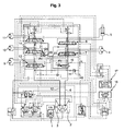
- a pipe layer having a swing speed adjustable system includes first and second variable displacement hydraulic pumps 2 and 3 connected to an engine 1; a left traveling motor 4 and a boom cylinder 5 connected to the first hydraulic pump 2; control valves 7 and 8 installed in a center bypass path 6 of the first hydraulic pump 2, and shifted to control the flow direction and flow amount of hydraulic fluid being supplied to the left traveling motor 4 and the boom cylinder 5; a right traveling motor 9, a swing motor 10, and a winch motor 11 connected to the second hydraulic pump 3; control valves 13, 14, and 15 installed in a center bypass path 12 of the second hydraulic pump 3, and shifted to control the flow direction and flow amount of hydraulic fluid being supplied to the right traveling motor 9, the swing motor 10, and the winch motor 11; a straight traveling valve 16 installed on an upstream side of the center bypass passage 6 of the first hydraulic pump 2, and shifted, in response to a signal pressure applied from an outside in a work mode for simultaneously driving a working device and a traveling device, to
- a backward flow prevention check valve 21 and a variable orifice 29 installed in an inlet-side flow path 19 of the swing motor control valve 14 to variably adjust a stroke of a poppet 24 so that the amount of hydraulic fluid being supplied to the swing motor 10 can be variably adjusted.
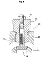
- the variable load-hold check valve 23 may include a valve seat 25 in which the inlet-side flow path 19 is formed; a backward flow prevention poppet 24 installed to open/close the inlet-side flow path 19; an adjustment block 26 screw-engaged with the valve seat 25 to press the poppet 24 so that the inlet-side flow path 19 is opened only in the case where the pressure in the flow path 19 exceeds a preset pressure; an elastic member (e.g. a compression coil spring) 27 installed between the poppet 24 and the adjustment block 26 to press the poppet 24 so that the poppet 24 is elastically biased in its initial state to block the inlet-side flow path 19; and an adjuster (e.g. a screw) 28 screw-engaged with the adjustment block 26 to variably adjust the stroke of the poppet 24 in accordance with its rotation direction.
- an elastic member e.g. a compression coil spring
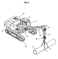
- a pipe layer on which a swing speed adjustable system is mounted includes a lower driving structure 30; an upper frame 33 mounted to swivel on the lower driving structure 30, and provided with a cab 31 and an engine room 32 mounted thereon; a boom 35 having a lower end part rotatably fixed to the upper frame 33, and rotated by the driving of a boom cylinder 34; a hook 38 ascending/descending by a wire rope 37 that is supported on a sheave 36 fixed to an upper part of the boom 35; and a winch 39 on which the wire rope 37 is wound.
- variable load-hold check valve 23 installed in the inlet-side flow path 19 of the swing motor control valve 14 to variably adjust the stroke of the poppet 24 so that the amount of hydraulic fluid being supplied to the swing motor 10 can be variably adjusted, is substantially the same as that as illustrated in FIG. 1 , the detailed description of the construction and operation thereof will be omitted.
- the same drawing reference numerals are used for the same elements across various figures.
- the pipe layer according to the present invention can be used as an excavator (in this case, attachments, such as a boom, an arm, and a bucket, are mounted thereon) or as the pipe layer (in this case, attachments, such as a boom, a hook, and a winch, are mounted thereon) in accordance with the work conditions.
- the maximum swing speed of the swing motor 10 can be adjusted by variably adjusting the amount of hydraulic fluid being supplied to the swing motor 10.
- the fully open area of the variable orifice 29 is reduced to reduce the amount of hydraulic fluid being supplied to the swing motor 10, and thus the maximum swing speed of the swing motor 10 can be reduced.
- variable orifice 29 is adjusted to increase the amount of hydraulic fluid being supplied to the swing motor 10.
- the fully open area of the variable orifice 29 is extended to increase the supply amount of hydraulic fluid to the swing motor 10. Accordingly, the maximum swing speed of the swing motor 10 is relatively increased in comparison to the swing speed of the pipe layer, and thus the work efficiency is improved.
- the pipe layer having a swing speed adjustable system can serve as an excavator or a pipe layer through replacement of attachments in accordance with work conditions.
- a quick swing speed is secured by increasing the amount of hydraulic fluid being supplied to the swing motor, and thus the work efficiency can be heightened.
Landscapes
- Engineering & Computer Science (AREA)
- Mechanical Engineering (AREA)
- Structural Engineering (AREA)
- Mining & Mineral Resources (AREA)
- Civil Engineering (AREA)
- General Engineering & Computer Science (AREA)
- Life Sciences & Earth Sciences (AREA)
- Agronomy & Crop Science (AREA)
- Automation & Control Theory (AREA)
- Fluid-Pressure Circuits (AREA)
- Operation Control Of Excavators (AREA)
- Jib Cranes (AREA)
- Component Parts Of Construction Machinery (AREA)
Applications Claiming Priority (1)
| Application Number | Priority Date | Filing Date | Title |
|---|---|---|---|
| KR1020080073282A KR20100012008A (ko) | 2008-07-26 | 2008-07-26 | 선회 속도 조정시스템이 구비된 파이프 레이어 |
Publications (1)
| Publication Number | Publication Date |
|---|---|
| EP2147886A2 true EP2147886A2 (de) | 2010-01-27 |
Family
ID=41111369
Family Applications (1)
| Application Number | Title | Priority Date | Filing Date |
|---|---|---|---|
| EP09009451A Withdrawn EP2147886A2 (de) | 2008-07-26 | 2009-07-21 | Rohrlegekran mit einem System zur Einstellung der Schwenkgeschwindigkeit. |
Country Status (5)
| Country | Link |
|---|---|
| US (1) | US20100018197A1 (de) |
| EP (1) | EP2147886A2 (de) |
| JP (1) | JP2010030781A (de) |
| KR (1) | KR20100012008A (de) |
| CN (1) | CN101634373A (de) |
Cited By (2)
| Publication number | Priority date | Publication date | Assignee | Title |
|---|---|---|---|---|
| EP2151526A1 (de) * | 2008-08-08 | 2010-02-10 | Volvo Construction Equipment Holding Sweden AB | Hydraulisches Durchflussverteilungssystem für Erd- und Rohrverlegungsarbeiten |
| EP2685110A4 (de) * | 2011-03-07 | 2015-09-02 | Volvo Constr Equip Ab | Hydraulischer kreislauf für rohrleitungsschicht |
Families Citing this family (6)
| Publication number | Priority date | Publication date | Assignee | Title |
|---|---|---|---|---|
| JP5397257B2 (ja) | 2010-02-16 | 2014-01-22 | 富士通株式会社 | 受信装置、及び受信方法 |
| CN102249163A (zh) * | 2011-07-20 | 2011-11-23 | 山河智能装备股份有限公司 | 一种卷扬助力装置 |
| JP5805581B2 (ja) * | 2012-04-23 | 2015-11-04 | 住友建機株式会社 | 建設機械の油圧回路及びその油圧制御装置 |
| KR101718836B1 (ko) * | 2012-08-16 | 2017-03-22 | 볼보 컨스트럭션 이큅먼트 에이비 | 건설기계용 유압 제어밸브 |
| CN108026713B (zh) * | 2015-09-16 | 2021-03-09 | 卡特彼勒Sarl | 液压作业机器的液压泵控制系统 |
| US10994778B2 (en) | 2018-12-20 | 2021-05-04 | Rce Equipment Solutions, Inc. | Tracked vehicle with steering compensation |
Family Cites Families (7)
| Publication number | Priority date | Publication date | Assignee | Title |
|---|---|---|---|---|
| US2622613A (en) * | 1947-06-02 | 1952-12-23 | Andale Co | Pressure control valve |
| KR100348128B1 (ko) * | 1994-09-30 | 2002-11-22 | 볼보 컨스트럭션 이키프먼트 홀딩 스웨덴 에이비 | 가변우선기능을갖는콘트롤밸브 |
| KR100797315B1 (ko) * | 2001-07-16 | 2008-01-23 | 두산인프라코어 주식회사 | 굴삭기의 주행 및 프론트작업의 복합작업용 유압제어장치 |
| KR100621985B1 (ko) * | 2005-08-02 | 2006-09-11 | 볼보 컨스트럭션 이키프먼트 홀딩 스웨덴 에이비 | 주행시스템 |
| KR100665113B1 (ko) * | 2005-12-09 | 2007-01-04 | 볼보 컨스트럭션 이키프먼트 홀딩 스웨덴 에이비 | 중장비의 유압회로 |
| KR100753986B1 (ko) * | 2006-04-18 | 2007-08-31 | 볼보 컨스트럭션 이키프먼트 홀딩 스웨덴 에이비 | 주행직진용 유압회로 |
| KR100753990B1 (ko) * | 2006-08-29 | 2007-08-31 | 볼보 컨스트럭션 이키프먼트 홀딩 스웨덴 에이비 | 주행직진용 유압회로 |
-
2008
- 2008-07-26 KR KR1020080073282A patent/KR20100012008A/ko not_active Ceased
-
2009
- 2009-07-21 EP EP09009451A patent/EP2147886A2/de not_active Withdrawn
- 2009-07-22 JP JP2009170899A patent/JP2010030781A/ja not_active Withdrawn
- 2009-07-23 US US12/507,867 patent/US20100018197A1/en not_active Abandoned
- 2009-07-24 CN CN200910161217A patent/CN101634373A/zh active Pending
Cited By (3)
| Publication number | Priority date | Publication date | Assignee | Title |
|---|---|---|---|---|
| EP2151526A1 (de) * | 2008-08-08 | 2010-02-10 | Volvo Construction Equipment Holding Sweden AB | Hydraulisches Durchflussverteilungssystem für Erd- und Rohrverlegungsarbeiten |
| EP2685110A4 (de) * | 2011-03-07 | 2015-09-02 | Volvo Constr Equip Ab | Hydraulischer kreislauf für rohrleitungsschicht |
| KR101820324B1 (ko) | 2011-03-07 | 2018-02-28 | 볼보 컨스트럭션 이큅먼트 에이비 | 파이프 레이어용 유압회로 |
Also Published As
| Publication number | Publication date |
|---|---|
| CN101634373A (zh) | 2010-01-27 |
| US20100018197A1 (en) | 2010-01-28 |
| KR20100012008A (ko) | 2010-02-04 |
| JP2010030781A (ja) | 2010-02-12 |
Similar Documents
| Publication | Publication Date | Title |
|---|---|---|
| US20100018197A1 (en) | Pipe layer having swing speed adjustable system | |
| US8424301B2 (en) | Hydraulic flow sharing system for excavating and pipe laying work | |
| US20160194851A1 (en) | Dredging arrangement for dredging material from an underwater bottom | |
| WO2006070501A1 (ja) | 建設機械の制御回路 | |
| CN113423900B (zh) | 工程机械 | |
| KR102456137B1 (ko) | 쇼벨 | |
| US20190194908A1 (en) | Construction Machine | |
| CN201382036Y (zh) | 多级速度控制阀组及应用该控制阀组的起重机 | |
| US10006472B2 (en) | Construction machine | |
| EP2672022B1 (de) | Hydraulischeflüssigkeitssteuerung für eine Arbeitsmaschine | |
| JP5442914B1 (ja) | パイプレイヤ | |
| JP5122906B2 (ja) | 建設機械のロードセンシング式油圧制御装置 | |
| CN101846108B (zh) | 多级速度控制阀组及应用该控制阀组的起重机 | |
| CN1688820A (zh) | 液压双回路系统 | |
| JP7674936B2 (ja) | 予備的保護のための油圧システムおよび作業機械 | |
| JP2001247293A (ja) | クレーンの油圧ウインチ回路 | |
| JP2015031377A (ja) | 油圧駆動装置 | |
| JP6759135B2 (ja) | 建設機械の油圧制御装置 | |
| JP2018172878A (ja) | 建設機械 | |
| JP6232347B2 (ja) | 作業機械 | |
| JP2813651B2 (ja) | バックホウの油圧回路構造 | |
| JPH0585697B2 (de) | ||
| KR20180111139A (ko) | 크레인 | |
| JPH0776859A (ja) | 建設機械の油圧駆動装置 | |
| JP2002285776A (ja) | アースドリル |
Legal Events
| Date | Code | Title | Description |
|---|---|---|---|
| PUAI | Public reference made under article 153(3) epc to a published international application that has entered the european phase |
Free format text: ORIGINAL CODE: 0009012 |
|
| AK | Designated contracting states |
Kind code of ref document: A2 Designated state(s): AT BE BG CH CY CZ DE DK EE ES FI FR GB GR HR HU IE IS IT LI LT LU LV MC MK MT NL NO PL PT RO SE SI SK SM TR |
|
| AX | Request for extension of the european patent |
Extension state: AL BA RS |
|
| STAA | Information on the status of an ep patent application or granted ep patent |
Free format text: STATUS: THE APPLICATION IS DEEMED TO BE WITHDRAWN |
|
| 18D | Application deemed to be withdrawn |
Effective date: 20140201 |