EP2146202A1 - Method and apparatus for detecting uneven surface defect - Google Patents
Method and apparatus for detecting uneven surface defect Download PDFInfo
- Publication number
- EP2146202A1 EP2146202A1 EP08792747A EP08792747A EP2146202A1 EP 2146202 A1 EP2146202 A1 EP 2146202A1 EP 08792747 A EP08792747 A EP 08792747A EP 08792747 A EP08792747 A EP 08792747A EP 2146202 A1 EP2146202 A1 EP 2146202A1
- Authority
- EP
- European Patent Office
- Prior art keywords
- concavo
- ferromagnetic metal
- detection method
- convex shape
- magnetic flux
- Prior art date
- Legal status (The legal status is an assumption and is not a legal conclusion. Google has not performed a legal analysis and makes no representation as to the accuracy of the status listed.)
- Granted
Links
- 230000007547 defect Effects 0.000 title claims abstract description 192
- 238000000034 method Methods 0.000 title claims description 69
- 230000005291 magnetic effect Effects 0.000 claims abstract description 106
- 238000001514 detection method Methods 0.000 claims abstract description 93
- 230000004907 flux Effects 0.000 claims abstract description 72
- 239000002184 metal Substances 0.000 claims abstract description 42
- 229910052751 metal Inorganic materials 0.000 claims abstract description 42
- 230000005294 ferromagnetic effect Effects 0.000 claims abstract description 40
- 230000008569 process Effects 0.000 claims description 36
- 238000005096 rolling process Methods 0.000 claims description 30
- 238000004519 manufacturing process Methods 0.000 claims description 27
- 238000000137 annealing Methods 0.000 claims description 16
- 230000000694 effects Effects 0.000 claims description 3
- 238000011144 upstream manufacturing Methods 0.000 claims description 2
- 229910000831 Steel Inorganic materials 0.000 description 71
- 239000010959 steel Substances 0.000 description 71
- 238000007689 inspection Methods 0.000 description 48
- 238000010586 diagram Methods 0.000 description 28
- 238000005259 measurement Methods 0.000 description 20
- XEEYBQQBJWHFJM-UHFFFAOYSA-N Iron Chemical compound [Fe] XEEYBQQBJWHFJM-UHFFFAOYSA-N 0.000 description 18
- 230000005415 magnetization Effects 0.000 description 18
- 238000012360 testing method Methods 0.000 description 14
- 230000008859 change Effects 0.000 description 10
- 229910052742 iron Inorganic materials 0.000 description 9
- 230000003746 surface roughness Effects 0.000 description 9
- 230000007423 decrease Effects 0.000 description 8
- 238000005516 engineering process Methods 0.000 description 7
- 238000005097 cold rolling Methods 0.000 description 6
- 230000035945 sensitivity Effects 0.000 description 6
- 230000015572 biosynthetic process Effects 0.000 description 5
- 230000009467 reduction Effects 0.000 description 5
- 238000011160 research Methods 0.000 description 5
- 229920006395 saturated elastomer Polymers 0.000 description 5
- 239000010960 cold rolled steel Substances 0.000 description 4
- 238000012546 transfer Methods 0.000 description 4
- OKTJSMMVPCPJKN-UHFFFAOYSA-N Carbon Chemical compound [C] OKTJSMMVPCPJKN-UHFFFAOYSA-N 0.000 description 3
- 238000002441 X-ray diffraction Methods 0.000 description 3
- 229910052799 carbon Inorganic materials 0.000 description 3
- 230000003247 decreasing effect Effects 0.000 description 3
- 238000011161 development Methods 0.000 description 3
- 238000007747 plating Methods 0.000 description 3
- 238000007670 refining Methods 0.000 description 3
- 238000013459 approach Methods 0.000 description 2
- 239000011248 coating agent Substances 0.000 description 2
- 238000011156 evaluation Methods 0.000 description 2
- 238000002474 experimental method Methods 0.000 description 2
- 238000005286 illumination Methods 0.000 description 2
- 239000006249 magnetic particle Substances 0.000 description 2
- 230000005389 magnetism Effects 0.000 description 2
- 238000003908 quality control method Methods 0.000 description 2
- 239000000758 substrate Substances 0.000 description 2
- 238000011179 visual inspection Methods 0.000 description 2
- 238000012935 Averaging Methods 0.000 description 1
- 241000238366 Cephalopoda Species 0.000 description 1
- 229910001335 Galvanized steel Inorganic materials 0.000 description 1
- 238000010420 art technique Methods 0.000 description 1
- LFYJSSARVMHQJB-QIXNEVBVSA-N bakuchiol Chemical compound CC(C)=CCC[C@@](C)(C=C)\C=C\C1=CC=C(O)C=C1 LFYJSSARVMHQJB-QIXNEVBVSA-N 0.000 description 1
- 238000004364 calculation method Methods 0.000 description 1
- 238000000576 coating method Methods 0.000 description 1
- 239000013078 crystal Substances 0.000 description 1
- 238000009826 distribution Methods 0.000 description 1
- 230000005284 excitation Effects 0.000 description 1
- 238000007716 flux method Methods 0.000 description 1
- 239000008397 galvanized steel Substances 0.000 description 1
- 238000010438 heat treatment Methods 0.000 description 1
- 230000006872 improvement Effects 0.000 description 1
- 230000003993 interaction Effects 0.000 description 1
- 239000000463 material Substances 0.000 description 1
- 239000000203 mixture Substances 0.000 description 1
- 230000003287 optical effect Effects 0.000 description 1
- 238000005457 optimization Methods 0.000 description 1
- 230000035699 permeability Effects 0.000 description 1
- 230000002265 prevention Effects 0.000 description 1
- 238000001953 recrystallisation Methods 0.000 description 1
- 239000010935 stainless steel Substances 0.000 description 1
- 229910001220 stainless steel Inorganic materials 0.000 description 1
- 230000001629 suppression Effects 0.000 description 1
- 238000004381 surface treatment Methods 0.000 description 1
- 230000001360 synchronised effect Effects 0.000 description 1
- 238000005496 tempering Methods 0.000 description 1
- 235000012431 wafers Nutrition 0.000 description 1
Images


Classifications
-
- G—PHYSICS
- G01—MEASURING; TESTING
- G01N—INVESTIGATING OR ANALYSING MATERIALS BY DETERMINING THEIR CHEMICAL OR PHYSICAL PROPERTIES
- G01N27/00—Investigating or analysing materials by the use of electric, electrochemical, or magnetic means
- G01N27/72—Investigating or analysing materials by the use of electric, electrochemical, or magnetic means by investigating magnetic variables
- G01N27/82—Investigating or analysing materials by the use of electric, electrochemical, or magnetic means by investigating magnetic variables for investigating the presence of flaws
-
- G—PHYSICS
- G01—MEASURING; TESTING
- G01B—MEASURING LENGTH, THICKNESS OR SIMILAR LINEAR DIMENSIONS; MEASURING ANGLES; MEASURING AREAS; MEASURING IRREGULARITIES OF SURFACES OR CONTOURS
- G01B7/00—Measuring arrangements characterised by the use of electric or magnetic techniques
- G01B7/34—Measuring arrangements characterised by the use of electric or magnetic techniques for measuring roughness or irregularity of surfaces
-
- G—PHYSICS
- G01—MEASURING; TESTING
- G01N—INVESTIGATING OR ANALYSING MATERIALS BY DETERMINING THEIR CHEMICAL OR PHYSICAL PROPERTIES
- G01N27/00—Investigating or analysing materials by the use of electric, electrochemical, or magnetic means
- G01N27/72—Investigating or analysing materials by the use of electric, electrochemical, or magnetic means by investigating magnetic variables
- G01N27/82—Investigating or analysing materials by the use of electric, electrochemical, or magnetic means by investigating magnetic variables for investigating the presence of flaws
- G01N27/83—Investigating or analysing materials by the use of electric, electrochemical, or magnetic means by investigating magnetic variables for investigating the presence of flaws by investigating stray magnetic fields
Definitions
- the present invention relates to a method and an apparatus for detecting concavo-convex shape surface defects existing on a ferromagnetic metal, and in particular to a method and an apparatus for detecting concavo-convex shape surface defects, wherein the concavo-convex shape surface defects each have a concavo-convex level in the range of 0.5 to 6 ⁇ m and an area of 10 mm 2 or larger and exist on a rough surface, with Ra being in the range of 0.5 to 2 ⁇ m, of a steel sheet having a thickness in the range of 0.4 to 2.3 mm.
- FIG. 4 is a schematic diagram of a cross-section of a fine concavo-convex shape surface defect. The size of each fine concavo-convex shape surface defect is approximately in the range of 10 to 1000 mm 2 in area, but is 5 ⁇ m or lower in concavo-convex level as described above. The lowest concavo-convex level is approximately 1 ⁇ m, which is very small and is of the same order as the surface roughness.
- the shape of fine concavo-convex shape surface defects includes point flaws like roll-generated flaws described earlier and flaws extending in the longitudinal direction of a steel sheet, such as linear marks or buckling marks.
- Patent Document 1 is a technique for inspecting a mirror surface, and thus cannot be applied to an object with a large surface roughness because of the problem that beams converging into or diffused from concaves and convexes of flaws are masked by beams diffused by surface roughness and thus the flaws cannot be detected.
- Patent Document 2 is intended for steel sheets, but still cannot be applied to objects other than materials having a mirror surface such as stainless steel sheets. Furthermore, this technique is admittedly effective in detecting concavo-convex defects extending perpendicular to the illumination detection, but is insufficient in terms of detection sensitivity for those extending parallel to the illumination detection.
- Patent Document 3 is intended for unpolished wafers having rough surfaces, but still has the problem of low detection accuracy because it determines whether a flaw is present on the basis of the total light intensity and thus cannot detect specific signals of individual flaws.
- Patent Document 4 The technique disclosed in Patent Document 4 was developed to address this situation, and accordingly an apparatus for this technique has very high detection sensitivity.
- this technique requires an angle of incidence as large as close to 90°, thereby making it difficult to introduce a necessary apparatus into an actual operation line. It has also the problem that adjustment of optics is difficult.
- the intensity of signals for this magnetic flux leakage inspection corresponds to the shape change level of surface defects (concavo-convex change level), and thus the lowest shape change level of surface defects (concavo-convex change level) detectable in an automatic inspection is limited.
- this lower limit to be approximately 100 ⁇ m (Non-patent Document 1).
- Non-patent Document 1 it is recognized that stable detection of surface defects having a shape change level of approximately 100 ⁇ m or lower is difficult and signals generated by changes in the shape of approximately 100 ⁇ m or lower serve only as noise sources observed in flaw detection for other purposes (e.g., detection of inclusions).
- the lowest detectable size of an inclusion in a steel sheet discussed in the present invention whose maximum thickness is 2.3 mm, would probably be much larger than 10 ⁇ m (size in the direction of the steel sheet thickness) if they can be detected at all, considering the fact that this inclusion detector is intended for thinner steel sheets used for cans.
- Non-patent Document 6 discloses the results of explorative research on the detection of whetstone-inspection-level flaws conducted by WG for research on cold rolling in rolling, refining, and temper systems, Iron and Steel Technology Committee, the Japan Iron and Steel Federation from September 1994 to July 1995 (Report of Explorative Research on Seed Technology for Detection of Whetstone-inspection-level Flaws).
- Previous approaches to automatic inspections of fine concavo-convex shape surface defects, the target of the present invention were mainly based on a light-detecting method, and, to date, there have been no approaches using a magnetic flux leakage inspection method.
- the present invention provides a practical method for stable detection of concavo-convex shape surface defects that exist on a test object having a surface roughness Ra approximately in the range of 0.5 to 2 ⁇ m, wherein the concavo-convex shape surface defects are usually almost invisible and detectable only by whetstone inspection, are difficult to detect by automatic detection, and each have a concavo-convex level on the order of a few micrometers, and also provides an apparatus for the same objective.
- the present invention allows for stable detection of fine concavo-convex shape surface defects that exist on a test object having considerable surface roughness, wherein the fine concavo-convex shape surface defects are usually almost invisible to the naked eye and detectable only by whetstone inspection, are difficult to detect in automatic detection, and each have a concavo-convex level on the order of a few micrometers and a smooth outline.
- the inventors To measure fine concavo-convex shape surface defects generated during rolling (roll-generated fine concavo-convex shape surface defects), i.e., the target of the present invention, the inventors first conducted X-ray diffraction analysis of such defects in some sheets to determine the physical characteristics of the defects. As a result, it was found that these fine concavo-convex shape surface defects had strain that probably emerged during transfer of flaws from the roll in the process of defect formation.
- FIGs. 2 are diagrams showing example results of magnetic flux leakage inspection and shape measurement obtained before and after annealing.
- FIGs. 2 had a concavo-convex level of 5 ⁇ m, which was slightly larger than the minimum detectable size of a fine concavo-convex shape surface defect.
- FIGs. 2A and 2B represent the state before annealing
- FIGs. 2C and 2D represent the state after annealing.
- FIGs. 2A and 2C represent the shape distribution in the longitudinal direction (traveling direction)
- FIGs. 2B and 2D represent the values of signals sensed by the magnetic flux leakage inspection apparatus in the longitudinal direction (traveling direction).
- the strain level measured using X-ray diffraction decreased from 0.00217 to 0.00067 during annealing. The results shown in FIGs.
- FIG. 3 is a diagram showing the relationship between strain and leakage flux, which was obtained by plotting the strain measured using X-ray diffraction in some roll-generated fine concavo-convex shape surface defects whose concavo-convex levels were almost identical against the results of magnetic flux leakage inspection.
- FIG. 3 demonstrates the strong relationship between the strain and the leakage flux signals, and this result also shows that the strain can be detected using leakage flux.
- strain generates leakage flux signals, and this is probably because strain changes the crystal lattice interval in the sample and accordingly changes the interaction between spins, thereby changing the magnetic characteristics of the sample.
- a usual magnetic flux leakage inspection method generally uses a saturated magnetic flux for measurement to improve the signal intensity and remove the influence of noise generated by unevenness of magnetic characteristics (magnetic permeability) of the test object.
- the measurement of roll-generated fine concavo-convex shape surface defects involves measurement of signals attributed to strain, and sensitive measurement of such signals can be more easily achieved by using magnetization levels lower than saturated magnetization.
- the intensity of a magnetic field applied to a sample described herein means not the total magnetic field generated by a magnetizer for magnetization of the sample, but also the magnetic field directly applied to the test site of the sample, i.e., the quantity corresponding to H in a B-H curve obtained in the test site of the sample.
- Such a magnetic flux leakage inspection apparatus is usually used for product inspections in a final line, so that there are various processes between occurrences of defects and detection of them. These processes include, for example, a step wherein the steel sheet is released from strain, which emerges during the formation of defects, through the removal of the strain by heat, the release of strain by means of another stress such as tension applied during threading, or other circumstances. In such a process, detection of signals attributed to strain may be impossible. Therefore, the location where the detection is performed should be discussed.
- FIG. 8 is a schematic diagram of example manufacturing processes of cold rolled steel sheets.
- Major manufacturing processes of cold rolled steel sheets include cold rolling and subsequent annealing and temper rolling.
- roll-generated fine concavo-convex shape surface defects are generated by a mill roll used for cold rolling, a roll installed in an annealing furnace for the annealing process subsequent to cold rolling, or a temper roll used after the annealing process.
- Manufacturing processes of cold rolled steel sheets usually include a thermal process, such as an annealing process, to remove the influence of hardening that occurs during rolling.
- This thermal process sometimes involves a temperature increase to recrystallization temperature. Heating a steel sheet in this thermal process may result in the suppression of defect signals as with the experiment described earlier. Therefore, measurement should be carried out at a point just after rolling that causes defects, like "Position A" in FIG. 8 , or at a point between rolling that causes defects and a thermal process that gives a sufficient amount of heat to release strain (a process producing an annealing effect), like "Position B.”
- a preferred point to carry out the measurement is a point after temper rolling. Furthermore, a point just after temper rolling, "Position C" in FIG. 8 , is the most preferable because at this point feedback and location tracking in the event of defects are easy and the strain condition of a steel sheet may be changed before this point by tension applied while the sheet is threading through the manufacturing line.
- a manufacturing process of surface-treated steel sheets such as galvanized steel sheets and tinned steel sheets manufactured using CGL, EGL, or other lines, basically includes the same processes until temper rolling although the manufacturing process further includes a plating process or other surface treatment processes. Therefore, the preferred point of such measurement is the same as that described above.
- defects that transfer concaves and convexes to the plated layer on the surface without affecting the substrate metal may occur.
- Such defects can be better detected after strain is given to the substrate metal by temper rolling, and thus a method wherein the measurement is carried out after temper rolling is especially preferable in this case.
- FIG. 1 is a diagram showing an illustrative configuration of an apparatus according to an example of the present invention.
- 1 represents a steel sheet
- 2 represents a roller-generated fine concavo-convex shape surface defect
- 3 represents a direct current power source
- 4 represents a magnetizer
- 5 represents a magnetic sensor
- 6 represents an amplifier
- 7 represents a filter circuit
- 8 represents a defect analyzer
- 9 represents a roller-generated fine concavo-convex shape surface defect detector.
- the steel sheet 1 has a roller-generated fine concavo-convex shape surface defect 2 having a level in the thickness direction of a few micrometers, which is equivalent to the level of roughness.
- the roller-generated fine concavo-convex shape surface defect detector 9 is placed by the steel sheet 1, and the detector is configured as follows: the magnetizer 4 and the magnetic sensor 5 are arranged on the same side facing the steel sheet 1; the magnetizer 4 magnetizes the steel sheet 1 using direct current supplied by the magnetization power source 3.
- Magnetic flux generated between both magnetic poles by the magnetizer 4 passes through the steel sheet 1. If a defect 2 exists on the steel sheet 1, strain that emerges during the formation of the defect 2 and surrounds the defect 2 interrupts the magnetic flux, and then the change in the magnetic flux can be detected by the magnetic sensor 5.
- the signal output from the magnetic sensor 5 is amplified by the amplifier 6, and then noise contained therein is removed by the filter circuit 7. After that, the defect analyzer 8 determines the point that corresponds to a signal having intensity equal to or higher than a threshold value to be a defect.
- this example uses a direct current signal for magnetic flux leakage inspection, an alternating current signal may be used instead.
- a synchronous detection circuit is required.
- the magnetizer and the magnetic sensor are arranged on the same side facing the steel sheet; however, if a direct current signal is used, they may be arranged on opposite sides across the steel sheet, and even if an alternating current is used, they may be arranged in the same way, on opposite sides across the steel sheet, as long as the excitation frequency is sufficiently low for the sheet thickness.
- the defect analyzer 9 uses the intensity of a signal attributed to a defect for determination of the defect
- the length, width, or area of a point that gives a signal having an intensity equal to or higher than a threshold value may be used for determination together with the signal intensity, and two or more of them may also be used in combination for determination.
- the phase of alternating current may be used for determination in the case where alternating current is used.
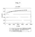
- the inventors measured B-H curves for some steels with different compositions. The result is shown in FIG. 7 .
- This drawing includes B-H curves obtained for three steels with different C%, and A represents steel with very low carbon content (C%: 0.0 to 0.002), B represents steel with low carbon content (C%: 0.03 to 0.06), and C represents enameled steel (C%: approximately 0.0009). From the results, no difference due to the kind of steel was observed between B-H curves. After that, the inventors examined these steels for roll-generated fine concavo-convex shape surface defects. A representative result (very low carbon content) is described below.
- FIGs. 5 are diagrams showing a comparison between a strong magnetization condition and a weak magnetization condition, and represent examples of flaw detection for roll-generated fine concavo-convex shape surface defects under the strong magnetization condition (48000 A/m) and the weak magnetization condition (8000 A/m). It can be seen that the signal intensity was reduced. Similar measurement was repeated with different magnetic field intensities, and the obtained signal level, noise level, and S/N were plotted against the magnetic field intensity, as shown in FIG. 6 .
- a magnetic field of at least 4000 A/m and less than 25000 A/m gave as high S/N as 5 or higher, and thus is suitable for detection.
- this magnetic field has a magnetic flux density corresponding to 75 to 95% of that in the saturated magnetization state, as shown in FIG. 7 .
- a magnetic field of 25000 A/m or higher, in particular, higher than 40000 A/m resulted in an increased signal intensity (however, the noise level also increased and thus an increase in S/N was slight). This is probably because the signal component attributed to concaves and convexes of defects was increased.
- conventionally used measurement at the saturated magnetization level is preferable.
- the magnetic flux density resulting in a magnetic field of 25000 A/m or higher corresponds to 95% or higher of that in the saturated magnetization state as shown in FIG. 7 .
- 40000 A/m or higher corresponds to 99%.
- concaves and convexes are present although they are as fine as a few micrometers at minimum, and thus such signals attributed to concaves and convexes can be obtained as well. Therefore, the following two conditions for flaw detection can be combined to improve the sensitivity for detecting defects: flaw detection at a magnetic field intensity less than 25000 A/m for sensing signals attributed to strain; flaw detection at a magnetic field intensity of 25000 A/m or higher for sensing signals attributed to concaves and convexes.
- comparing the signal component attributed to concaves and convexes with that attributed to strain enables comparing of the concavo-convex level and the strain level, thereby making it possible to identify which roll causes defects by, for example, assuming that the combination of a low concavo-convex level and large strain represents a defect caused by a roll used at a high rolling reduction.
- the value of magnetic flux density was calculated from a magnetic field intensity on the basis of a predetermined B-H curve.
- the value of a magnetic field intensity for this calculation may be measured in the vicinity of the test site of a sample.
- leakage flux based on direct current for measurement a leakage flux method based on alternating current, an eddy current inspection method, or a magnetic particle inspection method may be used instead as long as the method allows for sensing of signals attributed to strain.
- this example used a hall element as the magnetic sensor, a coil, a magnetic resistance element, or a SQUID may be used instead as long as the element can sense magnetism.
- a single magnetic sensor or a plurality of magnetic sensors may be used. If plurality of magnetic sensors are used, a wider area can be simultaneously measured by arranging the magnetic sensors in the direction perpendicular to the traveling direction of the sample and parallel to the sample itself.
- a too large pitch of magnetic sensors would cause overlooking of defects passing between the magnetic sensors, whereas a too small pitch would reduce the efficiency.
- a pitch of magnetic sensors in the range of 0.5 to 3 mm is enough for detection, one in the range of 0.8 to 2 mm is the most preferable for sufficient detection sensitivity and efficiency.
- the lift-off used in this example was 1 mm, and this value was chosen on the basis of the following findings. Especially small ones of roll-generated fine concavo-convex shape surface defects sometimes give very slight leakage flux signals. To detect such defects, optimization of the lift-off, which is a distance between a sensor and a sample, is required in addition to the measures described earlier.
- defects necessitating whetstone inspection for detection thereof in an iron and steel manufacturing line are, as described earlier, those each having concaves and convexes equivalent to roughness (approximately a few micrometers) and a radius of curvature R of 10 mm or larger and thus masked by roughness of a few micrometers.
- Such defects often each have a diameter approximately in the range of 4 to 30 mm and an area approximately in the range of 10 to 1000 mm 2 on the surface of a steel sheet.
- a smaller lift-off results in a higher sensitivity and thus is more advantageous.
- FIG. 9 is a diagram showing Example Relationship 1 between the lift-off and S/N
- FIG. 10 is a diagram showing Example Relationship 2 between the lift-off and S/N.
- Each of these drawings is a graph made for the purpose of studying the relationship between the lift-off and S/N.
- FIG. 9 shows the results obtained by measuring the following sample defects each having a relatively small concavo-convex level of a few micrometers and a large area, the main target of detection according to the present invention, using different lift-offs: Sample a: 15 mm in length, 4 mm in width; Sample b: 10 mm in length, 4 mm in width.
- FIG. 9 shows the results obtained by measuring the following sample defects each having a relatively small concavo-convex level of a few micrometers and a large area, the main target of detection according to the present invention, using different lift-offs: Sample a: 15 mm in length, 4 mm in width; Sample b: 10 mm in length, 4 mm
- Sample 10 shows the results obtained by measuring the following sample defects each having a relatively large concavo-convex level of a few tens of micrometers and a small area: Sample c: 1 mm in length, 2 mm in width; Sample d: 1 mm in length, 2 mm in width.
- a hall element with the area of magnetism-sensing portion being approximately 0.2 mm or smaller in diameter was used as the sensor.
- a lift-off in the range of 0.5 to 1.5 mm gave S/N of 2 or higher and thus is sufficient to be used for detection; however, considering the long and short dashed line representing S/N of 3, the level allowing for automatic detection, a preferred lift-off range for automatic detection is 0.8 to 1.2 mm.
- a lift-off of 1 mm gave especially high S/N and this suggests that the most preferred lift-off range is 0.9 to 1.1 mm.
- FIGs. 11 are schematic diagrams showing the situations of measurement of small defects (corresponding to the defects c and d described above) and large defects (corresponding to the defects a and b described above).
- a defect difficult to detect is one having small concaves and convexes and a small area.
- Such a defect is inherently smaller than the detection area of a sensor, and thus the area of the defect encompassed in the detection area of the sensor decreases as the lift-off is increased (see FIG. 11A ).
- signals existing in the detection area are averaged during detection, and thus the defect signals are averaged together with signals coming from the surrounding normal portion (background noise signals). Therefore, the signal intensity is further lowered.
- signals coming from such a normal portion have almost identical intensities, and thus a decrease in these signals is smaller than that in defect signals.
- defects to be measured by the present invention have a very small concavo-convex level and a large area (corresponding to 5 mm or larger in diameter). Also in detection of such a defect, the defect signal and the noise signal coming from a sample itself decrease together as the lift-off is increased; however, a larger lift-off does not lead to a weaker defect signal because the size of the defect is large and thus the area of the defect encompassed in the detection area of a sensor remains constant until the detection area of the sensor exceeds that of the defect even if the lift-off is increased (see FIG. 11B ).
- the random noise component decreases as a result of arithmetic averaging until the lift-off is increased to some extent. Therefore, because of the relationship between the size of the defect and the arithmetic average of random noise, S/N virtually increases until the lift-off-reaches a certain value. Further increasing the lift-off would lead to a more significant decrease in the defect signal as with the case of a small defect, thereby probably causing S/N to decrease.
- whetstone inspection usually performed in an iron and steel manufacturing line involves rasping such defects as described above, which each have a concavo-convex level of a few micrometers and a size approximately in the range of 5 to 30 mm in diameter on a steel sheet, with a whetstone to make them visible, but this inspection often further includes inspection of fine defects that can be detected without being rasped with a whetstone. Such defects can be detected without being rasped with a whetstone and thus the present invention does not handle them.
- FIGs. 12 are diagrams each showing the shapes of the sample defects used for evaluation of the present invention.
- FIG. 12A is a diagram showing the sizes of almost invisible defects in the direction of steel sheet thickness (concavo-convex change level) and the incidence thereof (the number of samples)
- FIG. 12B is a diagram showing the areas of the defects on the steel sheet and the incidence thereof (the number of samples).
- the present invention handles fine concavo-convex shape surface defects each having a concavo-convex level (shape change level in the direction of steel sheet thickness) in the range of 0.5 to 6 ⁇ m and an area approximately in the range of 10 to 1000 mm 2 (corresponding to 4 to 30 mm in diameter) on a steel sheet.
- these defects existed on steel sheets each having a thickness in the range of 0.4 to 2.3 mm and surface roughness Ra in the range of 0.5 to 2 ⁇ m, and the radius of curvature R was 10 mm or larger on the cross-section in the direction of steel sheet thickness.
- FIG. 13 is a diagram showing the relationship between the size of the defects shown in FIG. 12A in the thickness direction and S/N of leakage flux signals.
- S/N of leakage flux signals is 2 or higher for all defects, and this demonstrates that the present invention has a sufficient detection sensitivity.
- four sample defects having a size in the concavo-convex direction (concavo-convex change level) of 0.5 ⁇ m showed S/N of approximately 3 and thus the data points for these defects are plotted overlapping each other.
- FIG. 14 is a diagram showing the relationship between the size of defects in the thickness direction and the thickness of the test steel sheets.
- the data points measured according to the present invention and shown in FIGs. 12 and 13 are represented by O, and those measured using a known magnetic flux leakage inspection method using a magnetic flux leakage inspection apparatus for steel sheets installed in a line after a cold rolling process are represented by x.
- x those measured using a known magnetic flux leakage inspection method using a magnetic flux leakage inspection apparatus for steel sheets installed in a line after a cold rolling process.
- the value s/t obtained by dividing the size of a test defect in the thickness direction s (unit: ⁇ m) by the thickness of a test sheet t (mm) is large and approximately in the range of 40 to 250 in a known magnetic flux leakage inspection method, whereas the same value is very small in the present invention, data points obtained in accordance with which are represented by ⁇ . Then, an enlarged view of FIG. 14 with the range of the vertical axis being 0 to 10 ⁇ m and the range of the horizontal axis being 0 to 1.5 mm is shown in FIG. 15 .
- the present invention handles fine concavo-convex shape surface defects existing on a steel sheet with a thickness in the range of 0.4 to 2.3 mm and each having a concavo-convex level of 0.5 to 6 ⁇ m and, in the present invention, the value s/t obtained by dividing the size of a defect in the direction of steel sheet thickness s (concavo-convex change level; unit: ⁇ m) by the thickness of a test sheet t (mm) is extremely small and in the range of 0.63 to 9.0 as can be seen in FIG. 15 .
- the target of inspection according to the present invention is fine concavo-convex shape surface defects having s/t, the ratio of the size of a defect in the direction of steel sheet thickness s ( ⁇ m) to the steel sheet thickness (mm), in the range of 0.63 to 9.0.
Abstract
Description
- The present invention relates to a method and an apparatus for detecting concavo-convex shape surface defects existing on a ferromagnetic metal, and in particular to a method and an apparatus for detecting concavo-convex shape surface defects, wherein the concavo-convex shape surface defects each have a concavo-convex level in the range of 0.5 to 6 µm and an area of 10 mm2 or larger and exist on a rough surface, with Ra being in the range of 0.5 to 2 µm, of a steel sheet having a thickness in the range of 0.4 to 2.3 mm.
- In a manufacturing process of a ferromagnetic metal, in particular, thin steel sheets, foreign matter adhering to or caught up in a roll installed in a manufacturing line sometimes produces concavo-convex shape on the roll itself, and this concavo-convex shape may be transferred to resulting steel sheets as roll-generated flaws.
- Such roll-generated defects include concavo-convex shape surface defects that each exist on a rough steel sheet surface (Ra = 0.5 to 2 µm) and have a smooth outline (radius of curvature R ≥ 10 mm), a concavo-convex level of 5 µm or lower, and an area of 10 mm2 or larger. Such defects are hereinafter referred to as fine concavo-convex shape surface defects.
FIG. 4 is a schematic diagram of a cross-section of a fine concavo-convex shape surface defect. The size of each fine concavo-convex shape surface defect is approximately in the range of 10 to 1000 mm2 in area, but is 5 µm or lower in concavo-convex level as described above. The lowest concavo-convex level is approximately 1 µm, which is very small and is of the same order as the surface roughness. - Most of roll-generated defects have a relatively high concavo-convex level and are visible, and thus they can be easily found in the course of a manufacturing line. However, such fine concavo-convex shape surface defects have concavo-convex levels as small as the surface roughness of steel sheets. The optical difference between these fine defects and surface roughness is small, and thus the defects cannot be easily found in the course of a manufacturing line when observed without any treatment. However, once the surface is coated and the surface roughness is filled with a coating agent to make a smooth surface, the fine defects become clearly visible thereby posing serious problems in terms of appearance. Therefore, detection of fine concavo-convex shape surface defects prior to coating is an important issue in quality control.
- The shape of fine concavo-convex shape surface defects includes point flaws like roll-generated flaws described earlier and flaws extending in the longitudinal direction of a steel sheet, such as linear marks or buckling marks.
- Such fine concavo-convex shape surface defects are formed by transfer of concavo-convex shape of a roll to a steel sheet, and this situation persists until the roll is replaced or the process is improved. Therefore, early detection and countermeasures are very important also for yield improvement.
- To find such fine concavo-convex shape surface defects, threading of steel sheets is stopped during operations in each inspection line in an iron-making process, and thereafter inspectors rasp all the coils with a whetstone and perform visual inspections thereof. After being rasped with a whetstone, convex portions, which are more strongly rasped than concave portions, have a higher reflectance than concave portions. This makes the difference between convex and concave portions clearer and more visible in visual inspections. This method is called whetstone inspection.
- Unfortunately, this method necessitates stopping of inspection lines and requires a substantial period of time, thereby reducing the efficiency of operations. To address this situation, a method for automatically inspecting concavo-convex shape defects each having a concavo-convex level on the order of a few micrometers and a smooth outline has been developed. Examples of such an automatic surface analyzer may include the techniques disclosed in
Patent Documents - However, the technique disclosed in
Patent Document 1 is a technique for inspecting a mirror surface, and thus cannot be applied to an object with a large surface roughness because of the problem that beams converging into or diffused from concaves and convexes of flaws are masked by beams diffused by surface roughness and thus the flaws cannot be detected. - Also, the technique disclosed in
Patent Document 2 is intended for steel sheets, but still cannot be applied to objects other than materials having a mirror surface such as stainless steel sheets. Furthermore, this technique is admittedly effective in detecting concavo-convex defects extending perpendicular to the illumination detection, but is insufficient in terms of detection sensitivity for those extending parallel to the illumination detection. - Additionally, the technique disclosed in
Patent Document 3 is intended for unpolished wafers having rough surfaces, but still has the problem of low detection accuracy because it determines whether a flaw is present on the basis of the total light intensity and thus cannot detect specific signals of individual flaws. - The technique disclosed in
Patent Document 4 was developed to address this situation, and accordingly an apparatus for this technique has very high detection sensitivity. However, this technique requires an angle of incidence as large as close to 90°, thereby making it difficult to introduce a necessary apparatus into an actual operation line. It has also the problem that adjustment of optics is difficult. - In view of general defect-detecting methods without limiting the target thereof to fine concavo-convex shape surface defects, there are detection methods wherein magnetic flux is applied to a sample, for example, the technique disclosed in
Patent Document 5 for detecting an inclusion existing inside an object using a magnetic flux leakage inspection method. This patent document describes that surface defects can be detected also by using this magnetic flux leakage inspection method in the form of leakage flux signals generated by changes in the surface shape (signals generated by variation or disturbance of magnetic flux due to changes in the shape). - However, the intensity of signals for this magnetic flux leakage inspection corresponds to the shape change level of surface defects (concavo-convex change level), and thus the lowest shape change level of surface defects (concavo-convex change level) detectable in an automatic inspection is limited. Those skilled in the art consider this lower limit to be approximately 100 µm (Non-patent Document 1). In other words, it is recognized that stable detection of surface defects having a shape change level of approximately 100 µm or lower is difficult and signals generated by changes in the shape of approximately 100 µm or lower serve only as noise sources observed in flaw detection for other purposes (e.g., detection of inclusions).
- Although such a simple comparison may be inapplicable, signals for detecting inclusions similarly correspond to the size of defects, and thus the lowest detectable size of a defect in the thickness direction of the test steel sheet is still limited. Those skilled in the art consider this lower limit to be approximately 10 µm (Non-patent
Documents 2 to 5). - Furthermore, in such magnetic flux leakage inspection, an increase in the sheet thickness would result in a widened range of flaw detection in the thickness direction, thereby resulting in increased background noise generated by the steel sheet, increased magnetizing force being needed for magnetization of the steel sheet, reduced flatness of the surface of the steel sheet leading to difficulty in scanning the steel sheet with a sensor, and other problems. For these reasons, the thicker the test sheet is, the more difficult flaw detection is. With the inclusion detector described in the non-patent documents listed above, the lowest detectable size of an inclusion in a steel sheet discussed in the present invention, whose maximum thickness is 2.3 mm, would probably be much larger than 10 µm (size in the direction of the steel sheet thickness) if they can be detected at all, considering the fact that this inclusion detector is intended for thinner steel sheets used for cans.
- Meanwhile, Non-patent
Document 6 discloses the results of explorative research on the detection of whetstone-inspection-level flaws conducted by WG for research on cold rolling in rolling, refining, and temper systems, Iron and Steel Technology Committee, the Japan Iron and Steel Federation from September 1994 to July 1995 (Report of Explorative Research on Seed Technology for Detection of Whetstone-inspection-level Flaws). Previous approaches to automatic inspections of fine concavo-convex shape surface defects, the target of the present invention, were mainly based on a light-detecting method, and, to date, there have been no approaches using a magnetic flux leakage inspection method. - Therefore, it can be said that the use of magnetic flux leakage inspection for detecting fine concavo-convex shape surface defects that can be visible only after the surface of a test steel sheet is rasped with a whetstone, the target of the present invention, would not normally be considered by those skilled in the art of magnetic flux leakage inspection.
- Patent Document 1: Japanese Unexamined Patent Application Publication No.
S58-86408 - Patent Document 2: Japanese Unexamined Patent Application Publication No.
H5-256630 - Patent Document 3: Japanese Unexamined Patent Application Publication No.
H6-58743 - Patent Document 4: Japanese Unexamined Patent Application Publication No.
2000-298102 - Patent Document 5: Japanese Unexamined Patent Application Publication No.
H8-160006 - Non-patent Document 1: Magnetic Flux Leakage Inspection Method for Iron and Steel Products, February 28, 2001, NDI Department (Technology and Technique Transfer Committee), Working Group for Quality Control, the Iron and Steel Institute of Japan
- Non-patent Document 2: Development of a Minute Inclusion Detector for Thin Steel Strips, CAMP-ISIJ, Vol. 10 (1997)-289
- Non-patent Document 3: Development of Gouge Defect Detector, Chiba 2CGL, 131st Control Technology Working Group Meeting, Manufacturing Technology Department, the Iron and Steel Institute of Japan
- Non-patent Document 4: Development of Non-metallic Inclusion On-line Detection System, CAMP-ISIJ, Vol. 7 (1994)-1270
- Non-patent Document 5: State-of-the-art Techniques for Internal Quality Measurements in Steel Sheets Production Processes, Kawasaki Steel Giho, 31 1999 4.211-215
- Non-patent Document 6: Report of Explorative Research on Seed Technology for Detection of Whetstone-inspection-level Flaws, July 1995, WG for research on cold rolling in rolling, refining, and temper systems, Iron and Steel Technology Committee, the Japan Iron and Steel Federation
- The present invention provides a practical method for stable detection of concavo-convex shape surface defects that exist on a test object having a surface roughness Ra approximately in the range of 0.5 to 2 µm, wherein the concavo-convex shape surface defects are usually almost invisible and detectable only by whetstone inspection, are difficult to detect by automatic detection, and each have a concavo-convex level on the order of a few micrometers, and also provides an apparatus for the same objective.
- The present invention was completed on the basis of the findings described above, and a summary thereof is as follows.
- [1] A detection method for detecting a concavo-convex shape surface defect existing on a ferromagnetic metal, including a step of sensing a signal attributed to strain of the concavo-convex shape surface defect having a size in a range of 0.5 to 6 µm.
- [2] The detection method according to [1], wherein a thickness of the ferromagnetic metal is in a range of 0.4 to 2.3 mm.
- [3] The detection method according to [1], wherein a ratio s/t of a size of the concavo-convex shape surface defect in a direction of a thickness s (µm) to the thickness of the ferromagnetic metal t (mm) is in a range of 0.63 to 9.0.
- [4] The detection method according to [1], wherein the signal is magnetic flux leaking from the ferromagnetic metal to which magnetic flux is applied.
- [5] The detection method according to [4], wherein a magnetic flux density of the ferromagnetic metal to which the magnetic flux is applied is at least 75% and lower than 95% of the magnetic flux density at magnetic saturation.
- [6] The detection method according to [4], wherein the sensing is performed under combined conditions including a condition under which the magnetic flux density of the ferromagnetic metal to which the magnetic flux is applied is at least 75% and lower than 95% of the magnetic flux density at magnetic saturation and another condition under which it is at least 95% of the magnetic flux density at magnetic saturation.
- [7] The detection method according to [4], wherein the intensity of a magnetic field applied to the ferromagnetic metal is at least 4000 A/m and less than 25000 A/m.
- [8] The detection method according to [4], wherein the sensing is performed under a combined condition obtained by combining a condition under which the intensity of a magnetic field applied to the ferromagnetic metal is at least 4000 A/m and less than 25000 A/m and another condition under which it is at least 25000 A/m.
- [9] The detection method according to [1], wherein a distance between the ferromagnetic metal and a sensing apparatus that senses the signal is in a range of 0.5 to 1.5 mm.
- [10] The detection method according to any one of [1] to [9], wherein the signal is a physical quantity attributed to strain of the concavo-convex shape surface defect occurring in a process that is a process downstream of rolling, which is a cause of the defect, and also is a process upstream of a process producing an annealing effect.
- [11] The detection method according to any one of [1] to [9], wherein the signal is a physical quantity attributed to strain of the concavo-convex shape surface defect occurring in a process that is a process downstream of rolling, which is a cause of the defect, and comes later than temper rolling.
- [12] A detection method for detecting a fine concavo-convex shape surface defect that has a concavo-convex level in a range of 0.5 to 6 µm and exists on a ferromagnetic metal sample including a step of detecting the surface defect by sensing a signal attributed to strain of a defect portion of the sample.
- [13] A manufacturing method for manufacturing a ferromagnetic metal including the detection method according to any one of [1] to [9].
- [14] A manufacturing method for manufacturing a ferromagnetic metal including the detection method according to [10].
- [15] A manufacturing method for manufacturing a ferromagnetic metal including the detection method according to [11].
- [16] A detecting apparatus for detecting a fine concavo-convex shape surface defect that has a concavo-convex level in a range of 0.5 to 6 µm and exists on a ferromagnetic metal sample, including means for detecting the surface defect by sensing a signal attributed to strain of a defect portion of the sample.
- [17] A detecting apparatus for detecting a concavo-convex shape surface defect existing on a ferromagnetic metal, including a magnetizer for magnetizing the ferromagnetic metal and a plurality of magnetic sensors arranged in the direction perpendicular to a traveling direction of the ferromagnetic metal.
- The present invention allows for stable detection of fine concavo-convex shape surface defects that exist on a test object having considerable surface roughness, wherein the fine concavo-convex shape surface defects are usually almost invisible to the naked eye and detectable only by whetstone inspection, are difficult to detect in automatic detection, and each have a concavo-convex level on the order of a few micrometers and a smooth outline.
-
-
FIG. 1 is a diagram showing an illustrative configuration of an apparatus according to the example of the present invention. -
FIGs. 2A to 2D are diagrams showing example results of magnetic flux leakage inspection and shape measurement obtained before and after annealing. -
FIG. 3 is a diagram showing the relationship between strain and leakage flux. -
FIGs. 4A and 4B are schematic diagrams each showing the cross-sectional shape of a concavo-convex shape surface defect. -
FIGs. 5 are diagrams showing a comparison between a strong magnetization condition and a weak magnetization condition. -
FIG. 6 is a diagram showing the relationships among the magnetic field intensity, signal level, and S/N. -
FIG. 7 is a diagram showing B-H curves obtained for three steels with different C%. -
FIG. 8 is a schematic diagram of example manufacturing processes used for cold rolled steel sheets. -
FIG. 9 is a diagramshowing Example Relationship 1 between the lift-off and S/N. -
FIG. 10 is a diagramshowing Example Relationship 2 between the lift-off and S/N. -
FIGs. 11 are schematic diagrams showing the situations of measurement of small and large defects. -
FIGs. 12A and 12B are diagrams each showing the shapes of the sample defects used for evaluation of the present invention. -
FIG. 13 is a diagram showing the relationship between the size of the defects shown inFIG. 12A in the thickness direction and S/N of leakage flux signals. -
FIG. 14 is a diagram showing the relationship between the size of defects in the thickness direction and the thickness of the test steel sheets. -
FIG. 15 is an enlarged view ofFIG. 14 with the range of the vertical axis being 0 to 10 µm and the range of the horizontal axis being 0 to 1.5 mm. - To measure fine concavo-convex shape surface defects generated during rolling (roll-generated fine concavo-convex shape surface defects), i.e., the target of the present invention, the inventors first conducted X-ray diffraction analysis of such defects in some sheets to determine the physical characteristics of the defects. As a result, it was found that these fine concavo-convex shape surface defects had strain that probably emerged during transfer of flaws from the roll in the process of defect formation.
- Therefore, the inventors focused on the possibility that sensing signals attributed to the shape, which are insufficient for defect detection alone, together with such strain enables the detection of roll-generated fine concavo-convex shape surface defects, i.e., the target of the present invention, and experimentally tested whether this strain generated during the formation of defects could be measured using a method based on magnetism. In this experiment, the inventors first prepared a simple apparatus for magnetic flux leakage inspection, and then tried to detect roll-generated fine concavo-convex shape surface defects in some sheets to confirm that this apparatus could sense signals. After that, the samples were annealed at 850°C for 10 minutes so that the strain thereof was fully removed, and then subjected to magnetic flux leakage inspection once again. As a result, it was found that the intensity of signals sensed after annealing was substantially lower than that sensed before annealing.
FIGs. 2 are diagrams showing example results of magnetic flux leakage inspection and shape measurement obtained before and after annealing. - The defect shown in
FIGs. 2 had a concavo-convex level of 5 µm, which was slightly larger than the minimum detectable size of a fine concavo-convex shape surface defect.FIGs. 2A and 2B represent the state before annealing, whereasFIGs. 2C and 2D represent the state after annealing. Also,FIGs. 2A and 2C represent the shape distribution in the longitudinal direction (traveling direction), whereasFIGs. 2B and 2D represent the values of signals sensed by the magnetic flux leakage inspection apparatus in the longitudinal direction (traveling direction). In the defect portion, the strain level measured using X-ray diffraction decreased from 0.00217 to 0.00067 during annealing. The results shown inFIGs. 2B and 2D also demonstrated that, in the defect portion, the leakage flux signal also decreased by half, from 0.85 to 0.41 V. Since this defect was slightly larger than the minimum detectable size, its leakage flux signal intensity reduced by approximately half was still detectable. However, it can be clearly seen in the drawings that this signal was significantly lowered by removing the strain. -
FIG. 3 is a diagram showing the relationship between strain and leakage flux, which was obtained by plotting the strain measured using X-ray diffraction in some roll-generated fine concavo-convex shape surface defects whose concavo-convex levels were almost identical against the results of magnetic flux leakage inspection.FIG. 3 demonstrates the strong relationship between the strain and the leakage flux signals, and this result also shows that the strain can be detected using leakage flux. - Consequently, the inventors found that roll-generated fine concavo-convex shape surface defects cannot be detected only with signals attributed to the concavo-convex shape of such defects, whose concavo-convex levels are of the same order as the roughness; however, sensing signals of internal strain, which emerges during the formation of the roll-generated fine concavo-convex shape surface defects, together with the signals attributed to the concaves and convexes enables defect detection using a detection method based on magnetic flux (here, examples of such a detection method based on magnetic flux may include magnetic flux leakage inspection using direct current, magnetic flux leakage inspection using alternating current, eddy current inspection, residual magnetic flux inspection, and magnetic particle inspection). On the basis of these findings, the inventors optimized various conditions to be suitable for the characteristics of such fine concavo-convex shape surface defects and finally completed the present invention.
- The principle of detection of strain in magnetic flux leakage inspection is described below. Strain generates leakage flux signals, and this is probably because strain changes the crystal lattice interval in the sample and accordingly changes the interaction between spins, thereby changing the magnetic characteristics of the sample. However, a usual magnetic flux leakage inspection method generally uses a saturated magnetic flux for measurement to improve the signal intensity and remove the influence of noise generated by unevenness of magnetic characteristics (magnetic permeability) of the test object.
- If a sample is very strongly magnetized to magnetic saturation as with those used in such usual magnetic flux leakage inspection, spins are all aligned in the same direction and thus the signals of strain are probably suppressed. Therefore, a magnetization level that is lower than magnetic saturation (rotational magnetization region) is considered preferable because it results in stronger signals of strain. This probably corresponds to the fact that the comparison between the measurement data of the B-H curve obtained in a steel sheet strained over the entirety thereof by applying an external force thereto and that obtained in the steel sheet without any strain gives a larger difference in the region of magnetization levels lower than those in the magnetic saturation region (rotational magnetization region).
- Therefore, the measurement of roll-generated fine concavo-convex shape surface defects involves measurement of signals attributed to strain, and sensitive measurement of such signals can be more easily achieved by using magnetization levels lower than saturated magnetization. It should be noted that the intensity of a magnetic field applied to a sample described herein means not the total magnetic field generated by a magnetizer for magnetization of the sample, but also the magnetic field directly applied to the test site of the sample, i.e., the quantity corresponding to H in a B-H curve obtained in the test site of the sample.
- Meanwhile, such a magnetic flux leakage inspection apparatus is usually used for product inspections in a final line, so that there are various processes between occurrences of defects and detection of them. These processes include, for example, a step wherein the steel sheet is released from strain, which emerges during the formation of defects, through the removal of the strain by heat, the release of strain by means of another stress such as tension applied during threading, or other circumstances. In such a process, detection of signals attributed to strain may be impossible. Therefore, the location where the detection is performed should be discussed.
-
FIG. 8 is a schematic diagram of example manufacturing processes of cold rolled steel sheets. Major manufacturing processes of cold rolled steel sheets include cold rolling and subsequent annealing and temper rolling. In general, roll-generated fine concavo-convex shape surface defects, the target of the present invention, are generated by a mill roll used for cold rolling, a roll installed in an annealing furnace for the annealing process subsequent to cold rolling, or a temper roll used after the annealing process. - Manufacturing processes of cold rolled steel sheets usually include a thermal process, such as an annealing process, to remove the influence of hardening that occurs during rolling. This thermal process sometimes involves a temperature increase to recrystallization temperature. Heating a steel sheet in this thermal process may result in the suppression of defect signals as with the experiment described earlier. Therefore, measurement should be carried out at a point just after rolling that causes defects, like "Position A" in
FIG. 8 , or at a point between rolling that causes defects and a thermal process that gives a sufficient amount of heat to release strain (a process producing an annealing effect), like "Position B." - Even after strain is removed once through such a thermal process, another strain is provided by temper rolling. Because of concaves and convexes, the size of strain given to defect portions is different from that given to normal portions. Therefore, detection of defects is possible even after the thermal process as long as it is carried out at a point after temper rolling, like "Position C" in
FIG. 8 . - For detection of defects generated by every roll that causes defects described above, a preferred point to carry out the measurement is a point after temper rolling. Furthermore, a point just after temper rolling, "Position C" in
FIG. 8 , is the most preferable because at this point feedback and location tracking in the event of defects are easy and the strain condition of a steel sheet may be changed before this point by tension applied while the sheet is threading through the manufacturing line. - It should be noted that a manufacturing process of surface-treated steel sheets, such as galvanized steel sheets and tinned steel sheets manufactured using CGL, EGL, or other lines, basically includes the same processes until temper rolling although the manufacturing process further includes a plating process or other surface treatment processes. Therefore, the preferred point of such measurement is the same as that described above.
- Even if an annealing process (CAL) or a plating process (CGL, EGL) does not include temper rolling, the same result can be obtained by conducting such measurement at a point after tempering performed with a refining/temper line, such as a recoiling line.
- In particular, in a plating process and later processes, defects that transfer concaves and convexes to the plated layer on the surface without affecting the substrate metal may occur. Such defects can be better detected after strain is given to the substrate metal by temper rolling, and thus a method wherein the measurement is carried out after temper rolling is especially preferable in this case.
- Meanwhile, rolling at a high rolling reduction by rerolling or the like totally eliminates defects. Therefore, for successful detection of roller-generated defects, it is also obviously important to carry out the measurement between occurrences of the defects and rolling at a high rolling reduction. In addition, such rolling at a high rolling reduction admittedly eliminates defects totally; however, for the prevention of recurrences of defects, it is important to detect such defects also in the case that such rolling at a high rolling reduction is used.
-
FIG. 1 is a diagram showing an illustrative configuration of an apparatus according to an example of the present invention. InFIG. 1, 1 represents a steel sheet, 2 represents a roller-generated fine concavo-convex shape surface defect, 3 represents a direct current power source, 4 represents a magnetizer, 5 represents a magnetic sensor, 6 represents an amplifier, 7 represents a filter circuit, 8 represents a defect analyzer, and 9 represents a roller-generated fine concavo-convex shape surface defect detector. - The
steel sheet 1 has a roller-generated fine concavo-convexshape surface defect 2 having a level in the thickness direction of a few micrometers, which is equivalent to the level of roughness. The roller-generated fine concavo-convex shape surface defect detector 9 is placed by thesteel sheet 1, and the detector is configured as follows: themagnetizer 4 and themagnetic sensor 5 are arranged on the same side facing thesteel sheet 1; themagnetizer 4 magnetizes thesteel sheet 1 using direct current supplied by themagnetization power source 3. - Magnetic flux generated between both magnetic poles by the
magnetizer 4 passes through thesteel sheet 1. If adefect 2 exists on thesteel sheet 1, strain that emerges during the formation of thedefect 2 and surrounds thedefect 2 interrupts the magnetic flux, and then the change in the magnetic flux can be detected by themagnetic sensor 5. The signal output from themagnetic sensor 5 is amplified by theamplifier 6, and then noise contained therein is removed by thefilter circuit 7. After that, thedefect analyzer 8 determines the point that corresponds to a signal having intensity equal to or higher than a threshold value to be a defect. - Although this example uses a direct current signal for magnetic flux leakage inspection, an alternating current signal may be used instead. In this case, a synchronous detection circuit is required. Furthermore, in this example, the magnetizer and the magnetic sensor are arranged on the same side facing the steel sheet; however, if a direct current signal is used, they may be arranged on opposite sides across the steel sheet, and even if an alternating current is used, they may be arranged in the same way, on opposite sides across the steel sheet, as long as the excitation frequency is sufficiently low for the sheet thickness.
- In addition, although the defect analyzer 9 uses the intensity of a signal attributed to a defect for determination of the defect, the length, width, or area of a point that gives a signal having an intensity equal to or higher than a threshold value may be used for determination together with the signal intensity, and two or more of them may also be used in combination for determination. Also, the phase of alternating current may be used for determination in the case where alternating current is used.
- The inventors measured B-H curves for some steels with different compositions. The result is shown in
FIG. 7 . This drawing includes B-H curves obtained for three steels with different C%, and A represents steel with very low carbon content (C%: 0.0 to 0.002), B represents steel with low carbon content (C%: 0.03 to 0.06), and C represents enameled steel (C%: approximately 0.0009). From the results, no difference due to the kind of steel was observed between B-H curves. After that, the inventors examined these steels for roll-generated fine concavo-convex shape surface defects. A representative result (very low carbon content) is described below. -
FIGs. 5 are diagrams showing a comparison between a strong magnetization condition and a weak magnetization condition, and represent examples of flaw detection for roll-generated fine concavo-convex shape surface defects under the strong magnetization condition (48000 A/m) and the weak magnetization condition (8000 A/m). It can be seen that the signal intensity was reduced. Similar measurement was repeated with different magnetic field intensities, and the obtained signal level, noise level, and S/N were plotted against the magnetic field intensity, as shown inFIG. 6 . - As can be seen in
FIG. 6 , a magnetic field of at least 4000 A/m and less than 25000 A/m gave as high S/N as 5 or higher, and thus is suitable for detection. When applied to steel, this magnetic field has a magnetic flux density corresponding to 75 to 95% of that in the saturated magnetization state, as shown inFIG. 7 . - Furthermore, as shown in
FIG. 6 , a magnetic field of 25000 A/m or higher, in particular, higher than 40000 A/m, resulted in an increased signal intensity (however, the noise level also increased and thus an increase in S/N was slight). This is probably because the signal component attributed to concaves and convexes of defects was increased. For measurement of such signals attributed to concaves and convexes of defects, conventionally used measurement at the saturated magnetization level is preferable. Here, the magnetic flux density resulting in a magnetic field of 25000 A/m or higher corresponds to 95% or higher of that in the saturated magnetization state as shown inFIG. 7 . In particular, 40000 A/m or higher corresponds to 99%. - Also in detection of roll-generated fine concavo-convex shape surface defects, concaves and convexes are present although they are as fine as a few micrometers at minimum, and thus such signals attributed to concaves and convexes can be obtained as well. Therefore, the following two conditions for flaw detection can be combined to improve the sensitivity for detecting defects: flaw detection at a magnetic field intensity less than 25000 A/m for sensing signals attributed to strain; flaw detection at a magnetic field intensity of 25000 A/m or higher for sensing signals attributed to concaves and convexes. Furthermore, comparing the signal component attributed to concaves and convexes with that attributed to strain enables comparing of the concavo-convex level and the strain level, thereby making it possible to identify which roll causes defects by, for example, assuming that the combination of a low concavo-convex level and large strain represents a defect caused by a roll used at a high rolling reduction.
- Meanwhile, in this example, the value of magnetic flux density was calculated from a magnetic field intensity on the basis of a predetermined B-H curve. The value of a magnetic field intensity for this calculation may be measured in the vicinity of the test site of a sample.
- Although this example used leakage flux based on direct current for measurement, a leakage flux method based on alternating current, an eddy current inspection method, or a magnetic particle inspection method may be used instead as long as the method allows for sensing of signals attributed to strain.
- Furthermore, although this example used a hall element as the magnetic sensor, a coil, a magnetic resistance element, or a SQUID may be used instead as long as the element can sense magnetism. Also, a single magnetic sensor or a plurality of magnetic sensors may be used. If plurality of magnetic sensors are used, a wider area can be simultaneously measured by arranging the magnetic sensors in the direction perpendicular to the traveling direction of the sample and parallel to the sample itself. However, a too large pitch of magnetic sensors would cause overlooking of defects passing between the magnetic sensors, whereas a too small pitch would reduce the efficiency. Although a pitch of magnetic sensors in the range of 0.5 to 3 mm is enough for detection, one in the range of 0.8 to 2 mm is the most preferable for sufficient detection sensitivity and efficiency.
- Moreover, the lift-off used in this example was 1 mm, and this value was chosen on the basis of the following findings. Especially small ones of roll-generated fine concavo-convex shape surface defects sometimes give very slight leakage flux signals. To detect such defects, optimization of the lift-off, which is a distance between a sensor and a sample, is required in addition to the measures described earlier.
- In general, defects necessitating whetstone inspection for detection thereof in an iron and steel manufacturing line are, as described earlier, those each having concaves and convexes equivalent to roughness (approximately a few micrometers) and a radius of curvature R of 10 mm or larger and thus masked by roughness of a few micrometers. Such defects often each have a diameter approximately in the range of 4 to 30 mm and an area approximately in the range of 10 to 1000 mm2 on the surface of a steel sheet. In a usual magnetic flux leakage inspection method, a smaller lift-off results in a higher sensitivity and thus is more advantageous. However, in detection of such a defect, which has a concavo-convex level as small as a few micrometers and a large area, a too small lift-off would lead to the situation that only signals from a small portion of the defect are sensed, thereby posing a problem of poor efficiency in detection of defects, for example, the need for arrangement of a plurality of sensors.
-
FIG. 9 is a diagramshowing Example Relationship 1 between the lift-off and S/N, andFIG. 10 is a diagramshowing Example Relationship 2 between the lift-off and S/N. Each of these drawings is a graph made for the purpose of studying the relationship between the lift-off and S/N.FIG. 9 shows the results obtained by measuring the following sample defects each having a relatively small concavo-convex level of a few micrometers and a large area, the main target of detection according to the present invention, using different lift-offs: Sample a: 15 mm in length, 4 mm in width; Sample b: 10 mm in length, 4 mm in width. On the other hand,FIG. 10 shows the results obtained by measuring the following sample defects each having a relatively large concavo-convex level of a few tens of micrometers and a small area: Sample c: 1 mm in length, 2 mm in width; Sample d: 1 mm in length, 2 mm in width. In the example described above, a hall element with the area of magnetism-sensing portion being approximately 0.2 mm or smaller in diameter was used as the sensor. - In detection of small defects, the results of which are shown in
FIG. 10 , the conventionally known tendency in S/N to increase as the lift-off is decreased was confirmed. However, in detection of large defects (corresponding to an area of 5 mm or larger in diameter on the basis of the effective diameter of the defects a and b described above), the results of which are shown inFIG. 9 , a tendency in S/N to reach its maximum at a lift-off of approximately 1 mm was observed. In addition, a lift-off in the range of 0.5 to 1.5 mm gave S/N of 2 or higher and thus is sufficient to be used for detection; however, considering the long and short dashed line representing S/N of 3, the level allowing for automatic detection, a preferred lift-off range for automatic detection is 0.8 to 1.2 mm. A lift-off of 1 mm gave especially high S/N and this suggests that the most preferred lift-off range is 0.9 to 1.1 mm. - This situation is discussed below with reference to
FIGs. 11. FIGs. 11 are schematic diagrams showing the situations of measurement of small defects (corresponding to the defects c and d described above) and large defects (corresponding to the defects a and b described above). - It is generally known that, in magnetic flux leakage inspection, the leakage flux density coming from a defect increases as the detecting apparatus comes closer to a sample, and thus a smaller lift-off results in a stronger defect signal being detected, whereas a larger lift-off results in a weaker defect signal being detected. Another consideration is that the detection area detected by the sensor is widened as the lift-off is increased.
- In general, a defect difficult to detect is one having small concaves and convexes and a small area. Such a defect is inherently smaller than the detection area of a sensor, and thus the area of the defect encompassed in the detection area of the sensor decreases as the lift-off is increased (see
FIG. 11A ). Here, signals existing in the detection area are averaged during detection, and thus the defect signals are averaged together with signals coming from the surrounding normal portion (background noise signals). Therefore, the signal intensity is further lowered. On the other hand, signals coming from such a normal portion have almost identical intensities, and thus a decrease in these signals is smaller than that in defect signals. Therefore, in detection of small defects, a decrease in the defect signal is larger than that in noise due to a sample itself, and thus S/N probably decreases as the lift-off is increased. As a result, it has been acknowledged that a smaller lift-off is more effective in detection of a small target defect. - On the other hand, defects to be measured by the present invention have a very small concavo-convex level and a large area (corresponding to 5 mm or larger in diameter). Also in detection of such a defect, the defect signal and the noise signal coming from a sample itself decrease together as the lift-off is increased; however, a larger lift-off does not lead to a weaker defect signal because the size of the defect is large and thus the area of the defect encompassed in the detection area of a sensor remains constant until the detection area of the sensor exceeds that of the defect even if the lift-off is increased (see
FIG. 11B ). - As for noise signals, it can be considered that the random noise component decreases as a result of arithmetic averaging until the lift-off is increased to some extent. Therefore, because of the relationship between the size of the defect and the arithmetic average of random noise, S/N virtually increases until the lift-off-reaches a certain value. Further increasing the lift-off would lead to a more significant decrease in the defect signal as with the case of a small defect, thereby probably causing S/N to decrease.
- In this way, S/N increases even if the lift-off is increased to some extent as long as the defect is smaller than the area of the sample that can affect the sensor because the increased lift-off reduces noise attributed to the sample itself while keeping the defect signal almost constant. This probably contributes to establishment of the optimum range.
- In addition, whetstone inspection usually performed in an iron and steel manufacturing line involves rasping such defects as described above, which each have a concavo-convex level of a few micrometers and a size approximately in the range of 5 to 30 mm in diameter on a steel sheet, with a whetstone to make them visible, but this inspection often further includes inspection of fine defects that can be detected without being rasped with a whetstone. Such defects can be detected without being rasped with a whetstone and thus the present invention does not handle them.
- The results based on actual data obtained for defects that are not easily visible (usually almost invisible and detectable only by whetstone inspection), the target of the present invention, are shown below.
FIGs. 12 are diagrams each showing the shapes of the sample defects used for evaluation of the present invention.FIG. 12A is a diagram showing the sizes of almost invisible defects in the direction of steel sheet thickness (concavo-convex change level) and the incidence thereof (the number of samples), whereasFIG. 12B is a diagram showing the areas of the defects on the steel sheet and the incidence thereof (the number of samples). - As shown in
FIGs. 12 , the present invention handles fine concavo-convex shape surface defects each having a concavo-convex level (shape change level in the direction of steel sheet thickness) in the range of 0.5 to 6 µm and an area approximately in the range of 10 to 1000 mm2 (corresponding to 4 to 30 mm in diameter) on a steel sheet. In addition, these defects existed on steel sheets each having a thickness in the range of 0.4 to 2.3 mm and surface roughness Ra in the range of 0.5 to 2 µm, and the radius of curvature R was 10 mm or larger on the cross-section in the direction of steel sheet thickness. - Then,
FIG. 13 is a diagram showing the relationship between the size of the defects shown inFIG. 12A in the thickness direction and S/N of leakage flux signals. As shown inFIG. 13 , S/N of leakage flux signals is 2 or higher for all defects, and this demonstrates that the present invention has a sufficient detection sensitivity. It should be noted that, inFIG. 13 , four sample defects having a size in the concavo-convex direction (concavo-convex change level) of 0.5 µm showed S/N of approximately 3 and thus the data points for these defects are plotted overlapping each other. - Furthermore,
FIG. 14 is a diagram showing the relationship between the size of defects in the thickness direction and the thickness of the test steel sheets. The data points measured according to the present invention and shown inFIGs. 12 and13 are represented by O, and those measured using a known magnetic flux leakage inspection method using a magnetic flux leakage inspection apparatus for steel sheets installed in a line after a cold rolling process are represented by x. It should be noted that the documents listed earlier showed some data without specifying the sheet thickness and provided only the explanation "intended for steel sheets for cans" for such data, and thus the inventors assumed in plotting such data that the sheet thickness is 0.2 mm, a thickness commonly used for steel sheets for cans. - As can be seen in
FIG. 14 , the value s/t obtained by dividing the size of a test defect in the thickness direction s (unit: µm) by the thickness of a test sheet t (mm) is large and approximately in the range of 40 to 250 in a known magnetic flux leakage inspection method, whereas the same value is very small in the present invention, data points obtained in accordance with which are represented by ○. Then, an enlarged view ofFIG. 14 with the range of the vertical axis being 0 to 10 µm and the range of the horizontal axis being 0 to 1.5 mm is shown inFIG. 15 . - As shown in
FIGs. 13 and14 , the present invention handles fine concavo-convex shape surface defects existing on a steel sheet with a thickness in the range of 0.4 to 2.3 mm and each having a concavo-convex level of 0.5 to 6 µm and, in the present invention, the value s/t obtained by dividing the size of a defect in the direction of steel sheet thickness s (concavo-convex change level; unit: µm) by the thickness of a test sheet t (mm) is extremely small and in the range of 0.63 to 9.0 as can be seen inFIG. 15 . Consequently, it can be concluded that the target of inspection according to the present invention is fine concavo-convex shape surface defects having s/t, the ratio of the size of a defect in the direction of steel sheet thickness s (µm) to the steel sheet thickness (mm), in the range of 0.63 to 9.0.
Claims (17)
- A detection method for detecting a concavo-convex shape surface defect existing on a ferromagnetic metal comprising a step of sensing a signal attributed to strain of the concavo-convex shape surface defect having a size in a range of 0.5 to 6 µm.
- The detection method according to Claim 1, wherein a thickness of the ferromagnetic metal is in a range of 0.4 to 2.3 mm.
- The detection method according to Claim 1, wherein a ratio s/t of a size of the concavo-convex shape surface defect in a direction of a thickness s (µm) to the thickness of the ferromagnetic metal t (mm) is in a range of 0.63 to 9.0.
- The detection method according to Claim 1, wherein the signal is magnetic flux leaking from the ferromagnetic metal to which magnetic flux is applied.
- The detection method according to Claim 4, wherein a magnetic flux density of the ferromagnetic metal to which the magnetic flux is applied is at least 75% and lower than 95% of the magnetic flux density at magnetic saturation.
- The detection method according to Claim 4, wherein the sensing is performed under combined conditions including a condition under which the magnetic flux density of the ferromagnetic metal to which the magnetic flux is applied is at least 75% and lower than 95% of the magnetic flux density at magnetic saturation and another condition under which it is at least 95% of the magnetic flux density at magnetic saturation.
- The detection method according to Claim 4, wherein an intensity of a magnetic field applied to the ferromagnetic metal is at least 4000 A/m and less than 25000 A/m.
- The detection method according to Claim 4, wherein the sensing is performed under a combined condition obtained by combining a condition under which the intensity of a magnetic field applied to the ferromagnetic metal is at least 4000 A/m and less than 25000 A/m and another condition under which it is at least 25000 A/m.
- The detection method according to Claim 1, wherein a distance between the ferromagnetic metal and a sensing apparatus that senses the signal is in a range of 0.5 to 1.5 mm.
- The detection method according to any one of Claims 1 to 9, wherein the signal is a physical quantity attributed to strain of the concavo-convex shape surface defect occurring in a process that is a process downstream of rolling, which is a cause of the defect, and also is a process upstream of a process producing an annealing effect.
- The detection method according to any one of Claims 1 to 9, wherein the signal is a physical quantity attributed to strain of the concavo-convex shape surface defect occurring in a process that is a process downstream of rolling, which is a cause of the defect, and comes later than temper rolling.
- A detection method for detecting a fine concavo-convex shape surface defect that has a concavo-convex level in a range of 0.5 to 6 µm and exists on a ferromagnetic metal sample comprising a step of detecting the surface defect by sensing a signal attributed to strain of a defect portion of the sample.
- A manufacturing method for manufacturing a ferromagnetic metal comprising the detection method according to any one of Claims 1 to 9.
- A manufacturing method for manufacturing a ferromagnetic metal comprising the detection method according to Claim 10.
- A manufacturing method for manufacturing a ferromagnetic metal comprising the detection method according to Claim 11.
- A detecting apparatus for detecting a fine concavo-convex shape surface defect that has a concavo-convex level in a range of 0.5 to 6 µm and exists on a ferromagnetic metal sample comprising means for detecting the surface defect by sensing a signal attributed to strain of a defect portion of the sample.
- A detecting apparatus for detecting a concavo-convex shape surface defect existing on a ferromagnetic metal comprising a magnetizer for magnetizing the ferromagnetic metal and a plurality of magnetic sensors arranged in the direction perpendicular to a traveling direction of the ferromagnetic metal.
Applications Claiming Priority (2)
| Application Number | Priority Date | Filing Date | Title |
|---|---|---|---|
| JP2007217180A JP5186837B2 (en) | 2007-08-23 | 2007-08-23 | Method and apparatus for detecting minute irregular surface defects |
| PCT/JP2008/065221 WO2009025384A1 (en) | 2007-08-23 | 2008-08-20 | Method and apparatus for detecting uneven surface defect |
Publications (3)
| Publication Number | Publication Date |
|---|---|
| EP2146202A1 true EP2146202A1 (en) | 2010-01-20 |
| EP2146202A4 EP2146202A4 (en) | 2017-01-18 |
| EP2146202B1 EP2146202B1 (en) | 2019-09-18 |
Family
ID=40378282
Family Applications (1)
| Application Number | Title | Priority Date | Filing Date |
|---|---|---|---|
| EP08792747.1A Active EP2146202B1 (en) | 2007-08-23 | 2008-08-20 | Method for detecting uneven surface defect |
Country Status (7)
| Country | Link |
|---|---|
| US (1) | US8466673B2 (en) |
| EP (1) | EP2146202B1 (en) |
| JP (1) | JP5186837B2 (en) |
| KR (2) | KR101255412B1 (en) |
| CN (1) | CN101688851B (en) |
| TW (1) | TWI480546B (en) |
| WO (1) | WO2009025384A1 (en) |
Cited By (1)
| Publication number | Priority date | Publication date | Assignee | Title |
|---|---|---|---|---|
| CN104266619A (en) * | 2014-09-12 | 2015-01-07 | 首钢总公司 | Method for measuring position and density distribution of zinc slag on surface of hot-dip galvanized steel sheet |
Families Citing this family (19)
| Publication number | Priority date | Publication date | Assignee | Title |
|---|---|---|---|---|
| JP5003351B2 (en) * | 2007-08-23 | 2012-08-15 | Jfeスチール株式会社 | Quality inspection method and apparatus for minute surface defects in magnetic metal strip |
| TWI439947B (en) * | 2010-11-11 | 2014-06-01 | Ind Tech Res Inst | Method for pedestrian behavior recognition and the system thereof |
| US10175200B2 (en) * | 2014-05-30 | 2019-01-08 | Prime Photonics, Lc | Methods and systems for detecting nonuniformities in a material, component, or structure |
| JP6179482B2 (en) * | 2014-08-08 | 2017-08-16 | Jfeスチール株式会社 | Method and apparatus for detecting minute irregular surface defects |
| CN104112563B (en) * | 2014-08-13 | 2016-06-01 | 爱德森(厦门)电子有限公司 | A kind of designing and employing method exchanging Heng Ciyuan |
| CN104458894B (en) * | 2014-12-08 | 2017-06-06 | 国家电网公司 | The detection method and its device of high speed magnet pole of rotor of hydraulic generator yoke T stern notches |
| JP6441094B2 (en) * | 2015-01-27 | 2018-12-19 | 国立大学法人東京農工大学 | Magnetic steel sheet physical property evaluation apparatus, its evaluation method, electromagnetic steel sheet manufacturing system, and electromagnetic steel sheet manufacturing method |
| EP3275890A4 (en) * | 2015-03-23 | 2018-09-05 | The Chugoku Electric Power Co., Inc. | Adhesive molecule |
| JP6514592B2 (en) * | 2015-07-16 | 2019-05-15 | 住友化学株式会社 | Defect measurement method, defect measurement apparatus and inspection probe |
| CN105203012A (en) * | 2015-10-12 | 2015-12-30 | 无锡乐尔科技有限公司 | Magnetic thickness sensor |
| CN105526851B (en) * | 2016-01-25 | 2018-04-20 | 广州文冲船厂有限责任公司 | A kind of point area detector and detection method |
| CN106290552B (en) * | 2016-08-01 | 2019-09-13 | 四川大学 | A kind of steel plate leakage magnetic detection device based on rotary magnetization field |
| CN106585100B (en) * | 2016-12-20 | 2018-05-08 | 武汉钢铁有限公司 | Strip surface defect spraying mark equipment |
| CN106907992A (en) * | 2017-03-01 | 2017-06-30 | 米艾德智能科技(苏州)有限公司 | A kind of paster detecting system and detection method |
| EP3467489A1 (en) * | 2017-10-06 | 2019-04-10 | Rosen Swiss AG | Method for determining the geometry of a defect and for determining a load capacity limit |
| TWI663395B (en) * | 2018-11-02 | 2019-06-21 | 中國鋼鐵股份有限公司 | Steel strip crease detection method |
| TW202201004A (en) | 2020-06-18 | 2022-01-01 | 泰商榮龍工程設備服務有限公司 | A sensor module for detecting unevenness of a surface, an apparatus comprising the same and a method for detecting unevenness of a surface using the said sensor module |
| CN112986526B (en) * | 2021-02-09 | 2024-01-09 | 鞍钢股份有限公司 | Automatic steel billet surface defect inspection device and method |
| CN113376350B (en) * | 2021-08-14 | 2021-10-26 | 湖南博之凯创新科技有限公司 | Curved surface defect detection tool of engineering machinery covering part |
Family Cites Families (19)
| Publication number | Priority date | Publication date | Assignee | Title |
|---|---|---|---|---|
| US2814019A (en) * | 1951-10-03 | 1957-11-19 | Houston Oil Field Mat Co Inc | Magnetic method of detecting stress and strain in ferrous material |
| US3535625A (en) * | 1968-04-22 | 1970-10-20 | Garrett Corp | Strain and flaw detector |
| JPS5886408A (en) | 1981-11-18 | 1983-05-24 | Matsushita Electric Ind Co Ltd | Detector and extractor for surface strain or the like |
| JPH05256630A (en) | 1992-03-11 | 1993-10-05 | Nippon Steel Corp | Surface irregular stripe inspecting device for steel plate |
| JPH08160006A (en) | 1994-11-30 | 1996-06-21 | Kawasaki Steel Corp | Defect detecting method for steel plate |
| JP2000298102A (en) | 1999-02-08 | 2000-10-24 | Nkk Corp | Surface inspecting device |
| JP3271246B2 (en) * | 1999-02-08 | 2002-04-02 | 日本鋼管株式会社 | Magnetic flux leakage inspection method, magnetic flux leakage inspection apparatus, and steelmaking plant |
| JP3690580B2 (en) * | 2000-04-13 | 2005-08-31 | Jfeスチール株式会社 | Magnetic flaw detection method |
| CN1227527C (en) * | 2000-07-12 | 2005-11-16 | 杰富意钢铁株式会社 | Magnetic leakage flux flow detection method and mfg. method of hot rolled steel plate using same |
| JP3824059B2 (en) * | 2000-08-03 | 2006-09-20 | Jfeスチール株式会社 | Surface inspection apparatus and manufacturing method of steel plate without micro unevenness defect |
| JP3811039B2 (en) * | 2000-10-18 | 2006-08-16 | Jfeスチール株式会社 | Magnetic leak detection sensor for magnetic flaw detector |
| FR2823300B1 (en) * | 2001-04-10 | 2003-09-05 | Vai Clecim | PLANEITY DEFECT DETECTION METHOD |
| JP3892801B2 (en) * | 2002-12-12 | 2007-03-14 | 新日本製鐵株式会社 | Steel plate internal defect detection device |
| JP2004354240A (en) * | 2003-05-29 | 2004-12-16 | Jfe Steel Kk | Leakage flux flaw detection method and leakage flux flaw detection device |
| JP4207711B2 (en) * | 2003-08-11 | 2009-01-14 | Jfeスチール株式会社 | Calibration method and apparatus for array type magnetic sensor |
| JP2005227133A (en) * | 2004-02-13 | 2005-08-25 | Jfe Steel Kk | Manufacturing method for porcelain enamel steel sheet |
| JP4312104B2 (en) * | 2004-06-03 | 2009-08-12 | 新日本製鐵株式会社 | Magnetic body internal structure measuring method and apparatus |
| JP4579107B2 (en) | 2005-09-06 | 2010-11-10 | 財団法人国際超電導産業技術研究センター | Continuous magnetic flux observation apparatus and method |
| JP4707506B2 (en) * | 2005-09-09 | 2011-06-22 | 日立造船株式会社 | Method for detecting cracks in structural members |
-
2007
- 2007-08-23 JP JP2007217180A patent/JP5186837B2/en active Active
-
2008
- 2008-08-20 CN CN200880023123.XA patent/CN101688851B/en active Active
- 2008-08-20 US US12/667,437 patent/US8466673B2/en active Active
- 2008-08-20 EP EP08792747.1A patent/EP2146202B1/en active Active
- 2008-08-20 KR KR1020097024860A patent/KR101255412B1/en active IP Right Grant
- 2008-08-20 WO PCT/JP2008/065221 patent/WO2009025384A1/en active Application Filing
- 2008-08-20 KR KR1020127033820A patent/KR101268783B1/en active IP Right Grant
- 2008-08-22 TW TW097132055A patent/TWI480546B/en active
Non-Patent Citations (1)
| Title |
|---|
| See references of WO2009025384A1 * |
Cited By (2)
| Publication number | Priority date | Publication date | Assignee | Title |
|---|---|---|---|---|
| CN104266619A (en) * | 2014-09-12 | 2015-01-07 | 首钢总公司 | Method for measuring position and density distribution of zinc slag on surface of hot-dip galvanized steel sheet |
| CN104266619B (en) * | 2014-09-12 | 2017-05-17 | 首钢总公司 | Method for measuring position and density distribution of zinc slag on surface of hot-dip galvanized steel sheet |
Also Published As
| Publication number | Publication date |
|---|---|
| US8466673B2 (en) | 2013-06-18 |
| US20110000338A1 (en) | 2011-01-06 |
| WO2009025384A1 (en) | 2009-02-26 |
| KR101268783B1 (en) | 2013-05-29 |
| JP2009052903A (en) | 2009-03-12 |
| TWI480546B (en) | 2015-04-11 |
| EP2146202B1 (en) | 2019-09-18 |
| KR20100007936A (en) | 2010-01-22 |
| CN101688851A (en) | 2010-03-31 |
| CN101688851B (en) | 2015-07-08 |
| TW200918890A (en) | 2009-05-01 |
| JP5186837B2 (en) | 2013-04-24 |
| KR20130008093A (en) | 2013-01-21 |
| KR101255412B1 (en) | 2013-04-17 |
| EP2146202A4 (en) | 2017-01-18 |
Similar Documents
| Publication | Publication Date | Title |
|---|---|---|
| EP2146202B1 (en) | Method for detecting uneven surface defect | |
| Moorthy et al. | Magnetic Barkhausen emission technique for evaluation of residual stress alteration by grinding in case-carburised En36 steel | |
| Vourna et al. | A novel approach of accurately evaluating residual stress and microstructure of welded electrical steels | |
| JP4998820B2 (en) | Eddy current inspection method and eddy current inspection apparatus for implementing the eddy current inspection method | |
| JPH0676993B2 (en) | A method for generating information on the presence of stresses and defects in hard billets. | |
| JP4552680B2 (en) | Metal strip manufacturing method and marking metal strip | |
| JP4893360B2 (en) | Method and apparatus for detecting minute irregular surface defects | |
| Artetxe et al. | Analysis of the voltage drop across the excitation coil for magnetic characterization of skin passed steel samples | |
| JP5003351B2 (en) | Quality inspection method and apparatus for minute surface defects in magnetic metal strip | |
| JP3606439B2 (en) | Magnetic flux leakage inspection method | |
| JP3743191B2 (en) | Eddy current testing | |
| JP4428249B2 (en) | Metal strip manufacturing method | |
| JP2013224916A (en) | Grinding burn determination device and grinding burn determination method | |
| Peyton et al. | The application of electromagnetic measurements for the assessment of skin passed steel samples | |
| JP2023507637A (en) | Steel plate surface material inspection device and method | |
| JP2003025017A (en) | Hot-rolled steel sheet to which information of flaw detection result is appended and its manufacturing method | |
| Schwarzmann | Measuring technology and quality assurance in packaging steel production | |
| CA3137689C (en) | Metal structure evaluator for rolled steel sheets, method for evaluating metal structure of rolled steel sheet, production facility of steel product, method for manufacturing steel product, and method of quality management of steel product | |
| RU2525584C1 (en) | Flaw control of slabs for production of hot-rolled strip | |
| JP3584462B2 (en) | Leakage magnetic flux detection method | |
| Kolarits | Improved grinding quality inspection of large bearing components using Barkhausen noise analysis | |
| KR102593199B1 (en) | Metal structure evaluation device for rolled steel sheets, metal structure evaluation method for rolled steel sheets, steel manufacturing equipment, steel manufacturing method, and steel quality control method | |
| JP2001194343A (en) | Magnetic leakage flux method of flaw detection | |
| Heutling et al. | Online NDE of mechanical-technological material characteristics of cold rolled steel strips by using the harmonic analysis of eddy current signals | |
| Vaidhianathasamy et al. | Assessment of grinding damage on gear teeth using magnetic Barkhausen noise measurements |
Legal Events
| Date | Code | Title | Description |
|---|---|---|---|
| PUAI | Public reference made under article 153(3) epc to a published international application that has entered the european phase |
Free format text: ORIGINAL CODE: 0009012 |
|
| 17P | Request for examination filed |
Effective date: 20091204 |
|
| AK | Designated contracting states |
Kind code of ref document: A1 Designated state(s): AT BE BG CH CY CZ DE DK EE ES FI FR GB GR HR HU IE IS IT LI LT LU LV MC MT NL NO PL PT RO SE SI SK TR |
|
| AX | Request for extension of the european patent |
Extension state: AL BA MK RS |
|
| DAX | Request for extension of the european patent (deleted) | ||
| RA4 | Supplementary search report drawn up and despatched (corrected) |
Effective date: 20161220 |
|
| RIC1 | Information provided on ipc code assigned before grant |
Ipc: G01B 7/34 20060101ALI20161214BHEP Ipc: G01N 27/83 20060101AFI20161214BHEP |
|
| STAA | Information on the status of an ep patent application or granted ep patent |
Free format text: STATUS: EXAMINATION IS IN PROGRESS |
|
| 17Q | First examination report despatched |
Effective date: 20180201 |
|
| GRAP | Despatch of communication of intention to grant a patent |
Free format text: ORIGINAL CODE: EPIDOSNIGR1 |
|
| STAA | Information on the status of an ep patent application or granted ep patent |
Free format text: STATUS: GRANT OF PATENT IS INTENDED |
|
| INTG | Intention to grant announced |
Effective date: 20190415 |
|
| GRAS | Grant fee paid |
Free format text: ORIGINAL CODE: EPIDOSNIGR3 |
|
| GRAA | (expected) grant |
Free format text: ORIGINAL CODE: 0009210 |
|
| STAA | Information on the status of an ep patent application or granted ep patent |
Free format text: STATUS: THE PATENT HAS BEEN GRANTED |
|
| AK | Designated contracting states |
Kind code of ref document: B1 Designated state(s): AT BE BG CH CY CZ DE DK EE ES FI FR GB GR HR HU IE IS IT LI LT LU LV MC MT NL NO PL PT RO SE SI SK TR |
|
| REG | Reference to a national code |
Ref country code: GB Ref legal event code: FG4D |
|
| REG | Reference to a national code |
Ref country code: CH Ref legal event code: EP |
|
| REG | Reference to a national code |
Ref country code: AT Ref legal event code: REF Ref document number: 1181934 Country of ref document: AT Kind code of ref document: T Effective date: 20191015 |
|
| REG | Reference to a national code |
Ref country code: IE Ref legal event code: FG4D |
|
| REG | Reference to a national code |
Ref country code: DE Ref legal event code: R096 Ref document number: 602008061236 Country of ref document: DE |
|
| REG | Reference to a national code |
Ref country code: NL Ref legal event code: MP Effective date: 20190918 |
|
| PG25 | Lapsed in a contracting state [announced via postgrant information from national office to epo] |
Ref country code: FI Free format text: LAPSE BECAUSE OF FAILURE TO SUBMIT A TRANSLATION OF THE DESCRIPTION OR TO PAY THE FEE WITHIN THE PRESCRIBED TIME-LIMIT Effective date: 20190918 Ref country code: NO Free format text: LAPSE BECAUSE OF FAILURE TO SUBMIT A TRANSLATION OF THE DESCRIPTION OR TO PAY THE FEE WITHIN THE PRESCRIBED TIME-LIMIT Effective date: 20191218 Ref country code: SE Free format text: LAPSE BECAUSE OF FAILURE TO SUBMIT A TRANSLATION OF THE DESCRIPTION OR TO PAY THE FEE WITHIN THE PRESCRIBED TIME-LIMIT Effective date: 20190918 Ref country code: BG Free format text: LAPSE BECAUSE OF FAILURE TO SUBMIT A TRANSLATION OF THE DESCRIPTION OR TO PAY THE FEE WITHIN THE PRESCRIBED TIME-LIMIT Effective date: 20191218 Ref country code: HR Free format text: LAPSE BECAUSE OF FAILURE TO SUBMIT A TRANSLATION OF THE DESCRIPTION OR TO PAY THE FEE WITHIN THE PRESCRIBED TIME-LIMIT Effective date: 20190918 Ref country code: LT Free format text: LAPSE BECAUSE OF FAILURE TO SUBMIT A TRANSLATION OF THE DESCRIPTION OR TO PAY THE FEE WITHIN THE PRESCRIBED TIME-LIMIT Effective date: 20190918 |
|
| REG | Reference to a national code |
Ref country code: LT Ref legal event code: MG4D |
|
| PG25 | Lapsed in a contracting state [announced via postgrant information from national office to epo] |
Ref country code: GR Free format text: LAPSE BECAUSE OF FAILURE TO SUBMIT A TRANSLATION OF THE DESCRIPTION OR TO PAY THE FEE WITHIN THE PRESCRIBED TIME-LIMIT Effective date: 20191219 Ref country code: LV Free format text: LAPSE BECAUSE OF FAILURE TO SUBMIT A TRANSLATION OF THE DESCRIPTION OR TO PAY THE FEE WITHIN THE PRESCRIBED TIME-LIMIT Effective date: 20190918 |
|
| REG | Reference to a national code |
Ref country code: AT Ref legal event code: MK05 Ref document number: 1181934 Country of ref document: AT Kind code of ref document: T Effective date: 20190918 |
|
| PG25 | Lapsed in a contracting state [announced via postgrant information from national office to epo] |
Ref country code: EE Free format text: LAPSE BECAUSE OF FAILURE TO SUBMIT A TRANSLATION OF THE DESCRIPTION OR TO PAY THE FEE WITHIN THE PRESCRIBED TIME-LIMIT Effective date: 20190918 Ref country code: PT Free format text: LAPSE BECAUSE OF FAILURE TO SUBMIT A TRANSLATION OF THE DESCRIPTION OR TO PAY THE FEE WITHIN THE PRESCRIBED TIME-LIMIT Effective date: 20200120 Ref country code: PL Free format text: LAPSE BECAUSE OF FAILURE TO SUBMIT A TRANSLATION OF THE DESCRIPTION OR TO PAY THE FEE WITHIN THE PRESCRIBED TIME-LIMIT Effective date: 20190918 Ref country code: ES Free format text: LAPSE BECAUSE OF FAILURE TO SUBMIT A TRANSLATION OF THE DESCRIPTION OR TO PAY THE FEE WITHIN THE PRESCRIBED TIME-LIMIT Effective date: 20190918 Ref country code: IT Free format text: LAPSE BECAUSE OF FAILURE TO SUBMIT A TRANSLATION OF THE DESCRIPTION OR TO PAY THE FEE WITHIN THE PRESCRIBED TIME-LIMIT Effective date: 20190918 Ref country code: RO Free format text: LAPSE BECAUSE OF FAILURE TO SUBMIT A TRANSLATION OF THE DESCRIPTION OR TO PAY THE FEE WITHIN THE PRESCRIBED TIME-LIMIT Effective date: 20190918 Ref country code: NL Free format text: LAPSE BECAUSE OF FAILURE TO SUBMIT A TRANSLATION OF THE DESCRIPTION OR TO PAY THE FEE WITHIN THE PRESCRIBED TIME-LIMIT Effective date: 20190918 Ref country code: AT Free format text: LAPSE BECAUSE OF FAILURE TO SUBMIT A TRANSLATION OF THE DESCRIPTION OR TO PAY THE FEE WITHIN THE PRESCRIBED TIME-LIMIT Effective date: 20190918 |
|
| PG25 | Lapsed in a contracting state [announced via postgrant information from national office to epo] |
Ref country code: SK Free format text: LAPSE BECAUSE OF FAILURE TO SUBMIT A TRANSLATION OF THE DESCRIPTION OR TO PAY THE FEE WITHIN THE PRESCRIBED TIME-LIMIT Effective date: 20190918 Ref country code: CZ Free format text: LAPSE BECAUSE OF FAILURE TO SUBMIT A TRANSLATION OF THE DESCRIPTION OR TO PAY THE FEE WITHIN THE PRESCRIBED TIME-LIMIT Effective date: 20190918 Ref country code: IS Free format text: LAPSE BECAUSE OF FAILURE TO SUBMIT A TRANSLATION OF THE DESCRIPTION OR TO PAY THE FEE WITHIN THE PRESCRIBED TIME-LIMIT Effective date: 20200224 |
|
| REG | Reference to a national code |
Ref country code: DE Ref legal event code: R097 Ref document number: 602008061236 Country of ref document: DE |
|
| PLBE | No opposition filed within time limit |
Free format text: ORIGINAL CODE: 0009261 |
|
| STAA | Information on the status of an ep patent application or granted ep patent |
Free format text: STATUS: NO OPPOSITION FILED WITHIN TIME LIMIT |
|
| PG2D | Information on lapse in contracting state deleted |
Ref country code: IS |
|
| PG25 | Lapsed in a contracting state [announced via postgrant information from national office to epo] |
Ref country code: DK Free format text: LAPSE BECAUSE OF FAILURE TO SUBMIT A TRANSLATION OF THE DESCRIPTION OR TO PAY THE FEE WITHIN THE PRESCRIBED TIME-LIMIT Effective date: 20190918 Ref country code: IS Free format text: LAPSE BECAUSE OF FAILURE TO SUBMIT A TRANSLATION OF THE DESCRIPTION OR TO PAY THE FEE WITHIN THE PRESCRIBED TIME-LIMIT Effective date: 20200119 |
|
| 26N | No opposition filed |
Effective date: 20200619 |
|
| PG25 | Lapsed in a contracting state [announced via postgrant information from national office to epo] |
Ref country code: SI Free format text: LAPSE BECAUSE OF FAILURE TO SUBMIT A TRANSLATION OF THE DESCRIPTION OR TO PAY THE FEE WITHIN THE PRESCRIBED TIME-LIMIT Effective date: 20190918 |
|
| PG25 | Lapsed in a contracting state [announced via postgrant information from national office to epo] |
Ref country code: MC Free format text: LAPSE BECAUSE OF FAILURE TO SUBMIT A TRANSLATION OF THE DESCRIPTION OR TO PAY THE FEE WITHIN THE PRESCRIBED TIME-LIMIT Effective date: 20190918 |
|
| REG | Reference to a national code |
Ref country code: CH Ref legal event code: PL |
|
| PG25 | Lapsed in a contracting state [announced via postgrant information from national office to epo] |
Ref country code: LI Free format text: LAPSE BECAUSE OF NON-PAYMENT OF DUE FEES Effective date: 20200831 Ref country code: CH Free format text: LAPSE BECAUSE OF NON-PAYMENT OF DUE FEES Effective date: 20200831 Ref country code: LU Free format text: LAPSE BECAUSE OF NON-PAYMENT OF DUE FEES Effective date: 20200820 |
|
| REG | Reference to a national code |
Ref country code: BE Ref legal event code: MM Effective date: 20200831 |
|
| PG25 | Lapsed in a contracting state [announced via postgrant information from national office to epo] |
Ref country code: BE Free format text: LAPSE BECAUSE OF NON-PAYMENT OF DUE FEES Effective date: 20200831 Ref country code: IE Free format text: LAPSE BECAUSE OF NON-PAYMENT OF DUE FEES Effective date: 20200820 |
|
| PG25 | Lapsed in a contracting state [announced via postgrant information from national office to epo] |
Ref country code: TR Free format text: LAPSE BECAUSE OF FAILURE TO SUBMIT A TRANSLATION OF THE DESCRIPTION OR TO PAY THE FEE WITHIN THE PRESCRIBED TIME-LIMIT Effective date: 20190918 Ref country code: MT Free format text: LAPSE BECAUSE OF FAILURE TO SUBMIT A TRANSLATION OF THE DESCRIPTION OR TO PAY THE FEE WITHIN THE PRESCRIBED TIME-LIMIT Effective date: 20190918 Ref country code: CY Free format text: LAPSE BECAUSE OF FAILURE TO SUBMIT A TRANSLATION OF THE DESCRIPTION OR TO PAY THE FEE WITHIN THE PRESCRIBED TIME-LIMIT Effective date: 20190918 |
|
| PGFP | Annual fee paid to national office [announced via postgrant information from national office to epo] |
Ref country code: GB Payment date: 20230629 Year of fee payment: 16 |
|
| PGFP | Annual fee paid to national office [announced via postgrant information from national office to epo] |
Ref country code: FR Payment date: 20230703 Year of fee payment: 16 Ref country code: DE Payment date: 20230627 Year of fee payment: 16 |