EP2144530B1 - Telescopic guide rail - Google Patents
Telescopic guide rail Download PDFInfo
- Publication number
- EP2144530B1 EP2144530B1 EP08759387.7A EP08759387A EP2144530B1 EP 2144530 B1 EP2144530 B1 EP 2144530B1 EP 08759387 A EP08759387 A EP 08759387A EP 2144530 B1 EP2144530 B1 EP 2144530B1
- Authority
- EP
- European Patent Office
- Prior art keywords
- rail
- coupling member
- sliding
- telescopic guide
- running
- Prior art date
- Legal status (The legal status is an assumption and is not a legal conclusion. Google has not performed a legal analysis and makes no representation as to the accuracy of the status listed.)
- Not-in-force
Links
Images


Classifications
-
- A—HUMAN NECESSITIES
- A47—FURNITURE; DOMESTIC ARTICLES OR APPLIANCES; COFFEE MILLS; SPICE MILLS; SUCTION CLEANERS IN GENERAL
- A47B—TABLES; DESKS; OFFICE FURNITURE; CABINETS; DRAWERS; GENERAL DETAILS OF FURNITURE
- A47B88/00—Drawers for tables, cabinets or like furniture; Guides for drawers
- A47B88/40—Sliding drawers; Slides or guides therefor
- A47B88/49—Sliding drawers; Slides or guides therefor with double extensible guides or parts
- A47B88/493—Sliding drawers; Slides or guides therefor with double extensible guides or parts with rollers, ball bearings, wheels, or the like
-
- A—HUMAN NECESSITIES
- A47—FURNITURE; DOMESTIC ARTICLES OR APPLIANCES; COFFEE MILLS; SPICE MILLS; SUCTION CLEANERS IN GENERAL
- A47B—TABLES; DESKS; OFFICE FURNITURE; CABINETS; DRAWERS; GENERAL DETAILS OF FURNITURE
- A47B88/00—Drawers for tables, cabinets or like furniture; Guides for drawers
- A47B88/40—Sliding drawers; Slides or guides therefor
- A47B88/44—Sequencing or synchronisation of drawer slides or functional units
- A47B88/443—Successive movement of rails within drawer slides, i.e. at least one rail element is not moving during the movement of other elements
-
- A—HUMAN NECESSITIES
- A47—FURNITURE; DOMESTIC ARTICLES OR APPLIANCES; COFFEE MILLS; SPICE MILLS; SUCTION CLEANERS IN GENERAL
- A47B—TABLES; DESKS; OFFICE FURNITURE; CABINETS; DRAWERS; GENERAL DETAILS OF FURNITURE
- A47B2210/00—General construction of drawers, guides and guide devices
- A47B2210/0002—Guide construction for drawers
- A47B2210/0064—Guide sequencing or synchronisation
Definitions
- the present invention relates to a Teleskopfiihrungsschiene for furniture drawer extensions such as drawers or the like, comprising a fixable on a furniture carcass rail, connectable to a furniture drawer track and arranged between the carcass rail and the runner, aussverinrnde middle rail and a flow control, by means of which the running rail during extension the closed position as long as coupled to the middle rail until the middle rail has reached its maximum extension position and is blocked in this position with simultaneous decoupling of the running rail of the center rail relative to the carcass rail and the center rail only again against the carcass rail in the closing direction is displaced when the running rail is displaced maximally in the direction of insertion in relation to the initially blocked center rail and in the process is again coupled to the middle rail.
- Telescopic guide rails of the generic type are known in many embodiments.
- so-called “Quadro-extracts” known, in which rolling bodies are provided in the form of balls in the raceways.
- Such telescopic guide rails are particularly sustainable.
- telescopic guide rails of the generic type, in which the substantially C-shaped profiles of the carcass rail, the aussverinrnden middle rail and the running rail are arranged horizontally next to each other in the use position.
- sequence control different embodiments are also known, wherein the sequence controls are arranged in the region of the raceways of the telescopic guide rails.
- the carrying capacity of the telescopic guide rails can be adversely affected, especially if by the arrangement of a flow control part of the raceways can not be equipped with balls to increase the carrying capacity.
- Telescopic guide rails with a sequence control which are not arranged in the region of the raceways of the balls are also known.
- Such telescopic guide rails are disclosed in the patent documents DE 296 21 957 U1 and EP 0 620 993 A1 disclosed.
- the present invention has for its object to provide a telescopic guide rail of the generic type, which is characterized by a particularly simple and the carrying capacity of the telescopic guide rail in any way impairing flow control.
- a solution to this problem according to the invention is that the sequence control from a provided with two mirror images mutually sliding links provided coupling member and attached to the carcass rail and associated with a first of the link guides first sliding block and a second, attached to the running rail and the second link guide assigned Sliding block consists, wherein the coupling member is pivotally mounted about a perpendicular to the sliding plane of the telescopic guide rail extending axis and the slotted guides V-shaped spread apart such that when entering the first sliding block in the first link guide assigned to him a switching of the coupling member and an associated release causes the second sliding block from the associated second link guide and vice versa.
- This specified solution is intended for a telescopic guide rail, in which the carcass rail, the center rail and the running rail in the position of use are arranged vertically one above the other.
- the sequence control according to the invention can be arranged with great advantage outside of the raceway region of the individual rail elements and thus does not affect in any way the carrying capacity of the entire telescopic guide rail, especially not even if it is equipped with rolling elements in the form of balls in the raceways.
- the telescopic guide rail according to the invention is characterized in that the flow control has an extremely simple and uncomplicated structure and ultimately only from the coupling member with the slotted guides and on the body rail on the one hand and the running rail on the other hand connected sliding blocks exists.
- a further solution of the object according to the invention consists in that the sequence control consists of a coupling member provided with two mirror-symmetrical slide links and a first sliding block attached to the carcass rail and a first of the sliding guides and a second sliding guide fastened to the running rail and the second sliding guide associated sliding block consists, wherein the coupling member is pivotally mounted about an axis parallel to the sliding plane of the telescopic guide rail axis and the slide guides V-shaped spread apart extend such that when entering the first sliding block in the associated first link guide switching the coupling member and an associated Release of the second sliding block from the associated second link guide causes and vice versa.
- This solution is intended for a telescopic guide rail, in which the carcass rail, the center rail and the running rail in the position of use are arranged horizontally next to each other.
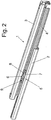
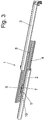
- FIGS. 1 to 3 is denoted by the reference numeral 1, a fully illustrated telescopic guide rail comprising a body side fixable carcass rail 2, a connectable to a pull-out part such as a drawer running rail 3 and arranged between the carcass rail 2 and the running rail 3, aussverinrnde center rail 4.
- the telescopic guide rail 1 is provided with a flow control 5, by means of which it is ensured that the running rail 3 can only be moved relative to the center rail 4, when the middle rail 4 is extended to its adjacent body rail 2 maximum, also can on the flow control. 5 be ensured that the center rail 4 from its fully extended position can only be moved back into the closed position when the running rail 3 has been moved back relative to the center rail 4 again maximally in the insertion direction.
- Such a sequence control 5 is desirable in order to avoid an uncontrolled displacement of the center rail 4 relative to the carcass rail 2 and / or the running rail 3, resulting in a favorable load on the rail components. Moreover, the controlled process has a very favorable influence on the operating force and the lowering.
- the sequence control 5 comprises a coupling member 6 and a first sliding block 7 fastened to the carcass rail 2 and a second sliding block 8 fastened to the running rail 3.
- sliding block is here purely functionally to be considered, since it is the sliding blocks 7 and 8 are components in the form of pins, which are attached on the one hand to the carcass rail 2 and on the other hand to the running rail 3.
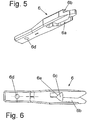
- the coupling member 6 is, which in particular the FIGS. 5 and 6 make clear, provided with a first slide guide 6a and a second slide guide 6b, wherein the two sliding guides 6a and 6b are arranged in mirror image to each other and extend substantially V-shaped spread apart.
- the two slotted guides 6a and 6b are arranged within the coupling member 6 in different planes.
- the depth of the slide guides 6a and 6b is slightly larger than the total thickness of the coupling member 6, so that there is an opening 6c in the overlap region of the two slide guides 6a and 6b.
- the coupling member 6 At its end facing away from the slide guides 6a and 6b, the coupling member 6 is equipped with a bearing bore 6d.
- This bearing bore 6d will pass through a bearing pin 9, which is connected to a fixedly mounted on the center rail 4 bearing block 10.
- the axis of the bearing pin 9 extends perpendicular to the displacement plane of the entire telescopic guide rail 1.
- the coupling member 6 is mounted pivotally within limits.
- the attached to the carcass rail 2 first sliding block 7 is assigned to the corresponding downwardly facing first slide guide 6a.
- the coupling member 6 is then pivoted about the axis of the bearing pin 7, whereby a release of the blockage between the located on the running rail 3 sliding block 8 and the coupling member 6 and simultaneously causes a block between the attached to the carcass rail 2 sliding block 7 and the coupling member 6 becomes.
- the running rail 3 can be separated from the center rail 4 and pulled completely opposite to this, while at the same time the middle rail 4 is secured or blocked against pushing back relative to the carcass rail 2.
- the coupling member 6 is a total of one piece made of plastic. Due to the opening 6c in the transition region between the two slotted guides 6a and 6b here is a certain spring elasticity achieved by the noise during the "switching" between the individual coupling states described above, can be largely damped. In addition, in the storage area of the coupling member 6, a damping spring (not shown) is provided be, which can also take care of the noise attenuation when switching the coupling member 6 care.
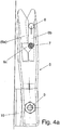
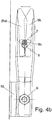
- FIGS. 4a to 4d show again in a schematic representation of the sequence of switching of the coupling member 6 through the two sliding blocks 7 and 8.
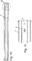
- FIGS. 10 to 12 show, the center rail 4, on which the coupling member 6 is pivotally mounted, with two mutually angled forms 11, which is associated with a corresponding recess 12 of the coupling member 6.
- the forms 11 and the recess 12 are arranged so that the coupling member 6 is secured in both possible end positions during pivoting against unintentional leaving this pivot position, that is, the coupling member 6 can not fall out of gravity by gravity from one of the pivoting positions. This opens up the possibility of using a telescopic guide rail according to FIGS. 7 to 11 without any modification both on the left and on the right side of a furniture pull-out.
- the characteristics 11 may also be provided on the coupling member 6 and accordingly the corresponding recesses may be provided on the center rail 4.
- the corresponding recesses may be provided on the center rail 4.
- Magnetic regions can also be provided for this purpose on the named components.
- the coupling member 6 which in turn is made entirely of a plastic, in the region of its bearing bore 6d provided with an opening 13 within which spring-like webs 14 are arranged, which carry the central region 15 with the bearing bore 6d.
- this central portion 15 of the coupling member 6 having the bearing bore 6d can be sprung to a certain extent in the direction of displacement and thus damped.
- the coupling member 6 is mounted on the side of the middle rail 4 facing the running rail 3.
- the attached to the carcass rail 2 sliding block 7 can interact properly with the coupling member 6, in the region of the center rail 4 is an opening 16 is provided through which engages the at least the sliding block 7 associated with the corresponding region of the control cam of the coupling member 6.
- sliding plane of the telescopic guide rail 1 has been used repeatedly. This is understood to mean a horizontal plane in the use position within which a furniture drawer mounted on two telescopic guide rails according to the invention is moved.
Description
Die vorliegende Erfindung betrifft eine Teleskopfiihrungsschiene für Möbelauszüge wie Schubkästen oder dergleichen, umfassend eine an einem Möbelkorpus festlegbare Korpusschiene, eine mit einem Möbelauszug verbindbare Laufschiene und eine zwischen der Korpusschiene und der Laufschiene angeordnete, auszugsverlängernde Mittelschiene und eine Ablaufsteuerung, mittels derer die Laufschiene beim Ausfahren aus der Schließlage heraus solange mit der Mittelschiene gekoppelt ist, bis die Mittelschiene ihre maximale Auszugsposition erreicht hat und in dieser Position unter gleichzeitiger Entkopplung der Laufschiene von der Mittelschiene gegenüber der Korpusschiene blockiert ist und die Mittelschiene erst dann wieder gegenüber der Korpusschiene in Schließrichtung verschiebbar ist, wenn die Laufschiene gegenüber der zunächst blockierten Mittelschiene maximal in Einschubrichtung verschoben und dabei wieder mit der Mittelschiene gekoppelt ist.The present invention relates to a Teleskopfiihrungsschiene for furniture drawer extensions such as drawers or the like, comprising a fixable on a furniture carcass rail, connectable to a furniture drawer track and arranged between the carcass rail and the runner, aussverlängernde middle rail and a flow control, by means of which the running rail during extension the closed position as long as coupled to the middle rail until the middle rail has reached its maximum extension position and is blocked in this position with simultaneous decoupling of the running rail of the center rail relative to the carcass rail and the center rail only again against the carcass rail in the closing direction is displaced when the running rail is displaced maximally in the direction of insertion in relation to the initially blocked center rail and in the process is again coupled to the middle rail.
Teleskopführungsschienen der gattungsgemäßen Art sind in vielerlei Ausführungsformen bekannt. So sind z.B. sogenannte "Quadro-Auszüge" bekannt, bei denen im Bereich der Laufbahnen Wälzkörper in Form von Kugeln vorgesehen sind. Derartige Teleskopführungsschienen sind besonders tragfähig. Bei derartigen Teleskopführungsschienen liegen die Korpusschiene, die auszugsverlängernde Mittelschiene sowie die mit einem Möbelauszug verbindbare Laufschiene in Gebrauchsstellung vertikal übereinander.Telescopic guide rails of the generic type are known in many embodiments. Thus, e.g. so-called "Quadro-extracts" known, in which rolling bodies are provided in the form of balls in the raceways. Such telescopic guide rails are particularly sustainable. In such telescopic guide rails are the carcass rail, the aussverlängernde center rail and connectable to a furniture drawer running rail in the use position vertically above the other.
Es gibt auch Teleskopführungsschienen der gattungsgemäßen Art, bei denen die im Wesentlichen C-förmigen Profile der Korpusschiene, der auszugsverlängernden Mittelschiene sowie der Laufschiene in Gebrauchsstellung horizontal nebeneinander liegend angeordnet sind.There are also telescopic guide rails of the generic type, in which the substantially C-shaped profiles of the carcass rail, the aussverlängernden middle rail and the running rail are arranged horizontally next to each other in the use position.
Bezüglich der Ablaufsteuerung sind ebenfalls unterschiedliche Ausführungsformen bekannt, wobei die Ablaufsteuerungen im Bereich der Laufbahnen der Teleskopführungsschienen angeordnet sind. Dadurch kann die Tragfähigkeit der Teleskopführungsschienen negativ beeinträchtigt werden, insbesondere dann, wenn durch die Anordnung einer Ablaufsteuerung ein Teil der Laufbahnen nicht mit Kugeln zur Erhöhung der Tragfähigkeit ausgestattet sein kann.With regard to the sequence control, different embodiments are also known, wherein the sequence controls are arranged in the region of the raceways of the telescopic guide rails. As a result, the carrying capacity of the telescopic guide rails can be adversely affected, especially if by the arrangement of a flow control part of the raceways can not be equipped with balls to increase the carrying capacity.
Teleskopführungsschienen mit einer Ablaufsteuerung die nicht im Bereich der Laufbahnen der Kugeln angeordnet sind, sind auch bekannt. Solche Teleskopführungsschienen werden in den Patentdokumenten
Der vorliegenden Erfindung liegt die Aufgabe zugrunde, eine Teleskopführungsschiene der gattungsgemäßen Art zu schaffen, die sich durch einen besonders einfachen und die Tragfähigkeit der Teleskopführungsschiene in keiner Weise beeinträchtigende Ablaufsteuerung auszeichnet.The present invention has for its object to provide a telescopic guide rail of the generic type, which is characterized by a particularly simple and the carrying capacity of the telescopic guide rail in any way impairing flow control.
Eine Lösung dieser Aufgabe besteht erfindungsgemäß darin, dass die Ablaufsteuerung aus einem mit zwei spiegelbildlich zueinander verlaufenden Kulissenführungen versehenen Koppelglied und aus einem an der Korpusschiene befestigten und mit einer ersten der Kulissenführungen zugeordneten ersten Kulissenstein und einem zweiten, an der Laufschiene befestigten und der zweiten Kulissenführung zugeordneten Kulissenstein besteht, wobei das Koppelglied um eine lotrecht zur Verschiebeebene der Teleskopführungsschiene verlaufende Achse verschwenkbar gelagert ist und die Kulissenführungen V-förmig gegeneinander gespreizt verlaufen derart, dass beim Einlaufen des ersten Kulissensteines in die ihm zugeordnete erste Kulissenführung ein Umschalten des Koppelgliedes und eine damit verbundene Freigabe des zweiten Kulissensteines aus der ihm zugeordneten zweiten Kulissenführung bewirkt und umgekehrt.A solution to this problem according to the invention is that the sequence control from a provided with two mirror images mutually sliding links provided coupling member and attached to the carcass rail and associated with a first of the link guides first sliding block and a second, attached to the running rail and the second link guide assigned Sliding block consists, wherein the coupling member is pivotally mounted about a perpendicular to the sliding plane of the telescopic guide rail extending axis and the slotted guides V-shaped spread apart such that when entering the first sliding block in the first link guide assigned to him a switching of the coupling member and an associated release causes the second sliding block from the associated second link guide and vice versa.
Diese angegebene Lösung ist bestimmt für eine Teleskopführungsschiene, bei der die Korpusschiene, die Mittelschiene und die Laufschiene in Gebrauchsstellung vertikal übereinander angeordnet sind. Die erfindungsgemäße Ablaufsteuerung kann dabei mit großem Vorteil außerhalb des Laufbahnenbereiches der einzelnen Schienenelemente angeordnet sein und beeinträchtigt somit in keiner Weise die Tragfähigkeit der gesamten Teleskopführungsschiene, insbesondere auch dann nicht, wenn diese mit Wälzkörpern in Form von Kugeln im Bereich der Laufbahnen ausgestattet ist. Darüber hinaus zeichnet sich die erfindungsgemäße Teleskopführungsschiene dadurch aus, dass die Ablaufsteuerung einen extrem einfachen und unkomplizierten Aufbau aufweist und letztlich nur aus dem Koppelglied mit den Kulissenführungen und den an der Korpusschiene einerseits und der Laufschiene andererseits angeschlossenen Kulissensteinen besteht.This specified solution is intended for a telescopic guide rail, in which the carcass rail, the center rail and the running rail in the position of use are arranged vertically one above the other. The sequence control according to the invention can be arranged with great advantage outside of the raceway region of the individual rail elements and thus does not affect in any way the carrying capacity of the entire telescopic guide rail, especially not even if it is equipped with rolling elements in the form of balls in the raceways. In addition, the telescopic guide rail according to the invention is characterized in that the flow control has an extremely simple and uncomplicated structure and ultimately only from the coupling member with the slotted guides and on the body rail on the one hand and the running rail on the other hand connected sliding blocks exists.
Eine weitere Lösung der erfindungsgemäßen Aufgabe besteht darin, dass die Ablaufsteuerung aus einem mit zwei spiegelbildlich zueinander verlaufenden Kulissenführungen versehenen Koppelglied und aus einem an der Korpusschiene befestigten und mit einer ersten der Kulissenführungen zugeordneten ersten Kulissenstein und einem zweiten, an der Laufschiene befestigten und der zweiten Kulissenführung zugeordneten Kulissenstein besteht, wobei das Koppelglied um eine parallel zur Verschiebeebene der Teleskopführungsschiene verlaufende Achse verschwenkbar gelagert ist und die Kulissenführungen V-förmig gegeneinander gespreizt verlaufen derart, dass beim Einlaufen des ersten Kulissensteines in die ihm zugeordnete erste Kulissenführung ein Umschalten des Koppelgliedes und eine damit verbundene Freigabe des zweiten Kulissensteines aus der ihm zugeordneten zweiten Kulissenführung bewirkt und umgekehrt.A further solution of the object according to the invention consists in that the sequence control consists of a coupling member provided with two mirror-symmetrical slide links and a first sliding block attached to the carcass rail and a first of the sliding guides and a second sliding guide fastened to the running rail and the second sliding guide associated sliding block consists, wherein the coupling member is pivotally mounted about an axis parallel to the sliding plane of the telescopic guide rail axis and the slide guides V-shaped spread apart extend such that when entering the first sliding block in the associated first link guide switching the coupling member and an associated Release of the second sliding block from the associated second link guide causes and vice versa.
Diese Lösung ist bestimmt für eine Teleskopführungsschiene, bei der die Korpusschiene, die Mittelschiene und die Laufschiene in Gebrauchsstellung horizontal nebeneinander liegend angeordnet sind.This solution is intended for a telescopic guide rail, in which the carcass rail, the center rail and the running rail in the position of use are arranged horizontally next to each other.
Auch für diese Lösung gelten die vorstehend genannten Vorteile.Also for this solution apply the advantages mentioned above.
Auch der Funktionsablauf der Ablaufsteuerungen ist in beiden Fällen äußerst unkompliziert und einfach, da das Umschalten des Koppelgliedes durch den jeweils in das Koppelglied bzw. in eine der dort vorgesehenen Führungsnuten einlaufenden Kulissenstein erfolgt, so dass beim eigentlichen Schaltvorgang ein Kulissenstein in eine Kopplungsstellung gebracht und der bis dahin in Kopplungsstellung befindliche weitere Kulissenstein aus der Kopplungsposition herausbewegt werden kann. Somit gibt es auch im Übergangsbereich keine unkontrollierte und ungewollte Verschiebemöglichkeit für das jeweils zu blockierende Schienenelement, d.h., dass die Mittelschiene zeitgleich mit der Entkopplung von der Laufschiene mit der Korpusschiene gekoppelt und gegenüber dieser blockiert wird und umgekehrt auch wiederum zeitgleich mit der Laufschiene gekoppelt wird, wenn die Blockierung gegenüber der Korpusschiene aufgehoben ist.The operation sequence of the sequential control is extremely uncomplicated and simple in both cases, since the switching of the coupling member by the incoming respectively in the coupling member or in one of the guide grooves provided there sliding block, so that the actual switching a sliding block brought into a coupling position and the until then located in the coupling position further sliding block can be moved out of the coupling position. Thus, there is no uncontrolled and unintentional displacement possibility for each rail element to be blocked in the transition region, ie, that the middle rail is coupled at the same time with the decoupling of the running rail with the carcass rail and blocked with respect to this and vice versa is also coupled at the same time with the running rail, if the blockage over the carcass rail is canceled.
Für diese Schaltvorgänge sind, wie schon erwähnt, lediglich die einfachen Bauteile erforderlich, so dass ein dauerhaft störungsfreier Betrieb einer derartigen Teleskopführungsschiene gewährleistet ist.For these switching operations, as already mentioned, only the simple components are required so that a permanently trouble-free operation of such a telescopic guide rail is ensured.
Weitere Merkmale der Erfindung sind Gegenstand von Unteransprüchen.Further features of the invention are the subject of dependent claims.
In den beigefügten Zeichnungen sind Ausführungsbeispiele der Erfindung dargestellt, welche im Folgenden näher beschrieben werden.In the accompanying drawings embodiments of the invention are shown, which are described in more detail below.
Es zeigen:
Figur 1- eine perspektivische Darstellung einer erfindungsgemäßen Teleskopführungsschiene im vollkommen zusammengeschobenen Zustand
Figur 2- eine Perspektivdarstellung der Teleskopführung gemäß
Figur 1 Figur 3- eine Perspektivdarstellung der erfindungsgemäßen Teleskopführungsschiene im ausgezogenen Zustand
- Figuren 4a bis 4d
- Draufsichten auf ein Koppelglied einer Ablaufsteuerung der Führungsschiene in verschiedenen Verschiebepositionen
Figur 5- eine Perspektivdarstellung des Koppelgliedes der Ablaufsteuerung
Figur 6- eine Draufsicht auf das Koppelglied gemäß
Figur 5 Figur 7- eine Perspektivdarstellung einer Teleskopführungsschiene mit aufgebrochen gezeigter Laufschiene nach einem weiteren Ausführungsbeispiel der Erfindung
Figur 8- eine Ansicht der Teleskopführungsschiene in Richtung des Pfeiles VIII in
Figur 7 Figur 9- die in
Figur 8 Figur 10- eine der
Figur 8 Figur 11- die in
Figur 10 Figur 12- eine Ansicht eines Koppelgliedes der Teleskopführungsschiene nach den
Figuren 7 bis 9
- FIG. 1
- a perspective view of a telescopic guide rail according to the invention in the fully collapsed state
- FIG. 2
- a perspective view of the telescopic guide according to
FIG. 1 in a shift intermediate position - FIG. 3
- a perspective view of the telescopic guide rail according to the invention in the extended state
- FIGS. 4a to 4d
- Top views of a coupling member of a flow control of the guide rail in different displacement positions
- FIG. 5
- a perspective view of the coupling member of the flow control
- FIG. 6
- a plan view of the coupling member according to
FIG. 5 - FIG. 7
- a perspective view of a telescopic guide rail with broken shown running rail according to another embodiment of the invention
- FIG. 8
- a view of the telescopic guide rail in the direction of arrow VIII in
FIG. 7 at full extension - FIG. 9
- in the
FIG. 8 with IX designated detail in an enlarged view - FIG. 10
- one of the
FIG. 8 corresponding view of an aussverlängernden middle rail of the telescopic guide - FIG. 11
- in the
FIG. 10 with XI designated detail in an enlarged view - FIG. 12
- a view of a coupling member of the telescopic guide rail after the
FIGS. 7 to 9 ,
In den
Außerdem ist die Teleskopführungsschiene 1 mit einer Ablaufsteuerung 5 versehen, mittels derer sichergestellt wird, dass die Laufschiene 3 erst dann gegenüber der Mittelschiene 4 verschoben werden kann, wenn die Mittelschiene 4 gegenüber der ihr benachbarten Korpusschiene 2 maximal ausgezogen ist, außerdem kann über die Ablaufsteuerung 5 sichergestellt werden, dass die Mittelschiene 4 aus ihrer vollständig ausgezogenen Position erst dann wieder in Schließstellung zurückbewegt werden kann, wenn die Laufschiene 3 gegenüber der Mittelschiene 4 wieder maximal in Einschubrichtung zurückbewegt worden ist.In addition, the
Eine derartige Ablaufsteuerung 5 ist wünschenswert, um ein unkontrolliertes Verschieben der Mittelschiene 4 gegenüber der Korpusschiene 2 und/oder der Laufschiene 3 zu vermeiden, woraus sich eine günstige Belastung der Schienenkomponenten ergibt. Überdies hat der gesteuerte Ablauf einen äußerst günstigen Einfluss auf die Betätigungskraft sowie die Absenkung.Such a
Die Ablaufsteuerung 5 umfasst ein Koppelglied 6 und einen an der Korpusschiene 2 befestigten ersten Kulissenstein 7 sowie einen an der Laufschiene 3 befestigten zweiten Kulissenstein 8.The
Der Begriff "Kulissenstein" ist hier rein funktionsbedingt zu betrachten, da es sich bei den Kulissensteinen 7 und 8 um Bauteile in Form von Stiften handelt, die einerseits an der Korpusschiene 2 und andererseits an der Laufschiene 3 befestigt sind.The term "sliding block" is here purely functionally to be considered, since it is the sliding
Das Koppelglied 6 ist, was insbesondere die
An seinem den Kulissenführungen 6a und 6b abgewandt liegenden Ende ist das Koppelglied 6 mit einer Lagerbohrung 6d ausgestattet. Diese Lagerbohrung 6d wird durchtreten von einem Lagerzapfen 9, der an einem ortsfest an der Mittelschiene 4 befestigten Lagerbock 10 angeschlossen ist. Die Achse des Lagerzapfens 9 verläuft lotrecht zur Verschiebeebene der gesamten Teleskopführungsschiene 1. Um diese Achse ist das Koppelglied 6 in Grenzen schwenkbar gelagert.At its end facing away from the slide guides 6a and 6b, the
Der an der Korpusschiene 2 befestigte erste Kulissenstein 7 ist der entsprechend nach unten weisenden, ersten Kulissenführung 6a zugeordnet.The attached to the
Der an der Laufschiene 3 befestigte zweite Kulissenstein 8 hingegen ist der nach oben weisenden, zweiten Kulissenführung 6b zugeordnet.The attached to the running
In der aus
Erst dann, wenn die Laufschiene 3 wieder in Einschubrichtung zurückgefahren wird und der an der Laufschiene 3 befestigte Kulissenstein 8 in die ihm zugeordnete, obere oder zweite Kulissenführung 6b einläuft, wird das Koppelglied 6 wieder um seine Achse 7 geschwenkt, wodurch einerseits nunmehr wieder eine Kopplung zwischen Mittelschiene 4 und Laufschiene 3 und eine Entkopplung zwischen Mittelschiene 4 und Korpusschiene 2 herbeigeführt wird. Somit kann die gekoppelte Einheit von Mittelschiene 4 und Laufschiene 3 wieder zurück in ihre Schließlage bewegt werden.Only then, when the running
Das Koppelglied 6 ist insgesamt einstückig aus Kunststoff hergestellt. Bedingt durch den Durchbruch 6c im Übergangsbereich zwischen den beiden Kulissenführungen 6a und 6b wird hier eine gewisse Federelastizität erreicht, durch die Geräusche beim "Umschalten" zwischen den einzelnen, vorstehend beschriebenen Kopplungszuständen, weitestgehend gedämpft werden können. Zusätzlich kann im Lagerbereich des Koppelgliedes 6 eine Dämpfungsfeder (nicht dargestellt) vorgesehen sein, die ebenfalls zur Geräuschdämpfung beim Umschalten des Koppelgliedes 6 Sorge tragen kann.The
Die
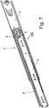
Im Gegensatz zu dem vorstehend beschriebenen Ausführungsbeispiel, bei dem die Korpusschiene, die Mittelschiene und die Laufschiene in Gebrauchsstellung vertikal übereinander liegend angeordnet sind, ist in den Zeichnungen 7 bis 12 ein Ausführungsbeispiel der Erfindung dargestellt, bei dem die besagten Schienenteile 2, 4, 3 in Gebrauchsstellung horizontal nebeneinander angeordnet sind.In contrast to the embodiment described above, in which the carcass rail, the center rail and the rail are arranged vertically one above the other in the use position, an embodiment of the invention is shown in the
Hieraus ergibt sich dann der weitere Unterschied zum Ausführungsbeispiel nach den
Um diesen Lagerzapfen 9 kann nun wieder das Koppelglied 6 in Grenzen verschwenkt und durch die wechselweise an der Korpusschiene 2 bzw. der Laufschiene 3 befestigten Kulissensteine so gesteuert werden, wie dies beim Beschreiben des Ausführungsbeispieles nach den
Wie die
Die Ausprägungen 11 und die Aussparung 12 sind so angeordnet, dass das Koppelglied 6 in beiden möglichen Endstellungen beim Verschwenken gegen unbeabsichtigtes Verlassen dieser Verschwenkposition gesichert ist, d.h., das Koppelglied 6 kann nicht durch Schwerkraft aus einer der Verschwenkpositionen herausfallen. Damit wird die Möglichkeit eröffnet, eine Teleskopführungsschiene gemäß den Figuren 7 bis 11 ohne jedwede Änderung sowohl links- wie auch rechtsseitig eines Möbelauszuges zu verwenden.The
Alternativ können selbstverständlich die Ausprägungen 11 auch am Koppelglied 6 vorgesehen sein und dementsprechend die korrespondierenden Aussparungen an der Mittelschiene 4 vorgesehen sein. Darüber hinaus ist es auch denkbar, statt linienförmiger, durchgehender Ausprägungen 11 und entsprechend linienförmig durchgängiger Aussparungen 12 zum Beispiel jeweils buckelartige Erhebungen an einem der korrespondierenden Bauteile und entsprechende Durchbrechungen oder Löcher im jeweils anderen Bauteil vorzusehen, um die Lage des Koppelgliedes 6 in seinen möglichen Endstellungen fixieren zu können. Auch magnetische Bereiche können zu diesem Zweck an den genannten Bauteilen vorgesehen sein.Alternatively, of course, the
Wie insbesondere auch
Beim Ausführungsbeispiel gemäß den
Alternativ wäre auch die Lagerung des Koppelgliedes 6 zwischen der Korpusschiene 2 und der Mittelschiene 4 denkbar, wobei dann selbstverständlich ein Durchgreifen des Durchbruches 16 durch den entsprechenden Bereich des Koppelgliedes 6 in Richtung der Laufschiene 3 erfolgen muss.Alternatively, the storage of the
Ebenso ist es vorstellbar, das Koppelglied 6 in seinem Lagerbereich aufzuspalten und die Lagerung auf beiden Seiten der Mittelschiene 4 vorzusehen.Likewise, it is conceivable to split the
Da sich die Funktion der Ablaufsteuerung 5 beim Ausführungsbeispiel nach den
In der Beschreibung der dargestellten Ausführungsbeispiele ist wiederholt der Begriff der "Verschiebeebene der Teleskopführungsschiene 1" verwendet worden. Hierunter ist eine in Gebrauchslage horizontale Ebene zu verstehen, innerhalb derer ein auf zwei erfindungsgemäßen Teleskopführungsschienen gelagerter Möbelauszug verschoben wird.In the description of the illustrated embodiments, the term "sliding plane of the
Claims (10)
- A telescopic guide rail (1) for telescopic furniture parts such as drawers or the like, comprising a body rail (2) which can be fixed to a furniture body, a running rail (3) which can be connected to the telescopic furniture part, a middle rail (4) which is arranged between the body rail (2) and the running rail (3) and increases the pull-out length, and a sequence control unit (5), by means of which the running rail (3) is coupled to the middle rail (4) during pull-out from the closing position for such a time until the middle rail (4) has reached its maximum pull-out position, and is blocked in said position in relation to the body rail (2) while the running rail (3) is simultaneously decoupled from the middle rail (4), and the middle rail (4) is displaceable in relation to the body rail (2) in the closing direction only when the running rail (3) is maximally displaced in the direction of insertion in relation to the initially blocked middle rail (4) and is thus coupled again to the middle rail (4) in this process, characterized in that the sequence control unit (5) consists of a coupling member (6), which is provided with two sliding guides (6a, 6b) extending in a mirror-inverted manner in relation to one another, and of a first sliding block (7) fixed to the body rail (2) and associated with a first one of the sliding guides (6a), and of a second sliding block (8) fixed to the running rail (3) and associated with the second sliding guide (6b), wherein the coupling member (6) is pivotably mounted about an axis (9) that extends perpendicularly to the plane of displacement of the telescopic guide rail (1), said plane of displacement being disposed horizontally in the in-use position, and the sliding guides (6a, 6b) extend in a V-shape by expanding one in relation to the other in such a way that during the entry of the first sliding block (7) into the first sliding guide (6a) associated therewith a switching of the coupling member (6) and thus a resulting release of the second sliding block (8) from the second sliding guide (6b) associated therewith is produced and vice versa.
- A telescopic guide rail according to claim 1, characterized in that the sliding blocks (7, 8) are arranged one on top of the other on the body rail (2) or running rail (3), and the sliding guides (6a, 6b) are accordingly arranged on the coupling member (6) in different height levels of the coupling member (6).
- A telescopic guide rail according to claim 2, characterized in that the depth of the first sliding guide (6a) which is downwardly open in the direction of the body rail (2) and the depth of the second sliding guide (6b) which is upwardly open in the direction of the running rail (3) are respectively greater than half the total thickness of the coupling member (6), so that in the overlapping region of the two sliding guides (6a, 6b) a breakthrough (6c) is formed in the region of the tip of their V-shaped progression.
- A telescopic guide rail according to one of the preceding claims, characterized in that the coupling member (6) is entirely integrally formed from a plastic material.
- A telescopic guide rail according to one of the preceding claims, characterized in that the coupling member (6) is pivotably mounted about the axis of a bearing pin (19), wherein the bearing pin (9) is supported by a bearing block (10) fastened to the middle rail (4).
- A telescopic guide rail according to claim 5, characterized in that damping means are provided in the region of the bearing of the coupling member (6) for damping the noise during switching of the coupling member (6).
- A telescopic guide rail according to claim 6, characterized in that one or several springs are provided as damping means.
- A telescopic guide rail (1) for telescopic furniture parts such as drawers or the like, comprising a body rail (2) which can be fixed to a furniture body, a running rail (3) which can be connected to the telescopic furniture part, a middle rail (4) which is arranged between the body rail (2) and the running rail (3) and increases the pull-out length, and a sequence control unit (5), by means of which the running rail (3) is coupled to the middle rail (4) during pull-out from the closing position for such a time until the middle rail (4) has reached its maximum pull-out position, and is blocked in said position in relation to the body rail (2) while the running rail (3) is simultaneously decoupled from the middle rail (4), and the middle rail (4) is displaceable in relation to the body rail (2) in the closing direction only when the running rail (3) is maximally displaced in the direction of insertion in relation to the initially blocked middle rail (4) and is thus coupled again to the middle rail (4) in this process, characterized in that the sequence control unit (5) consists of a coupling member (6), which is provided with two sliding guides (6a, 6b) extending in a mirror-inverted manner in relation to one another, and of a first sliding block (7) fixed to the body rail (2) and associated with a first one of the sliding guides (6a), and a second sliding block (8) fixed to the running rail (3) and associated with the second sliding guide (6b), wherein the coupling member (6) is pivotably mounted about an axis (9) that extends parallel to the plane of displacement of the telescopic guide rail (1), said plane of displacement being disposed horizontally in the in-use position, and the sliding guides (6a, 6b) extend in a V-shape by expanding one in relation to the other in such a way that during the entry of the first sliding block (7) into the first sliding guide (6a) associated therewith a switching of the coupling member (6) and thus a resulting release of the second sliding block (8) from the second sliding guide (6b) associated therewith is produced and vice versa.
- A telescopic guide rail according to one of the preceding claims, characterized in that the middle rail (4) is fitted with angularly extending punched-out portions (11) and the coupling member (6) is fitted with a recess (12) associated with said punched-out portions (11), wherein one each of the punched-out portions (11) engages in the recess (12) of the coupling member (6) when the coupling member (6) is pivoted to one of its possible switching positions.
- A telescopic guide rail according to one of the preceding claims, characterized in that the coupling member (6) is provided in the ambient region of its bearing hole (6d) with a breakthrough, within which spring-like webs (14) resiliently support a central region (15) having the bearing hole (6d).
Applications Claiming Priority (3)
| Application Number | Priority Date | Filing Date | Title |
|---|---|---|---|
| DE202007006692 | 2007-05-07 | ||
| DE202008004597U DE202008004597U1 (en) | 2007-05-07 | 2008-04-02 | Telescopic guide rail |
| PCT/EP2008/055157 WO2008135425A1 (en) | 2007-05-07 | 2008-04-28 | Telescopic guide rail |
Publications (2)
| Publication Number | Publication Date |
|---|---|
| EP2144530A1 EP2144530A1 (en) | 2010-01-20 |
| EP2144530B1 true EP2144530B1 (en) | 2017-06-21 |
Family
ID=39768321
Family Applications (1)
| Application Number | Title | Priority Date | Filing Date |
|---|---|---|---|
| EP08759387.7A Not-in-force EP2144530B1 (en) | 2007-05-07 | 2008-04-28 | Telescopic guide rail |
Country Status (5)
| Country | Link |
|---|---|
| EP (1) | EP2144530B1 (en) |
| CN (1) | CN101720192B (en) |
| DE (1) | DE202008004597U1 (en) |
| ES (1) | ES2640977T3 (en) |
| WO (1) | WO2008135425A1 (en) |
Cited By (1)
| Publication number | Priority date | Publication date | Assignee | Title |
|---|---|---|---|---|
| DE102017120181A1 (en) | 2017-09-01 | 2019-03-07 | Paul Hettich Gmbh & Co. Kg | pull-out guide |
Families Citing this family (9)
| Publication number | Priority date | Publication date | Assignee | Title |
|---|---|---|---|---|
| DE202010011853U1 (en) * | 2010-08-25 | 2011-11-28 | Grass Gmbh | Guide unit for guiding a movable relative to a furniture body furniture drawer, for example, a drawer |
| CN103126354B (en) * | 2013-03-23 | 2015-06-03 | 伍志勇 | Noise-reducing mechanism of wheel-typed drawer sliding rail |
| DE102013113672A1 (en) * | 2013-06-14 | 2014-12-18 | Paul Hettich Gmbh & Co. Kg | pull-out system |
| DE102017115952A1 (en) | 2017-07-14 | 2019-01-17 | Paul Hettich Gmbh & Co. Kg | Sliding and lifting mechanism for a furniture or household appliance and furniture or household appliance with such a sliding and lifting mechanism |
| CN108035121B (en) * | 2018-01-04 | 2024-01-05 | 南京贝奇工业设计有限公司 | Automatic drawer box for washing machine and control method thereof |
| US10768387B2 (en) * | 2018-04-06 | 2020-09-08 | Belden Canada Inc. | Cross connect system and tray |
| JP6962568B2 (en) * | 2018-05-29 | 2021-11-05 | 日本アキュライド株式会社 | Slide rail with telescopic order mechanism |
| DE102018118973A1 (en) * | 2018-08-03 | 2020-02-06 | Liebherr-Verzahntechnik Gmbh | telescopic rail |
| DE202018106058U1 (en) * | 2018-10-23 | 2020-01-24 | Accuride International Gmbh | telescopic rail |
Family Cites Families (3)
| Publication number | Priority date | Publication date | Assignee | Title |
|---|---|---|---|---|
| EP0620993A1 (en) * | 1993-04-23 | 1994-10-26 | Alfit Aktiengesellschaft | Drawer with double extensible guide |
| AT406330B (en) * | 1996-01-16 | 2000-04-25 | Blum Gmbh Julius | EXTENDING GUIDE FOR A DRAWER |
| CN2642137Y (en) * | 2003-04-30 | 2004-09-22 | 南俊国际股份有限公司 | Working life increasable and length extensible slideway structure for drawer |
-
2008
- 2008-04-02 DE DE202008004597U patent/DE202008004597U1/en not_active Expired - Lifetime
- 2008-04-28 EP EP08759387.7A patent/EP2144530B1/en not_active Not-in-force
- 2008-04-28 WO PCT/EP2008/055157 patent/WO2008135425A1/en active Application Filing
- 2008-04-28 CN CN200880015068XA patent/CN101720192B/en not_active Expired - Fee Related
- 2008-04-28 ES ES08759387.7T patent/ES2640977T3/en active Active
Non-Patent Citations (1)
| Title |
|---|
| None * |
Cited By (2)
| Publication number | Priority date | Publication date | Assignee | Title |
|---|---|---|---|---|
| DE102017120181A1 (en) | 2017-09-01 | 2019-03-07 | Paul Hettich Gmbh & Co. Kg | pull-out guide |
| WO2019042980A1 (en) | 2017-09-01 | 2019-03-07 | Paul Hettich Gmbh & Co. Kg | Pull-out guide |
Also Published As
| Publication number | Publication date |
|---|---|
| WO2008135425A1 (en) | 2008-11-13 |
| CN101720192B (en) | 2011-12-21 |
| EP2144530A1 (en) | 2010-01-20 |
| ES2640977T3 (en) | 2017-11-07 |
| DE202008004597U1 (en) | 2008-09-18 |
| CN101720192A (en) | 2010-06-02 |
Similar Documents
| Publication | Publication Date | Title |
|---|---|---|
| EP2144530B1 (en) | Telescopic guide rail | |
| AT509540B1 (en) | EXTRACTION GUIDE FOR DRAWERS | |
| EP1816927B1 (en) | Opening device for drawers | |
| EP2916688B1 (en) | Drawer pull out guide | |
| DE202005004336U1 (en) | Self-closing device for sliding doors, folding doors or similar furniture items has an energy storage component that is tensioned during door opening and then acts on the door to close it via an adapter and a cam on the door | |
| AT506062B1 (en) | ROLLS-pull-out | |
| DE112009000174T5 (en) | Slide guides for drawer systems and lock mechanisms | |
| DE202008016409U1 (en) | Self-closing device and pullout guide | |
| AT521133B1 (en) | Guide system for guiding a movably mounted door leaf | |
| WO2006106029A1 (en) | Telescopic guide for a furniture part that can be displaced in the body of a piece of furniture | |
| AT513856B1 (en) | Self-closing device for a movable furniture part | |
| DE10219448A1 (en) | drawer guide | |
| EP0957714B1 (en) | Flush-mounted extraction guide for drawers etc. | |
| EP3838069A1 (en) | Drawer slide guide | |
| EP3668350A1 (en) | Drawer pull-out guide | |
| AT517479B1 (en) | drawer | |
| EP2716182B1 (en) | Extension guide for a pull-out furniture part extendible from a furniture body | |
| EP1384420A1 (en) | Damped self closing mechanism | |
| AT520805A1 (en) | pull-out | |
| EP1103690A1 (en) | Fume venting device | |
| DE202005017635U1 (en) | Detachable coupling for linear power transmission, in particular for drawer rails | |
| EP4217562A1 (en) | Pull-out locking device for drawers | |
| EP1721547B1 (en) | Lateral guide for a pull-out element of a vertical drawer | |
| WO2008031472A1 (en) | Device for the displaceable arrangement of a sliding door | |
| EP4003095B1 (en) | Drawer pull-out guide |
Legal Events
| Date | Code | Title | Description |
|---|---|---|---|
| PUAI | Public reference made under article 153(3) epc to a published international application that has entered the european phase |
Free format text: ORIGINAL CODE: 0009012 |
|
| 17P | Request for examination filed |
Effective date: 20091023 |
|
| AK | Designated contracting states |
Kind code of ref document: A1 Designated state(s): AT BE BG CH CY CZ DE DK EE ES FI FR GB GR HR HU IE IS IT LI LT LU LV MC MT NL NO PL PT RO SE SI SK TR |
|
| AX | Request for extension of the european patent |
Extension state: AL BA MK RS |
|
| DAX | Request for extension of the european patent (deleted) | ||
| REG | Reference to a national code |
Ref country code: DE Ref legal event code: R079 Ref document number: 502008015411 Country of ref document: DE Free format text: PREVIOUS MAIN CLASS: A47B0088100000 Ipc: A47B0088493000 |
|
| GRAP | Despatch of communication of intention to grant a patent |
Free format text: ORIGINAL CODE: EPIDOSNIGR1 |
|
| RIC1 | Information provided on ipc code assigned before grant |
Ipc: A47B 88/493 20170101AFI20170120BHEP |
|
| INTG | Intention to grant announced |
Effective date: 20170210 |
|
| GRAS | Grant fee paid |
Free format text: ORIGINAL CODE: EPIDOSNIGR3 |
|
| GRAA | (expected) grant |
Free format text: ORIGINAL CODE: 0009210 |
|
| AK | Designated contracting states |
Kind code of ref document: B1 Designated state(s): AT BE BG CH CY CZ DE DK EE ES FI FR GB GR HR HU IE IS IT LI LT LU LV MC MT NL NO PL PT RO SE SI SK TR |
|
| REG | Reference to a national code |
Ref country code: GB Ref legal event code: FG4D Free format text: NOT ENGLISH |
|
| REG | Reference to a national code |
Ref country code: CH Ref legal event code: EP |
|
| REG | Reference to a national code |
Ref country code: IE Ref legal event code: FG4D Free format text: LANGUAGE OF EP DOCUMENT: GERMAN |
|
| REG | Reference to a national code |
Ref country code: AT Ref legal event code: REF Ref document number: 902156 Country of ref document: AT Kind code of ref document: T Effective date: 20170715 |
|
| REG | Reference to a national code |
Ref country code: DE Ref legal event code: R096 Ref document number: 502008015411 Country of ref document: DE |
|
| REG | Reference to a national code |
Ref country code: SE Ref legal event code: TRGR |
|
| REG | Reference to a national code |
Ref country code: NL Ref legal event code: MP Effective date: 20170621 |
|
| PG25 | Lapsed in a contracting state [announced via postgrant information from national office to epo] |
Ref country code: HR Free format text: LAPSE BECAUSE OF FAILURE TO SUBMIT A TRANSLATION OF THE DESCRIPTION OR TO PAY THE FEE WITHIN THE PRESCRIBED TIME-LIMIT Effective date: 20170621 Ref country code: FI Free format text: LAPSE BECAUSE OF FAILURE TO SUBMIT A TRANSLATION OF THE DESCRIPTION OR TO PAY THE FEE WITHIN THE PRESCRIBED TIME-LIMIT Effective date: 20170621 Ref country code: NO Free format text: LAPSE BECAUSE OF FAILURE TO SUBMIT A TRANSLATION OF THE DESCRIPTION OR TO PAY THE FEE WITHIN THE PRESCRIBED TIME-LIMIT Effective date: 20170921 Ref country code: GR Free format text: LAPSE BECAUSE OF FAILURE TO SUBMIT A TRANSLATION OF THE DESCRIPTION OR TO PAY THE FEE WITHIN THE PRESCRIBED TIME-LIMIT Effective date: 20170922 Ref country code: LT Free format text: LAPSE BECAUSE OF FAILURE TO SUBMIT A TRANSLATION OF THE DESCRIPTION OR TO PAY THE FEE WITHIN THE PRESCRIBED TIME-LIMIT Effective date: 20170621 |
|
| REG | Reference to a national code |
Ref country code: ES Ref legal event code: FG2A Ref document number: 2640977 Country of ref document: ES Kind code of ref document: T3 Effective date: 20171107 |
|
| REG | Reference to a national code |
Ref country code: LT Ref legal event code: MG4D |
|
| PG25 | Lapsed in a contracting state [announced via postgrant information from national office to epo] |
Ref country code: LV Free format text: LAPSE BECAUSE OF FAILURE TO SUBMIT A TRANSLATION OF THE DESCRIPTION OR TO PAY THE FEE WITHIN THE PRESCRIBED TIME-LIMIT Effective date: 20170621 Ref country code: NL Free format text: LAPSE BECAUSE OF FAILURE TO SUBMIT A TRANSLATION OF THE DESCRIPTION OR TO PAY THE FEE WITHIN THE PRESCRIBED TIME-LIMIT Effective date: 20170621 Ref country code: BG Free format text: LAPSE BECAUSE OF FAILURE TO SUBMIT A TRANSLATION OF THE DESCRIPTION OR TO PAY THE FEE WITHIN THE PRESCRIBED TIME-LIMIT Effective date: 20170921 |
|
| PG25 | Lapsed in a contracting state [announced via postgrant information from national office to epo] |
Ref country code: RO Free format text: LAPSE BECAUSE OF FAILURE TO SUBMIT A TRANSLATION OF THE DESCRIPTION OR TO PAY THE FEE WITHIN THE PRESCRIBED TIME-LIMIT Effective date: 20170621 Ref country code: CZ Free format text: LAPSE BECAUSE OF FAILURE TO SUBMIT A TRANSLATION OF THE DESCRIPTION OR TO PAY THE FEE WITHIN THE PRESCRIBED TIME-LIMIT Effective date: 20170621 Ref country code: EE Free format text: LAPSE BECAUSE OF FAILURE TO SUBMIT A TRANSLATION OF THE DESCRIPTION OR TO PAY THE FEE WITHIN THE PRESCRIBED TIME-LIMIT Effective date: 20170621 Ref country code: SK Free format text: LAPSE BECAUSE OF FAILURE TO SUBMIT A TRANSLATION OF THE DESCRIPTION OR TO PAY THE FEE WITHIN THE PRESCRIBED TIME-LIMIT Effective date: 20170621 |
|
| PG25 | Lapsed in a contracting state [announced via postgrant information from national office to epo] |
Ref country code: PL Free format text: LAPSE BECAUSE OF FAILURE TO SUBMIT A TRANSLATION OF THE DESCRIPTION OR TO PAY THE FEE WITHIN THE PRESCRIBED TIME-LIMIT Effective date: 20170621 Ref country code: IS Free format text: LAPSE BECAUSE OF FAILURE TO SUBMIT A TRANSLATION OF THE DESCRIPTION OR TO PAY THE FEE WITHIN THE PRESCRIBED TIME-LIMIT Effective date: 20171021 |
|
| REG | Reference to a national code |
Ref country code: DE Ref legal event code: R097 Ref document number: 502008015411 Country of ref document: DE |
|
| PLBE | No opposition filed within time limit |
Free format text: ORIGINAL CODE: 0009261 |
|
| STAA | Information on the status of an ep patent application or granted ep patent |
Free format text: STATUS: NO OPPOSITION FILED WITHIN TIME LIMIT |
|
| PG25 | Lapsed in a contracting state [announced via postgrant information from national office to epo] |
Ref country code: DK Free format text: LAPSE BECAUSE OF FAILURE TO SUBMIT A TRANSLATION OF THE DESCRIPTION OR TO PAY THE FEE WITHIN THE PRESCRIBED TIME-LIMIT Effective date: 20170621 |
|
| 26N | No opposition filed |
Effective date: 20180322 |
|
| PG25 | Lapsed in a contracting state [announced via postgrant information from national office to epo] |
Ref country code: SI Free format text: LAPSE BECAUSE OF FAILURE TO SUBMIT A TRANSLATION OF THE DESCRIPTION OR TO PAY THE FEE WITHIN THE PRESCRIBED TIME-LIMIT Effective date: 20170621 |
|
| PG25 | Lapsed in a contracting state [announced via postgrant information from national office to epo] |
Ref country code: MT Free format text: LAPSE BECAUSE OF FAILURE TO SUBMIT A TRANSLATION OF THE DESCRIPTION OR TO PAY THE FEE WITHIN THE PRESCRIBED TIME-LIMIT Effective date: 20170621 |
|
| PG25 | Lapsed in a contracting state [announced via postgrant information from national office to epo] |
Ref country code: MC Free format text: LAPSE BECAUSE OF FAILURE TO SUBMIT A TRANSLATION OF THE DESCRIPTION OR TO PAY THE FEE WITHIN THE PRESCRIBED TIME-LIMIT Effective date: 20170621 |
|
| REG | Reference to a national code |
Ref country code: CH Ref legal event code: PL |
|
| REG | Reference to a national code |
Ref country code: SE Ref legal event code: EUG |
|
| REG | Reference to a national code |
Ref country code: BE Ref legal event code: MM Effective date: 20180430 |
|
| GBPC | Gb: european patent ceased through non-payment of renewal fee |
Effective date: 20180428 |
|
| REG | Reference to a national code |
Ref country code: IE Ref legal event code: MM4A |
|
| PG25 | Lapsed in a contracting state [announced via postgrant information from national office to epo] |
Ref country code: LU Free format text: LAPSE BECAUSE OF NON-PAYMENT OF DUE FEES Effective date: 20180428 Ref country code: SE Free format text: LAPSE BECAUSE OF NON-PAYMENT OF DUE FEES Effective date: 20180429 |
|
| PG25 | Lapsed in a contracting state [announced via postgrant information from national office to epo] |
Ref country code: BE Free format text: LAPSE BECAUSE OF NON-PAYMENT OF DUE FEES Effective date: 20180430 Ref country code: GB Free format text: LAPSE BECAUSE OF NON-PAYMENT OF DUE FEES Effective date: 20180428 Ref country code: CH Free format text: LAPSE BECAUSE OF NON-PAYMENT OF DUE FEES Effective date: 20180430 Ref country code: LI Free format text: LAPSE BECAUSE OF NON-PAYMENT OF DUE FEES Effective date: 20180430 |
|
| PG25 | Lapsed in a contracting state [announced via postgrant information from national office to epo] |
Ref country code: FR Free format text: LAPSE BECAUSE OF NON-PAYMENT OF DUE FEES Effective date: 20180430 Ref country code: IE Free format text: LAPSE BECAUSE OF NON-PAYMENT OF DUE FEES Effective date: 20180428 Ref country code: IT Free format text: LAPSE BECAUSE OF NON-PAYMENT OF DUE FEES Effective date: 20180428 |
|
| REG | Reference to a national code |
Ref country code: AT Ref legal event code: MM01 Ref document number: 902156 Country of ref document: AT Kind code of ref document: T Effective date: 20180428 |
|
| REG | Reference to a national code |
Ref country code: ES Ref legal event code: FD2A Effective date: 20190912 |
|
| PG25 | Lapsed in a contracting state [announced via postgrant information from national office to epo] |
Ref country code: ES Free format text: LAPSE BECAUSE OF NON-PAYMENT OF DUE FEES Effective date: 20180429 Ref country code: AT Free format text: LAPSE BECAUSE OF NON-PAYMENT OF DUE FEES Effective date: 20180428 |
|
| PG25 | Lapsed in a contracting state [announced via postgrant information from national office to epo] |
Ref country code: TR Free format text: LAPSE BECAUSE OF FAILURE TO SUBMIT A TRANSLATION OF THE DESCRIPTION OR TO PAY THE FEE WITHIN THE PRESCRIBED TIME-LIMIT Effective date: 20170621 |
|
| PG25 | Lapsed in a contracting state [announced via postgrant information from national office to epo] |
Ref country code: PT Free format text: LAPSE BECAUSE OF FAILURE TO SUBMIT A TRANSLATION OF THE DESCRIPTION OR TO PAY THE FEE WITHIN THE PRESCRIBED TIME-LIMIT Effective date: 20170621 Ref country code: HU Free format text: LAPSE BECAUSE OF FAILURE TO SUBMIT A TRANSLATION OF THE DESCRIPTION OR TO PAY THE FEE WITHIN THE PRESCRIBED TIME-LIMIT; INVALID AB INITIO Effective date: 20080428 |
|
| PG25 | Lapsed in a contracting state [announced via postgrant information from national office to epo] |
Ref country code: CY Free format text: LAPSE BECAUSE OF FAILURE TO SUBMIT A TRANSLATION OF THE DESCRIPTION OR TO PAY THE FEE WITHIN THE PRESCRIBED TIME-LIMIT Effective date: 20170621 |
|
| PGFP | Annual fee paid to national office [announced via postgrant information from national office to epo] |
Ref country code: DE Payment date: 20210421 Year of fee payment: 14 |
|
| REG | Reference to a national code |
Ref country code: DE Ref legal event code: R119 Ref document number: 502008015411 Country of ref document: DE |
|
| PG25 | Lapsed in a contracting state [announced via postgrant information from national office to epo] |
Ref country code: DE Free format text: LAPSE BECAUSE OF NON-PAYMENT OF DUE FEES Effective date: 20221103 |