EP2144300A2 - Framework for a plate-shaped solar element - Google Patents
Framework for a plate-shaped solar element Download PDFInfo
- Publication number
- EP2144300A2 EP2144300A2 EP09162975A EP09162975A EP2144300A2 EP 2144300 A2 EP2144300 A2 EP 2144300A2 EP 09162975 A EP09162975 A EP 09162975A EP 09162975 A EP09162975 A EP 09162975A EP 2144300 A2 EP2144300 A2 EP 2144300A2
- Authority
- EP
- European Patent Office
- Prior art keywords
- frame member
- frame
- lower frame
- adhesive tape
- upper frame
- Prior art date
- Legal status (The legal status is an assumption and is not a legal conclusion. Google has not performed a legal analysis and makes no representation as to the accuracy of the status listed.)
- Granted
Links
- 239000000853 adhesive Substances 0.000 claims abstract description 13
- 238000004519 manufacturing process Methods 0.000 claims abstract description 8
- 230000001070 adhesive effect Effects 0.000 claims abstract description 7
- 239000002390 adhesive tape Substances 0.000 claims description 29
- 239000012790 adhesive layer Substances 0.000 claims description 16
- 238000000034 method Methods 0.000 description 5
- 239000000463 material Substances 0.000 description 3
- 239000011521 glass Substances 0.000 description 2
- 238000009434 installation Methods 0.000 description 2
- 239000002985 plastic film Substances 0.000 description 2
- 229920006255 plastic film Polymers 0.000 description 2
- XAGFODPZIPBFFR-UHFFFAOYSA-N aluminium Chemical compound [Al] XAGFODPZIPBFFR-UHFFFAOYSA-N 0.000 description 1
- 229910052782 aluminium Inorganic materials 0.000 description 1
- 239000013013 elastic material Substances 0.000 description 1
- 239000006260 foam Substances 0.000 description 1
- 238000009432 framing Methods 0.000 description 1
- 230000000149 penetrating effect Effects 0.000 description 1
- 239000004033 plastic Substances 0.000 description 1
- 238000003825 pressing Methods 0.000 description 1
- 238000007789 sealing Methods 0.000 description 1
- XLYOFNOQVPJJNP-UHFFFAOYSA-N water Substances O XLYOFNOQVPJJNP-UHFFFAOYSA-N 0.000 description 1
Images


Classifications
-
- H—ELECTRICITY
- H01—ELECTRIC ELEMENTS
- H01L—SEMICONDUCTOR DEVICES NOT COVERED BY CLASS H10
- H01L31/00—Semiconductor devices sensitive to infrared radiation, light, electromagnetic radiation of shorter wavelength or corpuscular radiation and specially adapted either for the conversion of the energy of such radiation into electrical energy or for the control of electrical energy by such radiation; Processes or apparatus specially adapted for the manufacture or treatment thereof or of parts thereof; Details thereof
- H01L31/04—Semiconductor devices sensitive to infrared radiation, light, electromagnetic radiation of shorter wavelength or corpuscular radiation and specially adapted either for the conversion of the energy of such radiation into electrical energy or for the control of electrical energy by such radiation; Processes or apparatus specially adapted for the manufacture or treatment thereof or of parts thereof; Details thereof adapted as photovoltaic [PV] conversion devices
- H01L31/042—PV modules or arrays of single PV cells
- H01L31/048—Encapsulation of modules
-
- F—MECHANICAL ENGINEERING; LIGHTING; HEATING; WEAPONS; BLASTING
- F24—HEATING; RANGES; VENTILATING
- F24S—SOLAR HEAT COLLECTORS; SOLAR HEAT SYSTEMS
- F24S25/00—Arrangement of stationary mountings or supports for solar heat collector modules
- F24S25/20—Peripheral frames for modules
-
- F—MECHANICAL ENGINEERING; LIGHTING; HEATING; WEAPONS; BLASTING
- F24—HEATING; RANGES; VENTILATING
- F24S—SOLAR HEAT COLLECTORS; SOLAR HEAT SYSTEMS
- F24S40/00—Safety or protection arrangements of solar heat collectors; Preventing malfunction of solar heat collectors
- F24S40/40—Preventing corrosion; Protecting against dirt or contamination
- F24S40/44—Draining rainwater or condensation
-
- F—MECHANICAL ENGINEERING; LIGHTING; HEATING; WEAPONS; BLASTING
- F24—HEATING; RANGES; VENTILATING
- F24S—SOLAR HEAT COLLECTORS; SOLAR HEAT SYSTEMS
- F24S80/00—Details, accessories or component parts of solar heat collectors not provided for in groups F24S10/00-F24S70/00
- F24S80/40—Casings
-
- F—MECHANICAL ENGINEERING; LIGHTING; HEATING; WEAPONS; BLASTING
- F24—HEATING; RANGES; VENTILATING
- F24S—SOLAR HEAT COLLECTORS; SOLAR HEAT SYSTEMS
- F24S80/00—Details, accessories or component parts of solar heat collectors not provided for in groups F24S10/00-F24S70/00
- F24S80/70—Sealing means
-
- H—ELECTRICITY
- H02—GENERATION; CONVERSION OR DISTRIBUTION OF ELECTRIC POWER
- H02S—GENERATION OF ELECTRIC POWER BY CONVERSION OF INFRARED RADIATION, VISIBLE LIGHT OR ULTRAVIOLET LIGHT, e.g. USING PHOTOVOLTAIC [PV] MODULES
- H02S30/00—Structural details of PV modules other than those related to light conversion
- H02S30/10—Frame structures
-
- F—MECHANICAL ENGINEERING; LIGHTING; HEATING; WEAPONS; BLASTING
- F24—HEATING; RANGES; VENTILATING
- F24S—SOLAR HEAT COLLECTORS; SOLAR HEAT SYSTEMS
- F24S25/00—Arrangement of stationary mountings or supports for solar heat collector modules
- F24S25/60—Fixation means, e.g. fasteners, specially adapted for supporting solar heat collector modules
- F24S2025/601—Fixation means, e.g. fasteners, specially adapted for supporting solar heat collector modules by bonding, e.g. by using adhesives
-
- Y—GENERAL TAGGING OF NEW TECHNOLOGICAL DEVELOPMENTS; GENERAL TAGGING OF CROSS-SECTIONAL TECHNOLOGIES SPANNING OVER SEVERAL SECTIONS OF THE IPC; TECHNICAL SUBJECTS COVERED BY FORMER USPC CROSS-REFERENCE ART COLLECTIONS [XRACs] AND DIGESTS
- Y02—TECHNOLOGIES OR APPLICATIONS FOR MITIGATION OR ADAPTATION AGAINST CLIMATE CHANGE
- Y02B—CLIMATE CHANGE MITIGATION TECHNOLOGIES RELATED TO BUILDINGS, e.g. HOUSING, HOUSE APPLIANCES OR RELATED END-USER APPLICATIONS
- Y02B10/00—Integration of renewable energy sources in buildings
- Y02B10/20—Solar thermal
-
- Y—GENERAL TAGGING OF NEW TECHNOLOGICAL DEVELOPMENTS; GENERAL TAGGING OF CROSS-SECTIONAL TECHNOLOGIES SPANNING OVER SEVERAL SECTIONS OF THE IPC; TECHNICAL SUBJECTS COVERED BY FORMER USPC CROSS-REFERENCE ART COLLECTIONS [XRACs] AND DIGESTS
- Y02—TECHNOLOGIES OR APPLICATIONS FOR MITIGATION OR ADAPTATION AGAINST CLIMATE CHANGE
- Y02E—REDUCTION OF GREENHOUSE GAS [GHG] EMISSIONS, RELATED TO ENERGY GENERATION, TRANSMISSION OR DISTRIBUTION
- Y02E10/00—Energy generation through renewable energy sources
- Y02E10/40—Solar thermal energy, e.g. solar towers
- Y02E10/47—Mountings or tracking
-
- Y—GENERAL TAGGING OF NEW TECHNOLOGICAL DEVELOPMENTS; GENERAL TAGGING OF CROSS-SECTIONAL TECHNOLOGIES SPANNING OVER SEVERAL SECTIONS OF THE IPC; TECHNICAL SUBJECTS COVERED BY FORMER USPC CROSS-REFERENCE ART COLLECTIONS [XRACs] AND DIGESTS
- Y02—TECHNOLOGIES OR APPLICATIONS FOR MITIGATION OR ADAPTATION AGAINST CLIMATE CHANGE
- Y02E—REDUCTION OF GREENHOUSE GAS [GHG] EMISSIONS, RELATED TO ENERGY GENERATION, TRANSMISSION OR DISTRIBUTION
- Y02E10/00—Energy generation through renewable energy sources
- Y02E10/50—Photovoltaic [PV] energy
-
- Y—GENERAL TAGGING OF NEW TECHNOLOGICAL DEVELOPMENTS; GENERAL TAGGING OF CROSS-SECTIONAL TECHNOLOGIES SPANNING OVER SEVERAL SECTIONS OF THE IPC; TECHNICAL SUBJECTS COVERED BY FORMER USPC CROSS-REFERENCE ART COLLECTIONS [XRACs] AND DIGESTS
- Y10—TECHNICAL SUBJECTS COVERED BY FORMER USPC
- Y10T—TECHNICAL SUBJECTS COVERED BY FORMER US CLASSIFICATION
- Y10T29/00—Metal working
- Y10T29/49—Method of mechanical manufacture
- Y10T29/4935—Heat exchanger or boiler making
- Y10T29/49355—Solar energy device making
Definitions
- the invention relates to a frame for a plate-shaped solar element and the use of such a frame for the production of a solar module.
- Solar modules consist of a frame, which comprises the solar element, which is usually a plurality of solar cells, which are arranged in a plane and embedded in a plastic film.
- the plastic film is usually covered by a glass plate and has a suddonkaschtechnik, which is usually also made of plastic.
- the solar element which is sometimes referred to as a frameless solar module or laminate is bordered by a frame which causes a stiffening of the solar element, the solar element, in particular the glass, protects during transport, and allows attachment of solar elements to building facilities.
- the framed solar element is usually referred to as a solar module.
- one-piece frames are usually used. Such a frame is pressed laterally on the outer edges of the solar element. Subsequently, the edges of the solar module are glued manually. This procedure is not very efficient.
- two-part frames which comprise a lower frame member on which the solar element is placed.
- the actual frame is obtained by pressing an upper frame member into the lower frame member to obtain a positive or positive connection, wherein a gap is formed between the lower and the upper frame member, is inserted into the edge portion of the solar element.
- DE 202 09 218 U1 discloses a two-part frame for a frameless solar module comprising a lower frame member having a surface on which the solar module is placed. Further, in the lower frame member, a slot is provided, in which a leg of an upper, angular frame member is inserted, whereby a positive and / or non-positive connection between the two frame elements is obtained.
- the edge region of the solar module is enveloped in an elastic material, for example a seal, which is arranged between the frame and solar module after assembly.
- an elastic material for example a seal
- the object of the invention is to eliminate the disadvantages of the prior art. It should in particular be given a frame for receiving a plate-shaped solar element, which allows a more efficient and cost-effective framing of solar elements.
- a frame for a plate-shaped solar element comprising a lower frame member having a first surface and preferably an upper frame member having a second surface, the second surface being opposite the first surface and being spaced therefrom to form a gap, which can receive the edge region of the plate-shaped solar element, wherein the first surface and the second surface are each equipped with self-adhesive.
- the first surface is equipped with a first adhesive tape and the second surface with a second adhesive tape.
- the frame may also comprise only a lower frame member having a second surface, whereas an upper frame member may be omitted.
- the first and the second adhesive tape are expediently double-sided adhesive tapes, preferably double-sided foam adhesive tapes.
- the double-sided adhesive tape with which the first surface is equipped (first double-sided adhesive tape), an inner adhesive layer which is in contact with the first surface, while the outer adhesive layer faces the second surface of the upper frame member.
- the double-sided adhesive tape with which the second surface is provided also has an inner adhesive layer in contact with the second surface while the outer adhesive layer faces the first surface of the lower frame member.
- the first and second frame members may be made of the same or different materials.
- the lower and upper frame members are made of a weather-resistant material, such as aluminum, or other suitable materials.
- a solar element here is the laminate, which includes the solar cells understood.
- the solar element is frameless.
- a solar module here the framed solar element, so the solar element, which is inserted into the frame understood.
- the two-part frame according to the invention due to the equipment of the two surfaces, which come into contact with the edge region of the plate-shaped solar element, the renunciation on the one hand to a seal and on the other hand to a manual bonding. This eliminates complex and unwieldy bonding processes directly on the solar module completely, which greatly simplifies the installation of the solar element in a frame.
- the two tapes take over in addition to the sealing of the solar module against weathering the function of the connection between the upper and lower frame member, wherein the adhesive adhesion occurs on the solar element.
- the two frame members can be additionally connected to each other by an optional positive and / or non-positive connection.
- the assembly process is simplified by the frame according to the invention so that in addition to the current customary assembly within the production halls now even an assembly on site is conceivable.
- the lower frame member is fixedly mounted at the destination, and then the solar element and the upper frame member are assembled as described below.
- the two frame elements are already equipped with the adhesive tape during their production, the surface of the first and the second adhesive layer, which is not in contact with the first or second surface, being provided with a respective cover. These covers are removed only during installation of the solar module.
- the cover is removed from the adhesive layer which is located on the first surface of the lower frame element. Then, the underside of the plate-shaped solar element in the edge region of the Adhesive layer, which is located on the first surface of the lower frame member, placed, whereby an adhesive bond between the lower frame member and the solar elements is formed. Subsequently, the upper frame member is applied to the plate-shaped solar element such that the adhesive layer, which is located on the second surface of the upper frame member and has previously been removed from the cover, comes into contact with the top of the plate-shaped solar element in its edge region. In this case, an adhesive connection between the upper frame member and the solar element is formed.
- the underside of the plate-shaped solar element is in contact with the adhesive layer of the first adhesive tape in its edge region and the top side of the solar module in the edge region in contact with the adhesive layer of the second adhesive tape.
- the lower frame member has a stop edge for the plate-shaped solar member extending from the first surface toward the second surface and defining the gap formed between the first surface and the second surface toward the outside.
- the stop edge allows accurate positioning of the solar element on the second surface.
- the lower frame member may have a recess formed on the frame outside and orthogonal to the first surface
- the upper frame member has a leg which can be inserted into the recess to form a positive and / or non-positive connection, wherein the leg orthogonal to second surface of the upper frame member is formed and extends from the latter in the direction of the lower frame member. In this way, a smooth outer edge of the frame is achieved.
- both the lower frame member and the upper frame member are each composed of sub-elements, wherein the sub-elements are interconnected by means of connecting elements.
- the plate-shaped solar element is rectangular, so that the lower and the upper frame member is each composed of four sub-elements, wherein adjacent sub-elements of the respective frame element are arranged at right angles to each other.
- the sub-elements are preferably profile elements having profile cavities.
- To connect neighboring Partial elements are connecting elements, for example commercially available corner joints, provided that can be positively inserted into the profile cavities.
- the contour of the first surface of the lower frame member and the contour of the second surface of the upper frame member thus correspond to the edge region of the solar element.
- the profile elements are preferably prefabricated, mitred and predetermined length cut profile elements, so that an assembly of the frame is very easy. Furthermore, all necessary holes, such as those required for mounting a solar module on structures, already introduced into the two frame elements.
- the application of the self-adhesive equipment, in particular the two adhesive tapes can be done in an automated process.
- a drainage channel may be formed between the lower frame member and the upper frame member.
- the underside of the drainage channel is formed by a groove formed in a portion of the first surface of the lower frame member which is not covered by the first double-sided adhesive tape and spaced therefrom toward the frame outer edge.
- the drainage channel has two essential functions: on the one hand the compensation of different expansions of the components at fluctuating temperatures and on the other hand the removal of any penetrating moisture.
- drainage bores can be formed in the lower frame element and / or in the upper frame element.
- the use of the frame according to the invention for the production of a solar module is also provided.
- the procedure is as follows: After mounting the lower frame member from the sub-elements, the cover of the first adhesive tape is removed and placed the solar element from above on the first surface.
- the correct, reproducible positioning is preferably by means of the stop edge, which ensures that the solar element is not glued in a wrong position with the lower frame member.
- the finished mounted upper frame member is pushed from above onto the lower frame with the solar element.
- the cover was removed from the second tape here as well.
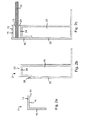
- Fig. 1a shows the upper frame member 11 of a first embodiment of the frame according to the invention.
- the upper frame member 11 has an angular cross-section, wherein on the underside of the first leg 12, the second surface 14 is formed, which is equipped with an adhesive tape 3.
- the lower frame element 21 (FIG. Fig. 1b ) has a first surface 24 which is equipped with an adhesive tape 23.
- the upper frame member 21 further includes a cavity 25 into which corner connectors (not shown) can be positively inserted to connect a plurality of lower frame members 21 together.
- Fig. 1c the frame mounted on the plate-shaped solar element 31 is shown. It can be seen that the underside of the solar element 31 in its edge region on the adhesive tape 23, which is located on the first surface 24 of the lower frame member 21 rests, whereby the bottom of the solar module 31 is bonded to the lower frame member 21.
- the upper frame element 11 is glued over the adhesive tape 13, which is located on the second surface 14, with the top of the solar module 31 in its edge region, that the second leg 15 of the upper frame member 11 rests against the outer side 22 of the lower frame member 21.
- Fig. 2a to 2c shows a second embodiment of the frame according to the invention, which is largely similar to the first embodiment.
- a recess 26 is provided in the upper region of the outer side 22 of the lower frame element 21, which adjoins the first surface 24.
- the recess 26 is dimensioned so that it can receive the second leg 15 of the upper frame member 11. In this way, a stepless outer edge of the frame is obtained.
- the remaining reference numerals have the same meaning as in the Fig. 1a to 1c , Characterized in that the lower frame member 21 having formed on the frame outside and orthogonal to the first surface 24 recess 26, a positive and / or non-positive connection is created. This non-positive connection can also be achieved by a snap or locking connection z. B. be obtained insofar as on the frame member 21 instead of the recess 26 a groove is formed, in which a bead-like portion engages the leg 15, engages or snaps, the leg should preferably have a resilient-elastic configuration
- a web 27 is provided on the lower frame member 21 extending from the first surface 24 of the lower frame member 21 toward the second surface 14 and the gap formed between the first surface 24 and the second surface 14, outwardly bounded ,
- the web 27 forms a stop edge for the plate-shaped solar element 31.
- the outside of the web 27 and the outer side 22 of the lower frame member 21 are in the region of the recess 26 preferably in a plane.
- the remaining reference numerals have the same meaning as in the Fig. 2a to 2c ,
- a fourth embodiment of the frame according to the invention is shown, in which both the lower frame member 21 (as already in the first three illustrated embodiments) and the upper frame member 11 are formed as hollow profiles.
- This allows the connection of a plurality of upper frame members 11 1 by means of positive corner joints (not shown), which are inserted into the cavities 16 of the upper frame member 11.
- the cavity 16 is obtained by forming a web 17 which is parallel to the second leg 15 and is spaced from the second leg 15 in the direction of the second surface 14.
- the web 17, which is shorter than the second leg 15, begins at the bottom of the first leg 12 and opens into a further web 18, which is parallel to the first leg 18, but shorter than this.
- the further web 18 begins at the inside of the leg 15 and ends in the web 17th
- the recess 26 of the lower frame member 21 is dimensioned so that it receives only the part of the second leg 15, which is located below the underside of the web 18.
- the lower frame member 21 further includes a recess 29 which is bounded at the bottom by a surface 24 'which is formed on the side of the web 27 which faces away from the first surface 24.
- Surface 24 and surface 24 ' are preferably in one plane.
- the extent of the surface 24 from the web 27 in the direction of the outside of the frame corresponds to the length of the web 18 of the upper frame member 11.
- the length of the web 17 of the upper frame member is less than or equal to the length of the web 27, so that the recess 29 of the edges of the upper frame member which define the opening 18, is filled.
- the web 27 may not touch the surface of the web 14.
- the gap defined by the air gap 40 is defined by the length of the leg 15, wherein between the webs 28 'and 17' also a Air gap can be formed ( Fig. 4c ).
- the outer sides of the web 27 are formed in alignment with the inner wall 28 of the lower frame member.
- a drainage channel can be formed in area A.
- drainage holes can be provided in area B.
- the remaining reference numerals have the same meaning as in the Fig. 3a to 3c ,
- Fig. 5 is a plan view of a solar module shown showing a frame according to the invention. It can be seen that the upper frame element is composed of four partial elements 11a, 11b, 11c, 11d. Likewise, the lower frame member is composed of four sub-elements (not shown).
Landscapes
- Engineering & Computer Science (AREA)
- Physics & Mathematics (AREA)
- Mechanical Engineering (AREA)
- Sustainable Development (AREA)
- Sustainable Energy (AREA)
- Thermal Sciences (AREA)
- Chemical & Material Sciences (AREA)
- Combustion & Propulsion (AREA)
- Life Sciences & Earth Sciences (AREA)
- General Engineering & Computer Science (AREA)
- Electromagnetism (AREA)
- Condensed Matter Physics & Semiconductors (AREA)
- General Physics & Mathematics (AREA)
- Computer Hardware Design (AREA)
- Microelectronics & Electronic Packaging (AREA)
- Power Engineering (AREA)
- Photovoltaic Devices (AREA)
- Manufacturing & Machinery (AREA)
- Roof Covering Using Slabs Or Stiff Sheets (AREA)
Abstract
Description
Die Erfindung betrifft einen Rahmen für ein plattenförmiges Solarelement sowie die Verwendung eines derartigen Rahmens für die Herstellung eines Solarmoduls.The invention relates to a frame for a plate-shaped solar element and the use of such a frame for the production of a solar module.
Solarmodule bestehen aus einem Rahmen, der das Solarelement, das in der Regel eine Vielzahl von Solarzellen, die in einer Ebene angeordnet und in einer Kunststofffolie eingebettet sind, umfasst. Die Kunststofffolie ist in der Regel von einer Glassplatte bedeckt und weist eine Rückseitenkaschierung auf, die üblicherweise ebenfalls aus Kunststoff besteht. Das Solarelement, das gelegentlich auch als rahmenloses Solarmodul oder Laminat bezeichnet wird, ist von einem Rahmen eingefasst, der eine Versteifung des Solarelementes bewirkt, das Solarelement, insbesondere die Glasscheibe, während des Transportes schützt, und eine Befestigung von Solarelementen auf bauliche Einrichtungen ermöglicht. Das gerahmte Solarelement wird in der Regel als Solarmodul bezeichnet.Solar modules consist of a frame, which comprises the solar element, which is usually a plurality of solar cells, which are arranged in a plane and embedded in a plastic film. The plastic film is usually covered by a glass plate and has a Rückseitenkaschierung, which is usually also made of plastic. The solar element, which is sometimes referred to as a frameless solar module or laminate is bordered by a frame which causes a stiffening of the solar element, the solar element, in particular the glass, protects during transport, and allows attachment of solar elements to building facilities. The framed solar element is usually referred to as a solar module.
Nach dem Stand der Technik werden in der Regel einteilige Rahmen verwendet. Ein solcher Rahmen wird seitlich auf die Außenkanten des Solarelementes gedrückt. Anschließend werden die Kanten des Solarmoduls manuell verklebt. Diese Verfahrensweise ist wenig effizient.In the prior art, one-piece frames are usually used. Such a frame is pressed laterally on the outer edges of the solar element. Subsequently, the edges of the solar module are glued manually. This procedure is not very efficient.
Ferner sind zweiteilige Rahmen bekannt, die ein unteres Rahmenelement umfassen, auf den das Solarelement aufgelegt wird. Der eigentliche Rahmen wird erhalten, indem ein oberes Rahmenelement in das untere Rahmenelement unter Erhalt einer kraft- oder formschlüssigen Verbindung eingepresst wird, wobei zwischen dem unteren und dem oberen Rahmenelement ein Spalt ausgebildet wird, in den Randbereich des Solarelementes eingeführt wird.Furthermore, two-part frames are known which comprise a lower frame member on which the solar element is placed. The actual frame is obtained by pressing an upper frame member into the lower frame member to obtain a positive or positive connection, wherein a gap is formed between the lower and the upper frame member, is inserted into the edge portion of the solar element.
Aufgabe der Erfindung ist es, die Nachteile nach dem Stand der Technik zu beseitigen. Es soll insbesondere ein Rahmen zur Aufnahme eines plattenförmigen Solarelementes angegeben werden, der eine effizientere und kostengünstigere Rahmung von Solarelementen ermöglicht.The object of the invention is to eliminate the disadvantages of the prior art. It should in particular be given a frame for receiving a plate-shaped solar element, which allows a more efficient and cost-effective framing of solar elements.
Diese Aufgabe wird durch die Merkmale der Ansprüche 1 und 13 gelöst. Zweckmäßige Ausgestaltungen der Erfindung ergeben sich aus den Merkmalen der Ansprüche 2 bis 12 und 14.This object is solved by the features of
Nach Maßgabe der Erfindung ist ein Rahmen für ein plattenförmiges Solarelement vorgesehen, der ein unteres Rahmenelement mit einer ersten Fläche und bevorzugterweise ein oberes Rahmenelement mit einer zweiten Fläche umfasst, wobei die zweite Fläche der ersten Fläche gegenüberliegt und von dieser unter Ausbildung einer Spaltes beabstandet ist, der den Randbereich des plattenförmigen Solarelementes aufnehmen kann, wobei die erste Fläche und die zweite Fläche jeweils selbstklebend ausgerüstet sind. Vorzugsweise ist dabei die erste Fläche mit einem ersten Klebeband und die zweite Fläche mit einem zweiten Klebeband ausgerüstet. Der Rahmen kann auch nur ein unteres Rahmenelement mit einer zweiten Fläche umfassen, wohingegen ein oberes Rahmenelement entfallen kann.According to the invention, a frame is provided for a plate-shaped solar element comprising a lower frame member having a first surface and preferably an upper frame member having a second surface, the second surface being opposite the first surface and being spaced therefrom to form a gap, which can receive the edge region of the plate-shaped solar element, wherein the first surface and the second surface are each equipped with self-adhesive. Preferably, the first surface is equipped with a first adhesive tape and the second surface with a second adhesive tape. The frame may also comprise only a lower frame member having a second surface, whereas an upper frame member may be omitted.
Das erste und das zweite Klebeband sind zweckmäßigerweise doppelseitige Klebebänder, vorzugsweise doppelseitige Schaumklebebänder. Dabei weist das doppelseitige Klebeband, mit dem die erste Fläche ausgerüstet ist (erstes doppelseitiges Klebeband), eine innere Kleberschicht auf, die in Kontakt mit der ersten Fläche steht, während die äußere Kleberschicht der zweiten Fläche des oberen Rahmenelementes zugewandt ist. Das doppelseitige Klebeband, mit dem die zweite Fläche ausgerüstet ist (zweites doppelseitiges Klebeband), weist ebenfalls eine innere Kleberschicht auf, die in Kontakt mit der zweiten Fläche steht, während die äußere Kleberschicht der ersten Fläche des unteren Rahmenelementes zugewandt ist.The first and the second adhesive tape are expediently double-sided adhesive tapes, preferably double-sided foam adhesive tapes. In this case, the double-sided adhesive tape with which the first surface is equipped (first double-sided adhesive tape), an inner adhesive layer which is in contact with the first surface, while the outer adhesive layer faces the second surface of the upper frame member. The double-sided adhesive tape with which the second surface is provided (second double-sided adhesive tape) also has an inner adhesive layer in contact with the second surface while the outer adhesive layer faces the first surface of the lower frame member.
Das erste und das zweite Rahmenelement können aus demselben oder unterschiedlichen Materialien bestehen. Nach einer bevorzugten Ausführungsform bestehen das untere und das obere Rahmenelement aus einem witterungsbeständigen Material, wie beispielsweise Aluminium, oder anderen geeigneten Materialien.The first and second frame members may be made of the same or different materials. In a preferred embodiment, the lower and upper frame members are made of a weather-resistant material, such as aluminum, or other suitable materials.
Unter einem Solarelement wird hier das Laminat, das die Solarzellen umfasst, verstanden. Das Solarelement ist rahmenlos. Unter einem Solarmodul wird hier das gerahmte Solarelement, also das Solarelement, das in den Rahmen eingesetzt ist, verstanden.Under a solar element here is the laminate, which includes the solar cells understood. The solar element is frameless. Under a solar module here the framed solar element, so the solar element, which is inserted into the frame understood.
Der erfindungsgemäße, zweiteilige Rahmen ermöglicht aufgrund der Ausrüstung der beiden Flächen, die in Kontakt mit dem Randbereich des plattenförmigen Solarelementes gelangen, den Verzicht einerseits auf eine Dichtung und andererseits auf eine manuelle Verklebung. Damit entfallen aufwendige und unhandliche Verklebungsprozesse direkt auf dem Solarmodul vollständig, was die Montage des Solarelementes in einen Rahmen erheblich vereinfacht. Die beiden Klebebänder übernehmen zusätzlich zur Abdichtung des Solarmoduls gegen Witterungseinflüsse die Funktion der Verbindung zwischen oberem und unterem Rahmenelement, wobei der klebende Kraftschluss über das Solarelement entsteht. Außerdem können die beiden Rahmenelemente durch eine optionale form- und/oder kraftschlüssige Verbindung zusätzlich miteinander verbunden werden. Der Montage-Vorgang wird durch den erfindungsgemäßen Rahmen so vereinfacht, dass neben der aktuell üblichen Montage innerhalb der Produktionshallen nun auch sogar eine Montage vor Ort denkbar ist. Dabei wird zuerst das untere Rahmenelement am Bestimmungsort fest montiert und danach das Solarelement und das obere Rahmenelement wie nachstehend beschrieben zusammengesetzt.The two-part frame according to the invention, due to the equipment of the two surfaces, which come into contact with the edge region of the plate-shaped solar element, the renunciation on the one hand to a seal and on the other hand to a manual bonding. This eliminates complex and unwieldy bonding processes directly on the solar module completely, which greatly simplifies the installation of the solar element in a frame. The two tapes take over in addition to the sealing of the solar module against weathering the function of the connection between the upper and lower frame member, wherein the adhesive adhesion occurs on the solar element. In addition, the two frame members can be additionally connected to each other by an optional positive and / or non-positive connection. The assembly process is simplified by the frame according to the invention so that in addition to the current customary assembly within the production halls now even an assembly on site is conceivable. At first, the lower frame member is fixedly mounted at the destination, and then the solar element and the upper frame member are assembled as described below.
Die beiden Rahmenelemente werden bereits während ihrer Herstellung mit dem Klebeband ausgerüstet, wobei die Oberfläche der ersten und der zweiten Kleberschicht, die sich nicht in Kontakt mit der ersten bzw. zweiten Fläche befindet, mit jeweils einer Abdeckung versehen ist. Diese Abdeckungen werden erst bei der Montage des Solarmoduls entfernt.The two frame elements are already equipped with the adhesive tape during their production, the surface of the first and the second adhesive layer, which is not in contact with the first or second surface, being provided with a respective cover. These covers are removed only during installation of the solar module.
Zur Herstellung des Solarmoduls wird zunächst die Abdeckung von der Kleberschicht entfernt, die sich auf der ersten Fläche des unteren Rahmenelementes befindet. Dann wird die Unterseite des plattenförmigen Solarelementes in dessen Randbereich auf die Kleberschicht, die sich auf der ersten Fläche des unteren Rahmenelementes befindet, aufgelegt, wodurch eine Klebeverbindung zwischen dem unteren Rahmenelement und der Solarelemente ausgebildet wird. Anschließend wird das obere Rahmenelement derart auf das plattenförmige Solarelement aufgebracht, dass die Kleberschicht, die sich auf der zweiten Fläche des oberen Rahmenelementes befindet und von der zuvor die Abdeckung entfernt worden ist, in Kontakt mit der Oberseite des plattenförmigen Solarelementes in dessen Randbereich gelangt. Dabei wird eine Klebeverbindung zwischen dem oberen Rahmenelement und dem Solarelement ausgebildet.For the production of the solar module, first the cover is removed from the adhesive layer which is located on the first surface of the lower frame element. Then, the underside of the plate-shaped solar element in the edge region of the Adhesive layer, which is located on the first surface of the lower frame member, placed, whereby an adhesive bond between the lower frame member and the solar elements is formed. Subsequently, the upper frame member is applied to the plate-shaped solar element such that the adhesive layer, which is located on the second surface of the upper frame member and has previously been removed from the cover, comes into contact with the top of the plate-shaped solar element in its edge region. In this case, an adhesive connection between the upper frame member and the solar element is formed.
Ist das plattenförmige Solarelement in den Rahmen eingelegt, so befindet sich die Unterseite des plattenförmiges Solarelementes in dessen Randbereich in Kontakt mit der Kleberschicht des ersten Klebebandes und die Oberseite des Solarmoduls in dessen Randbereich in Kontakt mit der Kleberschicht des zweiten Klebebandes.If the plate-shaped solar element is inserted into the frame, then the underside of the plate-shaped solar element is in contact with the adhesive layer of the first adhesive tape in its edge region and the top side of the solar module in the edge region in contact with the adhesive layer of the second adhesive tape.
Vorzugsweise weist das untere Rahmenelement eine Anschlagkante für das plattenförmige Solarelement auf, die sich von der ersten Fläche in Richtung der zweiten Fläche erstreckt und den Spalt, der zwischen der ersten Fläche und der zweiten Fläche ausgebildet ist, nach außen hin begrenzt. Die Anschlagkante ermöglicht eine genaue Positionierung des Solarelementes auf der zweiten Oberfläche.Preferably, the lower frame member has a stop edge for the plate-shaped solar member extending from the first surface toward the second surface and defining the gap formed between the first surface and the second surface toward the outside. The stop edge allows accurate positioning of the solar element on the second surface.
Ferner kann das untere Rahmenelement eine Ausnehmung, die an der Rahmenaußenseite und orthogonal zur erste Fläche ausgebildet ist, und das obere Rahmenelement einen Schenkel aufweisen, der in die Ausnehmung unter Erhalt einer form- und oder kraftschlüssigen Verbindung eingeführt werden kann, wobei der Schenkel orthogonal zur zweiten Fläche des oberen Rahmenelementes ausgebildet ist und sich von dieser in Richtung des unteren Rahmenelementes erstreckt. Auf diese Weise wird eine glatte Außenkante des Rahmens erreicht.Further, the lower frame member may have a recess formed on the frame outside and orthogonal to the first surface, and the upper frame member has a leg which can be inserted into the recess to form a positive and / or non-positive connection, wherein the leg orthogonal to second surface of the upper frame member is formed and extends from the latter in the direction of the lower frame member. In this way, a smooth outer edge of the frame is achieved.
Zweckmäßigerweise sind sowohl das untere Rahmenelement als auch das obere Rahmenelement jeweils aus Teilelementen zusammengesetzt, wobei die Teilelemente mittels Verbindungselementen miteinander verbunden sind. Typischerweise ist das plattenförmige Solarelement rechteckig, so dass das untere und das obere Rahmenelement jeweils aus vier Teilelementen zusammengesetzt ist, wobei benachbarte Teilelemente des jeweiligen Rahmenelementes rechtwinklig zueinander angeordnet sind. Die Teilelemente sind vorzugsweise Profilelemente, die Profilhohlräume aufweisen. Zur Verbindung benachbarter Teilelemente sind Verbindungselemente, beispielsweise handelsübliche Eckverbindungen, vorgesehen, die formschlüssig in die Profilhohlräume eingesteckt werden können. Die Kontur der ersten Fläche des unteren Rahmenelementes und die Kontur der zweiten Fläche des oberen Rahmenelementes entsprechen somit dem Randbereich des Solarelementes. Die Profilelemente sind bevorzugt vorkonfektionierte, auf Gehrung und vorgegebene Länge geschnittene Profilelemente, so dass eine Montage des Rahmens sehr einfach möglich ist. Ferner sind sämtliche notwendigen Bohrungen, wie sie beispielsweise zur Montage eines Solarmoduls auf baulichen Anlagen benötigt werden, in die beiden Rahmenelemente bereits eingebracht. Die Aufbringung der selbstklebenden Ausrüstung, insbesondere der beiden Klebebänder kann in einem automatisierten Verfahren erfolgen.Conveniently, both the lower frame member and the upper frame member are each composed of sub-elements, wherein the sub-elements are interconnected by means of connecting elements. Typically, the plate-shaped solar element is rectangular, so that the lower and the upper frame member is each composed of four sub-elements, wherein adjacent sub-elements of the respective frame element are arranged at right angles to each other. The sub-elements are preferably profile elements having profile cavities. To connect neighboring Partial elements are connecting elements, for example commercially available corner joints, provided that can be positively inserted into the profile cavities. The contour of the first surface of the lower frame member and the contour of the second surface of the upper frame member thus correspond to the edge region of the solar element. The profile elements are preferably prefabricated, mitred and predetermined length cut profile elements, so that an assembly of the frame is very easy. Furthermore, all necessary holes, such as those required for mounting a solar module on structures, already introduced into the two frame elements. The application of the self-adhesive equipment, in particular the two adhesive tapes can be done in an automated process.
Zur Abführung von Wasser kann zwischen dem unteren Rahmenelement und dem oberen Rahmenelement ein Drainagekanal ausgebildet sein. Vorzugsweise ist die Unterseite des Drainagekanals von einer Rille gebildet, die in einem Bereich der ersten Fläche des unteren Rahmenelementes ausgebildet ist, der nicht von dem ersten doppelseitigen Klebeband bedeckt ist und von diesem in Richtung der Rahmenaußenkante beabstandet ist. Der Drainagekanal hat zwei wesentliche Funktionen: zum einen den Ausgleich von unterschiedlichen Ausdehnungen der Bauteile bei schwankenden Temperaturen und zum anderen die Abführung von gegebenenfalls eindringender Feuchtigkeit. Ferner können im unteren Rahmenelement und/oder im oberen Rahmenelement Drainagebohrungen ausgebildet sein.For the discharge of water, a drainage channel may be formed between the lower frame member and the upper frame member. Preferably, the underside of the drainage channel is formed by a groove formed in a portion of the first surface of the lower frame member which is not covered by the first double-sided adhesive tape and spaced therefrom toward the frame outer edge. The drainage channel has two essential functions: on the one hand the compensation of different expansions of the components at fluctuating temperatures and on the other hand the removal of any penetrating moisture. Furthermore, drainage bores can be formed in the lower frame element and / or in the upper frame element.
Nach Maßgabe der Erfindung ist ferner die Verwendung des erfindungsgemäßen Rahmens zur Herstellung eines Solarmoduls vorgesehen. Zur Montage des Solarmoduls wird dabei wie folgt vorgegangen: Nach der Montage des unteren Rahmenelementes aus den Teilelementen wird die Abdeckung des ersten Klebebandes entfernt und das Solarelement von oben auf die erste Fläche gelegt. Die korrekte, reproduzierbare Positionierung erfolgt vorzugsweise mittels der Anschlagkante, die sicherstellt, dass das Solarelement nicht an einer falschen Position mit dem unteren Rahmenelement verklebt ist. Danach wird das fertig montierte obere Rahmenelement von oben auf den unteren Rahmen mit dem Solarelement geschoben. Vorher wurde auch hier die Abdeckung von dem zweiten Klebeband entfernt.According to the invention, the use of the frame according to the invention for the production of a solar module is also provided. To install the solar module, the procedure is as follows: After mounting the lower frame member from the sub-elements, the cover of the first adhesive tape is removed and placed the solar element from above on the first surface. The correct, reproducible positioning is preferably by means of the stop edge, which ensures that the solar element is not glued in a wrong position with the lower frame member. Thereafter, the finished mounted upper frame member is pushed from above onto the lower frame with the solar element. Previously, the cover was removed from the second tape here as well.
Die Erfindung wird nachstehend anhand von Zeichnungen näher erläutert. Dabei zeigen
- Fig. 1a
- eine Schnittdarstellung eines Teilelementes des oberen Rahmenelementes gemäß einer ersten Ausführungsform des erfindungsgemäßen Rahmens;
- Fig. 1b
- eine Schnittdarstellung eines Teilelementes des unteren Rahmenelementes gemäß der ersten Ausführungsform des erfindungsgemäßen Rahmens;
- Fig. 1c
- eine Schnittdarstellung des unteren und des oberen Rahmenelementes gemäß der ersten Ausführungsform gemeinsam mit dem Solarelement nach der Montage zum Solarmodul;
- Fig. 2a
- eine Schnittdarstellung eines Teilelementes des oberen Rahmenelementes gemäß einer zweiten Ausführungsform des erfindungsgemäßen Rahmens;
- Fig. 2b
- eine Schnittdarstellung eines Teilelementes des unteren Rahmenelementes gemäß der zweiten Ausführungsform des erfindungsgemäßen Rahmens;
- Fig. 2c
- eine Schnittdarstellung des unteren und des oberen Rahmenelementes gemäß der zweiten Ausführungsform gemeinsam mit dem Solarelement nach der Montage zum Solarmodul;
- Fig. 3a
- eine Schnittdarstellung eines Teilelementes des oberen Rahmenelementes gemäß einer dritten Ausführungsform des erfindungsgemäßen Rahmens;
- Fig. 3b
- eine Schnittdarstellung eines Teilelementes des unteren Rahmenelementes gemäß der dritten Ausführungsform des erfindungsgemäßen Rahmens;
- Fig. 3c
- eine Schnittdarstellung des unteren und des oberen Rahmenelementes gemäß der dritten Ausführungsform gemeinsam mit dem Solarelement nach der Montage zum Solarmodul;
- Fig. 4a
- eine Schnittdarstellung eines Teilelementes des oberen Rahmenelementes gemäß einer vierten Ausführungsform des erfindungsgemäßen Rahmens;
- Fig. 4b
- eine Schnittdarstellung eines Teilelementes des unteren Rahmenelementes gemäß der vierten Ausführungsform des erfindungsgemäßen Rahmens;
- Fig. 4c
- eine Schnittdarstellung des unteren und des oberen Rahmenelementes gemäß der vierten Ausführungsform gemeinsam mit dem Solarelement nach der Montage zum Solarmodul; und
- Fig. 5
- eine Draufsicht auf das Solarmodul.
- Fig. 1a
- a sectional view of a sub-element of the upper frame member according to a first embodiment of the frame according to the invention;
- Fig. 1b
- a sectional view of a sub-element of the lower frame member according to the first embodiment of the frame according to the invention;
- Fig. 1c
- a sectional view of the lower and upper frame member according to the first embodiment together with the solar element after mounting to the solar module;
- Fig. 2a
- a sectional view of a sub-element of the upper frame member according to a second embodiment of the frame according to the invention;
- Fig. 2b
- a sectional view of a sub-element of the lower frame member according to the second embodiment of the frame according to the invention;
- Fig. 2c
- a sectional view of the lower and the upper frame member according to the second embodiment together with the solar element after mounting to the solar module;
- Fig. 3a
- a sectional view of a sub-element of the upper frame member according to a third embodiment of the frame according to the invention;
- Fig. 3b
- a sectional view of a sub-element of the lower frame member according to the third embodiment of the frame according to the invention;
- Fig. 3c
- a sectional view of the lower and upper frame member according to the third embodiment, together with the solar element after mounting to the solar module;
- Fig. 4a
- a sectional view of a sub-element of the upper frame member according to a fourth embodiment of the frame according to the invention;
- Fig. 4b
- a sectional view of a sub-element of the lower frame member according to the fourth embodiment of the frame according to the invention;
- Fig. 4c
- a sectional view of the lower and upper frame member according to the fourth embodiment, together with the solar element after mounting to the solar module; and
- Fig. 5
- a plan view of the solar module.
Das untere Rahmenelement 21 (
In
In den
Bei der dritten Ausführungsform des erfindungsgemäßen Rahmens, die in den
In den
Abweichend von den ersten drei dargestellten Ausführungsformen ist die Ausnehmung 26 des unteren Rahmenelementes 21 so dimensioniert, dass sie nur den Teil des zweiten Schenkels 15 aufnimmt, der sich unterhalb der Unterseite des Steges 18 befindet. Das untere Rahmenelement 21 weist ferner eine Ausnehmung 29 auf, die nach unten hin von einer Fläche 24' begrenzt wird, die auf der Seite des Steges 27 ausgebildet ist, die der ersten Fläche 24 abgewandt ist. Fläche 24 und Fläche 24' liegen bevorzugt in einer Ebene. Die Ausdehnung der Fläche 24 vom Steg 27 in Richtung der Außenseite des Rahmens entspricht dabei der Länge des Steges 18 des oberen Rahmenelementes 11. Die Länge des Steges 17 des oberen Rahmenelementes ist kleiner oder gleich der Länge des Steges 27, so dass die Ausnehmung 29 von den Kanten des oberen Rahmenelementes, die die Öffnung 18 begrenzen, ausgefüllt wird. Der Steg 27 darf die Fläche des Steges 14 nicht berühren. Das durch den Luftspalt 40 festgelegte Spaltmaß wird durch die Länge des Schenkels 15 definiert, wobei zwischen den Stegen 28' und 17' auch ein Luftspalt ausgebildet sein kann (
In
- 1111
- oberes RahmenelementUpper frame element
- 11a, 11b, 11c, 11d11a, 11b, 11c, 11d
- Teilelemente des oberen RahmenelementesPartial elements of the upper frame element
- 1212
- erster Schenkel des oberen Rahmenelementesfirst leg of the upper frame member
- 1313
- zweites Klebebandsecond tape
- 1414
- zweite Fläche des oberen Rahmenelementessecond surface of the upper frame element
- 1515
- zweiter Schenkel des oberen Rahmenelementessecond leg of the upper frame member
- 1616
- Hohlraum im oberen RahmenelementCavity in the upper frame element
- 1717
- senkrechter Stegvertical bridge
- 1818
- waagegerechter Steglevel bridge
- 2121
- unteres Rahmenelementlower frame element
- 2222
- Außenseite des unteren RahmenelementesOutside of the lower frame element
- 2323
- zweites Klebebandsecond tape
- 2424
- erste Fläche des unteren Rahmenelementesfirst surface of the lower frame element
- 24'24 '
-
Fläche in einer Ebene mit Fläche 24Surface in a plane with
surface 24 - 2525
- Hohlraum im unteren RahmenelementCavity in the lower frame element
- 2626
- Ausnehmung an der Außenseite des unteren RahmenelementesRecess on the outside of the lower frame member
- 2727
- Steg als Anschlagkante für das Solarelement 31Web as a stop edge for the solar element 31st
- 2828
- Innenwandinner wall
- 2929
- Ausnehmung oberhalb von Fläche 24'Recess above surface 24 '
- 3131
- Solarelementsolar element
Claims (14)
Applications Claiming Priority (1)
| Application Number | Priority Date | Filing Date | Title |
|---|---|---|---|
| DE102008031545A DE102008031545A1 (en) | 2008-07-07 | 2008-07-07 | Frame for a plate-shaped solar element |
Publications (3)
| Publication Number | Publication Date |
|---|---|
| EP2144300A2 true EP2144300A2 (en) | 2010-01-13 |
| EP2144300A3 EP2144300A3 (en) | 2013-03-13 |
| EP2144300B1 EP2144300B1 (en) | 2018-08-08 |
Family
ID=41226162
Family Applications (1)
| Application Number | Title | Priority Date | Filing Date |
|---|---|---|---|
| EP09162975.8A Not-in-force EP2144300B1 (en) | 2008-07-07 | 2009-06-17 | Framework for a plate-shaped solar element |
Country Status (8)
| Country | Link |
|---|---|
| US (2) | US20100000521A1 (en) |
| EP (1) | EP2144300B1 (en) |
| JP (1) | JP2010016385A (en) |
| KR (1) | KR20100005692A (en) |
| CN (1) | CN101626038A (en) |
| CA (1) | CA2666299A1 (en) |
| DE (1) | DE102008031545A1 (en) |
| TW (1) | TWI464353B (en) |
Families Citing this family (11)
| Publication number | Priority date | Publication date | Assignee | Title |
|---|---|---|---|---|
| JP5598003B2 (en) * | 2010-01-29 | 2014-10-01 | 凸版印刷株式会社 | Solar cell module |
| TWM395145U (en) * | 2010-02-10 | 2010-12-21 | De Poan Pneumatic Corp | Corner connection device of frame used for embedding solar panel |
| CN103109450A (en) * | 2010-09-20 | 2013-05-15 | 美国圣戈班性能塑料公司 | Self-adhesive frame |
| ITRM20110435A1 (en) * | 2011-08-10 | 2013-02-11 | Stefano Luigi Di | FORCED AIR CIRCULATION EQUIPMENT FOR COOLING PHOTOVOLTAIC SOLAR PANELS IN OPERATION |
| TWM426878U (en) * | 2011-11-25 | 2012-04-11 | Hulk Energy Technology Co Ltd | Frame structure of solar energy module |
| CN103208543B (en) * | 2013-03-22 | 2015-08-05 | 友达光电股份有限公司 | Solar energy module |
| US10289604B2 (en) * | 2014-08-07 | 2019-05-14 | Wisconsin Alumni Research Foundation | Memory processing core architecture |
| JP6359125B2 (en) * | 2015-01-29 | 2018-07-18 | 京セラ株式会社 | Solar cell module |
| CN105680784B (en) * | 2016-04-19 | 2018-05-01 | 河南水木环保科技股份有限公司 | The reinforcement means of double glass solar energy photovoltaic panel ruggedized constructions |
| WO2019191691A1 (en) | 2018-03-30 | 2019-10-03 | Sunpower Corporation | Single-walled connecting key framesets |
| JPWO2022085367A1 (en) * | 2020-10-19 | 2022-04-28 |
Citations (1)
| Publication number | Priority date | Publication date | Assignee | Title |
|---|---|---|---|---|
| DE20209218U1 (en) | 2002-06-07 | 2002-10-24 | Conergy Systems Gmbh | Attachment for a solar module (snap-in - assembly module) |
Family Cites Families (25)
| Publication number | Priority date | Publication date | Assignee | Title |
|---|---|---|---|---|
| DE2546069A1 (en) | 1975-10-15 | 1977-04-21 | Abel Konrad Dipl Ing Prof | Radiation collector for solar energy - has support tray extended at sides to provide edge insulation round absorber |
| DE2650144A1 (en) | 1976-10-30 | 1978-05-03 | Rheinisches Zinkwalzwerk Gmbh | CLAMPING FRAME FOR SOLAR COLLECTORS |
| DE7634735U1 (en) | 1976-11-02 | 1979-11-29 | Reinhard, Sigrid, Dipl.-Ing., 2803 Kirchweyhe | SOLAR ENERGY COLLECTOR |
| DE2847176C2 (en) | 1977-10-31 | 1982-05-06 | Hitachi, Ltd., Tokyo | Method for the photometric determination of substances in blood serum |
| FR2448696A1 (en) | 1979-02-06 | 1980-09-05 | Pinauldt Jacques | SOLAR CAPTOR |
| US4454703A (en) * | 1981-11-12 | 1984-06-19 | Solar Structures Corp. | Solar panel |
| DE3611545A1 (en) * | 1986-04-05 | 1987-10-08 | Remscheid Volksbank | Solar module |
| AU661184B2 (en) * | 1992-09-07 | 1995-07-13 | Hirai Engineering Corporation | Roof apparatus |
| US5478402A (en) * | 1994-02-17 | 1995-12-26 | Ase Americas, Inc. | Solar cell modules and method of making same |
| AT337U1 (en) | 1994-11-07 | 1995-08-25 | Thaller Herbert | SOLAR ENERGY ROOF |
| US5836117A (en) * | 1995-07-28 | 1998-11-17 | Johnson; Flint Scott | Building extension |
| US5762720A (en) * | 1996-06-27 | 1998-06-09 | Evergreen Solar, Inc. | Solar cell modules with integral mounting structure and methods for forming same |
| JPH11103086A (en) * | 1997-07-29 | 1999-04-13 | Kanegafuchi Chem Ind Co Ltd | Solar battery module |
| DE29804410U1 (en) | 1998-03-12 | 1998-05-14 | Senghas Werner | Solar collector device |
| JP2000226909A (en) * | 1999-02-08 | 2000-08-15 | Sekisui Chem Co Ltd | Roof tile with solar battery |
| DE10000856C2 (en) | 2000-01-12 | 2002-01-31 | Auber Hans Joerg | Flat design solar panel |
| DE20109727U1 (en) | 2001-03-27 | 2001-09-20 | Ufe Solar Gmbh | Solar collector |
| US6662523B2 (en) * | 2001-06-15 | 2003-12-16 | Sashlite, Llc | Insulating glass sash assemblies with adhesive mounting and spacing structures |
| JP2005076340A (en) * | 2003-09-02 | 2005-03-24 | Shinsei Shoji Kk | Roof material with solar panel |
| EP1548846A3 (en) * | 2003-11-28 | 2007-09-19 | Sharp Kabushiki Kaisha | Solar cell module edge face sealing member and solar cell module employing same |
| JP2006132111A (en) * | 2004-11-02 | 2006-05-25 | Sekisui Chem Co Ltd | Support tool of solar battery panel and support structure of solar battery panel |
| US7956279B2 (en) * | 2005-03-18 | 2011-06-07 | Kyocera Corporation | Solar cell module and solar cell array |
| CA2633025A1 (en) * | 2007-05-30 | 2008-11-30 | Gordon Hogan | Solar panel |
| MX2010005945A (en) * | 2007-12-04 | 2011-03-03 | Parabel Ag | Multilayer solar element. |
| US8590222B2 (en) * | 2010-10-05 | 2013-11-26 | Alexander Koller | Support arrangement |
-
2008
- 2008-07-07 DE DE102008031545A patent/DE102008031545A1/en not_active Withdrawn
-
2009
- 2009-05-21 CA CA002666299A patent/CA2666299A1/en not_active Abandoned
- 2009-06-17 EP EP09162975.8A patent/EP2144300B1/en not_active Not-in-force
- 2009-06-18 TW TW098120392A patent/TWI464353B/en not_active IP Right Cessation
- 2009-06-23 US US12/490,003 patent/US20100000521A1/en not_active Abandoned
- 2009-07-06 JP JP2009160018A patent/JP2010016385A/en not_active Withdrawn
- 2009-07-07 KR KR1020090061692A patent/KR20100005692A/en not_active Application Discontinuation
- 2009-07-07 CN CN200910158754A patent/CN101626038A/en active Pending
-
2014
- 2014-05-05 US US14/269,310 patent/US9391222B2/en active Active
Patent Citations (1)
| Publication number | Priority date | Publication date | Assignee | Title |
|---|---|---|---|---|
| DE20209218U1 (en) | 2002-06-07 | 2002-10-24 | Conergy Systems Gmbh | Attachment for a solar module (snap-in - assembly module) |
Also Published As
| Publication number | Publication date |
|---|---|
| DE102008031545A1 (en) | 2010-01-14 |
| TWI464353B (en) | 2014-12-11 |
| US20140237933A1 (en) | 2014-08-28 |
| EP2144300A3 (en) | 2013-03-13 |
| TW201003017A (en) | 2010-01-16 |
| KR20100005692A (en) | 2010-01-15 |
| US20100000521A1 (en) | 2010-01-07 |
| CN101626038A (en) | 2010-01-13 |
| JP2010016385A (en) | 2010-01-21 |
| US9391222B2 (en) | 2016-07-12 |
| EP2144300B1 (en) | 2018-08-08 |
| CA2666299A1 (en) | 2010-01-07 |
Similar Documents
| Publication | Publication Date | Title |
|---|---|---|
| EP2144300B1 (en) | Framework for a plate-shaped solar element | |
| DE2810517A1 (en) | FLIGHT AND SEALING DEVICE | |
| AT505453A1 (en) | COVERING DEVICE FOR FLOOR COVERS | |
| DE102009041344A1 (en) | Window arrangement, has glass edge composite cover covering glazing and L-shaped profile section at outer boundary regions, and sealing frame locking section and projection forming water separating edge | |
| DE112020002231T5 (en) | Interior frame for door and window waterproofing, door and window with this interior frame and method of manufacturing the same | |
| EP3121358B1 (en) | Frame piece and membrane frame made therefrom | |
| EP1956174B1 (en) | Profile rail for positioning a fastening element and method for manufacturing a multi-glazing unit | |
| AT501199A1 (en) | TWO-PIECE LAYOUT CONNECTION PROFILE FOR COMPONENTS TO BE ADJUSTED TO PUTZ | |
| EP2588698B1 (en) | Spacer for dimensioning joints when clamping or sealing flat elements to profiled elements | |
| DE102010009376A1 (en) | Plaster end profile for use as plaster base at e.g. ceiling wall of building, has joint sealing tape producing connection to one wall, which is connected with outer side of one leg directed towards wall | |
| EP0746658B1 (en) | Insulating arrangement for facades | |
| DE102011007873B4 (en) | sealing tape | |
| DE3408995C2 (en) | Corner connection for profile parts | |
| AT517223B1 (en) | Joint seal between insulation elements for building insulation | |
| EP2463471B1 (en) | Method for connecting wall sections | |
| DE102007015988B4 (en) | Coupling fold block for connecting individual frames to a window front | |
| DE102016120279A1 (en) | Sealing element and method for sealing a window sill | |
| DE10225535B4 (en) | Planked wooden frames | |
| EP4245957A1 (en) | Door frame with threshold | |
| DE202021104208U1 (en) | Sealing element | |
| DE102019128665A1 (en) | Capillary protection tape | |
| EP2644792A1 (en) | Device for connecting wall sections, in particular glass elements | |
| DE3610409C2 (en) | ||
| DE102007025153B4 (en) | Frame for insulating glass panes | |
| EP0790382A1 (en) | Building element with sealing membrane and its assembly method |
Legal Events
| Date | Code | Title | Description |
|---|---|---|---|
| PUAI | Public reference made under article 153(3) epc to a published international application that has entered the european phase |
Free format text: ORIGINAL CODE: 0009012 |
|
| AK | Designated contracting states |
Kind code of ref document: A2 Designated state(s): AT BE BG CH CY CZ DE DK EE ES FI FR GB GR HR HU IE IS IT LI LT LU LV MC MK MT NL NO PL PT RO SE SI SK TR |
|
| PUAL | Search report despatched |
Free format text: ORIGINAL CODE: 0009013 |
|
| AK | Designated contracting states |
Kind code of ref document: A3 Designated state(s): AT BE BG CH CY CZ DE DK EE ES FI FR GB GR HR HU IE IS IT LI LT LU LV MC MK MT NL NO PL PT RO SE SI SK TR |
|
| AX | Request for extension of the european patent |
Extension state: AL BA RS |
|
| RIC1 | Information provided on ipc code assigned before grant |
Ipc: F24J 2/52 20060101ALI20130207BHEP Ipc: F24J 2/46 20060101ALI20130207BHEP Ipc: H01L 31/042 20060101AFI20130207BHEP |
|
| 17P | Request for examination filed |
Effective date: 20130913 |
|
| RBV | Designated contracting states (corrected) |
Designated state(s): AT BE BG CH CY CZ DE DK EE ES FI FR GB GR HR HU IE IS IT LI LT LU LV MC MK MT NL NO PL PT RO SE SI SK TR |
|
| RAP1 | Party data changed (applicant data changed or rights of an application transferred) |
Owner name: TESA SE |
|
| 17Q | First examination report despatched |
Effective date: 20160606 |
|
| STAA | Information on the status of an ep patent application or granted ep patent |
Free format text: STATUS: EXAMINATION IS IN PROGRESS |
|
| REG | Reference to a national code |
Ref country code: DE Ref legal event code: R079 Ref document number: 502009015160 Country of ref document: DE Free format text: PREVIOUS MAIN CLASS: H01L0031042000 Ipc: F24S0025000000 |
|
| GRAP | Despatch of communication of intention to grant a patent |
Free format text: ORIGINAL CODE: EPIDOSNIGR1 |
|
| STAA | Information on the status of an ep patent application or granted ep patent |
Free format text: STATUS: GRANT OF PATENT IS INTENDED |
|
| RIC1 | Information provided on ipc code assigned before grant |
Ipc: F24S 25/00 20180101AFI20180222BHEP |
|
| INTG | Intention to grant announced |
Effective date: 20180314 |
|
| RIN1 | Information on inventor provided before grant (corrected) |
Inventor name: SCHWERTFEGER, MICHAEL Inventor name: GASSNER, THOMAS |
|
| GRAS | Grant fee paid |
Free format text: ORIGINAL CODE: EPIDOSNIGR3 |
|
| GRAA | (expected) grant |
Free format text: ORIGINAL CODE: 0009210 |
|
| STAA | Information on the status of an ep patent application or granted ep patent |
Free format text: STATUS: THE PATENT HAS BEEN GRANTED |
|
| AK | Designated contracting states |
Kind code of ref document: B1 Designated state(s): AT BE BG CH CY CZ DE DK EE ES FI FR GB GR HR HU IE IS IT LI LT LU LV MC MK MT NL NO PL PT RO SE SI SK TR |
|
| REG | Reference to a national code |
Ref country code: GB Ref legal event code: FG4D Free format text: NOT ENGLISH |
|
| REG | Reference to a national code |
Ref country code: CH Ref legal event code: EP Ref country code: AT Ref legal event code: REF Ref document number: 1027454 Country of ref document: AT Kind code of ref document: T Effective date: 20180815 |
|
| REG | Reference to a national code |
Ref country code: IE Ref legal event code: FG4D Free format text: LANGUAGE OF EP DOCUMENT: GERMAN |
|
| REG | Reference to a national code |
Ref country code: DE Ref legal event code: R096 Ref document number: 502009015160 Country of ref document: DE |
|
| REG | Reference to a national code |
Ref country code: NL Ref legal event code: MP Effective date: 20180808 |
|
| REG | Reference to a national code |
Ref country code: LT Ref legal event code: MG4D |
|
| PG25 | Lapsed in a contracting state [announced via postgrant information from national office to epo] |
Ref country code: SE Free format text: LAPSE BECAUSE OF FAILURE TO SUBMIT A TRANSLATION OF THE DESCRIPTION OR TO PAY THE FEE WITHIN THE PRESCRIBED TIME-LIMIT Effective date: 20180808 Ref country code: IS Free format text: LAPSE BECAUSE OF FAILURE TO SUBMIT A TRANSLATION OF THE DESCRIPTION OR TO PAY THE FEE WITHIN THE PRESCRIBED TIME-LIMIT Effective date: 20181208 Ref country code: NO Free format text: LAPSE BECAUSE OF FAILURE TO SUBMIT A TRANSLATION OF THE DESCRIPTION OR TO PAY THE FEE WITHIN THE PRESCRIBED TIME-LIMIT Effective date: 20181108 Ref country code: GR Free format text: LAPSE BECAUSE OF FAILURE TO SUBMIT A TRANSLATION OF THE DESCRIPTION OR TO PAY THE FEE WITHIN THE PRESCRIBED TIME-LIMIT Effective date: 20181109 Ref country code: FI Free format text: LAPSE BECAUSE OF FAILURE TO SUBMIT A TRANSLATION OF THE DESCRIPTION OR TO PAY THE FEE WITHIN THE PRESCRIBED TIME-LIMIT Effective date: 20180808 Ref country code: NL Free format text: LAPSE BECAUSE OF FAILURE TO SUBMIT A TRANSLATION OF THE DESCRIPTION OR TO PAY THE FEE WITHIN THE PRESCRIBED TIME-LIMIT Effective date: 20180808 Ref country code: BG Free format text: LAPSE BECAUSE OF FAILURE TO SUBMIT A TRANSLATION OF THE DESCRIPTION OR TO PAY THE FEE WITHIN THE PRESCRIBED TIME-LIMIT Effective date: 20181108 Ref country code: PL Free format text: LAPSE BECAUSE OF FAILURE TO SUBMIT A TRANSLATION OF THE DESCRIPTION OR TO PAY THE FEE WITHIN THE PRESCRIBED TIME-LIMIT Effective date: 20180808 Ref country code: LT Free format text: LAPSE BECAUSE OF FAILURE TO SUBMIT A TRANSLATION OF THE DESCRIPTION OR TO PAY THE FEE WITHIN THE PRESCRIBED TIME-LIMIT Effective date: 20180808 |
|
| PG25 | Lapsed in a contracting state [announced via postgrant information from national office to epo] |
Ref country code: ES Free format text: LAPSE BECAUSE OF FAILURE TO SUBMIT A TRANSLATION OF THE DESCRIPTION OR TO PAY THE FEE WITHIN THE PRESCRIBED TIME-LIMIT Effective date: 20180808 Ref country code: LV Free format text: LAPSE BECAUSE OF FAILURE TO SUBMIT A TRANSLATION OF THE DESCRIPTION OR TO PAY THE FEE WITHIN THE PRESCRIBED TIME-LIMIT Effective date: 20180808 Ref country code: HR Free format text: LAPSE BECAUSE OF FAILURE TO SUBMIT A TRANSLATION OF THE DESCRIPTION OR TO PAY THE FEE WITHIN THE PRESCRIBED TIME-LIMIT Effective date: 20180808 |
|
| PG25 | Lapsed in a contracting state [announced via postgrant information from national office to epo] |
Ref country code: EE Free format text: LAPSE BECAUSE OF FAILURE TO SUBMIT A TRANSLATION OF THE DESCRIPTION OR TO PAY THE FEE WITHIN THE PRESCRIBED TIME-LIMIT Effective date: 20180808 Ref country code: CZ Free format text: LAPSE BECAUSE OF FAILURE TO SUBMIT A TRANSLATION OF THE DESCRIPTION OR TO PAY THE FEE WITHIN THE PRESCRIBED TIME-LIMIT Effective date: 20180808 Ref country code: RO Free format text: LAPSE BECAUSE OF FAILURE TO SUBMIT A TRANSLATION OF THE DESCRIPTION OR TO PAY THE FEE WITHIN THE PRESCRIBED TIME-LIMIT Effective date: 20180808 Ref country code: IT Free format text: LAPSE BECAUSE OF FAILURE TO SUBMIT A TRANSLATION OF THE DESCRIPTION OR TO PAY THE FEE WITHIN THE PRESCRIBED TIME-LIMIT Effective date: 20180808 |
|
| REG | Reference to a national code |
Ref country code: DE Ref legal event code: R097 Ref document number: 502009015160 Country of ref document: DE |
|
| PG25 | Lapsed in a contracting state [announced via postgrant information from national office to epo] |
Ref country code: SK Free format text: LAPSE BECAUSE OF FAILURE TO SUBMIT A TRANSLATION OF THE DESCRIPTION OR TO PAY THE FEE WITHIN THE PRESCRIBED TIME-LIMIT Effective date: 20180808 Ref country code: DK Free format text: LAPSE BECAUSE OF FAILURE TO SUBMIT A TRANSLATION OF THE DESCRIPTION OR TO PAY THE FEE WITHIN THE PRESCRIBED TIME-LIMIT Effective date: 20180808 |
|
| PLBE | No opposition filed within time limit |
Free format text: ORIGINAL CODE: 0009261 |
|
| STAA | Information on the status of an ep patent application or granted ep patent |
Free format text: STATUS: NO OPPOSITION FILED WITHIN TIME LIMIT |
|
| 26N | No opposition filed |
Effective date: 20190509 |
|
| PGFP | Annual fee paid to national office [announced via postgrant information from national office to epo] |
Ref country code: DE Payment date: 20190619 Year of fee payment: 11 |
|
| PG25 | Lapsed in a contracting state [announced via postgrant information from national office to epo] |
Ref country code: SI Free format text: LAPSE BECAUSE OF FAILURE TO SUBMIT A TRANSLATION OF THE DESCRIPTION OR TO PAY THE FEE WITHIN THE PRESCRIBED TIME-LIMIT Effective date: 20180808 |
|
| PGFP | Annual fee paid to national office [announced via postgrant information from national office to epo] |
Ref country code: TR Payment date: 20190613 Year of fee payment: 11 Ref country code: FR Payment date: 20190619 Year of fee payment: 11 |
|
| PG25 | Lapsed in a contracting state [announced via postgrant information from national office to epo] |
Ref country code: MC Free format text: LAPSE BECAUSE OF FAILURE TO SUBMIT A TRANSLATION OF THE DESCRIPTION OR TO PAY THE FEE WITHIN THE PRESCRIBED TIME-LIMIT Effective date: 20180808 |
|
| REG | Reference to a national code |
Ref country code: CH Ref legal event code: PL |
|
| GBPC | Gb: european patent ceased through non-payment of renewal fee |
Effective date: 20190617 |
|
| REG | Reference to a national code |
Ref country code: BE Ref legal event code: MM Effective date: 20190630 |
|
| PG25 | Lapsed in a contracting state [announced via postgrant information from national office to epo] |
Ref country code: IE Free format text: LAPSE BECAUSE OF NON-PAYMENT OF DUE FEES Effective date: 20190617 Ref country code: GB Free format text: LAPSE BECAUSE OF NON-PAYMENT OF DUE FEES Effective date: 20190617 |
|
| PG25 | Lapsed in a contracting state [announced via postgrant information from national office to epo] |
Ref country code: LI Free format text: LAPSE BECAUSE OF NON-PAYMENT OF DUE FEES Effective date: 20190630 Ref country code: LU Free format text: LAPSE BECAUSE OF NON-PAYMENT OF DUE FEES Effective date: 20190617 Ref country code: CH Free format text: LAPSE BECAUSE OF NON-PAYMENT OF DUE FEES Effective date: 20190630 Ref country code: BE Free format text: LAPSE BECAUSE OF NON-PAYMENT OF DUE FEES Effective date: 20190630 |
|
| PG25 | Lapsed in a contracting state [announced via postgrant information from national office to epo] |
Ref country code: PT Free format text: LAPSE BECAUSE OF FAILURE TO SUBMIT A TRANSLATION OF THE DESCRIPTION OR TO PAY THE FEE WITHIN THE PRESCRIBED TIME-LIMIT Effective date: 20181208 |
|
| REG | Reference to a national code |
Ref country code: AT Ref legal event code: MM01 Ref document number: 1027454 Country of ref document: AT Kind code of ref document: T Effective date: 20190617 |
|
| PG25 | Lapsed in a contracting state [announced via postgrant information from national office to epo] |
Ref country code: AT Free format text: LAPSE BECAUSE OF NON-PAYMENT OF DUE FEES Effective date: 20190617 |
|
| REG | Reference to a national code |
Ref country code: DE Ref legal event code: R119 Ref document number: 502009015160 Country of ref document: DE |
|
| PG25 | Lapsed in a contracting state [announced via postgrant information from national office to epo] |
Ref country code: FR Free format text: LAPSE BECAUSE OF NON-PAYMENT OF DUE FEES Effective date: 20200630 |
|
| PG25 | Lapsed in a contracting state [announced via postgrant information from national office to epo] |
Ref country code: DE Free format text: LAPSE BECAUSE OF NON-PAYMENT OF DUE FEES Effective date: 20210101 Ref country code: CY Free format text: LAPSE BECAUSE OF FAILURE TO SUBMIT A TRANSLATION OF THE DESCRIPTION OR TO PAY THE FEE WITHIN THE PRESCRIBED TIME-LIMIT Effective date: 20180808 |
|
| PG25 | Lapsed in a contracting state [announced via postgrant information from national office to epo] |
Ref country code: HU Free format text: LAPSE BECAUSE OF FAILURE TO SUBMIT A TRANSLATION OF THE DESCRIPTION OR TO PAY THE FEE WITHIN THE PRESCRIBED TIME-LIMIT; INVALID AB INITIO Effective date: 20090617 Ref country code: MT Free format text: LAPSE BECAUSE OF FAILURE TO SUBMIT A TRANSLATION OF THE DESCRIPTION OR TO PAY THE FEE WITHIN THE PRESCRIBED TIME-LIMIT Effective date: 20180808 |
|
| PG25 | Lapsed in a contracting state [announced via postgrant information from national office to epo] |
Ref country code: TR Free format text: LAPSE BECAUSE OF NON-PAYMENT OF DUE FEES Effective date: 20200617 Ref country code: MK Free format text: LAPSE BECAUSE OF FAILURE TO SUBMIT A TRANSLATION OF THE DESCRIPTION OR TO PAY THE FEE WITHIN THE PRESCRIBED TIME-LIMIT Effective date: 20180808 |