EP2143910B1 - Abgasturbolader für ein Kraftfahrzeug - Google Patents
Abgasturbolader für ein Kraftfahrzeug Download PDFInfo
- Publication number
- EP2143910B1 EP2143910B1 EP09163190A EP09163190A EP2143910B1 EP 2143910 B1 EP2143910 B1 EP 2143910B1 EP 09163190 A EP09163190 A EP 09163190A EP 09163190 A EP09163190 A EP 09163190A EP 2143910 B1 EP2143910 B1 EP 2143910B1
- Authority
- EP
- European Patent Office
- Prior art keywords
- exhaust gas
- gas turbocharger
- spring device
- housing
- turbine
- Prior art date
- Legal status (The legal status is an assumption and is not a legal conclusion. Google has not performed a legal analysis and makes no representation as to the accuracy of the status listed.)
- Active
Links
Images

Classifications
-
- F—MECHANICAL ENGINEERING; LIGHTING; HEATING; WEAPONS; BLASTING
- F02—COMBUSTION ENGINES; HOT-GAS OR COMBUSTION-PRODUCT ENGINE PLANTS
- F02C—GAS-TURBINE PLANTS; AIR INTAKES FOR JET-PROPULSION PLANTS; CONTROLLING FUEL SUPPLY IN AIR-BREATHING JET-PROPULSION PLANTS
- F02C6/00—Plural gas-turbine plants; Combinations of gas-turbine plants with other apparatus; Adaptations of gas-turbine plants for special use
- F02C6/04—Gas-turbine plants providing heated or pressurised working fluid for other apparatus, e.g. without mechanical power output
- F02C6/10—Gas-turbine plants providing heated or pressurised working fluid for other apparatus, e.g. without mechanical power output supplying working fluid to a user, e.g. a chemical process, which returns working fluid to a turbine of the plant
- F02C6/12—Turbochargers, i.e. plants for augmenting mechanical power output of internal-combustion piston engines by increase of charge pressure
-
- F—MECHANICAL ENGINEERING; LIGHTING; HEATING; WEAPONS; BLASTING
- F01—MACHINES OR ENGINES IN GENERAL; ENGINE PLANTS IN GENERAL; STEAM ENGINES
- F01D—NON-POSITIVE DISPLACEMENT MACHINES OR ENGINES, e.g. STEAM TURBINES
- F01D25/00—Component parts, details, or accessories, not provided for in, or of interest apart from, other groups
- F01D25/16—Arrangement of bearings; Supporting or mounting bearings in casings
-
- F—MECHANICAL ENGINEERING; LIGHTING; HEATING; WEAPONS; BLASTING
- F16—ENGINEERING ELEMENTS AND UNITS; GENERAL MEASURES FOR PRODUCING AND MAINTAINING EFFECTIVE FUNCTIONING OF MACHINES OR INSTALLATIONS; THERMAL INSULATION IN GENERAL
- F16F—SPRINGS; SHOCK-ABSORBERS; MEANS FOR DAMPING VIBRATION
- F16F1/00—Springs
- F16F1/02—Springs made of steel or other material having low internal friction; Wound, torsion, leaf, cup, ring or the like springs, the material of the spring not being relevant
- F16F1/32—Belleville-type springs
-
- F—MECHANICAL ENGINEERING; LIGHTING; HEATING; WEAPONS; BLASTING
- F05—INDEXING SCHEMES RELATING TO ENGINES OR PUMPS IN VARIOUS SUBCLASSES OF CLASSES F01-F04
- F05D—INDEXING SCHEME FOR ASPECTS RELATING TO NON-POSITIVE-DISPLACEMENT MACHINES OR ENGINES, GAS-TURBINES OR JET-PROPULSION PLANTS
- F05D2220/00—Application
- F05D2220/40—Application in turbochargers
-
- F—MECHANICAL ENGINEERING; LIGHTING; HEATING; WEAPONS; BLASTING
- F16—ENGINEERING ELEMENTS AND UNITS; GENERAL MEASURES FOR PRODUCING AND MAINTAINING EFFECTIVE FUNCTIONING OF MACHINES OR INSTALLATIONS; THERMAL INSULATION IN GENERAL
- F16F—SPRINGS; SHOCK-ABSORBERS; MEANS FOR DAMPING VIBRATION
- F16F2230/00—Purpose; Design features
- F16F2230/48—Thermal insulation
Definitions
- the present invention relates to an exhaust gas turbocharger for a motor vehicle according to the preamble of claim 1.
- the invention also relates to an internal combustion engine equipped with such an exhaust gas turbocharger and to a motor vehicle equipped with such an internal combustion engine.
- a generic exhaust gas turbocharger which also has a cartridge for a variable turbine geometry in a turbine housing.
- a shaft of the exhaust gas turbocharger is mounted in a bearing housing, which is located between the turbine housing and a compressor housing.
- a disk arrangement is provided between the cartridge and the bearing housing, which is constructed from at least two layers of material with an intermediate air gap.
- One of the material layers is designed as a conical disk, while the other material layer is provided with a kink.
- a heat shield for shielding an object against heat and / or sound, in particular for shielding a catalyst known with a recess which passes through the heat shield with inner and surface.
- the recess can be closed by a closure at least partially depending on the temperature, wherein the shutter opens and closes automatically depending on the temperature. This is intended on the one hand to achieve a rapid heating of the catalyst to its operating temperature and on the other hand, overheating of the same avoided.
- the present invention is concerned with the problem for an exhaust gas turbocharger of the generic type to provide an improved embodiment, which is characterized in particular by a needs-based dimensioning of spring devices with regard to possibly occurring temperature loads.
- the invention is based on the general idea, used in an exhaust gas turbocharger spring devices for the axial clamping of components in such a way form that they are independent of temperature produce always at least approximately the same spring force - in other words - that the spring devices used can provide the expected spring force at any temperature to be expected.
- a spring device may for example be a disc spring device which is arranged between a bearing housing and a turbine housing of the exhaust gas turbocharger and both braced against each other. It is also conceivable, however, a spring device, in particular again a disc spring device, which is arranged in the bearing housing in the region of a bearing assembly, a turbine wheel and a compressor shaft, where it assumes the task, for example, to clamp bearing shells axially against each other.
- the at least one spring device in particular the disc spring device, is expediently designed as a heat shield between the bearing housing and the turbine housing.
- a heat shield causes a reduction of the heat transfer and should thereby protect in particular temperature-sensitive components from excessive heating.
- a common component namely on the one hand, the generation of a biasing force and on the other hand, the generation of a heat shield.
- a previously customary, additional heat shield can be omitted, which on the one hand, the variety of parts and thus the storage and logistics costs and on the other hand, an assembly cost can be reduced.
- the disc spring device according to the invention also package advantages, since now not two separate components, namely a spring device and a heat shield must be installed, but only a single, both functions fulfilling component.
- the at least one disc spring device is designed in the manner of a bimetal.
- Bimetals are usually metal elements made of two layers of different materials, which are materially or positively connected with each other. Characteristic is the change in the shape of a change in temperature, which is usually expressed as bending. The reason for this is the different thermal expansion of the metals used.
- bimetals eligible metals for example, zinc and steel or brass and steel may be mentioned. Bimetals work extremely reliable and are also inexpensive to manufacture, so that a trained in the manner of a bimetal disc spring device with respect to their temperature-dependent force changes can be adjusted so that they generated over the almost completely expected temperature range, an equal spring force.
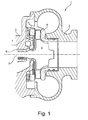
- Fig. 1 Has an inventive exhaust gas turbocharger 1, of which according to the Fig. 1 only the turbine side is shown, a turbine housing 2 and an adjoining bearing housing 3 on.
- the bearing housing 3 is arranged between the turbine housing 2 and a compressor housing, not shown, and serves to support a, a turbine wheel 4 and a not shown compressor wheel supporting shaft 5.
- the turbine wheel 4 is shown in the Fig. 1 arranged within a guide vane cage 6, which may for example surround a variable turbine geometry for influencing a flow cross-section.
- the vane cage 6 is located substantially between the turbine housing 2 and the bearing housing. 3
- a spring device 7, in particular a disc spring device 7, which, independent of temperature, always produces at least approximately the same spring force and thus can provide an approximately constant spring force, preferably at all occurring operating temperatures.
- the disc spring device 7 is according to the Fig. 1 disposed between the bearing housing 3 and the guide vane cage 6.
- the disc spring device 7 is supported on the one hand on the bearing housing 3 and on the other hand indirectly via the guide vane cage 6 on the turbine housing 2.
- the disc spring device 7 in addition to the generation of a constant spring force takes over the task of a heat shield, whereby a particularly functional component can be created.
- the disc spring device 7 may be formed, for example, in the manner of a bimetal. The two metals of a disk spring device 7 designed in this way have different thermal expansion coefficients.
- the disc spring device 7, as this is particularly insistent in the 3 and 4 is shown, composed of at least two individual disc springs 9a and 9b. In this case, the two disc springs 9a and 9b as shown in the Fig.
- the exhaust gas turbocharger 1 for boost pressure control can have an adjustable bypass (wastegate) and / or a variable turbine geometry (VTG / VNT).
- Such exhaust gas turbochargers are usually used in internal combustion engines of motor vehicles.
- the invention is based on the general idea of compensating for the spring force losses of the disc spring device 7 caused by the temperature by means of a suitable pairing of individual or a plurality of disc springs 9a, 9b with different coefficients of thermal expansion.
- a connection of the at least two disc springs 9a and 9b can be done, for example, by a welded, riveted or positive connection, whereby a loose stacking to spring packets with rand wornem positive locking is conceivable.
- the function can be ensured, reliable heat shielding and virtually constant spring properties can be achieved. If the exhaust-gas turbocharger 1 is designed, for example, as a wastegate ATL, the shielding function under unfavorable temperature load and, on the other hand, sufficient spring force at all operating points which in particular reliably prevent the heat shield from rotating during operation, are the focus of consideration.
Landscapes
- Engineering & Computer Science (AREA)
- General Engineering & Computer Science (AREA)
- Mechanical Engineering (AREA)
- Chemical & Material Sciences (AREA)
- Chemical Kinetics & Catalysis (AREA)
- General Chemical & Material Sciences (AREA)
- Combustion & Propulsion (AREA)
- Supercharger (AREA)
Description
- Die vorliegende Erfindung betrifft einen Abgasturbolader für ein Kraftfahrzeug gemäß dem Oberbegriff des Anspruchs 1. Die Erfindung betrifft außerdem einen, mit einem derartigen Abgasturbolader ausgestatteten Verbrennungsmotor sowie ein, mit einem derartigen Verbrennungsmotor ausgestattetes Kraftfahrzeug.
- Aus der
DE 20 2005 009 491 U1 ist ein gattungsgemäßer Abgasturbolader bekannt, der in einem Turbinengehäuse zusätzlich eine Kartusche für eine variable Turbinengeometrie aufweist. Eine Welle des Abgasturboladers ist dabei in einem Lagergehäuse gelagert, das sich zwischen dem Turbinengehäuse und einem Verdichtergehäuse befindet. Zwischen der Kartusche und dem Lagergehäuse ist dabei eine Scheibenanordnung vorgesehen, die aus zumindest zwei Materiallagen mit einem dazwischenliegenden Luftspalt aufgebaut ist. Eine der Materiallagen ist dabei als konische Scheibe ausgebildet, während die andere Materiallage mit einem Knick versehen ist. Hierdurch soll sowohl die Funktion der Vorspannkrafterzeugung als auch eine Verbesserung einer Abschirmfunktion durch Erhöhung des Wärmewiderstandes geschaffen werden. - Aus der
EP 1 905 653 A1 ist ein Hitzeschild zum Abschirmen eines Gegenstandes gegen Hitze und/oder Schall, insbesondere zur Abschirmung eines Katalysators, mit einer Ausnehmung bekannt, die durch den Hitzeschild mit Innen- und Oberfläche hindurchgeht. Die Ausnehmung kann dabei durch einen Verschluss zumindest bereichsweise in Abhängigkeit der Temperatur verschlossen werden, wobei sich der Verschluss in Abhängigkeit der Temperatur selbsttätig öffnet und schließt. Hierdurch soll einerseits ein schnelles Erwärmen des Katalysators auf dessen Betriebstemperatur erreicht und andererseits ein Überhitzen desselben vermieden werden. - Weitere Abgasturbolader sind beispielsweise aus der
US 2007/0134106 A1 , aus derWO 2006/046892 A1 sowie aus derUS 3,692,436 bekannt. - Generell unterliegen üblicherweise sämtliche Bauteile eines Abgasturboladers während dessen Betrieb starken Temperaturschwankungen und bedingt durch die Verwendung unterschiedlicher Werkstoffe sowie unterschiedlicher Geometrien, unterschiedlich starken Ausdehnungen bzw. Dehnverhalten. Dabei müssen insbesondere Federeinrichtungen und Verbindungsmittel im heißgasbelasteten Bereich eines Abgasturboladers derart ausgebildet sein, dass sie auch unter den ungünstigsten anzutreffenden thermischen Bedingungen ihre Aufgabe zuverlässig erfüllen. Dies bedeutet bei Federeinrichtungen und Verbindungsmittel üblicherweise, dass diese hinsichtlich ihrer Abmessungen so dimensioniert werden müssen, dass sie ihre Feder-Nerbindungsaufgabe auch bei den höchsten zu erwartenden Temperaturen noch sicher bewältigen können, was üblicherweise zu einer sehr stark dimensionierten Auslegung der Verbindungsmittel bzw. entsprechender Fehlereinrichtungen führt.
- Die vorliegende Erfindung beschäftigt sich mit dem Problem, für einen Abgasturbolader der gattungsgemäßen Art, eine verbesserte Ausführungsform anzugeben, die sich insbesondere durch eine bedarfsgerechte Dimensionierung von Federeinrichtungen im Hinblick auf eventuell auftretende Temperaturbelastungen auszeichnet.
- Dieses Problem wird erfindungsgemäß durch die Gegenstände der unabhängigen Ansprüche gelöst. Vorteilhaften Ausführungsformen sind Gegenstand der abhängigen Ansprüche.
- Die Erfindung beruht auf dem allgemeinen Gedanken, in einem Abgasturbolader eingesetzte Federeinrichtungen zur axialen Verspannung von Bauteilen derart auszubilden, dass diese temperaturunabhängig eine stets zumindest annähernd gleiche Federkraft erzeugen - mit anderen Worten ausgedrückt - dass die eingesetzten Federeinrichtungen die von ihnen erwartete Federkraft bei jeder zu erwartenden Temperatur bereitstellen können. Eine derartige Federeinrichtung kann beispielsweise eine Tellerfedereinrichtung sein, die zwischen einem Lagergehäuse und einem Turbinengehäuse des Abgasturboladers angeordnet ist und beide gegeneinander verspannt. Denkbar ist aber auch eine Federeinrichtung, insbesondere wieder eine Tellerfedereinrichtung, welche im Bereich einer Lageranordnung einer, ein Turbinenrad und ein Verdichterrad tragenden Welle, im Lagergehäuse angeordnet ist und dort beispielsweise die Aufgabe übernimmt, Lagerschalen axial gegeneinander zu verspannen. Durch eine derartig ausgebildete Federeinrichtung ist es möglich, trotz zeitlich variierender (wechselnder) thermischer Betriebsbedingungen verhältnismäßig gleichbleibende Kräfte zu erzeugen, so dass diese lediglich auf eine tatsächlich zu erzeugende Federkraft ausgelegt sein müssen und nicht wie bisher üblich, auf eine mindest zu erreichende Federkraft bei einer maximalen Arbeitstemperatur, was üblicherweise zu einer deutlich größeren Dimensionierung der Tellerfeder führt. Hierdurch ergeben sich eine Reihe von Vorteilen, wie beispielsweise die Möglichkeit zur Senkung des mittleren Axialkraftniveaus zur Verspannung von Bauteilen im Vergleich zu herkömmlichen Lösungen, die ein deutlich höheres Verspannniveau aufweisen müssen, um eine sichere kraftschlüssige Verbindung von Bauteilen bei wechselnden Temperaturen bzw. Betriebszuständen zu gewährleisten. Die erfindungsgemäß ausgebildeten Federeinrichtungen können somit verringerte Abmessungen (z.B. Durchmesser, Dicke) aufweisen und dadurch auch eine insbesondere kompaktere Bauform ermöglichen. Gegebenenfalls sind hierbei auch Reduzierungsmöglichkeiten der Abmessungen angrenzender bzw. durch die Federeinrichtung zu verspannender Bauteile möglich.
- Zweckmäßig ist die wenigstens eine Federeinrichtung, insbesondere die Tellerfedereinrichtung, zwischen dem Lagergehäuse und dem Turbinengehäuse als Hitzeschild ausgebildet. Ein derartiger Hitzeschild bewirkt eine Abminderung des Wärmeübertrags und soll dadurch insbesondere temperaturempfindliche Bauteile vor einer zu starken Erhitzung schützen. Bei einer als Hitzeschild ausgebildeten Tellerfedereinrichtung sind somit zwei Funktionen durch ein gemeinsames Bauteil zu erfüllen, nämlich einerseits die Erzeugung einer Vorspannkraft und andererseits die Erzeugung eines Hitzeschutzschildes. Bei einer derartigen Ausführungsform kann ein bisher üblicher, zusätzlicher Hitzeschild entfallen, wodurch einerseits die Teilevielfalt und damit die Lager- und Logistikkosten und andererseits ein Montageaufwand gesenkt werden können. Zugleich lassen sich mit der erfindungsgemäßen Tellerfedereinrichtung auch Packagevorteile erzielen, da nunmehr nicht zwei separate Bauteile, nämlich eine Federeinrichtung und einen Hitzeschild, verbaut werden müssen, sondern lediglich ein einziges, beide Funktionen erfüllendes Bauteil.
- Bei einer vorteilhaften Weiterbildung der erfindungsgemäßen Lösung, ist die wenigstens eine Tellerfedereinrichtung in der Art eines Bimetalls ausgebildet. Bimetalle sind üblicherweise Metallelemente aus zwei Schichten unterschiedlicher Materialien, die stoffschlüssig oder formschlüssig miteinander verbunden sind. Charakteristisch ist dabei die Veränderung der Form bei einer Änderung der Temperatur, welche sich üblicherweise als Verbiegung äußert. Ursache hierfür ist die unterschiedliche Wärmeausdehnung der verwendeten Metalle. Als für Bimetalle in Betracht kommende Metalle können beispielsweise Zink und Stahl oder auch Messing und Stahl erwähnt werden. Bimetalle arbeiten äußerst zuverlässig und sind darüber hinaus kostengünstig herzustellen, so dass eine in der Art eines Bimetalls ausgebildete Tellerfedereinrichtung bezüglich ihrer temperaturabhängigen Kraftänderungen so eingestellt werden kann, dass sie über den nahezu vollständig zu erwartenden Temperaturbereich, eine gleich hohe Federkraft erzeugt.
- Weitere wichtige Merkmale und Vorteile der Erfindung ergeben sich aus den Unteransprüchen, aus den Zeichnungen und aus der zugehörigen Figurenbeschreibung anhand der Zeichnungen.
- Es versteht sich, dass die vorstehend genannten und die nachstehend noch zu erläuternden Merkmale nicht nur in der jeweils angegebenen Kombination, sondern auch in anderen Kombinationen oder in Alleinstellung verwendbar sind, ohne den Rahmen der vorliegenden Erfindung zu verlassen.
- Bevorzugte Ausführungsbeispiele der Erfindung sind in den Zeichnungen dargestellt und werden in der nachfolgenden Beschreibung näher erläutert, wobei sich gleiche Bezugszeichen auf gleiche oder ähnliche oder funktional gleiche Bauteile beziehen.
- Dabei zeigen, jeweils schematisch,
- Fig. 1
- eine Schnittdarstellung durch einen erfindungsgemäßen Abgasturbolader,
- Fig. 2
- eine Detaildarstellung im Bereich einer Tellerfedereinrichtung innerhalb des Abgasturboladers,
- Fig. 3
- eine Detailschnittdarstellung durch die Tellerfedereinrichtung mit zwei miteinander verbundenen Einzeltellerfedern,
- Fig. 4
- die einzelnen Tellerfedern der Tellerfedereinrichtung.
- Entsprechend der
Fig. 1 , weist ein erfindungsgemäßer Abgasturbolader 1, von dem gemäß derFig. 1 lediglich die Turbinenseite gezeigt ist, ein Turbinengehäuse 2 sowie ein sich daran anschließendes Lagergehäuse 3 auf. Das Lagergehäuse 3 ist dabei zwischen dem Turbinengehäuse 2 und einem nicht gezeigten Verdichtergehäuse angeordnet und dient zur Lagerung einer, ein Turbinenrad 4 und ein nicht gezeigtes Verdichterrad tragenden Welle 5. Das Turbinenrad 4 ist gemäß der Darstellung derFig. 1 innerhalb eines Leitschaufelkäfigs 6 angeordnet, der beispielsweise eine variable Turbinengeometrie zur Beeinflussung eines Strömungsquerschnittes umgeben kann. Der Leitschaufelkäfig 6 befindet sich dabei im Wesentlichen zwischen dem Turbinengehäuse 2 und dem Lagergehäuse 3. - Erfindungsgemäß ist nun eine Federeinrichtung 7, insbesondere ein Tellerfedereinrichtung 7 vorgesehen, die temperaturunabhängig eine stets zumindest annähernd gleiche Federkraft erzeugt und somit eine bei vorzugsweise sämtlichen auftretenden Betriebstemperaturen annähernd konstante Federkraft bereitstellen kann. Die Tellerfedereinrichtung 7 ist dabei gemäß der
Fig. 1 zwischen dem Lagergehäuse 3 und dem Leitschaufelkäfig 6 angeordnet. Somit stützt sich die Tellerfedereinrichtung 7 einerseits an dem Lagergehäuse 3 und andererseits indirekt über den Leitschaufelkäfig 6 am Turbinengehäuse 2 ab. - Bisher war es üblich, derartige Tellerfedereinrichtungen so zu dimensionieren, dass sie auch bei maximal zu erwartenden Temperaturbelastung eine Mindestfederkraft erzeugen können, was üblicherweise zu einer für den Normalfall Überdimensionierung der Tellerfedereinrichtung führte. Mit der erfindungsgemäßen Tellerfedereinrichtung 7, mit welcher nunmehr unabhängig von der Temperatur eine stets zumindest annähernd gleiche und definierte Federkraft erzeugt werden kann, ist es möglich, die Tellerfedereinrichtung 7 optimal auf die erforderliche Federkraft auszurichten und dadurch insbesondere schwächer auszulegen, wodurch sich auch Packagevorteile bieten. Mit der erfindungsgemäßen Tellerfedereinrichtung 7 ergibt sich somit die Möglichkeit zur Senkung des mittleren Axialkraftniveaus zur Verspannung von Bauteilen innerhalb des Abgasturboladers 1 im Vergleich zu herkömmlichen Lösungen, welche ein deutlich höheres Kraftniveau aufweisen müssen, um eine sichere kraftschlüssige Verbindung der Bauteile bei wechselnden Temperaturen bzw. Betriebszuständen gewährleisten zu können. Selbstverständlich soll dabei das gemäß der
Fig. 1 gezeigte Einsatzgebiet der erfindungsgemäßen Tellerfedereinrichtung 7 rein exemplarisch verstanden werden, so dass diese beispielsweise auch im Bereich einer Lageranordnung 8 eingesetzt werden kann, um beispielsweise zwei in Axialrichtung gegeneinander zu verspannende Lagerschalen zu verspannen. - Denkbar ist hierbei auch, dass die Tellerfedereinrichtung 7 neben der Erzeugung einer konstanten Federkraft die Aufgabe eines Hitzeschildes übernimmt, wodurch ein besonders funktionales Bauelement geschaffen werden kann. Um die Anforderungen der temperaturunabhängigen Krafterzeugung erfüllen zu können, kann die Tellerfedereinrichtung 7 beispielsweise in der Art eines Bimetalls ausgebildet sein. Die beiden Metalle einer derart ausgebildeten Tellerfedereinrichtung 7 weisen dabei unterschiedliche Wärmeausdehnungskoeffizienten auf. Denkbar ist auch, dass die Tellerfedereinrichtung 7, wie dies besonders eindringlich in den
Fig. 3 und 4 gezeigt ist, aus zumindest zwei einzelnen Tellerfedern 9a und 9b zusammengesetzt ist. Dabei weisen die beiden Tellerfedern 9a und 9b gemäß den Darstellungen in denFig. 1 bis 4 eine gleichgroße Radialausstreckung auf, wobei auch denkbar ist, dass die wenigstens zwei Tellerfedern 9a und 9b eine unterschiedliche Radialerstreckung aufweisen. Selbstverständlich können dabei je Abgasturbolader 1 auch mehrere derartige, an die jeweiligen Anforderungen angepasste Tellerfedereinrichtungen 7, zum Einsatz gelangen. Insbesondere kann der Abgasturbolader 1 zur Ladedruckregelung einen regelbaren Bypass (Wastegate) und/oder eine variable Turbinengeometrie (VTG/VNT) aufweisen. Eingesetzt werden derartige Abgasturbolader üblicherweise in Verbrennungsmotoren von Kraftfahrzeugen. - Generell beruht die Erfindung auf dem allgemeinen Gedanken, die aufgrund der Temperatur hervorgerufenen Federkraftverluste der Tellerfedereinrichtung 7 durch eine geeignete Paarung einzelner bzw. mehrerer Tellerfedern 9a, 9b mit unterschiedlichen Wärmeausdehnungskoeffizienten zu kompensieren. Eine Verbindung der zumindest zwei Tellerfedern 9a und 9b kann beispielsweise durch eine Schweiß-, Niet- oder Formschlussverbindung erfolgen, wobei auch eine lose Stapelung zu Federpaketen mit randseitigem Formschluss vorstellbar ist.
- Mit der erfindungsgemäßen (Teller-)federeinrichtung 7 können insbesondere bei einem Abgasturbolader 1 mit einer variablen Turbinengeometrien trotz komplizierter Belastungs- und Temperatursituationen eine Sicherstellung der Funktion, eine zuverlässige Hitzeabschirmung sowie nahezu konstante Federeigenschaften bewirkt werden. Ist der Abgasturbolader 1 beispielsweise als Wastegate-ATL ausgebildet, so stehen einerseits die Abschirmfunktion bei ungünstiger Temperaturbelastung und andererseits eine ausreichende Federkraft in allen Betriebspunkten, die insbesondere ein Verdrehen des Hitzeschildes im Betrieb sicher verhindern, im Vordergrund der Überlegungen.
Claims (7)
- Abgasturbolader (1) für ein Kraftfahrzeug, mit- einem Turbinengehäuse (2), einem Verdichtergehäuse und einem dazwischen angeordneten Lagergehäuse (3),- einer, ein Turbinenrad (4) und ein Verdichterrad tragenden Welle (5), die über eine Lageranordnung (8) im Lagergehäuse (3) gelagert ist,dadurch gekennzeichnet,
dass zumindest eine Tellerfedereinrichtung (7) vorgesehen ist, die aus wenigstens zwei einzelnen Tellerfedern (9a,9b) mit unterschiedlichen Wärmeausdehnungskoeffizienten zusammengesetzt ist, wobei durch die zumindest zwei Tellerfedern (9a,9b) die Tellerfedereinrichtung (7) eine bei sämtlichen auftretenden Betriebstemperaturen annähernd konstante Federkraft bereitstellt. - Abgasturbolader nach Anspruch 1,
dadurch gekennzeichnet,
dass die wenigstens eine Tellerfedereinrichtung (7) zwischen dem Lagergehäuse (3) und dem Turbinengehäuse (2) als Hitzeschild ausgebildet ist. - Abgasturbolader nach Anspruch 1 oder 2,
dadurch gekennzeichnet,
dass die wenigstens eine Tellerfedereinrichtung (7) in der Art eines Bimetalls ausgebildet ist. - Abgasturbolader nach einem der Ansprüche 1 bis 3,
dadurch gekennzeichnet,
dass die wenigstens zwei Tellerfedern (9a, 9b) dieselbe oder eine unterschiedliche Radialerstreckung aufweisen. - Abgasturbolader nach einem der Ansprüche 1 bis 4,
dadurch gekennzeichnet,
dass der Abgasturbolader (1) zur Ladedruckregelung einen regelbaren Bypass (Wastegate) und/oder eine variable Turbinengeometrie (VTG/VNT) aufweist. - Verbrennungsmotor mit einem Abgasturbolader (1) nach einem der Ansprüche 1 bis 5.
- Kraftfahrzeug mit einem Verbrennungsmotor nach Anspruch 6.
Applications Claiming Priority (1)
| Application Number | Priority Date | Filing Date | Title |
|---|---|---|---|
| DE102008032808A DE102008032808A1 (de) | 2008-07-11 | 2008-07-11 | Abgasturbolader für ein Kraftfahrzeug |
Publications (2)
| Publication Number | Publication Date |
|---|---|
| EP2143910A1 EP2143910A1 (de) | 2010-01-13 |
| EP2143910B1 true EP2143910B1 (de) | 2012-03-21 |
Family
ID=41151939
Family Applications (1)
| Application Number | Title | Priority Date | Filing Date |
|---|---|---|---|
| EP09163190A Active EP2143910B1 (de) | 2008-07-11 | 2009-06-19 | Abgasturbolader für ein Kraftfahrzeug |
Country Status (3)
| Country | Link |
|---|---|
| EP (1) | EP2143910B1 (de) |
| AT (1) | ATE550534T1 (de) |
| DE (1) | DE102008032808A1 (de) |
Cited By (1)
| Publication number | Priority date | Publication date | Assignee | Title |
|---|---|---|---|---|
| US10927698B2 (en) | 2019-01-10 | 2021-02-23 | Garrett Transportation I Inc. | Turbocharger with variable-nozzle cartridge, including resilient heat shield assembly to locate the cartridge axially |
Families Citing this family (5)
| Publication number | Priority date | Publication date | Assignee | Title |
|---|---|---|---|---|
| DE102007057309A1 (de) * | 2007-11-28 | 2009-06-10 | Continental Automotive Gmbh | Hitzeschild und Turbolader mit einem Hitzeschild |
| WO2011074039A1 (ja) * | 2009-12-17 | 2011-06-23 | 株式会社Ihi | ターボチャージャ |
| EP3173599B1 (de) * | 2014-11-21 | 2019-10-02 | Mitsubishi Heavy Industries Engine & Turbocharger, Ltd. | Mechanismus für variable düse und turbolader mit variabler verdrängung |
| US20180100429A1 (en) * | 2016-10-12 | 2018-04-12 | Honeywell International Inc. | Variable-nozzle turbocharger with composite heat shroud |
| DE102018210024A1 (de) | 2018-06-20 | 2019-12-24 | BMTS Technology GmbH & Co. KG | Tellerfeder, insbesondere für eine variable Turbinengeometrie eines Abgasturboladers |
Family Cites Families (9)
| Publication number | Priority date | Publication date | Assignee | Title |
|---|---|---|---|---|
| US3692436A (en) | 1971-05-20 | 1972-09-19 | Caterpillar Tractor Co | Thermal compensating support for turbocharger shafts |
| DD268025A1 (de) * | 1987-12-14 | 1989-05-17 | Bannewitz Kompressorenbau | Deckringlose leitgitteranordnung einer radialturbine |
| DE102004038748A1 (de) * | 2004-08-10 | 2006-02-23 | Daimlerchrysler Ag | Abgasturbolader für eine Brennkraftmaschine |
| WO2006046892A1 (en) | 2004-10-28 | 2006-05-04 | Volvo Lastvagnar Ab | Turbo charger unit for an internal combustion engine comprising a heat shield |
| EP1672177B1 (de) * | 2004-12-14 | 2011-11-23 | BorgWarner, Inc. | Turbolader |
| DE202005009491U1 (de) | 2005-06-16 | 2005-08-25 | Borgwarner Inc., Auburn Hills | Turbolader |
| US7517154B2 (en) | 2005-08-11 | 2009-04-14 | Mckeirnan Jr Robert D | Turbocharger shaft bearing system |
| US8784076B2 (en) * | 2006-03-14 | 2014-07-22 | Borgwarner Inc. | Disk spring for a turbocharger |
| DE502006002271D1 (de) | 2006-09-27 | 2009-01-15 | Reinz Dichtungs Gmbh | Hitzeschild |
-
2008
- 2008-07-11 DE DE102008032808A patent/DE102008032808A1/de not_active Withdrawn
-
2009
- 2009-06-19 EP EP09163190A patent/EP2143910B1/de active Active
- 2009-06-19 AT AT09163190T patent/ATE550534T1/de active
Cited By (1)
| Publication number | Priority date | Publication date | Assignee | Title |
|---|---|---|---|---|
| US10927698B2 (en) | 2019-01-10 | 2021-02-23 | Garrett Transportation I Inc. | Turbocharger with variable-nozzle cartridge, including resilient heat shield assembly to locate the cartridge axially |
Also Published As
| Publication number | Publication date |
|---|---|
| EP2143910A1 (de) | 2010-01-13 |
| DE102008032808A1 (de) | 2010-01-14 |
| ATE550534T1 (de) | 2012-04-15 |
Similar Documents
| Publication | Publication Date | Title |
|---|---|---|
| EP2199570B1 (de) | Ladeeinrichtung | |
| DE102009005938A1 (de) | Ladeeinrichtung | |
| EP1891302B1 (de) | Scheibenanordnung für einen turbolader | |
| EP2215340B1 (de) | Hitzeschild und turbolader mit einem hitzeschild | |
| DE102008029080B4 (de) | Abgasturbolader für ein Kraftfahrzeug | |
| EP2143910A1 (de) | Abgasturbolader für ein Kraftfahrzeug | |
| EP2209969B1 (de) | Ladeeinrichtung | |
| WO2009115437A2 (de) | Leitgitteranordnung eines abgasturboladers, abgasturbolader und verfahren zur herstellung einer leitgitteranordnung | |
| DE102009054403A1 (de) | Abgasturbolader | |
| DE102008005658A1 (de) | Ladeeinrichtung | |
| DE102008000852A1 (de) | Abgasturbolader für ein Kraftfahrzeug | |
| DE102008038007A1 (de) | Abgasturbolader | |
| DE102009009130B4 (de) | Turbolader, vorzugsweise mit variabler Turbinengeometrie | |
| DE102008020732A1 (de) | Ladeeinrichtung | |
| WO2009092792A2 (de) | Abgasturbolader | |
| EP1734231A1 (de) | Turbolader und Schaufellagerring hierfür | |
| WO2012146510A2 (de) | Ladeeinrichtung | |
| DE102016122369A1 (de) | Lagerung einer Klappenventilwelle | |
| DE102012001236A1 (de) | Leiteinrichtung für eine Turbine eines Abgasturboladers | |
| DE102008000849A1 (de) | Abgasturbolader für ein Kraftfahrzeug | |
| DE102013001978A1 (de) | Ventileinheit für ein Wastegatesystem und Abgasturbolader | |
| DE102009009129B4 (de) | Turbolader mit variabler Turbinengeometrie | |
| DE102008039508A1 (de) | Ladeeinrichtung | |
| DE102011004345A1 (de) | Abgasturbolader für eine Brennkraftmaschine | |
| DE102008000724B4 (de) | Abgasturbolader mit verstellbarer Turbinengeometrie |
Legal Events
| Date | Code | Title | Description |
|---|---|---|---|
| PUAI | Public reference made under article 153(3) epc to a published international application that has entered the european phase |
Free format text: ORIGINAL CODE: 0009012 |
|
| AK | Designated contracting states |
Kind code of ref document: A1 Designated state(s): AT BE BG CH CY CZ DE DK EE ES FI FR GB GR HR HU IE IS IT LI LT LU LV MC MK MT NL NO PL PT RO SE SI SK TR |
|
| 17P | Request for examination filed |
Effective date: 20100323 |
|
| 17Q | First examination report despatched |
Effective date: 20110202 |
|
| GRAP | Despatch of communication of intention to grant a patent |
Free format text: ORIGINAL CODE: EPIDOSNIGR1 |
|
| GRAS | Grant fee paid |
Free format text: ORIGINAL CODE: EPIDOSNIGR3 |
|
| GRAA | (expected) grant |
Free format text: ORIGINAL CODE: 0009210 |
|
| AK | Designated contracting states |
Kind code of ref document: B1 Designated state(s): AT BE BG CH CY CZ DE DK EE ES FI FR GB GR HR HU IE IS IT LI LT LU LV MC MK MT NL NO PL PT RO SE SI SK TR |
|
| REG | Reference to a national code |
Ref country code: GB Ref legal event code: FG4D Free format text: NOT ENGLISH |
|
| REG | Reference to a national code |
Ref country code: CH Ref legal event code: EP |
|
| REG | Reference to a national code |
Ref country code: IE Ref legal event code: FG4D Free format text: LANGUAGE OF EP DOCUMENT: GERMAN |
|
| REG | Reference to a national code |
Ref country code: AT Ref legal event code: REF Ref document number: 550534 Country of ref document: AT Kind code of ref document: T Effective date: 20120415 |
|
| REG | Reference to a national code |
Ref country code: DE Ref legal event code: R096 Ref document number: 502009003075 Country of ref document: DE Effective date: 20120516 |
|
| REG | Reference to a national code |
Ref country code: NL Ref legal event code: VDEP Effective date: 20120321 |
|
| PG25 | Lapsed in a contracting state [announced via postgrant information from national office to epo] |
Ref country code: NO Free format text: LAPSE BECAUSE OF FAILURE TO SUBMIT A TRANSLATION OF THE DESCRIPTION OR TO PAY THE FEE WITHIN THE PRESCRIBED TIME-LIMIT Effective date: 20120621 Ref country code: LT Free format text: LAPSE BECAUSE OF FAILURE TO SUBMIT A TRANSLATION OF THE DESCRIPTION OR TO PAY THE FEE WITHIN THE PRESCRIBED TIME-LIMIT Effective date: 20120321 Ref country code: HR Free format text: LAPSE BECAUSE OF FAILURE TO SUBMIT A TRANSLATION OF THE DESCRIPTION OR TO PAY THE FEE WITHIN THE PRESCRIBED TIME-LIMIT Effective date: 20120321 |
|
| LTIE | Lt: invalidation of european patent or patent extension |
Effective date: 20120321 |
|
| PG25 | Lapsed in a contracting state [announced via postgrant information from national office to epo] |
Ref country code: LV Free format text: LAPSE BECAUSE OF FAILURE TO SUBMIT A TRANSLATION OF THE DESCRIPTION OR TO PAY THE FEE WITHIN THE PRESCRIBED TIME-LIMIT Effective date: 20120321 Ref country code: FI Free format text: LAPSE BECAUSE OF FAILURE TO SUBMIT A TRANSLATION OF THE DESCRIPTION OR TO PAY THE FEE WITHIN THE PRESCRIBED TIME-LIMIT Effective date: 20120321 Ref country code: GR Free format text: LAPSE BECAUSE OF FAILURE TO SUBMIT A TRANSLATION OF THE DESCRIPTION OR TO PAY THE FEE WITHIN THE PRESCRIBED TIME-LIMIT Effective date: 20120622 |
|
| PG25 | Lapsed in a contracting state [announced via postgrant information from national office to epo] |
Ref country code: CY Free format text: LAPSE BECAUSE OF FAILURE TO SUBMIT A TRANSLATION OF THE DESCRIPTION OR TO PAY THE FEE WITHIN THE PRESCRIBED TIME-LIMIT Effective date: 20120321 |
|
| PG25 | Lapsed in a contracting state [announced via postgrant information from national office to epo] |
Ref country code: PL Free format text: LAPSE BECAUSE OF FAILURE TO SUBMIT A TRANSLATION OF THE DESCRIPTION OR TO PAY THE FEE WITHIN THE PRESCRIBED TIME-LIMIT Effective date: 20120321 Ref country code: CZ Free format text: LAPSE BECAUSE OF FAILURE TO SUBMIT A TRANSLATION OF THE DESCRIPTION OR TO PAY THE FEE WITHIN THE PRESCRIBED TIME-LIMIT Effective date: 20120321 Ref country code: RO Free format text: LAPSE BECAUSE OF FAILURE TO SUBMIT A TRANSLATION OF THE DESCRIPTION OR TO PAY THE FEE WITHIN THE PRESCRIBED TIME-LIMIT Effective date: 20120321 Ref country code: SI Free format text: LAPSE BECAUSE OF FAILURE TO SUBMIT A TRANSLATION OF THE DESCRIPTION OR TO PAY THE FEE WITHIN THE PRESCRIBED TIME-LIMIT Effective date: 20120321 Ref country code: EE Free format text: LAPSE BECAUSE OF FAILURE TO SUBMIT A TRANSLATION OF THE DESCRIPTION OR TO PAY THE FEE WITHIN THE PRESCRIBED TIME-LIMIT Effective date: 20120321 Ref country code: SE Free format text: LAPSE BECAUSE OF FAILURE TO SUBMIT A TRANSLATION OF THE DESCRIPTION OR TO PAY THE FEE WITHIN THE PRESCRIBED TIME-LIMIT Effective date: 20120321 Ref country code: IS Free format text: LAPSE BECAUSE OF FAILURE TO SUBMIT A TRANSLATION OF THE DESCRIPTION OR TO PAY THE FEE WITHIN THE PRESCRIBED TIME-LIMIT Effective date: 20120721 |
|
| PG25 | Lapsed in a contracting state [announced via postgrant information from national office to epo] |
Ref country code: SK Free format text: LAPSE BECAUSE OF FAILURE TO SUBMIT A TRANSLATION OF THE DESCRIPTION OR TO PAY THE FEE WITHIN THE PRESCRIBED TIME-LIMIT Effective date: 20120321 Ref country code: PT Free format text: LAPSE BECAUSE OF FAILURE TO SUBMIT A TRANSLATION OF THE DESCRIPTION OR TO PAY THE FEE WITHIN THE PRESCRIBED TIME-LIMIT Effective date: 20120723 |
|
| BERE | Be: lapsed |
Owner name: BOSCH MAHLE TURBO SYSTEMS G.M.B.H. & CO. KG Effective date: 20120630 |
|
| PLBE | No opposition filed within time limit |
Free format text: ORIGINAL CODE: 0009261 |
|
| STAA | Information on the status of an ep patent application or granted ep patent |
Free format text: STATUS: NO OPPOSITION FILED WITHIN TIME LIMIT |
|
| PG25 | Lapsed in a contracting state [announced via postgrant information from national office to epo] |
Ref country code: DK Free format text: LAPSE BECAUSE OF FAILURE TO SUBMIT A TRANSLATION OF THE DESCRIPTION OR TO PAY THE FEE WITHIN THE PRESCRIBED TIME-LIMIT Effective date: 20120321 Ref country code: NL Free format text: LAPSE BECAUSE OF FAILURE TO SUBMIT A TRANSLATION OF THE DESCRIPTION OR TO PAY THE FEE WITHIN THE PRESCRIBED TIME-LIMIT Effective date: 20120321 Ref country code: MC Free format text: LAPSE BECAUSE OF NON-PAYMENT OF DUE FEES Effective date: 20120630 |
|
| 26N | No opposition filed |
Effective date: 20130102 |
|
| PG25 | Lapsed in a contracting state [announced via postgrant information from national office to epo] |
Ref country code: IT Free format text: LAPSE BECAUSE OF FAILURE TO SUBMIT A TRANSLATION OF THE DESCRIPTION OR TO PAY THE FEE WITHIN THE PRESCRIBED TIME-LIMIT Effective date: 20120321 Ref country code: MK Free format text: LAPSE BECAUSE OF FAILURE TO SUBMIT A TRANSLATION OF THE DESCRIPTION OR TO PAY THE FEE WITHIN THE PRESCRIBED TIME-LIMIT Effective date: 20120321 |
|
| REG | Reference to a national code |
Ref country code: IE Ref legal event code: MM4A |
|
| REG | Reference to a national code |
Ref country code: DE Ref legal event code: R097 Ref document number: 502009003075 Country of ref document: DE Effective date: 20130102 |
|
| PG25 | Lapsed in a contracting state [announced via postgrant information from national office to epo] |
Ref country code: ES Free format text: LAPSE BECAUSE OF FAILURE TO SUBMIT A TRANSLATION OF THE DESCRIPTION OR TO PAY THE FEE WITHIN THE PRESCRIBED TIME-LIMIT Effective date: 20120702 Ref country code: IE Free format text: LAPSE BECAUSE OF NON-PAYMENT OF DUE FEES Effective date: 20120619 Ref country code: BE Free format text: LAPSE BECAUSE OF NON-PAYMENT OF DUE FEES Effective date: 20120630 |
|
| PG25 | Lapsed in a contracting state [announced via postgrant information from national office to epo] |
Ref country code: MT Free format text: LAPSE BECAUSE OF FAILURE TO SUBMIT A TRANSLATION OF THE DESCRIPTION OR TO PAY THE FEE WITHIN THE PRESCRIBED TIME-LIMIT Effective date: 20120321 Ref country code: BG Free format text: LAPSE BECAUSE OF FAILURE TO SUBMIT A TRANSLATION OF THE DESCRIPTION OR TO PAY THE FEE WITHIN THE PRESCRIBED TIME-LIMIT Effective date: 20120621 |
|
| REG | Reference to a national code |
Ref country code: CH Ref legal event code: PL |
|
| PG25 | Lapsed in a contracting state [announced via postgrant information from national office to epo] |
Ref country code: TR Free format text: LAPSE BECAUSE OF FAILURE TO SUBMIT A TRANSLATION OF THE DESCRIPTION OR TO PAY THE FEE WITHIN THE PRESCRIBED TIME-LIMIT Effective date: 20120321 Ref country code: CH Free format text: LAPSE BECAUSE OF NON-PAYMENT OF DUE FEES Effective date: 20130630 Ref country code: LI Free format text: LAPSE BECAUSE OF NON-PAYMENT OF DUE FEES Effective date: 20130630 |
|
| PG25 | Lapsed in a contracting state [announced via postgrant information from national office to epo] |
Ref country code: LU Free format text: LAPSE BECAUSE OF NON-PAYMENT OF DUE FEES Effective date: 20120619 |
|
| PG25 | Lapsed in a contracting state [announced via postgrant information from national office to epo] |
Ref country code: HU Free format text: LAPSE BECAUSE OF FAILURE TO SUBMIT A TRANSLATION OF THE DESCRIPTION OR TO PAY THE FEE WITHIN THE PRESCRIBED TIME-LIMIT Effective date: 20090619 |
|
| REG | Reference to a national code |
Ref country code: AT Ref legal event code: MM01 Ref document number: 550534 Country of ref document: AT Kind code of ref document: T Effective date: 20140619 |
|
| PG25 | Lapsed in a contracting state [announced via postgrant information from national office to epo] |
Ref country code: AT Free format text: LAPSE BECAUSE OF NON-PAYMENT OF DUE FEES Effective date: 20140619 |
|
| REG | Reference to a national code |
Ref country code: FR Ref legal event code: PLFP Year of fee payment: 8 |
|
| REG | Reference to a national code |
Ref country code: FR Ref legal event code: PLFP Year of fee payment: 9 |
|
| REG | Reference to a national code |
Ref country code: DE Ref legal event code: R082 Ref document number: 502009003075 Country of ref document: DE Representative=s name: BRP RENAUD UND PARTNER MBB RECHTSANWAELTE PATE, DE Ref country code: DE Ref legal event code: R081 Ref document number: 502009003075 Country of ref document: DE Owner name: BMTS TECHNOLOGY GMBH & CO. KG, DE Free format text: FORMER OWNER: BOSCH MAHLE TURBO SYSTEMS GMBH & CO. KG, 70376 STUTTGART, DE |
|
| REG | Reference to a national code |
Ref country code: FR Ref legal event code: PLFP Year of fee payment: 10 |
|
| REG | Reference to a national code |
Ref country code: DE Ref legal event code: R082 Ref document number: 502009003075 Country of ref document: DE |
|
| PGFP | Annual fee paid to national office [announced via postgrant information from national office to epo] |
Ref country code: DE Payment date: 20250618 Year of fee payment: 17 |
|
| PGFP | Annual fee paid to national office [announced via postgrant information from national office to epo] |
Ref country code: GB Payment date: 20250618 Year of fee payment: 17 |
|
| PGFP | Annual fee paid to national office [announced via postgrant information from national office to epo] |
Ref country code: FR Payment date: 20250624 Year of fee payment: 17 |