EP2143582A2 - Wind-, Sicht- oder Lichtschutzelement - Google Patents
Wind-, Sicht- oder Lichtschutzelement Download PDFInfo
- Publication number
- EP2143582A2 EP2143582A2 EP09164774A EP09164774A EP2143582A2 EP 2143582 A2 EP2143582 A2 EP 2143582A2 EP 09164774 A EP09164774 A EP 09164774A EP 09164774 A EP09164774 A EP 09164774A EP 2143582 A2 EP2143582 A2 EP 2143582A2
- Authority
- EP
- European Patent Office
- Prior art keywords
- flat material
- frame
- transformation temperature
- clamping surface
- heating
- Prior art date
- Legal status (The legal status is an assumption and is not a legal conclusion. Google has not performed a legal analysis and makes no representation as to the accuracy of the status listed.)
- Granted
Links
- 239000000463 material Substances 0.000 claims abstract description 93
- 230000009466 transformation Effects 0.000 claims abstract description 34
- 238000010438 heat treatment Methods 0.000 claims abstract description 31
- 238000000034 method Methods 0.000 claims abstract description 11
- 238000004519 manufacturing process Methods 0.000 claims abstract description 8
- 239000000835 fiber Substances 0.000 claims description 41
- 230000001681 protective effect Effects 0.000 claims description 10
- 238000006243 chemical reaction Methods 0.000 claims description 9
- 230000000007 visual effect Effects 0.000 claims description 8
- 239000004744 fabric Substances 0.000 claims description 6
- 230000005855 radiation Effects 0.000 claims description 6
- 230000000717 retained effect Effects 0.000 abstract 1
- 239000000243 solution Substances 0.000 description 8
- 238000002347 injection Methods 0.000 description 7
- 239000007924 injection Substances 0.000 description 7
- 230000035699 permeability Effects 0.000 description 7
- 238000010792 warming Methods 0.000 description 5
- 230000008901 benefit Effects 0.000 description 4
- 230000015572 biosynthetic process Effects 0.000 description 4
- 230000008859 change Effects 0.000 description 3
- 238000001816 cooling Methods 0.000 description 3
- 238000007665 sagging Methods 0.000 description 3
- 239000012530 fluid Substances 0.000 description 2
- 239000002184 metal Substances 0.000 description 2
- 230000008569 process Effects 0.000 description 2
- 230000037072 sun protection Effects 0.000 description 2
- 230000037303 wrinkles Effects 0.000 description 2
- 230000002411 adverse Effects 0.000 description 1
- 230000008602 contraction Effects 0.000 description 1
- 239000007788 liquid Substances 0.000 description 1
- 238000003825 pressing Methods 0.000 description 1
Images




Classifications
-
- B—PERFORMING OPERATIONS; TRANSPORTING
- B60—VEHICLES IN GENERAL
- B60J—WINDOWS, WINDSCREENS, NON-FIXED ROOFS, DOORS, OR SIMILAR DEVICES FOR VEHICLES; REMOVABLE EXTERNAL PROTECTIVE COVERINGS SPECIALLY ADAPTED FOR VEHICLES
- B60J7/00—Non-fixed roofs; Roofs with movable panels, e.g. rotary sunroofs
- B60J7/22—Wind deflectors for open roofs
- B60J7/223—Wind deflectors for open roofs specially adapted for convertible cars
Definitions
- the invention relates to a wind, visual or light protection element comprising a flat material and a receiving the flat material and clamped in a clamping surface holding frame.
- Such a wind, visual or light protection element is known from the prior art, in which in each case the flat material must be fixed in a tensioned in the clamping surface and wrinkle-free state to the frame.
- the invention is therefore based on the object to improve a wind, visual or light protection element of the generic type such that it is as easy as possible to produce, in particular, the flat material should be as easy as possible to fix the frame.
- This object is achieved in a wind, visual or light protection element according to the invention in that the sheet is made of a by placing it at a temperature above a conversion temperature in the clamping surface under stress-setting material.
- the advantage of the solution according to the invention is the fact that with this the mounting of the sheet material on the frame can be done much easier, since after mounting the sheet on the frame the possibility exists, this by heating to the transformation temperature in a live To set state so that the flat material spans automatically in the frame and compensates for drape and sagging of the same in the frame and maintains this condition on subsequent cooling to the onset temperature.
- the flat material is formed from a fiber structure which automatically generates the voltage when heating to the transformation temperature in at least one expansion direction lying in the clamping surface.
- Such a variant provides that the fiber structure has fibers with a fiber profile, which changes when heated to the transformation temperature.
- fibers are provided which have a different structure from a rectilinear extent of the fiber, for example a crimped or folded or looped or meandering structure, which fibers, when heated to the transformation temperature, crimp or fold or emboss their loops or meanders more intensively and thereby be able to put the flat material under tension in the clamping surface.
- a crimped or folded or looped or meandering structure which fibers, when heated to the transformation temperature, crimp or fold or emboss their loops or meanders more intensively and thereby be able to put the flat material under tension in the clamping surface.
- the fiber structure is designed such that it generates a tension in at least two extension directions extending transversely to one another in the clamping surface.
- the sheet of a fibrous structure which changes upon heating to the transformation temperature and thereby generates the stress in the clamping surface
- the flat material is a woven and / or knitted fabric and / or knitted fabric and / or nonwoven and / or scrim of fibers.
- the flat material is produced from a knitted fabric of fibers, since with such a knitted fabric, in particular fibers with a changing fiber structure can be advantageously used.
- the flat material is elastically extensible in at least one expansion direction lying in the clamping surface.
- Such an elastic extensibility is preferably given both before the warming to the transformation temperature and after warming to the transformation temperature, so that in particular the set after warming to the transformation temperature under tension sheet maintains this tension during the lifetime of the protective element.
- the flat material is a pliable flat material, which can be arranged in particular in any desired clamping surfaces.
- the flat material is made of a different material from the material of the frame material, so that the frame can be produced in a known simple manner either of metal or plastic, in particular as an injection molded part, regardless of the flat material and below a connection between the frame and the flat material takes place.
- the flat material is held in a receptacle of the frame by a frictional connection.
- such a frictional connection provides a clamping connection between the flat material and the frame.
- a preferred embodiment provides that the frame has a receptacle in which the flat material is held clamped by a piping.
- a supplementary or alternative embodiment provides that the flat material is held by a positive connection in a receptacle of the frame.
- Such a positive connection can for example be designed so that the frame has form-fitting ends of the flat material engaging positive locking elements, such as projections or pins.
- a further advantageous solution provides that the frame is integrally formed on an edge region of the flat material.
- the frame molded either partially or as a whole to an edge region of the sheet or is welded so that a material connection between the edge region of the sheet and the frame, during the manufacture of the frame, arises, which allows a very simple manufacturing process of the frame, and in particular thereby the protective element according to the invention can be easily produced, as in this Injection of the frame to the edge region of the sheet material, the sheet must not be kept taut, but may protrude loosely into the injection mold, according to the invention then the clamping of the sheet material after production of the frame, so that the strained sheet to the after manufacture of the frame itself changing shape, such as by shrinking changing shape, the same adapts.
- the invention relates to a method for producing a wind, visual or light protection element made of a flat material and a frame holding the flat material tensioned in a clamping surface.
- the method according to the invention is also based on the object mentioned at the outset, namely the simplest possible manufacture of such a protective element.
- the flat material is heated to the conversion temperature after reaching a final shape of the frame, so that there is still the possibility to compensate for changes in shape of the frame, in particular a frame made by plastic injection, in which put under tension of the sheet with.
- the heating of the sheet can be done in a variety of ways.
- a warm medium could be, for example, a liquid, a vapor or a gas.
- the flat material is heated to the conversion temperature by radiation, in particular thermal radiation.
- the flat material is heated to the transformation temperature by heating to this and not to the frame.
- This is understood in particular to mean any process which leads to an immediate heating of the sheet, but not to an immediate heating of the frame, so that, for example, in the case of a warm medium, the medium is directed directly to the sheet and not to the frame and in the same Way the radiation is directed directly to the sheet and not on the frame.
- the frame is screened when heating the sheet to the transformation temperature.
- FIG. 1 and 2 illustrated first embodiment of a windshield element according to the invention for motor vehicles, designed as Windstop adopted for a convertible vehicle whose body 10 in FIG. 1 and 2 1, a wind deflector 12, which projects beyond a belt line 14 of the body 10 of the motor vehicle, and a cover 16, which with respect to a direction of travel 18 a behind the wind deflector 12 lying portion 20 of a arranged approximately at the waist line 14
- Passenger compartment opening 22 covers.
- the portion 20 of the passenger compartment opening 22 is above a rear seat system 24, which has a seat 26 and a rear seat back 28.
- the portion 20 of the passenger compartment opening 22 connects directly to the rear seat back 28 and extends in the direction of travel 18 to the wind deflector 12 also connected to the body side walls 30 in the belt line 14th
- the wind deflector 12 is seated so that this substantially immediately behind drawing in FIG. 2 Headrests 32, not shown, are arranged by front seats 34 of the motor vehicle.
- the cover 16 is preferably hinged to the wind deflector 12, for example pivotable about a folding axis 36, and both together are not shown in detail on drawing fuser devices, which are arranged either on the wind deflector 12 or on the cover 16, in the region of the belt line 14 the body 10, for example in the region of the side walls 30, fixed.
- a fixing device for the cover 16 in the area of the rear seat system 24 is provided.
- the airflow 40 raised from a front side 40 and a windshield 42 via a front passenger compartment 44 located behind the windshield 42 tends to flow past the front passenger compartment 44 and wind deflector 12, but after the wind deflector 12 lower in the direction of the body 10.
- both the wind deflector 12 and the cover 16 are partially permeable to air, in such a way that the air permeability of the wind deflector 12 is greater than the air permeability of the cover 16th
- the cover 16 has an air permeability greater than zero to prevent the formation of a negative pressure in the passenger compartment area 44 and the wind deflector 12 has an air permeability which is at least twice the air permeability of the cover 16.
- the wind deflector 12 is formed from a wind blocker frame 50 which comprises two frame parts 52 and 54 which are pivotable relative to each other about a pivot axis 56, which represents, for example, a center axis of the wind blocker frame 50 and thus from an unfolded functional position in which the wind blocker frame 50 extends with a maximum extent transverse to the direction of travel 18 in the direction of its frame surface, can be brought into a folding position in which the frame parts 52, 54 are approximately on top of each other.
- the flat material F extends in a clamping surface AF in the expansion directions A1 and A2 and is permeable to air, but designed so that it - as already described - blocks a rapid flow of air.
- the frame parts 52, 54 are formed so that they are connected to each other via hinges 62, 64 and each C-shaped extend on both sides of the pivot axis 56, so that in the functional position, the frame opening 58 in total of the C-shaped frame members 52, 54 enclosed and thus in particular in the region of the pivot axis 56 is not divided by struts.
- the cover 16 is likewise formed from two cover parts 72, 74, which are separated from each other in the region of a parting plane 76 in which the pivot axis 56 is located.
- the two cover parts 72 and 74 or only one of them are pivotally pivotable, for example about the folding axis 32, connected to the wind deflector 12 in order to be able to fold the entire Windstop worn can.
- a folding takes place in accordance with DE 195 45 405 to which reference is made in full in this regard, wherein in this type of folding both cover parts 72 and 74 are pivotally connected to the wind deflector 12, in each case with one of the frame parts 52, 54, so that when folding the same one Pivoting about the pivot axis 56 and folding the frame parts 52 and 54 and the cover parts 72 and 74 takes place, in such a way that the frame parts 52, 54 to each other and between the cover parts 72, 74 lie.
- each of the cover members 72 and 74 includes a cover frame 80, 82 which is fixable to the body 10 in the manner described.
- Each cover frame 80, 82 encloses an opening 84, 86 which is closed by a cover frame insert 88, 90 in the form of a flat material F extending in a clamping surface AF.
- a frame tube 90 is provided with a recess 92, in which a piping 94 can be inserted and fixed by pressing.
- the fixing takes place in that an edge region 96 of the sheet material F is pressed with the piping 94 into the recess and is fixed by the piping 94 between this and the recess 92 bounding wall 98 by clamping, so that the sheet F by a Edge 99 of the recess 92 is held in the clamping surface AF.
- a second embodiment of a wind sight or light protection element according to the invention for motor vehicles shown in FIG. 4 , comprises a frame 100 which encloses a frame opening 102, wherein the frame opening 102 is closed by a frame insert 104 in the form of a flat material F.
- the flat material F forming the frame insert 104 extends in the clamping surface AF and is held between two frame parts 110, 112 forming the frame 100 in that the flat material in the clamping surface AF has an edge region 114 beyond the frame opening 102 between the frame parts 110 and 112 and is thus held between the frame parts 110 and 112.
- one of the frame parts 110 or 112 is provided with a positive-locking element 116 in the form of a projection, which engages in a recess 118 in the edge region 114.
- the frame parts 110 'and 112' are molded onto the edge portions 114, that is, formed in the course of an injection process, so that a cohesive connection between the at least one of the frame parts 110 or 112 and the edge region 114 is present, for which purpose the edge region 114 is inserted into an injection mold intended for producing the frame parts 110 'and 112'.
- the flat material F is now designed so that this example, as in FIG. 7 4, a knitted fabric G is formed, which shows knitted areas W in plan view as well as openings O lying between the knitted areas W, which are respectively enclosed by the knitted areas W.
- the ratio of the knitted areas W to the openings O can thereby adjust the air permeability of the sheet and thus produce a relative air permeability of different flat material F for the wind deflector 12 or the cover 16.
- individual knitted fibers FA are thus knitted with a fibrous structure FS such that, as in FIG. 8 Although the individual fibers FA have a shape deviating from a straight course, they are stretched overall.
- the fibers FA are in an in FIG. 9 represented fiber structure FS 'pass, in which the flat material F can be stretched in both expansion directions A1 and A2 of the respective clamping surface AF by a change of the fiber structure FS in the fiber structure FS' in the respective clamping surface AF, wherein, for example, by heating above the conversion temperature, the fibers take the fiber structure FS ', which is a greater deviation from a straight course of the fibers FA
- the fiber structure FS ' is shortened in one or both of the extension directions A1 or A2, whereby the fibers FA themselves are not shortened but only their deviation from a straight or elongated course is enhanced, thereby To generate stress in the extension directions A1 and A2 of the expansion surface AF.
- the fibers FA 'of a material consisting of prestressed fibers FA', which contract when heated above the transformation temperature in its longitudinal direction L and thereby also cause the sheet F in the extension directions A1 and A2 when heated over the conversion temperature contracts.
- the inventive solution is both in metal frames that do not change their shape, as well as plastic frames that change their shape, for example, after the plastic injection due to the shrinkage, in particular reduce the respective frame opening, can be used as such thermal changes of the respective Frame and thus a more or less strong sagging of the sheet material F compensate for the fact that then the sheet F is heated above the transformation temperature and thus passes into a state of stress, which causes sufficiently large shrinkage of the sheet that the strained sheet then the present Shape and extent of the respective frame adapts.
- the sheet F is heated by either a hot fluid stream 120 or by radiation, with both the hot fluid and the radiation being shielded by shields 122 from the respective frame 50, 80, 82, or 100
- the sheet F is heated by either a hot fluid stream 120 or by radiation, with both the hot fluid and the radiation being shielded by shields 122 from the respective frame 50, 80, 82, or 100
- the flat material F is preferably a flat material F that behaves elastically both before heating above the transformation temperature and after heating above the transformation temperature and subsequent cooling, so that it is able to withstand the stress which occurs on heating above the transformation temperature also in the following Cooling to maintain the use temperature for a long time, so that a single heating of the sheet F over the transformation temperature during the lifetime of the respective wind, light or sun protection is sufficient to its voltage in the clamping surface AF during the lifetime of the product receive.
Landscapes
- Engineering & Computer Science (AREA)
- Mechanical Engineering (AREA)
- Lining Or Joining Of Plastics Or The Like (AREA)
- Air-Conditioning For Vehicles (AREA)
- Body Structure For Vehicles (AREA)
- Harvester Elements (AREA)
Abstract
Description
- Die Erfindung betrifft ein Wind-, Sicht- oder Lichtschutzelement umfassend ein Flachmaterial und einen das Flachmaterial aufnehmenden sowie in einer Aufspannfläche gespannt haltenden Rahmen.
- Ein derartiges Wind-, Sicht- oder Lichtschutzelement ist aus dem Stand der Technik bekannt, wobei bei diesem jeweils das Flachmaterial in einem in der Aufspannfläche gespannten und faltenfreien Zustand an dem Rahmen fixiert werden muss.
- Dies erfordert es, dass das Flachmaterial bei der Montage an dem Rahmen oder bei der Verbindung mit dem Rahmen durch geeignete Vorrichtungen gespannt gehalten werden muss, wodurch die Montage des Flachmaterials an dem Rahmen aufwendig ist.
- Der Erfindung liegt daher die Aufgabe zugrunde, ein Wind-, Sicht- oder Lichtschutzelement der gattungsgemäßen Art derart zu verbessern, dass dieser möglichst einfach herstellbar ist, wobei insbesondere das Flachmaterial möglichst einfach an dem Rahmen fixierbar sein soll.
- Diese Aufgabe wird bei einem Wind-, Sicht- oder Lichtschutzelement erfindungsgemäß dadurch gelöst, dass das Flachmaterial aus einem durch Erwärmen auf eine über einer Einsatztemperatur liegende Wandlungstemperatur sich in der Aufspannfläche unter Spannung setzenden Material ist.
- Der Vorteil der erfindungsgemäßen Lösung ist darin zu sehen, dass mit dieser die Montage des Flachmaterials an dem Rahmen weit einfacher erfolgen kann, da nach einer Montage des Flachmaterials an dem Rahmen die Möglichkeit besteht, dies durch ein Erwärmen auf die Wandlungstemperatur in einen unter Spannung stehenden Zustand zu setzen, so dass sich das Flachmaterial selbstständig in dem Rahmen spannt und Faltenwurf sowie ein Durchhängen desselben in dem Rahmen ausgleicht und bei nachfolgendem Abkühlen auf die Einsetztemperatur diesen Zustand aufrecht erhält.
- Dies führt zu einer signifikanten Vereinfachung der Montage des Flachmaterials an dem Rahmen.
- Besonders günstig ist es dabei, wenn das Flachmaterial aus einer Faserstruktur gebildet ist, welche beim Erwärmen auf die Wandlungstemperatur in mindestens einer in der Aufspannfläche liegenden Ausdehnungsrichtung selbsttätig die Spannung erzeugt.
- Der Vorteil dieser Lösung ist darin zu sehen, dass damit die Faserstruktur selbst bei Aufwärmen auf die Wandlungstemperatur die erforderliche Spannung erzeugt.
- Eine derartige Variante sieht vor, dass die Faserstruktur Fasern mit einem Faserverlauf aufweist, der sich beim Erwärmen auf die Wandlungstemperatur ändert.
- Beispielsweise sind bei einer derartigen Faserstruktur Fasern vorgesehen, die eine von einer geradlinigen Erstreckung der Faser abweichende Struktur, beispielsweise eine gekräuselte oder eine gefaltete oder eine in Schlingen oder Mäandern verlaufende Struktur aufweisen, wobei die Fasern bei einer Erwärmung auf die Wandlungstemperatur ihre Kräuselung oder ihre Faltung oder ihre Schlingen oder Mäander noch verstärkt ausprägen und dadurch in der Lage sind, in der Aufspannfläche das Flachmaterial unter Spannung zu setzen.
- Besonders zweckmäßig ist es, wenn die Faserstruktur so ausgebildet ist, dass diese in mindestens zwei in der Aufspannfläche liegenden und quer zueinander verlaufenden Ausdehnungsrichtungen eine Spannung erzeugt.
- Alternativ oder ergänzend zur Ausbildung des Flachmaterials aus einer Faserstruktur, die sich beim Erwärmen auf die Wandlungstemperatur ändert und dadurch die Spannung in der Aufspannfläche erzeugt, ist es ebenfalls denkbar, das Flachmaterial aus Fasern auszubilden, welche aus einem vorgedehnten Material sind, das sich beim Erwärmen auf die Wandlungstemperatur kontrahiert, das heißt, dass sich in diesem Fall die tatsächliche Länge der Faser verkürzt, um die Spannung in der Aufspannfläche zu erzeugen.
- Hinsichtlich der Ausbildung des Flachmaterials wurden bislang keine näheren Angaben gemacht. So sieht eine vorteilhafte Lösung vor, dass das Flachmaterial ein Gewebe und/oder Gestricke und/oder Gewirke und/oder Vlies und/oder Gelege aus Fasern ist.
- Als besonders vorteilhaft hat es sich erwiesen, wenn das Flachmaterial aus einem Gewirke aus Fasern hergestellt ist, da bei einem derartigen Gewirke insbesondere Fasern mit einer sich ändernden Faserstruktur vorteilhaft einsetzbar sind.
- Um ferner das Flachmaterial dauerhaft in dem Rahmen gespannt halten zu können, ist vorzugsweise vorgesehen, dass das Flachmaterial in mindestens einer in der Aufspannfläche liegenden Ausdehnungsrichtung elastisch dehnbar ist.
- Eine derartige elastische Dehnbarkeit ist vorzugsweise sowohl vor dem Aufwärmen auf die Wandlungstemperatur als auch nach dem Aufwärmen auf die Wandlungstemperatur gegeben, so dass insbesondere das nach dem Aufwärmen auf die Wandlungstemperatur unter Spannung gesetzte Flachmaterial diese Spannung während der Lebenszeit des Schutzelements aufrecht erhält.
- Hinsichtlich der Art des Flachmaterials wurden im Zusammenhang mit der bisherigen Erläuterung der einzelnen Ausführungsbeispiele keine näheren Angaben gemacht. So sieht eine vorteilhafte Ausführungsform vor, dass das Flachmaterial ein biegeschlaffes Flachmaterial ist, welches sich insbesondere in beliebig ausgebildeten Aufspannflächen anordnen lässt.
- Vorzugsweise ist ferner vorgesehen, dass das Flachmaterial aus einem sich von dem Material des Rahmens unterscheidenden Material hergestellt ist, so dass sich der Rahmen in bekannter einfacher Art und Weise entweder aus Metall oder aus Kunststoff, insbesondere als Spritzgussteil, unabhängig vom Flachmaterial herstellen lässt und nachfolgend eine Verbindung zwischen dem Rahmen und dem Flachmaterial erfolgt.
- Hinsichtlich der Befestigung des Flachmaterials an dem Rahmen wurden bislang keine näheren Angaben gemacht.
- So ist vorzugsweise vorgesehen, dass das Flachmaterial in einer Aufnahme des Rahmens durch eine kraftschlüssige Verbindung gehalten ist.
- Beispielsweise sieht eine derartige kraftschlüssige Verbindung eine Klemmverbindung zwischen dem Flachmaterial und dem Rahmen vor.
- Eine bevorzugte Ausführung sieht dabei vor, dass der Rahmen eine Aufnahme aufweist, in welcher das Flachmaterial durch einen Keder geklemmt gehalten ist.
- Eine ergänzende oder alternative Ausführungsform sieht vor, dass das Flachmaterial durch eine formschlüssige Verbindung in einer Aufnahme des Rahmens gehalten ist.
- Eine derartige formschlüssige Verbindung kann beispielsweise so ausgeführt sein, dass der Rahmen an Formschlussenden des Flachmaterials angreifende Formschlusselemente, wie beispielsweise Vorsprünge oder Zapfen aufweist.
- Eine weitere vorteilhafte Lösung sieht vor, dass der Rahmen an einen Randbereich des Flachmaterials angeformt ist.
- In diesem Fall ist eine besonders einfache Art der Herstellung des Rahmens möglich, nämlich dadurch, dass der Rahmen entweder teilweise oder als Ganzes an einen Randbereich des Flachmaterials angespritzt oder angeschweißt ist, so dass eine stoffschlüssige Verbindung zwischen dem Randbereich des Flachmaterials und dem Rahmen, und zwar während der Herstellung des Rahmens, entsteht, die einen sehr einfachen Herstellungsprozess des Rahmens erlaubt, und sich insbesondere dadurch das erfindungsgemäße Schutzelement einfach herstellen lässt, da bei diesem Anspritzen des Rahmens an den Randbereich des Flachmaterials das Flachmaterial nicht gespannt gehalten werden muss, sondern lose in die Spritzgussform hineinragen kann, wobei erfindungsgemäß dann das Spannen des Flachmaterials nach Herstellung des Rahmens erfolgt, so dass sich das gespannte Flachmaterial an die nach Herstellung des Rahmens sich verändernde Form, beispielsweise durch Schrumpfen verändernde Form, desselben anpasst.
- Darüber hinaus betrifft die Erfindung ein Verfahren zum Herstellen eines Wind-, Sicht- oder Lichtschutzelements aus einem Flachmaterial und einem das Flachmaterial in einer Aufspannfläche gespannt haltenden Rahmen.
- Auch dem erfindungsgemäßen Verfahren liegt die eingangs genannte Aufgabe, nämlich eine möglichst einfache Herstellung eines derartigen Schutzelements, zugrunde.
- Diese Aufgabe wird bei einem derartigen Verfahren erfindungsgemäß dadurch gelöst, dass das Flachmaterial spannungsfrei an dem Rahmen fixiert wird und durch Erwärmen auf eine über einer Einsatztemperatur liegende Wandlungstemperatur in dem Rahmen unter Spannung gesetzt wird.
- Der Vorteil dieses erfindungsgemäßen Verfahrens ist derselbe, wie eingangs beschrieben, nämlich eine sehr einfache Möglichkeit zur Herstellung eines derartigen erfindungsgemäßen Schutzelementes.
- Insbesondere ist dabei vorgesehen, dass das Flachmaterial nach Erreichen einer Endform des Rahmens auf die Wandlungstemperatur erwärmt wird, so dass damit noch die Möglichkeit besteht, Formveränderungen des Rahmens, insbesondere eines durch Kunststoffspritzen hergestellten Rahmens, bei dem unter Spannung setzen des Flachmaterials mit auszugleichen.
- Die Erwärmung des Flachmaterials kann auf unterschiedlichste Art und Weise erfolgen.
- Eine vorteilhafte Lösung sieht vor, dass das Flachmaterial durch ein warmes Medium auf die Wandlungstemperatur erwärmt. Ein derartiges warmes Medium könnte beispielsweise eine Flüssigkeit, ein Dampf oder ein Gas sein.
- Beispielsweise ist es denkbar, beispielsweise einen Dampf einzusetzen.
- Alternativ dazu ist vorzugsweise vorgesehen, dass das Flachmaterial durch Strahlung, insbesondere Wärmestrahlung auf die Wandlungstemperatur erwärmt wird.
- Um thermische Ausdehnungen des Rahmens beim Erwärmen des Flachmaterials auf die Wandlungstemperatur weitgehend zu vermeiden ist vorzugsweise vorgesehen, dass das Flachmaterial durch eine auf dieses und nicht auf den Rahmen gerichtete Erwärmung auf die Wandlungstemperatur erwärmt wird.
- Hierunter ist insbesondere jeder Prozess zu verstehen, der zu einer unmittelbaren Erwärmung des Flachmaterials führt, jedoch nicht zu einer unmittelbaren Erwärmung des Rahmens, so dass beispielsweise im Fall eines warmen Mediums das Medium unmittelbar auf das Flachmaterial und nicht auf den Rahmen gerichtet wird und in gleicher Weise auch die Strahlung hierbei unmittelbar auf das Flachmaterial und nicht auf den Rahmen gerichtet wird.
- Um die Erwärmung des Rahmens möglichst gering zu halten, ist es besonders vorteilhaft, wenn der Rahmen beim Erwärmen des Flachmaterials auf die Wandlungstemperatur abgeschirmt wird.
- Weitere Merkmale und Vorteile der Erfindung sind Gegenstand der nachfolgenden Beschreibung sowie der zeichnerischen Darstellung einiger Ausführungsbeispiele.
- In der Zeichnung zeigen:
- Figur 1
- eine Seitenansicht einer Karosserie eines Kraftfahrzeugs mit einem erfindungsgemäßen Windschutzelement;
- Figur 2
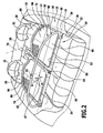
- eine ausschnittsweise perspektivische Darstellung des Windschutzelements gemäß
Figur 1 montiert an der Karosserie des Kraftfahrzeugs, - Figur 3
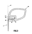
- einen Querschnitt durch einen der Rahmen des ersten Ausführungsbeispiels des erfindungsgemäßen Windschutzelements mit Fixierung eines von dem jeweiligen Rahmen aufgespannten Flachmaterials;
- Figur 4
- eine perspektivische Draufsicht auf ein zweites Ausführungsbeispiels eines erfindungsgemäßen Wind-, Sicht- oder Lichtschutzelements;
- Figur 5
- einen Schnitt längs Linie 5-5 bei dem zweiten Ausführungsbeispiel;
- Figur 6
- einen Schnitt ähnlich
Figur 5 durch ein drittes Ausführungsbeispiel eines erfindungsgemäßen Wind-, Sicht- oder Lichtschutzelements; - Figur 7
- eine ausschnittsweise Darstellung einer Draufsicht auf eine Ausführungsform eines erfindungsgemäßen Flachmaterials;
- Figur 8
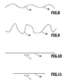
- eine schematische Darstellung einer Faserstruktur im Flachmaterial vor einer Erwärmung auf eine Wandlungstemperatur;
- Figur 9
- eine schematische Darstellung der Faserstruktur nach der Erwärmung auf die Wandlungstemperatur;
- Figur 10
- eine schematische Darstellung einer gedehnten Faser vor einer Erwärmung auf die Wandlungstemperatur;
- Figur 11
- eine schematische Darstellung der gedehnten Faser nach einer Erwärmung auf die Wandlungstemperatur; und
- Figur 12
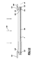
- eine schematische Darstellung einer Erwärmung des erfindungsgemäßen Flachmaterials in dem Rahmen 100'.
- Ein in
Figur 1 und2 dargestelltes erstes Ausführungsbeispiel eines erfindungsgemäßen Windschutzelement für Kraftfahrzeuge, ausgebildet als Windstopeinrichtung für ein Cabrio-Fahrzeug, dessen Karosserie 10 inFigur 1 und2 ausschnittsweise dargestellt ist, umfasst ein Windschott 12, welches über eine Gürtellinie 14 der Karosserie 10 des Kraftfahrzeugs nach oben übersteht, sowie eine Abdeckung 16, welche bezogen auf eine Fahrtrichtung 18 einen hinter dem Windschott 12 liegenden Teilbereich 20 einer ungefähr in Höhe der Gürtellinie 14 angeordneten Fahrgastraumöffnung 22 abdeckt. Beispielsweise liegt der Teilbereich 20 der Fahrgastraumöffnung 22 über einer Rücksitzanlage 24, welche eine Sitzbank 26 sowie eine Rücksitzlehne 28 aufweist. - Vorzugsweise schließt dabei der Teilbereich 20 der Fahrgastraumöffnung 22 unmittelbar an der Rücksitzlehne 28 an und erstreckt sich in der Fahrtrichtung 18 bis zum Windschott 12 ebenfalls unter Anschluss an Karosserieseitenwände 30 im Bereich der Gürtellinie 14.
- Zweckmäßigerweise sitzt dabei das Windschott 12 so, dass dieses im Wesentlichen unmittelbar hinter zeichnerisch in
Figur 2 nicht dargestellten Kopfstützen 32 von Vordersitzen 34 des Kraftfahrzeugs angeordnet ist. - Die Abdeckung 16 ist mit dem Windschott 12 vorzugsweise gelenkig, beispielsweise um eine Klappachse 36 verschwenkbar, verbunden und beide gemeinsam sind über zeichnerisch nicht im einzelnen dargestellte Fixiereinrichtungen, die entweder am Windschott 12 oder an der Abdeckung 16 angeordnet sind, im Bereich der Gürtellinie 14 an der Karosserie 10, beispielsweise im Bereich der Seitenwände 30, fixierbar.
- Zusätzlich ist vorteilhafterweise noch eine Fixiereinrichtung für die Abdeckung 16 im Bereich der Rücksitzanlage 24 vorgesehen.
- Wie in
Figur 1 dargestellt, hat bei einem Cabrio-Fahrzeug die von einer Frontseite 40 und einer Windschutzscheibe 42 über einen vorderen, hinter der Windschutzscheibe 42 liegenden Fahrgastraumbereich 44 angehobene Luftströmung 40 die Tendenz über den vorderen Fahrgastraumbereich 44 und das Windschott 12 hinwegzuströmen, sich jedoch nach dem Windschott 12 in Richtung der Karosserie 10 abzusenken. Dies würde bei einer für die Luftströmung 46 durchlässigen Abdeckung 16 zur Folge haben, dass die Luftströmung 46 die Abdeckung 16 durchsetzen würde, und, wie gestrichelt als Luftströmung 48 dargestellt, von der Rücksitzanlage 24 in Richtung des Fahrgastraumbereichs 44 strömen und dann aus diesem wieder über das Windschott 12 hinwegströmen würde, so dass die bereits erwähnten Zugerscheinungen im Fahrgastraumbereich 44 auftreten würden. - Andererseits hätte ein komplett luftundurchlässiger Verschluss im Bereich des Windschotts 12 sowie der Abdeckung 16 zur Folge, dass im Fahrgastraumbereich 44 zwischen der Frontscheibe und dem Windschott 12 aufgrund der Strömung 46 ein Unterdruck entstehen würde, der wiederum zu einen Eintreten von Luft aus der Umgebung in den Fahrgastraum 44, insbesondere im seitlichen Bereich zwischen der Windschutzscheibe 42 und dem Windschott 12, führen würde, so dass mindestens in seitlichen Außenbereichen des Fahrgastraumbereichs 44 ebenfalls die unerwünschten Zugerscheinungen durch Luftströmungen auftreten würden.
- Aus diesem Grund sind sowohl das Windschott 12 sowie die Abdeckung 16 teilweise luftdurchlässig, und zwar derart, dass die Luftdurchlässigkeit des Windschotts 12 größer ist als die Luftdurchlässigkeit der Abdeckung 16.
- Vorzugsweise hat die Abdeckung 16 eine Luftdurchlässigkeit, die größer Null ist, um die Ausbildung eines Unterdrucks im Fahrgastraumbereich 44 zu verhindern und das Windschott 12 hat eine Luftdurchlässigkeit, die mindestens das Doppelte der Luftdurchlässigkeit der Abdeckung 16 beträgt.
- Damit werden einerseits Luftströmungen im Fahrgastraumbereich 44 zwischen der Windschutzscheibe 42 und dem Windschott 12 weitgehend unterdrückt, andererseits wird die bereits beschriebene Bildung eines Unterdrucks im Fahrgastraumbereich 44 vermieden.
- Das Windschott 12 ist aus einem Windschottrahmen 50 gebildet, welcher zwei Rahmenteile 52 und 54 umfasst, die um eine Schwenkachse 56, welche beispielsweise eine Mittelachse des Windschottrahmens 50 darstellt, relativ zueinander verschwenkbar sind und somit von einer aufgeklappten Funktionsstellung, in welcher sich der Windschottrahmen 50 mit maximaler Ausdehnung quer zur Fahrtrichtung 18 in Richtung seiner Rahmenfläche erstreckt, in eine Klappstellung bringbar sind, in welcher die Rahmenteile 52, 54 ungefähr aufeinander liegen.
- Die beiden Rahmenteile 52 und 54 umschließen gemeinsam eine Rahmenöffnung 58, welche durch einen Windschottrahmeneinsatz 60 in Form eines Flachmaterials F verschlossen ist, der bei aufgeklappten und somit in der Funktionsstellung stehenden Rahmenteilen 52, 54 die Rahmenöffnung 58 des Windschottrahmens 50 übergreift.
- Das Flachmaterial F erstreckt sich in einer Aufspannfläche AF in Ausdehnungsrichtungen A1 und A2 und ist dabei luftdurchlässig, jedoch so ausgebildet, dass es - wie bereits beschrieben - eine schnelle Luftströmung blockiert.
- Vorzugsweise sind die Rahmenteile 52, 54 so ausgebildet, dass diese über Scharniere 62, 64 miteinander verbunden sind und sich jeweils C-förmig beiderseits der Schwenkachse 56 erstrecken, so dass in der Funktionsstellung die Rahmenöffnung 58 insgesamt von den C-förmigen Rahmenteilen 52, 54 umschlossen und somit insbesondere im Bereich der Schwenkachse 56 nicht durch Streben geteilt ist.
- Die Abdeckung 16 ist ebenfalls aus zwei Abdeckungsteilen 72, 74 gebildet, die im Bereich einer Trennebene 76, in welcher auch die Schwenkachse 56 liegt, voneinander getrennt sind.
- Darüber hinaus sind die beiden Abdeckungsteile 72 und 74 oder nur eines derselben gelenkig zum Beispiel um die Klappachse 32 schwenkbar, mit dem Windschott 12 verbunden, um die gesamte Windstopeinrichtung zusammenfalten zu können.
- Bei einer Variante der erfindungsgemäßen Windstopeinrichtung erfolgt eine Faltung gemäß der
DE 195 45 405 , auf welche diesbezüglich vollinhaltlich Bezug genommen wird, wobei bei dieser Art der Faltung beide Abdeckungsteile 72 und 74 gelenkig mit dem Windschott 12, und zwar jeweils mit einem der Rahmenteile 52, 54, verbunden sind, so dass beim Falten derselben ein Schwenken um die Schwenkachse 56 und Zusammenklappen der Rahmenteile 52 und 54 sowie der Abdeckungsteile 72 und 74 erfolgt, und zwar derart, dass die Rahmenteile 52, 54 aufeinander und zwischen den Abdeckungsteilen 72, 74 liegen. - Eine andere Lösung für das Zusammenklappen ist in der
DE 100 53 701 A1 beschrieben, auf welche diesbezüglich ebenfalls vollinhaltlich Bezug genommen wird. Bei dieser Lösung sind die Abdeckungsteile 72 und 74 gelenkig miteinander verbunden, jedoch nur eines der Abdeckungsteile 72 oder 74 ist ständig mit einem der Rahmenteile 52 bzw. 54 gelenkig verbunden, so dass jeweils die Abdeckungsteile 72 und 74 und die Rahmenteile 52 und 54 relativ zueinander zusammengeklappt werden können und dann insgesamt die zusammengeklappten Rahmenteile 52, 54 sowie die zusammengeklappten Abdeckungsteile 72, 74 durch Schwenken um die Klappachse 32 zwischen einem der Abdeckungsteile 72, 74 und einem der Rahmenteile 52, 54 aufeinander gelegt werden können. - In
Figur 1 dargestellt, umfasst jedes der Abdeckungsteile 72 und 74 einen Abdeckungsrahmen 80, 82, der an der Karosserie 10 in der beschriebenen Art und Weise fixierbar ist. - Jeder Abdeckungsrahmen 80, 82 umschließt eine Öffnung 84, 86, welche durch einen Abdeckungsrahmeneinsatz 88, 90 in Form eines sich in einer Aufspannfläche AF erstreckenden Flachmaterials F verschlossen ist.
- Zur Fixierung des Flachmaterials F an den Rahmenteilen 52 oder 54 des Windschottrahmens 50 oder an den Abdeckungsrahmen 80 und 82 ist, wie in
Figur 3 dargestellt, ein Rahmenrohr 90 mit einer Ausnehmung 92 versehen, in welche ein Keder 94 durch eindrücken einsetzbar und fixierbar ist. - Das Fixieren erfolgt dabei dadurch, dass ein Randbereich 96 des Flachmaterials F mit dem Keder 94 mit in die Ausnehmung eingedrückt wird und durch den Keder 94 zwischen diesem und einer die Ausnehmung 92 begrenzenden Wand 98 durch Einklemmen fixiert wird, so dass das Flachmaterial F durch einen Rand 99 der Ausnehmung 92 in der Aufspannfläche AF gehalten wird.
- Ein zweites Ausführungsbeispiel eines erfindungsgemäßen Wind- Sicht- oder Lichtschutzelements für Kraftfahrzeuge, dargestellt in
Figur 4 , umfasst einen Rahmen 100, der eine Rahmenöffnung 102 umschließt, wobei die Rahmenöffnung 102 durch einen Rahmeneinsatz 104 in Form eines Flachmaterials F verschlossen ist. - Wie in
Figur 5 dargestellt, erstreckt sich das den Rahmeneinsatz 104 bildende Flachmaterial F in der Aufspannfläche AF und ist zwischen zwei den Rahmen 100 bildenden Rahmenteilen 110, 112 dadurch gehalten, dass sich das Flachmaterial in der Aufspannfläche AF mit einem Randbereich 114 über die Rahmenöffnung 102 hinaus zwischen den Rahmenteilen 110 und 112 erstreckt und somit zwischen den Rahmenteilen 110 und 112 gehalten ist. - Dabei kann ist beispielsweise, wie in
Figur 5 dargestellt, eines der Rahmenteile 110 oder 112 mit einem Formschlusselement 116 in Form eines Vorsprungs versehen, welcher in eine Ausnehmung 118 im Randbereich 114 eingreift. - Alternativ oder ergänzend dazu ist, wie in
Figur 6 dargestellt, vorgesehen, dass die Rahmenteile 110' und 112' an die Randbereiche 114 angespritzt sind, das heißt, im Verlauf eines Spritzprozesses angeformt sind, so dass eine stoffschlüssige Verbindung zwischen den mindestens einem der Rahmenteile 110 oder 112 und dem Randbereich 114 vorliegt, wozu der Randbereich 114 in eine zum Herstellen der Rahmenteile 110' und 112' vorgesehene Spritzgussform einzulegen ist. - Das Flachmaterial F ist nun so ausgebildet, dass dieses beispielsweise, wie in
Figur 7 dargestellt, ein Gewirke G bildet, das in Draufsicht gewirkte Bereiche W sowie zwischen den gewirkten Bereichen W liegende Öffnungen O zeigt, die jeweils von den gewirkten Bereichen W umschlossen sind. - Durch das Verhältnis der gewirkten Bereiche W zu den Öffnungen O lässt sich dabei die Luftdurchlässigkeit des Flachmaterials einstellen und somit auch eine relative Luftdurchlässigkeit von unterschiedlichem Flachmaterial F für das Windschott 12 oder die Abdeckung 16 herstellen.
- In den gewirkten Bereichen W sind einzelne gewirkte Fasern FA so mit einer Faserstruktur FS gewirkt, dass, wie beispielsweise in
Figur 8 dargestellt, die einzelne Fasern FA zwar eine von einem geraden Verlauf abweichende Form haben, jedoch insgesamt gestreckt sind. - Durch Aufwärmen des Flachmaterials F über eine Wandlungstemperatur lässt sich jedoch erreichen, dass die Fasern FA in eine in
Figur 9 dargestellte Faserstruktur FS' übergehen, in welcher sich das Flachmaterial F in beiden Ausdehnungsrichtungen A1 und A2 der jeweiligen Aufspannfläche AF durch eine Änderung der Faserstruktur FS in die Faserstruktur FS' in der jeweiligen Aufspannfläche AF spannen lässt, wobei beispielsweise durch Erwärmen über die Wandlungstemperatur die Fasern die Faserstruktur FS' einnehmen, die eine stärkere Abweichung von einem gerade gerichteten Verlauf der Fasern FA zeigt und somit insgesamt bei jeder der Fasern FA die Faserstruktur FS' in einer oder beiden der Ausdehnungsrichtungen A1 oder A2 verkürzt, wobei die Fasern FA selbst nicht verkürzt werden, sondern lediglich deren Abweichung von einem gerade gerichteten oder gestreckten Verlauf verstärkt wird, um dadurch die Spannung in den Ausdehnungsrichtungen A1 und A2 der Ausdehnungsfläche AF zu erzeugen. - Alternativ oder ergänzend dazu ist es ebenfalls denkbar, wie in
Figur 10 dargestellt, die Fasern FA' aus einem Material herzustellen, das aus vorgedehnten Fasern FA' besteht, die sich beim Erwärmen über die Wandlungstemperatur in ihrer Längsrichtung L zusammenziehen und dadurch ebenfalls bewirken, dass sich das Flachmaterial F in den Ausdehnungsrichtungen A1 und A2 beim Erwärmen über die Wandlungstemperatur kontrahiert. - Insgesamt besteht somit bei Verwendung des erfindungsgemäßen Flachmaterials F die Möglichkeit, bei Herstellung eines Wind- Licht- oder Sonnenschutzes umfassend einen Rahmen 50 oder 80 oder 82 oder 100 das Flachmaterial F in einem nicht gespannten Zustand an dem Rahmen 50, 80, 82 oder 100 zu fixieren, wobei das Flachmaterial F einerseits durchhängen kann oder teilweise sogar geringfügige Falten werfen kann.
- Erst nach einer Fixierung des Flachmaterials F mit dem jeweiligen Randbereich 96 oder 114 erfolgt ein Erwärmen des Flachmaterials F über die Wandlungstemperatur und bei diesem Erwärmen über die Wandlungstemperatur erfolgt eine Kontraktion des Flachmaterials F in den beiden, die Aufspannfläche AF bestimmenden Ausdehnungsrichtungen A1 und A2, so dass dadurch ein Spannen des Flachmaterials F in diesen Ausdehnungsrichtungen A1 und A2 eintritt und somit wird in der Aufspannfläche AF ein Spannungszustand des Flachmaterials F erreicht, so dass sich dieses in der Aufspannfläche AF gespannt und zwar in beiden Ausdehnungsrichtungen A1 und A2 erstreckt, und dadurch geringfügiger Faltenwurf und ein Durchhängen des Flachmaterials ausgeglichen werden können.
- Die erfindungsgemäße Lösung ist sowohl bei Rahmen aus Metall, die ihre Form nicht ändern, als auch bei Rahmen aus Kunststoff, die beispielsweise nach dem Kunststoffspritzen aufgrund des Schwundes ihre Form ändern, insbesondere die jeweilige Rahmenöffnung verkleinern, einsetzbar, da sich derartige thermische Änderungen des jeweiligen Rahmens und somit ein mehr oder weniger starkes Durchhängen des Flachmaterials F dadurch ausgleichen lassen, dass anschließend das Flachmaterial F über die Wandlungstemperatur erwärmt wird und damit in einen Spannungszustand übergeht, welcher bei ausreichend großem Schrumpfen des Flachmaterials bewirkt, dass sich das gespannte Flachmaterial dann der vorliegenden Form und Ausdehnung des jeweiligen Rahmens anpasst.
- Um beim Erwärmen des Flachmaterials F den Rahmen möglichst nicht mitzuerwärmen, ist vorzugsweise, wie in
Figur 12 dargestellt, vorgesehen, dass das Flachmaterial F entweder durch einen Strom 120 eines heißen Fluids oder durch Strahlung erwärmt wird, wobei sich sowohl das heiße Fluid als auch die Strahlung durch Abschirmungen 122 von dem jeweiligen Rahmen 50, 80, 82 oder 100 abhalten lassen, um die Erwärmung des Rahmens 50, 80, 82 oder 100 möglichst gering zu halten, so dass thermische Deformationen des Rahmens 50, 80, 82 oder 100 möglichst nicht auftreten und sich somit nicht negativ auf die Spannung des Flachmaterials F auswirken. - Darüber hinaus ist das Flachmaterial F vorzugsweise ein sowohl vor Erhitzen über die Wandlungstemperatur als auch nach Erhitzen über die Wandlungstemperatur und nachfolgendem Abkühlen sich elastisch verhaltendes Flachmaterial F, so dass dieses in der Lage ist, die beim Erhitzen über die Wandlungstemperatur auftretende Spannung auch bei dem nachfolgenden Abkühlen auf die Einsatztemperatur über lange Zeit aufrecht zu erhalten, so dass ein einmaliges Erwärmen des Flachmaterials F über die Wandlungstemperatur während der Lebenszeit des jeweiligen Wind-, Licht- oder Sonnenschutzes ausreichend ist, um dessen Spannung in der Aufspannfläche AF während der Lebenszeit des Produkts zu erhalten.
Claims (15)
- Wind-, Sicht- oder Lichtschutzelement umfassend ein Flachmaterial (F) und einen das Flachmaterial (F) aufnehmenden sowie in einer Aufspannfläche (AF) gespannt haltenden Rahmen (50, 80, 82, 100), dadurch gekennzeichnet dass das Flachmaterial (F) aus einem durch Erwärmen auf eine über einer Einsatztemperatur liegende Wandlungstemperatur sich in der Aufspannfläche (AF) unter Spannung setzenden Material ist.
- Schutzelement nach Anspruch 1, dadurch gekennzeichnet, dass das Flachmaterial (F) aus Fasern (FA) mit einer Faserstruktur (FS) gebildet ist, welche beim Erwärmen auf die Wandlungstemperatur in mindestens einer in der Aufspannfläche (AF) liegenden Ausdehnungsrichtung (A1, A2) selbsttätig die Spannung erzeugt.
- Schutzelement nach Anspruch 1 oder 2, dadurch gekennzeichnet, dass die Faserstruktur (FS) Fasern (FA) mit einem Faserverlauf aufweist, der sich beim Erwärmen auf die Wandlungstemperatur ändert.
- Schutzelement nach einem der voranstehenden Ansprüche, dadurch gekennzeichnet, dass die Faserstruktur (FS) so ausgebildet ist, dass diese in mindestens zwei in der Aufspannfläche (AF) liegenden und quer zueinander verlaufenden Ausdehnungsrichtungen (A1, A2) eine Spannung erzeugt.
- Schutzelement nach einem der voranstehenden Ansprüche, dadurch gekennzeichnet, dass die Fasern (FA') aus einem vorgedehnten Material sind, das sich beim Erwärmen auf die Wandlungstemperatur kontrahiert.
- Schutzelement nach einem der voranstehenden Ansprüche, dadurch gekennzeichnet, dass das Flachmaterial (F) ein Gewebe, Gestricke, Gewirke, Flies oder Gelege aus Fasern ist.
- Schutzelement nach einem der voranstehenden Ansprüche, dadurch gekennzeichnet, dass das Flachmaterial (F) in mindestens einer in der Aufspannfläche (AF) liegenden Ausdehnungsrichtung (A1, A2) elastisch dehnbar ist.
- Schutzelement nach einem der voranstehenden Ansprüche, dadurch gekennzeichnet, dass das Flachmaterial (F) ein biegeschlaffes Flachmaterial ist.
- Schutzelement nach einem der voranstehenden Ansprüche, dadurch gekennzeichnet, dass das Flachmaterial (F) aus einem sich von dem Material des Rahmens (50, 80, 82, 100) unterscheidenden Material hergestellt ist.
- Verfahren zum Herstellen eines Wind-, Sicht- oder Lichtschutzelements aus einem Flachmaterial (F) und einem das Flachmaterial (F) in einer Aufspannfläche (AF) gespannt haltenden Rahmen, dadurch gekennzeichnet, dass das Flachmaterial (F) spannungsfrei an den Rahmen (50, 80, 82, 100) fixiert wird und durch Erwärmen auf eine über einer Einsatztemperatur liegende Wandlungstemperatur in dem Rahmen (50, 80, 82, 100) unter Spannung gesetzt wird.
- Verfahren nach Anspruch 10, dadurch gekennzeichnet, dass das Flachmaterial (F) nach Erreichen einer Endform des Rahmens (100) auf die Wandlungstemperatur erwärmt wird.
- Verfahren nach Anspruch 10 oder 11, dadurch gekennzeichnet, dass das Flachmaterial (F) durch ein warmes Medium auf die Wandlungstemperatur erwärmt wird.
- Verfahren nach einem der Ansprüche 10 bis 12, dadurch gekennzeichnet, dass das Flachmaterial (F) durch Strahlung auf die Wandlungstemperatur erwärmt wird.
- Verfahren nach einem der Ansprüche 10 bis 13, dadurch gekennzeichnet, dass das Flachmaterial (F) durch eine auf dieses und nicht auf den Rahmen (100) gerichtete Erwärmung auf die Wandlungstemperatur erwärmt wird.
- Verfahren nach einem der Ansprüche 10 bis 14, dadurch gekennzeichnet, dass der Rahmen (100) beim Erwärmen des Flachmaterials (F) auf die Wandlungstemperatur abgeschirmt wird.
Applications Claiming Priority (1)
| Application Number | Priority Date | Filing Date | Title |
|---|---|---|---|
| DE200810033520 DE102008033520A1 (de) | 2008-07-11 | 2008-07-11 | Wind-, Sicht- oder Lichtschutzelement |
Publications (3)
| Publication Number | Publication Date |
|---|---|
| EP2143582A2 true EP2143582A2 (de) | 2010-01-13 |
| EP2143582A3 EP2143582A3 (de) | 2010-09-29 |
| EP2143582B1 EP2143582B1 (de) | 2015-01-21 |
Family
ID=41136949
Family Applications (1)
| Application Number | Title | Priority Date | Filing Date |
|---|---|---|---|
| EP20090164774 Not-in-force EP2143582B1 (de) | 2008-07-11 | 2009-07-07 | Windstopeinrichtung |
Country Status (2)
| Country | Link |
|---|---|
| EP (1) | EP2143582B1 (de) |
| DE (1) | DE102008033520A1 (de) |
Cited By (3)
| Publication number | Priority date | Publication date | Assignee | Title |
|---|---|---|---|---|
| EP2213492A1 (de) * | 2009-02-03 | 2010-08-04 | SCAMBIA Industrial Developments Aktiengesellschaft | Windschutzeinrichtung |
| EP2692564A3 (de) * | 2012-08-02 | 2014-12-17 | iKON Fahrzeug Design und Engineering GbR | Windschotteinrichtung für Cabriolet-PKW |
| EP2692565A3 (de) * | 2012-08-02 | 2016-03-16 | iKON Fahrzeug Design und Engineering GbR | Windschottvorrichtung für Cabriolet-PKW |
Families Citing this family (1)
| Publication number | Priority date | Publication date | Assignee | Title |
|---|---|---|---|---|
| DE102014012885B4 (de) * | 2014-09-04 | 2019-06-27 | Tb&C Outsert Center Gmbh | Windabweiser für ein Kraftfahrzeug |
Citations (2)
| Publication number | Priority date | Publication date | Assignee | Title |
|---|---|---|---|---|
| DE19545405A1 (de) | 1995-12-06 | 1997-06-12 | Porsche Ag | Windschott für ein Cabriolet |
| DE10053701A1 (de) | 2000-10-24 | 2002-05-08 | Oris Fahrzeugteile Riehle H | Windstopeinrichtung |
Family Cites Families (10)
| Publication number | Priority date | Publication date | Assignee | Title |
|---|---|---|---|---|
| NL292414A (de) * | 1962-05-07 | 1900-01-01 | ||
| GB1080103A (en) * | 1964-05-07 | 1967-08-23 | Mitsubishi Rayon Co | Improved acrylonitrile composite fibers and method for producing the same |
| GB2161194B (en) * | 1984-07-04 | 1987-10-28 | Grace Sarl | Fly screen |
| FR2725731B1 (fr) * | 1994-10-12 | 1996-12-13 | Fiberweb Sodoca Sarl | Procede de fabrication d'un non-tisse a base d'acide lactique et non-tisse obtenu |
| DE19502793A1 (de) * | 1995-01-30 | 1996-08-01 | Fmb Fahrzeug Und Maschinenbau | Mehrzweck-Windschutzvorrichtung für Kraftfahrzeuge |
| DE19710079A1 (de) * | 1997-03-12 | 1998-09-17 | Beiersdorf Ag | Perforierte Folie zum Schutz gegen Insekten und Wärmeeinstrahlung |
| US6279999B1 (en) * | 1999-12-08 | 2001-08-28 | Collins & Aikman Products Co. | Heat shrinkable fabric panels for facilitating seat cover installation |
| DE10012166A1 (de) * | 2000-03-13 | 2001-09-27 | Oris Fahrzeugteile Riehle H | Abschirmelement für Kraftfahrzeuge, insbesondere Windschott |
| NL1023764C2 (nl) * | 2003-06-27 | 2004-12-28 | Leen Huisman B V | Insectwerend schermdoek en scherminrichting. |
| US7303489B2 (en) * | 2005-08-18 | 2007-12-04 | Acushnet Company | Golf club |
-
2008
- 2008-07-11 DE DE200810033520 patent/DE102008033520A1/de not_active Ceased
-
2009
- 2009-07-07 EP EP20090164774 patent/EP2143582B1/de not_active Not-in-force
Patent Citations (2)
| Publication number | Priority date | Publication date | Assignee | Title |
|---|---|---|---|---|
| DE19545405A1 (de) | 1995-12-06 | 1997-06-12 | Porsche Ag | Windschott für ein Cabriolet |
| DE10053701A1 (de) | 2000-10-24 | 2002-05-08 | Oris Fahrzeugteile Riehle H | Windstopeinrichtung |
Cited By (3)
| Publication number | Priority date | Publication date | Assignee | Title |
|---|---|---|---|---|
| EP2213492A1 (de) * | 2009-02-03 | 2010-08-04 | SCAMBIA Industrial Developments Aktiengesellschaft | Windschutzeinrichtung |
| EP2692564A3 (de) * | 2012-08-02 | 2014-12-17 | iKON Fahrzeug Design und Engineering GbR | Windschotteinrichtung für Cabriolet-PKW |
| EP2692565A3 (de) * | 2012-08-02 | 2016-03-16 | iKON Fahrzeug Design und Engineering GbR | Windschottvorrichtung für Cabriolet-PKW |
Also Published As
| Publication number | Publication date |
|---|---|
| EP2143582A3 (de) | 2010-09-29 |
| EP2143582B1 (de) | 2015-01-21 |
| DE102008033520A1 (de) | 2010-01-14 |
Similar Documents
| Publication | Publication Date | Title |
|---|---|---|
| DE102013110363A1 (de) | Luftleitvorrichtung für ein Fahrzeug | |
| WO2017000931A1 (de) | Sonnenschutzvorrichtung mit sonnenkollektoren | |
| DE10063770B4 (de) | Windschutzvorrichtung für ein Kraftfahrzeug | |
| EP2143582B1 (de) | Windstopeinrichtung | |
| DE102010017960A1 (de) | Fensterrollo für ein vieleckförmiges Fenster einer Fahrzeugtür eines Kraftfahrzeugs | |
| DE4446764A1 (de) | Windschott für ein Cabriolet | |
| EP1134106B1 (de) | Abschirmelement für Kraftfahrzeuge, insbesondere Windschott | |
| DE19901203A1 (de) | Rückenlehne eines Sitzes mit eingezogener Rückseite | |
| DE102012013081A1 (de) | Fahrzeugsitz mit einem Gurtschloss | |
| EP1986876B1 (de) | Verdunkelungsvorrichtung für eine lichtdurchlässige scheibe, insbesondere für kraftfahrzeuge | |
| DE102013215489A1 (de) | Struktur zur Luftführung in einem Kraftfahrzeug sowie Verfahren zur Herstellung einer solchen Struktur | |
| DE20101709U1 (de) | Schutz- und/oder Abdeckrollo für Fahrzeuge, wie z.B. Lichtschutz-Fensterrollo, Laderaum-Abdeckrollo, o.dgl. | |
| DE102019112013B4 (de) | Anbindungsband zum Anbinden eines Beschattungsmaterials an eine Führung und Verfahren | |
| EP1927493B1 (de) | Spriegelanordnung für ein Cabriolet-Fahrzeug | |
| DE102017109047B3 (de) | Windabweiser für Fahrzeuge | |
| DE19521234C1 (de) | Windschutz für ein Cabriolet | |
| DE102011122189B4 (de) | Windschott | |
| DE102004032379A1 (de) | Windstopeinrichtung | |
| DE102004044604B3 (de) | Klappverdeck für Personenkraftwagen | |
| DE102006029135A1 (de) | Schott für ein Personenkraftfahrzeug, Steckverbinder für ein Schott und Verfahren zur Herstellung eines Schotts | |
| DE10260417B4 (de) | Cabriolet-Fahrzeug | |
| DE102009018245A1 (de) | Windschott für ein Cabriolet | |
| EP2620309B1 (de) | Bauteil mit einem Kernprofilelement | |
| DE102019129456B4 (de) | Verdeck mit Tragstruktur für Verdeckbezug | |
| DE9320069U1 (de) | Ansaugfilter |
Legal Events
| Date | Code | Title | Description |
|---|---|---|---|
| PUAI | Public reference made under article 153(3) epc to a published international application that has entered the european phase |
Free format text: ORIGINAL CODE: 0009012 |
|
| AK | Designated contracting states |
Kind code of ref document: A2 Designated state(s): AT BE BG CH CY CZ DE DK EE ES FI FR GB GR HR HU IE IS IT LI LT LU LV MC MK MT NL NO PL PT RO SE SI SK SM TR |
|
| PUAL | Search report despatched |
Free format text: ORIGINAL CODE: 0009013 |
|
| AK | Designated contracting states |
Kind code of ref document: A3 Designated state(s): AT BE BG CH CY CZ DE DK EE ES FI FR GB GR HR HU IE IS IT LI LT LU LV MC MK MT NL NO PL PT RO SE SI SK SM TR |
|
| AX | Request for extension of the european patent |
Extension state: AL BA RS |
|
| 17P | Request for examination filed |
Effective date: 20110329 |
|
| 17Q | First examination report despatched |
Effective date: 20120704 |
|
| GRAP | Despatch of communication of intention to grant a patent |
Free format text: ORIGINAL CODE: EPIDOSNIGR1 |
|
| INTG | Intention to grant announced |
Effective date: 20140804 |
|
| GRAS | Grant fee paid |
Free format text: ORIGINAL CODE: EPIDOSNIGR3 |
|
| GRAA | (expected) grant |
Free format text: ORIGINAL CODE: 0009210 |
|
| RAP1 | Party data changed (applicant data changed or rights of an application transferred) |
Owner name: SCAMBIA HOLDINGS CYPRUS LIMITED |
|
| AK | Designated contracting states |
Kind code of ref document: B1 Designated state(s): AT BE BG CH CY CZ DE DK EE ES FI FR GB GR HR HU IE IS IT LI LT LU LV MC MK MT NL NO PL PT RO SE SI SK SM TR |
|
| REG | Reference to a national code |
Ref country code: GB Ref legal event code: FG4D Free format text: NOT ENGLISH |
|
| REG | Reference to a national code |
Ref country code: CH Ref legal event code: EP |
|
| REG | Reference to a national code |
Ref country code: IE Ref legal event code: FG4D Free format text: LANGUAGE OF EP DOCUMENT: GERMAN |
|
| REG | Reference to a national code |
Ref country code: DE Ref legal event code: R096 Ref document number: 502009010529 Country of ref document: DE Effective date: 20150305 |
|
| REG | Reference to a national code |
Ref country code: AT Ref legal event code: REF Ref document number: 708994 Country of ref document: AT Kind code of ref document: T Effective date: 20150315 |
|
| REG | Reference to a national code |
Ref country code: NL Ref legal event code: VDEP Effective date: 20150121 |
|
| REG | Reference to a national code |
Ref country code: LT Ref legal event code: MG4D |
|
| REG | Reference to a national code |
Ref country code: DE Ref legal event code: R082 Ref document number: 502009010529 Country of ref document: DE Representative=s name: HOEGER, STELLRECHT & PARTNER PATENTANWAELTE MB, DE |
|
| PG25 | Lapsed in a contracting state [announced via postgrant information from national office to epo] |
Ref country code: LT Free format text: LAPSE BECAUSE OF FAILURE TO SUBMIT A TRANSLATION OF THE DESCRIPTION OR TO PAY THE FEE WITHIN THE PRESCRIBED TIME-LIMIT Effective date: 20150121 Ref country code: SE Free format text: LAPSE BECAUSE OF FAILURE TO SUBMIT A TRANSLATION OF THE DESCRIPTION OR TO PAY THE FEE WITHIN THE PRESCRIBED TIME-LIMIT Effective date: 20150121 Ref country code: FI Free format text: LAPSE BECAUSE OF FAILURE TO SUBMIT A TRANSLATION OF THE DESCRIPTION OR TO PAY THE FEE WITHIN THE PRESCRIBED TIME-LIMIT Effective date: 20150121 Ref country code: ES Free format text: LAPSE BECAUSE OF FAILURE TO SUBMIT A TRANSLATION OF THE DESCRIPTION OR TO PAY THE FEE WITHIN THE PRESCRIBED TIME-LIMIT Effective date: 20150121 Ref country code: HR Free format text: LAPSE BECAUSE OF FAILURE TO SUBMIT A TRANSLATION OF THE DESCRIPTION OR TO PAY THE FEE WITHIN THE PRESCRIBED TIME-LIMIT Effective date: 20150121 Ref country code: BG Free format text: LAPSE BECAUSE OF FAILURE TO SUBMIT A TRANSLATION OF THE DESCRIPTION OR TO PAY THE FEE WITHIN THE PRESCRIBED TIME-LIMIT Effective date: 20150421 Ref country code: NO Free format text: LAPSE BECAUSE OF FAILURE TO SUBMIT A TRANSLATION OF THE DESCRIPTION OR TO PAY THE FEE WITHIN THE PRESCRIBED TIME-LIMIT Effective date: 20150421 |
|
| PG25 | Lapsed in a contracting state [announced via postgrant information from national office to epo] |
Ref country code: PL Free format text: LAPSE BECAUSE OF FAILURE TO SUBMIT A TRANSLATION OF THE DESCRIPTION OR TO PAY THE FEE WITHIN THE PRESCRIBED TIME-LIMIT Effective date: 20150121 Ref country code: NL Free format text: LAPSE BECAUSE OF FAILURE TO SUBMIT A TRANSLATION OF THE DESCRIPTION OR TO PAY THE FEE WITHIN THE PRESCRIBED TIME-LIMIT Effective date: 20150121 Ref country code: GR Free format text: LAPSE BECAUSE OF FAILURE TO SUBMIT A TRANSLATION OF THE DESCRIPTION OR TO PAY THE FEE WITHIN THE PRESCRIBED TIME-LIMIT Effective date: 20150422 Ref country code: IS Free format text: LAPSE BECAUSE OF FAILURE TO SUBMIT A TRANSLATION OF THE DESCRIPTION OR TO PAY THE FEE WITHIN THE PRESCRIBED TIME-LIMIT Effective date: 20150521 Ref country code: LV Free format text: LAPSE BECAUSE OF FAILURE TO SUBMIT A TRANSLATION OF THE DESCRIPTION OR TO PAY THE FEE WITHIN THE PRESCRIBED TIME-LIMIT Effective date: 20150121 |
|
| REG | Reference to a national code |
Ref country code: DE Ref legal event code: R097 Ref document number: 502009010529 Country of ref document: DE |
|
| PG25 | Lapsed in a contracting state [announced via postgrant information from national office to epo] |
Ref country code: DK Free format text: LAPSE BECAUSE OF FAILURE TO SUBMIT A TRANSLATION OF THE DESCRIPTION OR TO PAY THE FEE WITHIN THE PRESCRIBED TIME-LIMIT Effective date: 20150121 Ref country code: CZ Free format text: LAPSE BECAUSE OF FAILURE TO SUBMIT A TRANSLATION OF THE DESCRIPTION OR TO PAY THE FEE WITHIN THE PRESCRIBED TIME-LIMIT Effective date: 20150121 Ref country code: RO Free format text: LAPSE BECAUSE OF FAILURE TO SUBMIT A TRANSLATION OF THE DESCRIPTION OR TO PAY THE FEE WITHIN THE PRESCRIBED TIME-LIMIT Effective date: 20150121 Ref country code: EE Free format text: LAPSE BECAUSE OF FAILURE TO SUBMIT A TRANSLATION OF THE DESCRIPTION OR TO PAY THE FEE WITHIN THE PRESCRIBED TIME-LIMIT Effective date: 20150121 Ref country code: SK Free format text: LAPSE BECAUSE OF FAILURE TO SUBMIT A TRANSLATION OF THE DESCRIPTION OR TO PAY THE FEE WITHIN THE PRESCRIBED TIME-LIMIT Effective date: 20150121 |
|
| PLBE | No opposition filed within time limit |
Free format text: ORIGINAL CODE: 0009261 |
|
| STAA | Information on the status of an ep patent application or granted ep patent |
Free format text: STATUS: NO OPPOSITION FILED WITHIN TIME LIMIT |
|
| 26N | No opposition filed |
Effective date: 20151022 |
|
| PG25 | Lapsed in a contracting state [announced via postgrant information from national office to epo] |
Ref country code: IT Free format text: LAPSE BECAUSE OF FAILURE TO SUBMIT A TRANSLATION OF THE DESCRIPTION OR TO PAY THE FEE WITHIN THE PRESCRIBED TIME-LIMIT Effective date: 20150121 |
|
| PG25 | Lapsed in a contracting state [announced via postgrant information from national office to epo] |
Ref country code: MC Free format text: LAPSE BECAUSE OF FAILURE TO SUBMIT A TRANSLATION OF THE DESCRIPTION OR TO PAY THE FEE WITHIN THE PRESCRIBED TIME-LIMIT Effective date: 20150121 Ref country code: SI Free format text: LAPSE BECAUSE OF FAILURE TO SUBMIT A TRANSLATION OF THE DESCRIPTION OR TO PAY THE FEE WITHIN THE PRESCRIBED TIME-LIMIT Effective date: 20150121 |
|
| REG | Reference to a national code |
Ref country code: CH Ref legal event code: PL |
|
| PG25 | Lapsed in a contracting state [announced via postgrant information from national office to epo] |
Ref country code: LU Free format text: LAPSE BECAUSE OF FAILURE TO SUBMIT A TRANSLATION OF THE DESCRIPTION OR TO PAY THE FEE WITHIN THE PRESCRIBED TIME-LIMIT Effective date: 20150707 |
|
| REG | Reference to a national code |
Ref country code: IE Ref legal event code: MM4A |
|
| PG25 | Lapsed in a contracting state [announced via postgrant information from national office to epo] |
Ref country code: LI Free format text: LAPSE BECAUSE OF NON-PAYMENT OF DUE FEES Effective date: 20150731 Ref country code: CH Free format text: LAPSE BECAUSE OF NON-PAYMENT OF DUE FEES Effective date: 20150731 |
|
| REG | Reference to a national code |
Ref country code: FR Ref legal event code: PLFP Year of fee payment: 8 |
|
| PG25 | Lapsed in a contracting state [announced via postgrant information from national office to epo] |
Ref country code: IE Free format text: LAPSE BECAUSE OF NON-PAYMENT OF DUE FEES Effective date: 20150707 |
|
| REG | Reference to a national code |
Ref country code: AT Ref legal event code: MM01 Ref document number: 708994 Country of ref document: AT Kind code of ref document: T Effective date: 20150707 |
|
| PG25 | Lapsed in a contracting state [announced via postgrant information from national office to epo] |
Ref country code: AT Free format text: LAPSE BECAUSE OF NON-PAYMENT OF DUE FEES Effective date: 20150707 |
|
| PG25 | Lapsed in a contracting state [announced via postgrant information from national office to epo] |
Ref country code: MT Free format text: LAPSE BECAUSE OF FAILURE TO SUBMIT A TRANSLATION OF THE DESCRIPTION OR TO PAY THE FEE WITHIN THE PRESCRIBED TIME-LIMIT Effective date: 20150121 |
|
| PG25 | Lapsed in a contracting state [announced via postgrant information from national office to epo] |
Ref country code: SM Free format text: LAPSE BECAUSE OF FAILURE TO SUBMIT A TRANSLATION OF THE DESCRIPTION OR TO PAY THE FEE WITHIN THE PRESCRIBED TIME-LIMIT Effective date: 20150121 Ref country code: HU Free format text: LAPSE BECAUSE OF FAILURE TO SUBMIT A TRANSLATION OF THE DESCRIPTION OR TO PAY THE FEE WITHIN THE PRESCRIBED TIME-LIMIT; INVALID AB INITIO Effective date: 20090707 |
|
| PG25 | Lapsed in a contracting state [announced via postgrant information from national office to epo] |
Ref country code: CY Free format text: LAPSE BECAUSE OF FAILURE TO SUBMIT A TRANSLATION OF THE DESCRIPTION OR TO PAY THE FEE WITHIN THE PRESCRIBED TIME-LIMIT Effective date: 20150121 |
|
| REG | Reference to a national code |
Ref country code: FR Ref legal event code: PLFP Year of fee payment: 9 |
|
| PG25 | Lapsed in a contracting state [announced via postgrant information from national office to epo] |
Ref country code: BE Free format text: LAPSE BECAUSE OF NON-PAYMENT OF DUE FEES Effective date: 20150731 |
|
| PG25 | Lapsed in a contracting state [announced via postgrant information from national office to epo] |
Ref country code: TR Free format text: LAPSE BECAUSE OF FAILURE TO SUBMIT A TRANSLATION OF THE DESCRIPTION OR TO PAY THE FEE WITHIN THE PRESCRIBED TIME-LIMIT Effective date: 20150121 |
|
| REG | Reference to a national code |
Ref country code: DE Ref legal event code: R081 Ref document number: 502009010529 Country of ref document: DE Owner name: ACPS AUTOMOTIVE GMBH, DE Free format text: FORMER OWNER: SCAMBIA HOLDINGS CYPRUS LTD., LIMASSOL, CY Ref country code: DE Ref legal event code: R082 Ref document number: 502009010529 Country of ref document: DE Representative=s name: HOEGER, STELLRECHT & PARTNER PATENTANWAELTE MB, DE Ref country code: DE Ref legal event code: R081 Ref document number: 502009010529 Country of ref document: DE Owner name: BOSAL ACPS HOLDING 2 B.V., NL Free format text: FORMER OWNER: SCAMBIA HOLDINGS CYPRUS LTD., LIMASSOL, CY |
|
| PG25 | Lapsed in a contracting state [announced via postgrant information from national office to epo] |
Ref country code: MK Free format text: LAPSE BECAUSE OF FAILURE TO SUBMIT A TRANSLATION OF THE DESCRIPTION OR TO PAY THE FEE WITHIN THE PRESCRIBED TIME-LIMIT Effective date: 20150121 Ref country code: PT Free format text: LAPSE BECAUSE OF FAILURE TO SUBMIT A TRANSLATION OF THE DESCRIPTION OR TO PAY THE FEE WITHIN THE PRESCRIBED TIME-LIMIT Effective date: 20150121 |
|
| REG | Reference to a national code |
Ref country code: FR Ref legal event code: PLFP Year of fee payment: 10 |
|
| REG | Reference to a national code |
Ref country code: GB Ref legal event code: 732E Free format text: REGISTERED BETWEEN 20180719 AND 20180725 |
|
| REG | Reference to a national code |
Ref country code: DE Ref legal event code: R082 Ref document number: 502009010529 Country of ref document: DE Representative=s name: HOEGER, STELLRECHT & PARTNER PATENTANWAELTE MB, DE Ref country code: DE Ref legal event code: R081 Ref document number: 502009010529 Country of ref document: DE Owner name: ACPS AUTOMOTIVE GMBH, DE Free format text: FORMER OWNER: BOSAL ACPS HOLDING 2 B.V., VIANEN, NL |
|
| REG | Reference to a national code |
Ref country code: DE Ref legal event code: R082 Ref document number: 502009010529 Country of ref document: DE Representative=s name: HOEGER, STELLRECHT & PARTNER PATENTANWAELTE MB, DE |
|
| PGFP | Annual fee paid to national office [announced via postgrant information from national office to epo] |
Ref country code: FR Payment date: 20190719 Year of fee payment: 11 Ref country code: DE Payment date: 20190719 Year of fee payment: 11 |
|
| PGFP | Annual fee paid to national office [announced via postgrant information from national office to epo] |
Ref country code: GB Payment date: 20190719 Year of fee payment: 11 |
|
| REG | Reference to a national code |
Ref country code: DE Ref legal event code: R119 Ref document number: 502009010529 Country of ref document: DE |
|
| GBPC | Gb: european patent ceased through non-payment of renewal fee |
Effective date: 20200707 |
|
| PG25 | Lapsed in a contracting state [announced via postgrant information from national office to epo] |
Ref country code: FR Free format text: LAPSE BECAUSE OF NON-PAYMENT OF DUE FEES Effective date: 20200731 Ref country code: GB Free format text: LAPSE BECAUSE OF NON-PAYMENT OF DUE FEES Effective date: 20200707 |
|
| PG25 | Lapsed in a contracting state [announced via postgrant information from national office to epo] |
Ref country code: DE Free format text: LAPSE BECAUSE OF NON-PAYMENT OF DUE FEES Effective date: 20210202 |