EP2142048B1 - Adjustable chair - Google Patents
Adjustable chair Download PDFInfo
- Publication number
- EP2142048B1 EP2142048B1 EP08737140.7A EP08737140A EP2142048B1 EP 2142048 B1 EP2142048 B1 EP 2142048B1 EP 08737140 A EP08737140 A EP 08737140A EP 2142048 B1 EP2142048 B1 EP 2142048B1
- Authority
- EP
- European Patent Office
- Prior art keywords
- rollers
- seat pad
- movement
- bracket
- chair
- Prior art date
- Legal status (The legal status is an assumption and is not a legal conclusion. Google has not performed a legal analysis and makes no representation as to the accuracy of the status listed.)
- Active
Links
Images




Classifications
-
- A—HUMAN NECESSITIES
- A47—FURNITURE; DOMESTIC ARTICLES OR APPLIANCES; COFFEE MILLS; SPICE MILLS; SUCTION CLEANERS IN GENERAL
- A47C—CHAIRS; SOFAS; BEDS
- A47C17/00—Sofas; Couches; Beds
- A47C17/04—Seating furniture, e.g. sofas, couches, settees, or the like, with movable parts changeable to beds; Chair beds
- A47C17/16—Seating furniture changeable to beds by tilting or pivoting the back-rest
-
- A—HUMAN NECESSITIES
- A47—FURNITURE; DOMESTIC ARTICLES OR APPLIANCES; COFFEE MILLS; SPICE MILLS; SUCTION CLEANERS IN GENERAL
- A47C—CHAIRS; SOFAS; BEDS
- A47C1/00—Chairs adapted for special purposes
- A47C1/02—Reclining or easy chairs
- A47C1/022—Reclining or easy chairs having independently-adjustable supporting parts
- A47C1/024—Reclining or easy chairs having independently-adjustable supporting parts the parts, being the back-rest, or the back-rest and seat unit, having adjustable inclination
-
- A—HUMAN NECESSITIES
- A47—FURNITURE; DOMESTIC ARTICLES OR APPLIANCES; COFFEE MILLS; SPICE MILLS; SUCTION CLEANERS IN GENERAL
- A47C—CHAIRS; SOFAS; BEDS
- A47C1/00—Chairs adapted for special purposes
- A47C1/02—Reclining or easy chairs
- A47C1/022—Reclining or easy chairs having independently-adjustable supporting parts
- A47C1/024—Reclining or easy chairs having independently-adjustable supporting parts the parts, being the back-rest, or the back-rest and seat unit, having adjustable inclination
- A47C1/0242—Reclining or easy chairs having independently-adjustable supporting parts the parts, being the back-rest, or the back-rest and seat unit, having adjustable inclination by electric motors
-
- A—HUMAN NECESSITIES
- A47—FURNITURE; DOMESTIC ARTICLES OR APPLIANCES; COFFEE MILLS; SPICE MILLS; SUCTION CLEANERS IN GENERAL
- A47C—CHAIRS; SOFAS; BEDS
- A47C1/00—Chairs adapted for special purposes
- A47C1/02—Reclining or easy chairs
- A47C1/022—Reclining or easy chairs having independently-adjustable supporting parts
- A47C1/024—Reclining or easy chairs having independently-adjustable supporting parts the parts, being the back-rest, or the back-rest and seat unit, having adjustable inclination
- A47C1/026—Reclining or easy chairs having independently-adjustable supporting parts the parts, being the back-rest, or the back-rest and seat unit, having adjustable inclination by means of a peg-and-notch or pawl-and-ratchet mechanism
-
- A—HUMAN NECESSITIES
- A47—FURNITURE; DOMESTIC ARTICLES OR APPLIANCES; COFFEE MILLS; SPICE MILLS; SUCTION CLEANERS IN GENERAL
- A47C—CHAIRS; SOFAS; BEDS
- A47C1/00—Chairs adapted for special purposes
- A47C1/02—Reclining or easy chairs
- A47C1/031—Reclining or easy chairs having coupled concurrently adjustable supporting parts
- A47C1/032—Reclining or easy chairs having coupled concurrently adjustable supporting parts the parts being movably-coupled seat and back-rest
- A47C1/03205—Reclining or easy chairs having coupled concurrently adjustable supporting parts the parts being movably-coupled seat and back-rest having adjustable and lockable inclination
-
- A—HUMAN NECESSITIES
- A47—FURNITURE; DOMESTIC ARTICLES OR APPLIANCES; COFFEE MILLS; SPICE MILLS; SUCTION CLEANERS IN GENERAL
- A47C—CHAIRS; SOFAS; BEDS
- A47C1/00—Chairs adapted for special purposes
- A47C1/02—Reclining or easy chairs
- A47C1/031—Reclining or easy chairs having coupled concurrently adjustable supporting parts
- A47C1/032—Reclining or easy chairs having coupled concurrently adjustable supporting parts the parts being movably-coupled seat and back-rest
- A47C1/03205—Reclining or easy chairs having coupled concurrently adjustable supporting parts the parts being movably-coupled seat and back-rest having adjustable and lockable inclination
- A47C1/03211—Reclining or easy chairs having coupled concurrently adjustable supporting parts the parts being movably-coupled seat and back-rest having adjustable and lockable inclination by electric motors
-
- A—HUMAN NECESSITIES
- A47—FURNITURE; DOMESTIC ARTICLES OR APPLIANCES; COFFEE MILLS; SPICE MILLS; SUCTION CLEANERS IN GENERAL
- A47C—CHAIRS; SOFAS; BEDS
- A47C1/00—Chairs adapted for special purposes
- A47C1/02—Reclining or easy chairs
- A47C1/031—Reclining or easy chairs having coupled concurrently adjustable supporting parts
- A47C1/032—Reclining or easy chairs having coupled concurrently adjustable supporting parts the parts being movably-coupled seat and back-rest
- A47C1/03205—Reclining or easy chairs having coupled concurrently adjustable supporting parts the parts being movably-coupled seat and back-rest having adjustable and lockable inclination
- A47C1/03227—Reclining or easy chairs having coupled concurrently adjustable supporting parts the parts being movably-coupled seat and back-rest having adjustable and lockable inclination by chains, ropes or belts
-
- A—HUMAN NECESSITIES
- A47—FURNITURE; DOMESTIC ARTICLES OR APPLIANCES; COFFEE MILLS; SPICE MILLS; SUCTION CLEANERS IN GENERAL
- A47C—CHAIRS; SOFAS; BEDS
- A47C1/00—Chairs adapted for special purposes
- A47C1/02—Reclining or easy chairs
- A47C1/031—Reclining or easy chairs having coupled concurrently adjustable supporting parts
- A47C1/032—Reclining or easy chairs having coupled concurrently adjustable supporting parts the parts being movably-coupled seat and back-rest
- A47C1/03294—Reclining or easy chairs having coupled concurrently adjustable supporting parts the parts being movably-coupled seat and back-rest slidingly movable in the base frame, e.g. by rollers
-
- A—HUMAN NECESSITIES
- A47—FURNITURE; DOMESTIC ARTICLES OR APPLIANCES; COFFEE MILLS; SPICE MILLS; SUCTION CLEANERS IN GENERAL
- A47C—CHAIRS; SOFAS; BEDS
- A47C1/00—Chairs adapted for special purposes
- A47C1/02—Reclining or easy chairs
- A47C1/031—Reclining or easy chairs having coupled concurrently adjustable supporting parts
- A47C1/032—Reclining or easy chairs having coupled concurrently adjustable supporting parts the parts being movably-coupled seat and back-rest
- A47C1/033—Reclining or easy chairs having coupled concurrently adjustable supporting parts the parts being movably-coupled seat and back-rest the coupling member being a flexible strip
-
- A—HUMAN NECESSITIES
- A47—FURNITURE; DOMESTIC ARTICLES OR APPLIANCES; COFFEE MILLS; SPICE MILLS; SUCTION CLEANERS IN GENERAL
- A47C—CHAIRS; SOFAS; BEDS
- A47C1/00—Chairs adapted for special purposes
- A47C1/02—Reclining or easy chairs
- A47C1/031—Reclining or easy chairs having coupled concurrently adjustable supporting parts
- A47C1/034—Reclining or easy chairs having coupled concurrently adjustable supporting parts the parts including a leg-rest or foot-rest
- A47C1/0342—Reclining or easy chairs having coupled concurrently adjustable supporting parts the parts including a leg-rest or foot-rest in combination with movable backrest-seat unit or back-rest
-
- A—HUMAN NECESSITIES
- A47—FURNITURE; DOMESTIC ARTICLES OR APPLIANCES; COFFEE MILLS; SPICE MILLS; SUCTION CLEANERS IN GENERAL
- A47C—CHAIRS; SOFAS; BEDS
- A47C1/00—Chairs adapted for special purposes
- A47C1/02—Reclining or easy chairs
- A47C1/031—Reclining or easy chairs having coupled concurrently adjustable supporting parts
- A47C1/034—Reclining or easy chairs having coupled concurrently adjustable supporting parts the parts including a leg-rest or foot-rest
- A47C1/0342—Reclining or easy chairs having coupled concurrently adjustable supporting parts the parts including a leg-rest or foot-rest in combination with movable backrest-seat unit or back-rest
- A47C1/0347—Reclining or easy chairs having coupled concurrently adjustable supporting parts the parts including a leg-rest or foot-rest in combination with movable backrest-seat unit or back-rest characterised by the backrest-seat unit or back-rest slidingly movable in the base frame, e.g. by rollers
-
- A—HUMAN NECESSITIES
- A47—FURNITURE; DOMESTIC ARTICLES OR APPLIANCES; COFFEE MILLS; SPICE MILLS; SUCTION CLEANERS IN GENERAL
- A47C—CHAIRS; SOFAS; BEDS
- A47C1/00—Chairs adapted for special purposes
- A47C1/02—Reclining or easy chairs
- A47C1/031—Reclining or easy chairs having coupled concurrently adjustable supporting parts
- A47C1/034—Reclining or easy chairs having coupled concurrently adjustable supporting parts the parts including a leg-rest or foot-rest
- A47C1/035—Reclining or easy chairs having coupled concurrently adjustable supporting parts the parts including a leg-rest or foot-rest in combination with movably-coupled seat and back-rest
-
- A—HUMAN NECESSITIES
- A47—FURNITURE; DOMESTIC ARTICLES OR APPLIANCES; COFFEE MILLS; SPICE MILLS; SUCTION CLEANERS IN GENERAL
- A47C—CHAIRS; SOFAS; BEDS
- A47C1/00—Chairs adapted for special purposes
- A47C1/02—Reclining or easy chairs
- A47C1/031—Reclining or easy chairs having coupled concurrently adjustable supporting parts
- A47C1/034—Reclining or easy chairs having coupled concurrently adjustable supporting parts the parts including a leg-rest or foot-rest
- A47C1/035—Reclining or easy chairs having coupled concurrently adjustable supporting parts the parts including a leg-rest or foot-rest in combination with movably-coupled seat and back-rest
- A47C1/0352—Reclining or easy chairs having coupled concurrently adjustable supporting parts the parts including a leg-rest or foot-rest in combination with movably-coupled seat and back-rest characterised by coupled seat and back-rest slidingly movable in the base frame, e.g. by rollers
-
- A—HUMAN NECESSITIES
- A47—FURNITURE; DOMESTIC ARTICLES OR APPLIANCES; COFFEE MILLS; SPICE MILLS; SUCTION CLEANERS IN GENERAL
- A47C—CHAIRS; SOFAS; BEDS
- A47C7/00—Parts, details, or accessories of chairs or stools
- A47C7/36—Supports for the head or the back
- A47C7/40—Supports for the head or the back for the back
-
- A—HUMAN NECESSITIES
- A47—FURNITURE; DOMESTIC ARTICLES OR APPLIANCES; COFFEE MILLS; SPICE MILLS; SUCTION CLEANERS IN GENERAL
- A47C—CHAIRS; SOFAS; BEDS
- A47C7/00—Parts, details, or accessories of chairs or stools
- A47C7/50—Supports for the feet or the legs
- A47C7/506—Supports for the feet or the legs of adjustable type
-
- A—HUMAN NECESSITIES
- A47—FURNITURE; DOMESTIC ARTICLES OR APPLIANCES; COFFEE MILLS; SPICE MILLS; SUCTION CLEANERS IN GENERAL
- A47C—CHAIRS; SOFAS; BEDS
- A47C7/00—Parts, details, or accessories of chairs or stools
- A47C7/54—Supports for the arms
-
- A—HUMAN NECESSITIES
- A61—MEDICAL OR VETERINARY SCIENCE; HYGIENE
- A61G—TRANSPORT, PERSONAL CONVEYANCES, OR ACCOMMODATION SPECIALLY ADAPTED FOR PATIENTS OR DISABLED PERSONS; OPERATING TABLES OR CHAIRS; CHAIRS FOR DENTISTRY; FUNERAL DEVICES
- A61G5/00—Chairs or personal conveyances specially adapted for patients or disabled persons, e.g. wheelchairs
- A61G5/10—Parts, details or accessories
- A61G5/14—Standing-up or sitting-down aids
Definitions
- This invention relates to adjustable chair of the motorized form.
- Adjustable chairs are well known in which the angle of the seat back can be changed in order to provide a recline position and/or in which a movable foot rest is provided. Such chairs are known for example from GB2418846A or EP0217488A2 . Chairs of this type are available in which adjustment is achieved manually or in a motorised fashion. Some motorised chairs have the ability to incline the seat of the chair to assist the user in moving from a seated position to a standing position. Adjustable beds are also known in which a head and upper back supporting region of the bed can be moved to adjust the inclination thereof.
- the movable parts of such items of furniture are supported upon relatively complex, typically steel, support arrangements, often including a series of linkages movable to allow the movable part of the piece of furniture to travel through its desired range of movement.
- support arrangements are often costly and heavy, making transportation, handling and use awkward, and place severe restrictions on the designs of furniture which are available.
- At least two rollers are provided, the rollers being in a fixed relationship to one another.
- the arrangement is such that the seat pad support and back support move simultaneously between an upright configuration and a reclined configuration.
- the back support does not project significantly further rearward of the furniture than when in its upright configuration.
- the furniture is thus of "zero- wall" form.
- the chair illustrated in Figures 1 and 2 is an adjustable chair of the motorised form and comprises a number of relatively movable chair components.
- the chair comprises a seat pad component 10 which is angularly movable between a position in which it lies generally horizontally (as shown), and a tilted or inclined position in which it is raised to assist a user in moving from a seated position to a standing position.
- the chair further comprises an adjustable back rest component 12 and an adjustable foot rest component 14.
- the seat pad 10 comprises a pair of seat pad side members 16 between which is secured a seat pad support member 18, the upper surface of which carries a suitably padded and upholstered cushion 20.
- the support members 16 each carry two pairs of rollers 22 which, in use, are able to ride within arcuate guide grooves 24 provided in base component side members 26 of a base component 28.
- the base component 28 and seat pad 10 include respective motor mounting brackets 30, 32 between which a suitable actuator (not shown) is connected. It will be appreciated that if the actuator connected between the brackets 30, 32 is operated to move from a retracted condition in which the seat pad 10 occupies substantially the position illustrated to an extended condition, then the seat pad 10 will be moved, the rollers 22 acting as followers, being guided for movement within the respective arcuate grooves 24 to cause the seat pad 10 to move from the generally horizontal position illustrated to an inclined position, the seat pad 10 moving through a pivot-like motion about a pivot point defined by the centre of curvature of the two arcuate grooves 24.
- the seat pad side members 16 are each provided with an arcuate groove 34 within which a pair of rollers 36 carried by a bracket 38 can move, the bracket 38 serving to support the seat back 12. It will be appreciated, therefore, that the seat back 12 is guided for pivot-like movement relative to the seat pad 10 about a pivot point located at the centre of curvature of the arcuate groove 34.
- the bracket 38 and seat pad side members 16 are provided with mounting brackets 40 between which an actuator is connected and, as with the seat pad 10, adjustment of the length of the actuator causes the rollers 36 to move within the arcuate groove 34 to adjust the angle of inclination of the seat back 12.
- the foot rest 14 is mounted upon a bracket 42 having a pair of rollers 44 secured thereto, the rollers 44 being located within an arcuate groove 46 formed in the base component side member 26.
- the bracket 42 further serves as a mounting bracket for a motor device, the other end of which is secured to a mounting bracket 48 associated with the base component 28 to drive the foot rest 42 between a substantially vertical orientation as illustrated in Figures 1 and 2 and a substantially horizontal configuration.
- a user can operate the motors of the chair to cause the foot rest 14 to be driven from the position illustrated towards a substantially horizontal configuration, the rollers 44 riding within the guide groove 46 to support and guide the foot rest 14 through such movement.
- the back rest can be adjusted between the substantially vertical position illustrated and a reclined position by operation of the appropriate motor to cause the rollers 36 to ride along the length of the arcuate groove 34, the rollers 36 and groove 34 serving to guide and support the back rest 12 through such movement.
- the movement of the foot rest 14 may be controlled independently of the movement of the back rest 12, if desired.
- the seat pad 10 may be moved to an inclined position, the rollers 22 moving within the arcuate grooves 24 to guide and support the seat pad 10 through such movement, the movement of the seat pad 10 serving to assist a user in moving from a seated position towards a standing position.
- the position of the seat back 12 relative to the seat pad 10 may also be adjusted so as to ensure that the position of the seat back 12 does not interfere with the movement of the user towards a standing position.
- the chair can be of improved comfort to the user.
- the seat pad 10 it is desirable for the seat pad 10 to follow a pivot-like course of movement about a pivot point located at the position of the user's knees.
- the shapes and positions of the grooves 24 can be selected so as to achieve such movement.
- the position of the point about which the foot rest 14 pivots can be chosen at will.
- the position of the affective pivotal connection of the back rest 12 to the seat pad 10 can be selected at will so as to be located at approximately the position of the user's hips.
- the design is advantageous in that the provision of a complex, typically metallic, support structure for the various moving components of the chair can be avoided.
- the weight and cost of the furniture can thus be reduced which has obvious benefits.
- the various components are arranged to undertake relative pivot-like movement, it will be appreciated that by appropriate selection of the shapes and positions of the grooves 24, 34, 46, the paths of movement followed by the various components can take other forms.
- the grooves could be of part-elliptical form or of a more complex shape.
- FIG 3 illustrates an alternative design of chair.
- the seat pad 10 is not designed to move from a generally horizontal position to an inclined position, but rather is intended to remain in its substantially horizontal configuration in normal use.
- the back rest 12 is secured to the seat pad 10 by an arrangement similar to that illustrated in Figure 1 but in which three rollers 36 are secured to the back rest 12, the three rollers 36 being movable within the arcuate groove or slot 34.
- the foot rest 14 is supported by a telescopic guide arrangement 50.
- the telescopic guide arrangement 50 comprises an arcuate follower member 52 secured to the foot rest 14 and supported for sliding movement by guide means in the form of three rollers 54.
- the guide means 54 are supported upon an arcuate auxiliary follower member 56 which, in turn, is supported upon guide means in the form of a further set of three roller members 58 carried by the seat pad side members 16.
- the provision of a telescopic guide arrangement 50 is advantageous in that the entire guide arrangement associated with the foot rest 14 can be housed beneath the seat pad 10. In the arrangement illustrated in Figure 1 , it will be appreciated that part of the guide arrangement for the foot rest 14 extends above the height of the seat pad 10 and is housed within part of the base component 28 which may result in an increase in the dimensions and complexity of the base component.
- the arrangement illustrated in Figure 3 is designed such that when the seat back 12 is moved from its upright configuration to a reclined configuration, the remainder of the chair is moved forwards. Consequently, the furniture can be positioned adjacent a wall and movement of the seat back 12 to a reclined position does not result in the seat back 12 contacting the wall surface as the remainder of the chair moves forward to accommodate such movement.
- this is achieved by supporting the chair upon a base component 60 by supporting the chair upon rollers, and by using a belt 62 secured to the base component 60, wrapped around one of the rollers and secured to a lower end of the seat back 12 to drive the chair for movement relative to the base component 60, movement of the seat back 12 to its reclined position driving the chair forwardly relative to the base 60.
- Figure 4 illustrates another design of chair which is very similar to that of Figure 3 .
- the seat back 12 is supported by a pair of grooves 34, each of which accommodates a single roller 36.
- the grooves 34 are concentric about a pivot axis about which the seat back 12 moves, in use.
- liners 60 may be provided (as shown in Figure 5 ) to assist in the smooth movement of the rollers 22, 36.
- the use of liners 60 may increase the range of materials suitable for use in the invention.
- the liners 60 conveniently include shoulders 62 serving to retain the associated rollers within the grooves. It may, further, be possible to avoid using rollers and instead provide slides slidable within the lined grooves.
- the chair 110 comprises an outer frame or support 112 including a pair of side walls.
- An inner frame or support 114 is secured within the outer support 112 for movement relative thereto.
- the mounting of the inner support 114 to the outer support 112 is in the form of rollers 116 carried by the inner support 114 which are received within guide grooves 118 formed in the outer support 112.
- the inner support 114 is able to move relative to the outer support 112 along a path of movement defined by the shapes and relative orientations of the grooves 118 and, in the arrangement illustrated, the path of movement is an angled translatory movement, the inner support 114 being movable upwards and forwards from one position to another.
- the inner support 114 carries the seat pad of the chair 110.
- the inner and outer supports 112, 114 could take a range of forms but, as best shown in Figure 7 , preferably each include a pair of side walls 112a, 114a, which lie parallel and adjacent one another.
- the chair 110 further comprises a back support 110 which is mounted for movement between an upright position and a reclined position.
- the back support 120 is provided with a series of rollers located within a guide groove formed in the inner support 114 in the manner described hereinbefore, to guide the back support 120 for reclining movement relative to the inner support 114.
- the back support 120 is further provided with similar rollers 122 received within grooves or slots 124 formed in the outer support 112, and it will be appreciated that the angle of the back support 120 is dependent upon the position of the inner support 114 relative to the outer support 112 at any given time.
- a foot rest assembly 126 Connected to the inner support 114 is a foot rest assembly 126 of form substantially identical to that described hereinbefore, but including an additional telescopic component and four support bearings, the foot rest assembly 26 being movable between a substantially vertical, rest configuration and a substantially horizontal, in use configuration.
- the chair 110 further comprises a motor 128 of the form including a threaded shaft rotatable by the motor, rotation of the shaft causing a nut component to translate along the length of the shaft.
- the nut component is secured to an output component 130 having a bracket 132 formed thereon to which a drive bar 134 is secured, the drive bar 134 being secured at its opposite end to the foot rest assembly 126.
- operation of the motor 128 drives the foot rest 126 between its rest and in use configurations.
- the inner support 114 includes an abutment 136 with which the component 130 is engageable at the time at which the foot rest 126 reaches its in use configuration.
- the motor 128 results in the abutment 136, and hence the inner support 141 being driven from its rearward position to its forward, raised position.
- the movement of the inner support 114 results in the back support 120 being driven from its upright condition to its reclined condition.
- the foot rest 126 is secured to the inner support 114, it will be appreciated that the movement of the inner support 114 results in similar translatory movement of the foot rest 126. It will thus be appreciated that a single motor 128 can be used to drive both the foot rest 126 between its rest and in use conditions, and to drive the chair 110 between its upright and reclined configurations.
- the motor 128 In order to return the chair 110 to its upright configuration, the motor 128 is driven in the reverse direction. The weight of the inner support 114 (and the user if seated upon the chair) results in the inner support 114 translating along the angled path defined by the grooves 18 towards its rearward position which, in turn, results in the back support 120 returning to its upright position. Once the inner support 114 has reached its rearward position, further operation of the motor 128 serves to retract the foot rest 126. It will be appreciated that the chair 110 has a number of advantages. Firstly, a single motor can be used to drive the foot rest 126 and drive the chair 110 between its upright and reclined configurations. Secondly, it will be appreciated that the chair when in its reclined position does not project significantly further rearward than when in its upright condition.
- the chair 110 is of substantially zero wall form. Further, as the foot rest 126 is deployed prior to commencement of reclining movement of the chair 110, it will be appreciated that the foot rest 126 can be used both with the chair in its upright configuration and with the chair in its reclined configuration.
Landscapes
- Health & Medical Sciences (AREA)
- General Health & Medical Sciences (AREA)
- Dentistry (AREA)
- Life Sciences & Earth Sciences (AREA)
- Animal Behavior & Ethology (AREA)
- Public Health (AREA)
- Veterinary Medicine (AREA)
- Nursing (AREA)
- Chairs For Special Purposes, Such As Reclining Chairs (AREA)
- Cabinets, Racks, Or The Like Of Rigid Construction (AREA)
- Legs For Furniture In General (AREA)
Description
- This invention relates to adjustable chair of the motorized form.
- Adjustable chairs are well known in which the angle of the seat back can be changed in order to provide a recline position and/or in which a movable foot rest is provided. Such chairs are known for example from
GB2418846A EP0217488A2 . Chairs of this type are available in which adjustment is achieved manually or in a motorised fashion. Some motorised chairs have the ability to incline the seat of the chair to assist the user in moving from a seated position to a standing position. Adjustable beds are also known in which a head and upper back supporting region of the bed can be moved to adjust the inclination thereof. - Typically, the movable parts of such items of furniture are supported upon relatively complex, typically steel, support arrangements, often including a series of linkages movable to allow the movable part of the piece of furniture to travel through its desired range of movement. Such support arrangements are often costly and heavy, making transportation, handling and use awkward, and place severe restrictions on the designs of furniture which are available.
- It is an object of the invention to provide an arrangement in which the disadvantages set out above are reduced. According to the present invention there is provided an adjustable chair as claimed in
claim 1. Preferred features are set out in the dependent claims. - At least two rollers are provided, the rollers being in a fixed relationship to one another.
- The arrangement is such that the seat pad support and back support move simultaneously between an upright configuration and a reclined configuration. In the reclined configuration, the back support does not project significantly further rearward of the furniture than when in its upright configuration. The furniture is thus of "zero- wall" form.
- The invention will further be described, by way of example, with reference to the accompanying drawings, in which:
-
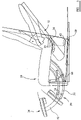
Figure 1 illustrates an adjustable chair in accordance with one embodiment of the invention; -
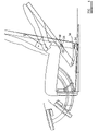
Figure 2 illustrates some of the components of the chair ofFigure 1 ; -
Figures 3 and4 illustrate alternative designs of a chair, not according to the invention; -
Figure 5 illustrates, diagrammatically, part of an arrangement suitable for use in the chairs ofFigures 1 to 4 ; -
Figure 6 is a diagrammatic view of a piece of furniture not according to the invention; and -
Figure 7 is a diagrammatic view illustrating one side of the piece of furniture, not according to the invention. - The chair illustrated in
Figures 1 and2 is an adjustable chair of the motorised form and comprises a number of relatively movable chair components. Specifically, the chair comprises aseat pad component 10 which is angularly movable between a position in which it lies generally horizontally (as shown), and a tilted or inclined position in which it is raised to assist a user in moving from a seated position to a standing position. The chair further comprises an adjustableback rest component 12 and an adjustablefoot rest component 14. - In the arrangement illustrated in
Figure 1 , theseat pad 10 comprises a pair of seatpad side members 16 between which is secured a seatpad support member 18, the upper surface of which carries a suitably padded and upholsteredcushion 20. Thesupport members 16 each carry two pairs ofrollers 22 which, in use, are able to ride withinarcuate guide grooves 24 provided in basecomponent side members 26 of abase component 28. - The
base component 28 andseat pad 10 include respectivemotor mounting brackets brackets seat pad 10 occupies substantially the position illustrated to an extended condition, then theseat pad 10 will be moved, therollers 22 acting as followers, being guided for movement within the respectivearcuate grooves 24 to cause theseat pad 10 to move from the generally horizontal position illustrated to an inclined position, theseat pad 10 moving through a pivot-like motion about a pivot point defined by the centre of curvature of the twoarcuate grooves 24. - As illustrated, the seat
pad side members 16 are each provided with anarcuate groove 34 within which a pair ofrollers 36 carried by abracket 38 can move, thebracket 38 serving to support the seat back 12. It will be appreciated, therefore, that theseat back 12 is guided for pivot-like movement relative to theseat pad 10 about a pivot point located at the centre of curvature of thearcuate groove 34. Thebracket 38 and seatpad side members 16 are provided withmounting brackets 40 between which an actuator is connected and, as with theseat pad 10, adjustment of the length of the actuator causes therollers 36 to move within thearcuate groove 34 to adjust the angle of inclination of the seat back 12. - The
foot rest 14 is mounted upon abracket 42 having a pair ofrollers 44 secured thereto, therollers 44 being located within anarcuate groove 46 formed in the basecomponent side member 26. Thebracket 42 further serves as a mounting bracket for a motor device, the other end of which is secured to amounting bracket 48 associated with thebase component 28 to drive thefoot rest 42 between a substantially vertical orientation as illustrated inFigures 1 and2 and a substantially horizontal configuration. - It will be appreciated that from the position illustrated in
Figure 1 , if desired a user can operate the motors of the chair to cause thefoot rest 14 to be driven from the position illustrated towards a substantially horizontal configuration, therollers 44 riding within theguide groove 46 to support and guide thefoot rest 14 through such movement. The back rest can be adjusted between the substantially vertical position illustrated and a reclined position by operation of the appropriate motor to cause therollers 36 to ride along the length of thearcuate groove 34, therollers 36 andgroove 34 serving to guide and support theback rest 12 through such movement. The movement of thefoot rest 14 may be controlled independently of the movement of theback rest 12, if desired. Further, from the position illustrated inFigure 1 theseat pad 10 may be moved to an inclined position, therollers 22 moving within thearcuate grooves 24 to guide and support theseat pad 10 through such movement, the movement of theseat pad 10 serving to assist a user in moving from a seated position towards a standing position. During the movement of the seat pad, if desired, the position of theseat back 12 relative to theseat pad 10 may also be adjusted so as to ensure that the position of theseat back 12 does not interfere with the movement of the user towards a standing position. - It will be appreciated that as the paths of movement of the various components of the chair are determined by the shape and position of the
grooves seat pad 10 to follow a pivot-like course of movement about a pivot point located at the position of the user's knees. As the user's knees project, in use, in front of the chair, such design is not usually possible. However, with the furniture of the present invention, the shapes and positions of thegrooves 24 can be selected so as to achieve such movement. - Likewise, the position of the point about which the foot rest 14 pivots can be chosen at will. Similarly, the position of the affective pivotal connection of the
back rest 12 to theseat pad 10 can be selected at will so as to be located at approximately the position of the user's hips. - The design is advantageous in that the provision of a complex, typically metallic, support structure for the various moving components of the chair can be avoided. The weight and cost of the furniture can thus be reduced which has obvious benefits. Although in the arrangement described hereinbefore the various components are arranged to undertake relative pivot-like movement, it will be appreciated that by appropriate selection of the shapes and positions of the
grooves -
Figure 3 illustrates an alternative design of chair. In the design illustrated inFigure 3 , theseat pad 10 is not designed to move from a generally horizontal position to an inclined position, but rather is intended to remain in its substantially horizontal configuration in normal use. Theback rest 12 is secured to theseat pad 10 by an arrangement similar to that illustrated inFigure 1 but in which threerollers 36 are secured to theback rest 12, the threerollers 36 being movable within the arcuate groove orslot 34. - The
foot rest 14 is supported by atelescopic guide arrangement 50. Thetelescopic guide arrangement 50 comprises anarcuate follower member 52 secured to thefoot rest 14 and supported for sliding movement by guide means in the form of threerollers 54. The guide means 54, in turn, are supported upon an arcuateauxiliary follower member 56 which, in turn, is supported upon guide means in the form of a further set of threeroller members 58 carried by the seatpad side members 16. The provision of atelescopic guide arrangement 50 is advantageous in that the entire guide arrangement associated with thefoot rest 14 can be housed beneath theseat pad 10. In the arrangement illustrated inFigure 1 , it will be appreciated that part of the guide arrangement for thefoot rest 14 extends above the height of theseat pad 10 and is housed within part of thebase component 28 which may result in an increase in the dimensions and complexity of the base component. - The arrangement illustrated in
Figure 3 is designed such that when theseat back 12 is moved from its upright configuration to a reclined configuration, the remainder of the chair is moved forwards. Consequently, the furniture can be positioned adjacent a wall and movement of the seat back 12 to a reclined position does not result in the seat back 12 contacting the wall surface as the remainder of the chair moves forward to accommodate such movement. In the arrangement illustrated inFigure 3 , this is achieved by supporting the chair upon abase component 60 by supporting the chair upon rollers, and by using abelt 62 secured to thebase component 60, wrapped around one of the rollers and secured to a lower end of the seat back 12 to drive the chair for movement relative to thebase component 60, movement of the seat back 12 to its reclined position driving the chair forwardly relative to thebase 60. -
Figure 4 illustrates another design of chair which is very similar to that ofFigure 3 . m the arrangement illustrated inFigure 4 , theseat back 12 is supported by a pair ofgrooves 34, each of which accommodates asingle roller 36. Thegrooves 34 are concentric about a pivot axis about which the seat back 12 moves, in use. - Although in the arrangements described hereinbefore the
rollers liners 60 may be provided (as shown inFigure 5 ) to assist in the smooth movement of therollers liners 60 may increase the range of materials suitable for use in the invention. Theliners 60 conveniently includeshoulders 62 serving to retain the associated rollers within the grooves. It may, further, be possible to avoid using rollers and instead provide slides slidable within the lined grooves. - Referring to
Figure 6 there is illustrated an article of furniture in the form of anarmchair 110. Although the article of furniture in this case is anarmchair 110, it will be appreciated that the invention described herein is equally applicable to other forms of furniture, for example to sofas or to beds. Thechair 110 comprises an outer frame orsupport 112 including a pair of side walls. An inner frame orsupport 114 is secured within theouter support 112 for movement relative thereto. The mounting of theinner support 114 to theouter support 112 is in the form ofrollers 116 carried by theinner support 114 which are received withinguide grooves 118 formed in theouter support 112. It will be appreciated that theinner support 114 is able to move relative to theouter support 112 along a path of movement defined by the shapes and relative orientations of thegrooves 118 and, in the arrangement illustrated, the path of movement is an angled translatory movement, theinner support 114 being movable upwards and forwards from one position to another. - The
inner support 114 carries the seat pad of thechair 110. The inner andouter supports Figure 7 , preferably each include a pair of side walls 112a, 114a, which lie parallel and adjacent one another. - The
chair 110 further comprises aback support 110 which is mounted for movement between an upright position and a reclined position. Theback support 120 is provided with a series of rollers located within a guide groove formed in theinner support 114 in the manner described hereinbefore, to guide theback support 120 for reclining movement relative to theinner support 114. Theback support 120 is further provided withsimilar rollers 122 received within grooves orslots 124 formed in theouter support 112, and it will be appreciated that the angle of theback support 120 is dependent upon the position of theinner support 114 relative to theouter support 112 at any given time. - Connected to the
inner support 114 is afoot rest assembly 126 of form substantially identical to that described hereinbefore, but including an additional telescopic component and four support bearings, thefoot rest assembly 26 being movable between a substantially vertical, rest configuration and a substantially horizontal, in use configuration. - The
chair 110 further comprises amotor 128 of the form including a threaded shaft rotatable by the motor, rotation of the shaft causing a nut component to translate along the length of the shaft. The nut component is secured to anoutput component 130 having abracket 132 formed thereon to which adrive bar 134 is secured, thedrive bar 134 being secured at its opposite end to thefoot rest assembly 126. In use. operation of themotor 128 drives thefoot rest 126 between its rest and in use configurations. - As illustrated in
Figure 6 , theinner support 114 includes an abutment 136 with which thecomponent 130 is engageable at the time at which thefoot rest 126 reaches its in use configuration. Once thecomponent 130 has moved into engagement with the abutment 136, further operation of themotor 128 results in the abutment 136, and hence the inner support 141 being driven from its rearward position to its forward, raised position. As described hereinbefore, such movement of theinner support 114 results in theback support 120 being driven from its upright condition to its reclined condition. Further, as thefoot rest 126 is secured to theinner support 114, it will be appreciated that the movement of theinner support 114 results in similar translatory movement of thefoot rest 126. It will thus be appreciated that asingle motor 128 can be used to drive both thefoot rest 126 between its rest and in use conditions, and to drive thechair 110 between its upright and reclined configurations. - In order to return the
chair 110 to its upright configuration, themotor 128 is driven in the reverse direction. The weight of the inner support 114 (and the user if seated upon the chair) results in theinner support 114 translating along the angled path defined by thegrooves 18 towards its rearward position which, in turn, results in theback support 120 returning to its upright position. Once theinner support 114 has reached its rearward position, further operation of themotor 128 serves to retract thefoot rest 126. It will be appreciated that thechair 110 has a number of advantages. Firstly, a single motor can be used to drive thefoot rest 126 and drive thechair 110 between its upright and reclined configurations. Secondly, it will be appreciated that the chair when in its reclined position does not project significantly further rearward than when in its upright condition. Consequently, thechair 110 is of substantially zero wall form. Further, as thefoot rest 126 is deployed prior to commencement of reclining movement of thechair 110, it will be appreciated that thefoot rest 126 can be used both with the chair in its upright configuration and with the chair in its reclined configuration. - A number of other modifications and alterations may be made to the arrangements described hereinbefore without departing from the scope of the invention, as defined by the appended claims.
Claims (4)
- Adjustable chair of the motorized form comprising a base component (28) a pair of side support members (16), between which is secured a seat pad support member (18), a seat pad (10), a backrest (12), and a foot rest (14), wherein the seat pad (10) is secured to the side support members (16), the side support members 16 each carry at least two pairs of rollers (22), which, in use, each pair (22) ride within respective arcuate grooves (24) of a pair of arcuate grooves (24) provided in side members (26) of the base component 28 such that the seat pad (10) can pivotally move about a pivot point defined by the centre of curvature of the two arcuate grooves (24) from the general horizontal position to an inclined position under the operation of an actuator connected to the seat pad (10) and base component 28 via respective motor mounting brackets (30,32), the backrest (12) being guided for pivot-like movement relative to the seat pad (10) by means of a pair of rollers (36) carried by a bracket (38) provided on the backrest (12) and a guide (34) provided on the side support members (16), the pivot-like movement being about a pivot point located at the center of curvature of the arcuate groove (34) under the operation of an actuator connected to the bracket (38) and side members (16) via mounting brackets (40), the foot rest 14 mounted upon a bracket (42) having a pair of rollers (44) secured thereto, the rollers being located within arcuate groove (46) formed in the side member 26, the bracket (42) serving as a mounting bracket for a motor device, the other end of the motor device being secured to a mounting bracket 48 associated with the base component the motor device driving the foot rest (12) between substantially vertical and horizontal orientations.
- Adjustable chair according to Claim 1, wherein at least two rollers are provided, the rollers being in a fixed relationship to one another.
- Adjustable chair according any preceding claim wherein the guide comprises an elongate slot or groove in which the roller(s) are located.
- Adjustable chair according to any of the preceding claims, wherein the arcuate guide has a fixed radius of curvature for relative pivoting-like movement about a pivot axis located at the centre of curvature of the guide.
Applications Claiming Priority (3)
| Application Number | Priority Date | Filing Date | Title |
|---|---|---|---|
| GBGB0708053.4A GB0708053D0 (en) | 2007-04-26 | 2007-04-26 | Adjustable furniture |
| GBGB0803049.6A GB0803049D0 (en) | 2007-04-26 | 2008-02-20 | Furniture |
| PCT/GB2008/001504 WO2008132481A2 (en) | 2007-04-26 | 2008-04-28 | Adjustable furniture |
Publications (2)
| Publication Number | Publication Date |
|---|---|
| EP2142048A2 EP2142048A2 (en) | 2010-01-13 |
| EP2142048B1 true EP2142048B1 (en) | 2022-08-24 |
Family
ID=38170700
Family Applications (1)
| Application Number | Title | Priority Date | Filing Date |
|---|---|---|---|
| EP08737140.7A Active EP2142048B1 (en) | 2007-04-26 | 2008-04-28 | Adjustable chair |
Country Status (5)
| Country | Link |
|---|---|
| US (2) | US9474375B2 (en) |
| EP (1) | EP2142048B1 (en) |
| ES (1) | ES2928799T3 (en) |
| GB (5) | GB0708053D0 (en) |
| WO (1) | WO2008132481A2 (en) |
Cited By (1)
| Publication number | Priority date | Publication date | Assignee | Title |
|---|---|---|---|---|
| TWI844413B (en) * | 2023-06-26 | 2024-06-01 | 國立屏東科技大學 | Assisted standing chair and method of use thereof |
Families Citing this family (24)
| Publication number | Priority date | Publication date | Assignee | Title |
|---|---|---|---|---|
| GB0708053D0 (en) | 2007-04-26 | 2007-06-06 | Leuven | Adjustable furniture |
| GB0918685D0 (en) | 2009-10-23 | 2009-12-09 | Integrated Furniture Technolog | Adjustable furniture |
| US8403415B2 (en) * | 2010-08-16 | 2013-03-26 | Be Aerospace, Inc. | Aircraft passenger seat recline mechanism |
| GB201015084D0 (en) | 2010-09-09 | 2010-10-27 | Integrated Furniture Technologies Ltd | Lift-recliner chair |
| JP5998883B2 (en) * | 2012-05-28 | 2016-09-28 | トヨタ紡織株式会社 | Vehicle seat |
| WO2014027774A1 (en) * | 2012-08-17 | 2014-02-20 | Jang Myung Su | Shampoo chair having seat |
| US20140210251A1 (en) * | 2013-01-29 | 2014-07-31 | Billy Joe Griggs, Jr. | Assist mechanism for recliner closing |
| US9420894B2 (en) * | 2013-05-29 | 2016-08-23 | Flexsteel Industries Inc. | Convertible seat/bed having noncoplanar bed base sections |
| CN106414240B (en) * | 2014-04-02 | 2020-12-29 | Be航天公司 | Bracket tilt mechanism for aircraft seats with fixed shells |
| EP3193671B1 (en) * | 2014-09-18 | 2019-06-12 | Motion Concepts L.P. | Adjustable chair |
| GB2533217A (en) | 2014-12-11 | 2016-06-15 | Integrated Furniture Tech Ltd | Adjustable furniture |
| GB201504140D0 (en) | 2015-03-11 | 2015-04-22 | Motus Mechanics Ltd | Adjustable bed |
| US12575682B2 (en) | 2015-03-11 | 2026-03-17 | Motus Mechanics Ltd. | Adjustable furniture |
| GB201610212D0 (en) | 2016-06-13 | 2016-07-27 | Motus Mech Ltd | Adjustable bed |
| CN104840032B (en) * | 2015-05-27 | 2017-11-17 | 山东英吉多健康产业有限公司 | Seat, 0 90 ° of back cushion linkage regulation adjustable training stools |
| GB201813009D0 (en) | 2018-08-09 | 2018-09-26 | Eevolv Ltd | A drive mechanism |
| GB201901010D0 (en) | 2019-01-24 | 2019-03-13 | Eevolv Ltd | Lay-flat chair |
| GB2586142B (en) | 2019-08-07 | 2023-04-12 | Safran Seats Gb Ltd | Aircraft seat and cam followers |
| US12036161B2 (en) | 2019-08-16 | 2024-07-16 | Stryker Corporation | Patient support with deck width monitoring and control |
| TWM589493U (en) * | 2019-09-05 | 2020-01-21 | 林長貞 | Seat composition structure |
| US11130578B1 (en) * | 2019-10-24 | 2021-09-28 | B/E Aerospace, Inc. | Adjustable ottoman |
| US11827362B2 (en) * | 2020-08-18 | 2023-11-28 | B/E Aerospace, Inc. | Device to resolve angled ottoman configuration |
| DE102020126675A1 (en) | 2020-10-12 | 2022-04-14 | Bayerische Motoren Werke Aktiengesellschaft | Vehicle guidance system and method for operating a driving function following a start-up process |
| US20240225285A1 (en) * | 2023-01-10 | 2024-07-11 | Current Products Company, LLC | Reclining chair with cartridge |
Citations (8)
| Publication number | Priority date | Publication date | Assignee | Title |
|---|---|---|---|---|
| DE801527C (en) * | 1949-09-04 | 1951-01-11 | Fritz Birker | Seating that can be converted into a double bed |
| DE1163510B (en) * | 1957-08-14 | 1964-02-20 | Ernst Helbig | Seating convertible into a lounger |
| US4013257A (en) * | 1975-04-17 | 1977-03-22 | The Shaw-Walker Company | Chair control |
| EP0217488A2 (en) * | 1985-09-13 | 1987-04-08 | Contour Chair-Lounge Co., Inc. | Adjustable chair |
| DE9315337U1 (en) * | 1993-10-11 | 1994-02-03 | Bitsch, Hans-Ullrich, Prof. Dipl.-Designer, 40545 Düsseldorf | Seating furniture, in particular office swivel chair with inclination adjustment of the seat and backrest |
| JP2000116458A (en) * | 1998-10-20 | 2000-04-25 | Itoki Crebio Corp | Member journaling structure for chair |
| US20010028183A1 (en) * | 1999-04-23 | 2001-10-11 | L&P Property Management Company | Motorized reclinig mechanism and furniture item |
| GB2418846A (en) * | 2004-10-07 | 2006-04-12 | Alfred William Arthurs | Chair incorporating a mechanism to assist rising |
Family Cites Families (114)
| Publication number | Priority date | Publication date | Assignee | Title |
|---|---|---|---|---|
| US349089A (en) | 1886-09-14 | Invalid-lounge | ||
| US638466A (en) | 1899-09-30 | 1899-12-05 | J A Kelly & Bros Inc | Sofa-bedstead. |
| US809944A (en) * | 1904-02-01 | 1906-01-16 | James E Hanger | Chair. |
| US912214A (en) | 1908-07-18 | 1909-02-09 | Lloyd W Ward | Invalid-bed. |
| US942354A (en) | 1909-06-14 | 1909-12-07 | John G Ryan | Head-rest for beds. |
| US1075154A (en) | 1913-02-01 | 1913-10-07 | George H Mansfield | Snow-remover. |
| GB191322022A (en) | 1913-09-30 | 1914-08-20 | Albert Tyzack | Improvements in or connected with Reclining Chairs having Adjustable Seats and Backs. |
| GB101239A (en) | 1916-02-15 | 1916-08-31 | Albert Glenister | Improvements in or relating to Chairs, Couches or the like. |
| US1238078A (en) | 1916-06-06 | 1917-08-28 | Harvey N Ault | Adjustable chair. |
| GB173772A (en) | 1921-01-04 | 1922-12-14 | Albert Edwin Gell | Improvements in reclining adjustable chairs and seats |
| US1802609A (en) * | 1929-03-12 | 1931-04-28 | Krause Max | Chair |
| GB329834A (en) | 1929-05-17 | 1930-05-29 | Abraham Hart | Improvements in or relating to chairs, seats and the like |
| GB392165A (en) * | 1931-11-10 | 1933-05-10 | Frederick William Lockley Tota | Improvements in and connected with adjustable seats |
| GB414464A (en) | 1933-03-28 | 1934-08-09 | H J Searle & Son Ltd | Improvements in and relating to adjustable chairs and settees |
| US2497395A (en) * | 1946-03-04 | 1950-02-14 | Sr Roy A Cramer | Reclining chair |
| GB617443A (en) * | 1946-10-01 | 1949-02-07 | Vickers Armstrongs Ltd | Improvements relating to adjustable chairs and other seats |
| GB775679A (en) | 1954-06-15 | 1957-05-29 | Greaves & Thomas Ltd | Improvements in and relating to reclining chairs |
| GB794138A (en) * | 1955-12-20 | 1958-04-30 | Res Interests Ltd | Improvements in or relating to reclining chairs |
| US2954072A (en) | 1956-07-17 | 1960-09-27 | Fossati Mario | Hinged rods mechanism for reclinable armchairs |
| GB863490A (en) * | 1956-08-03 | 1961-03-22 | Peter Stewart Fletcher | Improvements in or relating to adjustable reclining chairs and like articles of furniture |
| GB840195A (en) * | 1957-11-12 | 1960-07-06 | Res Interests Ltd | Improvements in or relating to reclining chairs |
| US3086814A (en) | 1959-06-15 | 1963-04-23 | Anton Lorenz | Reclining chair of the multiple movement type |
| DE1404651C3 (en) | 1959-09-17 | 1975-07-24 | Fridtjof F. 1000 Berlin Schliephacke | Reclining armchair with swiveling leg support |
| US3202453A (en) | 1963-07-09 | 1965-08-24 | Ford Motor Co | Retractable seat |
| US3269767A (en) | 1963-10-18 | 1966-08-30 | Marzocchi Lorenzo | Folding-frame chair |
| FR1596508A (en) * | 1968-07-18 | 1970-06-22 | ||
| US3869169A (en) * | 1973-06-28 | 1975-03-04 | Pontiac Furniture Ind | Retractable footrest mechanism |
| US3873152A (en) | 1974-01-09 | 1975-03-25 | John Garas | Adjustable orthopedic lounger |
| ZA763060B (en) * | 1975-08-11 | 1977-04-27 | Hoover Seng Co | Reclining chair |
| US4212495A (en) * | 1979-01-26 | 1980-07-15 | Sears, Roebuck & Co. | Reclining chair |
| DE2933160C2 (en) | 1979-08-16 | 1986-08-14 | Keiper Recaro GmbH & Co, 7312 Kirchheim | Leg support for vehicle seats |
| US4332417A (en) * | 1979-12-06 | 1982-06-01 | Hoover Universal, Inc. | Reclining actuator for a recliner chair |
| US4365836A (en) * | 1980-08-29 | 1982-12-28 | Cleveland Chair Company | Motorized reclining chair |
| FR2527061B1 (en) | 1982-05-19 | 1985-11-15 | Ami | ARTICULATED SEAT |
| EP0107882B1 (en) | 1982-10-28 | 1986-07-23 | FLIGHT EQUIPMENT & ENGINEERING LIMITED | Vehicle seats |
| DD214758A1 (en) * | 1983-04-21 | 1984-10-24 | Polstermoebelkombinat Oelsa Ra | SINGLE ARMCHAIR WITH MECHANISM FOR TRANSFORMING IN A LYING CHAIR BY WEIGHT TRANSFER OF THE USERS PERSON |
| DE3440634C2 (en) | 1984-11-07 | 1986-09-11 | J.M. Voith Gmbh, 7920 Heidenheim | Device for double-sided coating of moving webs |
| SE460011B (en) * | 1986-12-01 | 1989-09-04 | Anders Moeller | CHAIR BEFORE PLACING A PERSON IN THE DESIRED DOCTOR |
| US4904019A (en) * | 1987-10-01 | 1990-02-27 | Super Sagless Corporation | Three-way recliner |
| JPH01214308A (en) | 1988-02-23 | 1989-08-28 | Kunimatsu Kogyo Kk | Reclining seat |
| US5466046A (en) * | 1988-05-20 | 1995-11-14 | La-Z-Boy Chair Co. | Linear actuation drive mechanism for power-assisted chairs |
| US5058954A (en) * | 1988-07-07 | 1991-10-22 | Kan Chee Lee | Body contour support structure for travelers and audiences |
| JPH0289947U (en) | 1988-12-28 | 1990-07-17 | ||
| US5246266A (en) | 1990-09-18 | 1993-09-21 | Chairworks Taiwan Limited | Chair |
| GB9209372D0 (en) | 1992-04-30 | 1992-06-17 | Smith Karl W | "stand-easy",(a lifting chair for static and wheeled use by the infirm) |
| DE4224458A1 (en) * | 1992-07-24 | 1994-01-27 | Brose Fahrzeugteile | Seat cushion adjustment for vehicle seat - has mechanical drive providing movement between two extreme positions |
| DE4225286A1 (en) * | 1992-07-31 | 1994-02-03 | Steltemeier Gmbh | Convertible chair and recliner with chair frame retractable from furniture frame - has backrest frame movable on furniture frame, and horizontal supports with two pairs of castors moving along bar |
| GB2271053A (en) | 1992-09-30 | 1994-04-06 | Edward L Stulik | Reclining chair |
| DE9300997U1 (en) * | 1993-01-26 | 1994-05-26 | Sondergeld, Horst, 79106 Freiburg | Adjustable seat |
| NL9400473A (en) | 1994-03-25 | 1995-11-01 | Adrianus Henricus Marinus Joha | Assembly comprising at least two supporting parts, chair, table or prosthesis, containing an assembly of this nature |
| US5558399A (en) * | 1994-09-13 | 1996-09-24 | Serber; Hector | Seat and lumbar motion chair, assembly and method |
| NO300754B1 (en) | 1994-10-14 | 1997-07-21 | Handicare Ind As | Adjustable chair |
| GB9425078D0 (en) | 1994-12-13 | 1995-02-08 | British Airways Plc | A seating unit |
| JP3605161B2 (en) | 1994-12-21 | 2004-12-22 | シロキ工業株式会社 | Reclining device |
| GB9500022D0 (en) * | 1995-01-04 | 1995-03-01 | Unwalla Jamshed | Integrated seat and back and mechanism for chairs |
| JPH08308680A (en) | 1995-05-17 | 1996-11-26 | Tenryu Ind Co Ltd | Leg rest for vehicle seat |
| IT1282278B1 (en) | 1995-12-29 | 1998-03-16 | Bortoluzzi Mobili Srl | BED WITH SUPPORT PLATFORM WITH RECLINING SECTIONS USING A SEMI-AUTOMATIC MANUALLY OPERATED MECHANISM |
| EP0801913A1 (en) | 1996-04-16 | 1997-10-22 | Cke Technologies Inc. | Backrest for chair |
| US5895093A (en) * | 1996-05-07 | 1999-04-20 | Casey; Kenneth | Recliner lift chair with swivel base |
| US5967609A (en) * | 1996-11-18 | 1999-10-19 | Hwe, Inc. | Reclining chair with guide rail system |
| DE19711944C2 (en) | 1997-03-21 | 2000-08-31 | Girsberger Holding Ag Buetzber | Vehicle seat |
| US5897462A (en) | 1997-04-18 | 1999-04-27 | St. Germain; Robert J. | Exercise apparatus |
| DE59806685D1 (en) | 1997-07-16 | 2003-01-30 | Huelsta Werke Huels Kg | Bed slatted frame with adjustable grate parts |
| DE29715343U1 (en) | 1997-08-27 | 1997-11-27 | Unimet Zentrallager Nord GmbH & Co. KG, 28876 Oyten | Seating furniture, in particular garden armchairs |
| US6106065A (en) * | 1997-10-24 | 2000-08-22 | Reliance Medical Products, Inc. | Examination chair with lifting and tilting mechanism |
| JPH11244096A (en) | 1998-03-06 | 1999-09-14 | Tsunayoshi Morikawa | Reclining bed with waist sliding mechanism |
| DE29808584U1 (en) | 1998-05-13 | 1998-10-22 | Mühlberger, Dieter, Dipl.-Designer (FH), 55546 Frei-Laubersheim | Mechanism for lifting and then tilting the seat (stand-up aid) of a seat or armchair |
| US6227489B1 (en) * | 1998-05-15 | 2001-05-08 | Koito Industries, Ltd. | Aircraft seat apparatus |
| DE19906547B4 (en) | 1999-02-17 | 2004-03-25 | Innovint Einrichtungs Gmbh | Child seat for mobile use in an aircraft |
| US6203106B1 (en) * | 1999-05-17 | 2001-03-20 | Activeaid, Inc. | Chair for handicapped individuals |
| IT1306152B1 (en) * | 1999-06-02 | 2001-05-30 | Aviointeriors Spa | ARMCHAIR WITH PERFECTED CRADLE MOVEMENT, IN PARTICULAR AIRCRAFT. |
| JP3609996B2 (en) * | 1999-10-12 | 2005-01-12 | エース家具工業株式会社 | sofa |
| DE60117923T2 (en) * | 2000-01-14 | 2006-09-14 | BE Aerospace, Inc., Wellington | Passenger seat with variable seat |
| US6347420B2 (en) | 2000-04-12 | 2002-02-19 | Franklin E. Elliott | System for producing anthropometric, adjustable, articulated beds |
| AU9137401A (en) | 2000-11-18 | 2002-05-23 | Moon Ho Choi | Safety device for car seat |
| GB0101239D0 (en) | 2001-01-17 | 2001-02-28 | 3M Innovative Properties Co | Medicinal aerosols |
| JP2003199641A (en) | 2001-01-25 | 2003-07-15 | Hirobumi Tada | Reclining device |
| WO2002076367A2 (en) | 2001-03-27 | 2002-10-03 | Hill-Rom Services, Inc. | Hospital bed |
| US6692069B2 (en) * | 2001-07-20 | 2004-02-17 | B E Aerospace, Inc. | Aircraft sleeper seat |
| CA2625280C (en) | 2001-08-09 | 2010-08-03 | Virgin Atlantic Airways Limited | A seating system and a passenger accomodation unit for a vehicle |
| JP4902070B2 (en) | 2001-08-22 | 2012-03-21 | コンビ株式会社 | child seat |
| DE20117344U1 (en) | 2001-10-20 | 2002-01-03 | Stanzwerk Wetter Sichelschmidt GmbH & Co. KG, 58300 Wetter | seating |
| US20030172455A1 (en) | 2002-03-18 | 2003-09-18 | Roma John K. | Spring-assisted futon frame |
| JP2003310666A (en) | 2002-04-23 | 2003-11-05 | Tomi Mino | Bed |
| US6739661B1 (en) | 2002-07-15 | 2004-05-25 | David N. Dukes | Pivotable reclining child safety car seat |
| JP3967710B2 (en) * | 2003-03-04 | 2007-08-29 | 博文 多田 | Reclining device |
| DE10318759B3 (en) * | 2003-04-25 | 2004-07-29 | Armin Sander | Office chair with pivoted backrest support and synchronous mechanism for adjustment of seat position simultaneous with adjustment of backrest |
| DE20308723U1 (en) | 2003-06-04 | 2003-08-07 | Arnold, Günter, 24977 Langballig | chair |
| GB0325358D0 (en) | 2003-10-30 | 2003-12-03 | Peter Cook Internat Plc | Powered furniture |
| GB2409607A (en) | 2003-12-23 | 2005-06-29 | Symbian Ltd | Caller ID using a movie clip |
| JP2005192763A (en) * | 2004-01-07 | 2005-07-21 | Kariya Mokuzai Kogyo Kk | Chair |
| GB2415759B (en) | 2004-06-29 | 2007-06-13 | Newfrey Llc | A threaded insert |
| DE602005026608D1 (en) | 2004-07-30 | 2011-04-14 | Hill Rom Services Inc | Advanced articulation system and mattress topper for a bed |
| AU2005277594A1 (en) | 2004-08-16 | 2006-03-02 | Hill-Rom Services, Inc. | Chair |
| DE102005016943B4 (en) | 2005-04-12 | 2006-11-30 | Stanzwerk Wetter Sichelschmidt Gmbh & Co. Kg | Ottoman |
| NZ565820A (en) | 2005-08-04 | 2010-10-29 | Heka Dental Aps | A chair or a bed having a seat, a backrest and an armrest as well as use thereof |
| EP1951547B1 (en) | 2005-11-21 | 2015-07-08 | Nightgear LLC | Seating accessory |
| US7585018B2 (en) | 2006-01-10 | 2009-09-08 | La-Z-Boy Incorporated | Wall proximity reclining chair with in-line linkage mechanism |
| US7703851B2 (en) | 2006-09-21 | 2010-04-27 | Mazda Motor Corporation | Seat device |
| ES2322301T3 (en) | 2006-10-06 | 2009-06-18 | Stoll Giroflex Ag | SYNCHRONIZED OFFICE CHAIR. |
| US7445279B2 (en) | 2006-11-13 | 2008-11-04 | L & P Property Management Company | Pivot-over-arm reclining mechanism for a seating unit |
| JP2008149858A (en) | 2006-12-15 | 2008-07-03 | Toyota Motor Corp | Vehicle seat device |
| US7766421B2 (en) | 2006-12-21 | 2010-08-03 | L & P Property Management Company | Recliner lift chair with power lift and reclining units |
| GB0704546D0 (en) | 2007-03-08 | 2007-04-18 | Contour Premium Aircraft Seati | Adjustable seat |
| GB0708053D0 (en) | 2007-04-26 | 2007-06-06 | Leuven | Adjustable furniture |
| DE102007024218A1 (en) | 2007-05-11 | 2008-11-13 | Appeltshauser, Georg, Dipl.-Ing. | Seating furniture e.g. armchair, has head element adjustable as whole in height relative to seat part, where head element is adjustable by guide along carrier for head element, and guide runs curvedly in adjustment direction of head element |
| DE102007024210A1 (en) | 2007-05-15 | 2008-11-27 | Pilz Gmbh & Co. Kg | Optoelectronic sensor to protect a hazardous area |
| US7698761B2 (en) | 2008-02-04 | 2010-04-20 | L&P Property Management Company | Adjustable bed having four linear actuators |
| GB0918685D0 (en) | 2009-10-23 | 2009-12-09 | Integrated Furniture Technolog | Adjustable furniture |
| GB2486335A (en) | 2009-08-18 | 2012-06-13 | Integrated Furniture Technologies Ltd | Adjustable furniture with guide and follower means |
| US8226162B2 (en) | 2009-09-11 | 2012-07-24 | Campbell Corey A | Child safety seat |
| US8403415B2 (en) | 2010-08-16 | 2013-03-26 | Be Aerospace, Inc. | Aircraft passenger seat recline mechanism |
| US8534758B2 (en) | 2010-09-13 | 2013-09-17 | Tropitone Furniture Co., Inc. | Reclinable seating apparatus and method |
| GB2496597B (en) | 2011-11-14 | 2017-10-04 | Bio-Check(Uk) Ltd | Cartridge for containing a sample |
-
2007
- 2007-04-26 GB GBGB0708053.4A patent/GB0708053D0/en not_active Ceased
-
2008
- 2008-02-20 GB GBGB0803049.6A patent/GB0803049D0/en not_active Ceased
- 2008-04-28 US US12/597,080 patent/US9474375B2/en active Active
- 2008-04-28 EP EP08737140.7A patent/EP2142048B1/en active Active
- 2008-04-28 WO PCT/GB2008/001504 patent/WO2008132481A2/en not_active Ceased
- 2008-04-28 ES ES08737140T patent/ES2928799T3/en active Active
- 2008-04-28 GB GB0807669.7A patent/GB2450199B/en not_active Expired - Fee Related
-
2012
- 2012-02-13 GB GB1202452.7A patent/GB2486597B/en not_active Expired - Fee Related
- 2012-02-16 GB GB1202643.1A patent/GB2486599B/en not_active Expired - Fee Related
-
2016
- 2016-09-29 US US15/279,544 patent/US20170013966A1/en not_active Abandoned
Patent Citations (8)
| Publication number | Priority date | Publication date | Assignee | Title |
|---|---|---|---|---|
| DE801527C (en) * | 1949-09-04 | 1951-01-11 | Fritz Birker | Seating that can be converted into a double bed |
| DE1163510B (en) * | 1957-08-14 | 1964-02-20 | Ernst Helbig | Seating convertible into a lounger |
| US4013257A (en) * | 1975-04-17 | 1977-03-22 | The Shaw-Walker Company | Chair control |
| EP0217488A2 (en) * | 1985-09-13 | 1987-04-08 | Contour Chair-Lounge Co., Inc. | Adjustable chair |
| DE9315337U1 (en) * | 1993-10-11 | 1994-02-03 | Bitsch, Hans-Ullrich, Prof. Dipl.-Designer, 40545 Düsseldorf | Seating furniture, in particular office swivel chair with inclination adjustment of the seat and backrest |
| JP2000116458A (en) * | 1998-10-20 | 2000-04-25 | Itoki Crebio Corp | Member journaling structure for chair |
| US20010028183A1 (en) * | 1999-04-23 | 2001-10-11 | L&P Property Management Company | Motorized reclinig mechanism and furniture item |
| GB2418846A (en) * | 2004-10-07 | 2006-04-12 | Alfred William Arthurs | Chair incorporating a mechanism to assist rising |
Cited By (1)
| Publication number | Priority date | Publication date | Assignee | Title |
|---|---|---|---|---|
| TWI844413B (en) * | 2023-06-26 | 2024-06-01 | 國立屏東科技大學 | Assisted standing chair and method of use thereof |
Also Published As
| Publication number | Publication date |
|---|---|
| US20170013966A1 (en) | 2017-01-19 |
| US20100132118A1 (en) | 2010-06-03 |
| GB2450199B (en) | 2012-10-17 |
| ES2928799T3 (en) | 2022-11-22 |
| GB2450199A (en) | 2008-12-17 |
| GB0807669D0 (en) | 2008-06-04 |
| GB2486599A (en) | 2012-06-20 |
| WO2008132481A3 (en) | 2009-02-12 |
| GB2486599B (en) | 2012-10-17 |
| US9474375B2 (en) | 2016-10-25 |
| GB201202452D0 (en) | 2012-03-28 |
| GB201202643D0 (en) | 2012-04-04 |
| EP2142048A2 (en) | 2010-01-13 |
| WO2008132481A2 (en) | 2008-11-06 |
| GB0708053D0 (en) | 2007-06-06 |
| GB2486597A (en) | 2012-06-20 |
| GB2486597B (en) | 2012-11-07 |
| GB0803049D0 (en) | 2008-03-26 |
Similar Documents
| Publication | Publication Date | Title |
|---|---|---|
| US9474375B2 (en) | Adjustable furniture | |
| EP3229646B1 (en) | Adjustable furniture | |
| CN110025153B (en) | Reclining seat mechanism with seat extension | |
| EP2878229B1 (en) | Powered rocker and glider recliner linkage mechanisms | |
| US8398168B2 (en) | Powered glider recliner linkage mechanism | |
| US8398165B2 (en) | Powered rocker recliner linkage mechanism | |
| US7918496B2 (en) | Armchair with leg rest that is unseen in a retracted position | |
| TWI558346B (en) | Power actuated wall proximity furniture member | |
| US20090256402A1 (en) | Zero gravity wall hugger recliner | |
| US20240365979A1 (en) | Three motor recliner mechanism with independent seat, back and ottoman | |
| KR101928452B1 (en) | Furniture member with leg rest extension | |
| CN102793396A (en) | Enhanced compatibility for a linkage mechanism | |
| CN106414240A (en) | Cradle recline mechanism for fixed-shell aircraft seat | |
| US12193572B2 (en) | Adjustable chair | |
| EP3219299B1 (en) | Wheelchair | |
| CN108294515A (en) | A kind of seat of double acting power drive | |
| CN219895130U (en) | Lifting base and seat unit | |
| GB2537799A (en) | Adjustable furniture | |
| GB2534122A (en) | Adjustable furniture | |
| GB2533431A (en) | Adjustable furniture | |
| HK1246616A1 (en) | Recliner and legrest mechanism for a furniture member |
Legal Events
| Date | Code | Title | Description |
|---|---|---|---|
| PUAI | Public reference made under article 153(3) epc to a published international application that has entered the european phase |
Free format text: ORIGINAL CODE: 0009012 |
|
| 17P | Request for examination filed |
Effective date: 20091117 |
|
| AK | Designated contracting states |
Kind code of ref document: A2 Designated state(s): AT BE BG CH CY CZ DE DK EE ES FI FR GB GR HR HU IE IS IT LI LT LU LV MC MT NL NO PL PT RO SE SI SK TR |
|
| DAX | Request for extension of the european patent (deleted) | ||
| 19U | Interruption of proceedings before grant |
Effective date: 20160721 |
|
| STAA | Information on the status of an ep patent application or granted ep patent |
Free format text: STATUS: EXAMINATION IS IN PROGRESS |
|
| 19W | Proceedings resumed before grant after interruption of proceedings |
Effective date: 20161212 |
|
| RAP1 | Party data changed (applicant data changed or rights of an application transferred) |
Owner name: INTEGRATED FURNITURE TECHNOLOGIES LIMITED |
|
| 17Q | First examination report despatched |
Effective date: 20161223 |
|
| RAP1 | Party data changed (applicant data changed or rights of an application transferred) |
Owner name: DEWERTOKIN GMBH |
|
| RIC1 | Information provided on ipc code assigned before grant |
Ipc: A47C 1/034 20060101ALI20191104BHEP Ipc: A61G 5/14 20060101AFI20191104BHEP Ipc: A47C 1/032 20060101ALI20191104BHEP Ipc: A47C 1/024 20060101ALI20191104BHEP |
|
| RIN1 | Information on inventor provided before grant (corrected) |
Inventor name: ROBERTSON, DALE |
|
| RAP1 | Party data changed (applicant data changed or rights of an application transferred) |
Owner name: DEWERTOKIN TECHNOLOGY GROUP CO., LTD. |
|
| REG | Reference to a national code |
Ref country code: DE Ref legal event code: R079 Ref document number: 602008064595 Country of ref document: DE Free format text: PREVIOUS MAIN CLASS: A47C0001024000 Ipc: A61G0005140000 |
|
| RIC1 | Information provided on ipc code assigned before grant |
Ipc: A47C 1/035 20060101ALI20211123BHEP Ipc: A47C 1/034 20060101ALI20211123BHEP Ipc: A47C 1/024 20060101ALI20211123BHEP Ipc: A47C 1/032 20060101ALI20211123BHEP Ipc: A61G 5/14 20060101AFI20211123BHEP |
|
| GRAP | Despatch of communication of intention to grant a patent |
Free format text: ORIGINAL CODE: EPIDOSNIGR1 |
|
| STAA | Information on the status of an ep patent application or granted ep patent |
Free format text: STATUS: GRANT OF PATENT IS INTENDED |
|
| INTG | Intention to grant announced |
Effective date: 20220307 |
|
| INTG | Intention to grant announced |
Effective date: 20220316 |
|
| GRAS | Grant fee paid |
Free format text: ORIGINAL CODE: EPIDOSNIGR3 |
|
| GRAA | (expected) grant |
Free format text: ORIGINAL CODE: 0009210 |
|
| STAA | Information on the status of an ep patent application or granted ep patent |
Free format text: STATUS: THE PATENT HAS BEEN GRANTED |
|
| AK | Designated contracting states |
Kind code of ref document: B1 Designated state(s): AT BE BG CH CY CZ DE DK EE ES FI FR GB GR HR HU IE IS IT LI LT LU LV MC MT NL NO PL PT RO SE SI SK TR |
|
| REG | Reference to a national code |
Ref country code: GB Ref legal event code: FG4D |
|
| REG | Reference to a national code |
Ref country code: CH Ref legal event code: EP |
|
| REG | Reference to a national code |
Ref country code: IE Ref legal event code: FG4D |
|
| REG | Reference to a national code |
Ref country code: AT Ref legal event code: REF Ref document number: 1513164 Country of ref document: AT Kind code of ref document: T Effective date: 20220915 Ref country code: DE Ref legal event code: R096 Ref document number: 602008064595 Country of ref document: DE |
|
| REG | Reference to a national code |
Ref country code: ES Ref legal event code: FG2A Ref document number: 2928799 Country of ref document: ES Kind code of ref document: T3 Effective date: 20221122 |
|
| REG | Reference to a national code |
Ref country code: LT Ref legal event code: MG9D |
|
| REG | Reference to a national code |
Ref country code: NL Ref legal event code: MP Effective date: 20220824 |
|
| PG25 | Lapsed in a contracting state [announced via postgrant information from national office to epo] |
Ref country code: SE Free format text: LAPSE BECAUSE OF FAILURE TO SUBMIT A TRANSLATION OF THE DESCRIPTION OR TO PAY THE FEE WITHIN THE PRESCRIBED TIME-LIMIT Effective date: 20220824 Ref country code: PT Free format text: LAPSE BECAUSE OF FAILURE TO SUBMIT A TRANSLATION OF THE DESCRIPTION OR TO PAY THE FEE WITHIN THE PRESCRIBED TIME-LIMIT Effective date: 20221226 Ref country code: NO Free format text: LAPSE BECAUSE OF FAILURE TO SUBMIT A TRANSLATION OF THE DESCRIPTION OR TO PAY THE FEE WITHIN THE PRESCRIBED TIME-LIMIT Effective date: 20221124 Ref country code: NL Free format text: LAPSE BECAUSE OF FAILURE TO SUBMIT A TRANSLATION OF THE DESCRIPTION OR TO PAY THE FEE WITHIN THE PRESCRIBED TIME-LIMIT Effective date: 20220824 Ref country code: LV Free format text: LAPSE BECAUSE OF FAILURE TO SUBMIT A TRANSLATION OF THE DESCRIPTION OR TO PAY THE FEE WITHIN THE PRESCRIBED TIME-LIMIT Effective date: 20220824 Ref country code: LT Free format text: LAPSE BECAUSE OF FAILURE TO SUBMIT A TRANSLATION OF THE DESCRIPTION OR TO PAY THE FEE WITHIN THE PRESCRIBED TIME-LIMIT Effective date: 20220824 Ref country code: FI Free format text: LAPSE BECAUSE OF FAILURE TO SUBMIT A TRANSLATION OF THE DESCRIPTION OR TO PAY THE FEE WITHIN THE PRESCRIBED TIME-LIMIT Effective date: 20220824 |
|
| REG | Reference to a national code |
Ref country code: AT Ref legal event code: MK05 Ref document number: 1513164 Country of ref document: AT Kind code of ref document: T Effective date: 20220824 |
|
| PG25 | Lapsed in a contracting state [announced via postgrant information from national office to epo] |
Ref country code: PL Free format text: LAPSE BECAUSE OF FAILURE TO SUBMIT A TRANSLATION OF THE DESCRIPTION OR TO PAY THE FEE WITHIN THE PRESCRIBED TIME-LIMIT Effective date: 20220824 Ref country code: IS Free format text: LAPSE BECAUSE OF FAILURE TO SUBMIT A TRANSLATION OF THE DESCRIPTION OR TO PAY THE FEE WITHIN THE PRESCRIBED TIME-LIMIT Effective date: 20221224 Ref country code: HR Free format text: LAPSE BECAUSE OF FAILURE TO SUBMIT A TRANSLATION OF THE DESCRIPTION OR TO PAY THE FEE WITHIN THE PRESCRIBED TIME-LIMIT Effective date: 20220824 Ref country code: GR Free format text: LAPSE BECAUSE OF FAILURE TO SUBMIT A TRANSLATION OF THE DESCRIPTION OR TO PAY THE FEE WITHIN THE PRESCRIBED TIME-LIMIT Effective date: 20221125 |
|
| PG25 | Lapsed in a contracting state [announced via postgrant information from national office to epo] |
Ref country code: RO Free format text: LAPSE BECAUSE OF FAILURE TO SUBMIT A TRANSLATION OF THE DESCRIPTION OR TO PAY THE FEE WITHIN THE PRESCRIBED TIME-LIMIT Effective date: 20220824 Ref country code: DK Free format text: LAPSE BECAUSE OF FAILURE TO SUBMIT A TRANSLATION OF THE DESCRIPTION OR TO PAY THE FEE WITHIN THE PRESCRIBED TIME-LIMIT Effective date: 20220824 Ref country code: CZ Free format text: LAPSE BECAUSE OF FAILURE TO SUBMIT A TRANSLATION OF THE DESCRIPTION OR TO PAY THE FEE WITHIN THE PRESCRIBED TIME-LIMIT Effective date: 20220824 Ref country code: AT Free format text: LAPSE BECAUSE OF FAILURE TO SUBMIT A TRANSLATION OF THE DESCRIPTION OR TO PAY THE FEE WITHIN THE PRESCRIBED TIME-LIMIT Effective date: 20220824 |
|
| REG | Reference to a national code |
Ref country code: DE Ref legal event code: R097 Ref document number: 602008064595 Country of ref document: DE |
|
| PG25 | Lapsed in a contracting state [announced via postgrant information from national office to epo] |
Ref country code: SK Free format text: LAPSE BECAUSE OF FAILURE TO SUBMIT A TRANSLATION OF THE DESCRIPTION OR TO PAY THE FEE WITHIN THE PRESCRIBED TIME-LIMIT Effective date: 20220824 Ref country code: EE Free format text: LAPSE BECAUSE OF FAILURE TO SUBMIT A TRANSLATION OF THE DESCRIPTION OR TO PAY THE FEE WITHIN THE PRESCRIBED TIME-LIMIT Effective date: 20220824 |
|
| P01 | Opt-out of the competence of the unified patent court (upc) registered |
Effective date: 20230524 |
|
| PLBE | No opposition filed within time limit |
Free format text: ORIGINAL CODE: 0009261 |
|
| STAA | Information on the status of an ep patent application or granted ep patent |
Free format text: STATUS: NO OPPOSITION FILED WITHIN TIME LIMIT |
|
| 26N | No opposition filed |
Effective date: 20230525 |
|
| PG25 | Lapsed in a contracting state [announced via postgrant information from national office to epo] |
Ref country code: SI Free format text: LAPSE BECAUSE OF FAILURE TO SUBMIT A TRANSLATION OF THE DESCRIPTION OR TO PAY THE FEE WITHIN THE PRESCRIBED TIME-LIMIT Effective date: 20220824 |
|
| REG | Reference to a national code |
Ref country code: CH Ref legal event code: PL |
|
| GBPC | Gb: european patent ceased through non-payment of renewal fee |
Effective date: 20230428 |
|
| PG25 | Lapsed in a contracting state [announced via postgrant information from national office to epo] |
Ref country code: LU Free format text: LAPSE BECAUSE OF NON-PAYMENT OF DUE FEES Effective date: 20230428 |
|
| REG | Reference to a national code |
Ref country code: BE Ref legal event code: MM Effective date: 20230430 |
|
| PG25 | Lapsed in a contracting state [announced via postgrant information from national office to epo] |
Ref country code: MC Free format text: LAPSE BECAUSE OF FAILURE TO SUBMIT A TRANSLATION OF THE DESCRIPTION OR TO PAY THE FEE WITHIN THE PRESCRIBED TIME-LIMIT Effective date: 20220824 |
|
| PG25 | Lapsed in a contracting state [announced via postgrant information from national office to epo] |
Ref country code: GB Free format text: LAPSE BECAUSE OF NON-PAYMENT OF DUE FEES Effective date: 20230428 |
|
| PG25 | Lapsed in a contracting state [announced via postgrant information from national office to epo] |
Ref country code: MC Free format text: LAPSE BECAUSE OF FAILURE TO SUBMIT A TRANSLATION OF THE DESCRIPTION OR TO PAY THE FEE WITHIN THE PRESCRIBED TIME-LIMIT Effective date: 20220824 Ref country code: LI Free format text: LAPSE BECAUSE OF NON-PAYMENT OF DUE FEES Effective date: 20230430 Ref country code: GB Free format text: LAPSE BECAUSE OF NON-PAYMENT OF DUE FEES Effective date: 20230428 Ref country code: CH Free format text: LAPSE BECAUSE OF NON-PAYMENT OF DUE FEES Effective date: 20230430 |
|
| REG | Reference to a national code |
Ref country code: IE Ref legal event code: MM4A |
|
| PG25 | Lapsed in a contracting state [announced via postgrant information from national office to epo] |
Ref country code: BE Free format text: LAPSE BECAUSE OF NON-PAYMENT OF DUE FEES Effective date: 20230430 |
|
| PG25 | Lapsed in a contracting state [announced via postgrant information from national office to epo] |
Ref country code: IE Free format text: LAPSE BECAUSE OF NON-PAYMENT OF DUE FEES Effective date: 20230428 |
|
| PG25 | Lapsed in a contracting state [announced via postgrant information from national office to epo] |
Ref country code: IE Free format text: LAPSE BECAUSE OF NON-PAYMENT OF DUE FEES Effective date: 20230428 |
|
| PG25 | Lapsed in a contracting state [announced via postgrant information from national office to epo] |
Ref country code: IT Free format text: LAPSE BECAUSE OF FAILURE TO SUBMIT A TRANSLATION OF THE DESCRIPTION OR TO PAY THE FEE WITHIN THE PRESCRIBED TIME-LIMIT Effective date: 20220824 |
|
| PGFP | Annual fee paid to national office [announced via postgrant information from national office to epo] |
Ref country code: DE Payment date: 20240409 Year of fee payment: 17 |
|
| PGFP | Annual fee paid to national office [announced via postgrant information from national office to epo] |
Ref country code: ES Payment date: 20240506 Year of fee payment: 17 |
|
| PGFP | Annual fee paid to national office [announced via postgrant information from national office to epo] |
Ref country code: FR Payment date: 20240423 Year of fee payment: 17 |
|
| PG25 | Lapsed in a contracting state [announced via postgrant information from national office to epo] |
Ref country code: BG Free format text: LAPSE BECAUSE OF FAILURE TO SUBMIT A TRANSLATION OF THE DESCRIPTION OR TO PAY THE FEE WITHIN THE PRESCRIBED TIME-LIMIT Effective date: 20220824 |
|
| PG25 | Lapsed in a contracting state [announced via postgrant information from national office to epo] |
Ref country code: BG Free format text: LAPSE BECAUSE OF FAILURE TO SUBMIT A TRANSLATION OF THE DESCRIPTION OR TO PAY THE FEE WITHIN THE PRESCRIBED TIME-LIMIT Effective date: 20220824 |
|
| PG25 | Lapsed in a contracting state [announced via postgrant information from national office to epo] |
Ref country code: CY Free format text: LAPSE BECAUSE OF FAILURE TO SUBMIT A TRANSLATION OF THE DESCRIPTION OR TO PAY THE FEE WITHIN THE PRESCRIBED TIME-LIMIT; INVALID AB INITIO Effective date: 20080428 |
|
| PG25 | Lapsed in a contracting state [announced via postgrant information from national office to epo] |
Ref country code: HU Free format text: LAPSE BECAUSE OF FAILURE TO SUBMIT A TRANSLATION OF THE DESCRIPTION OR TO PAY THE FEE WITHIN THE PRESCRIBED TIME-LIMIT; INVALID AB INITIO Effective date: 20080428 |
|
| REG | Reference to a national code |
Ref country code: DE Ref legal event code: R119 Ref document number: 602008064595 Country of ref document: DE |
|
| PG25 | Lapsed in a contracting state [announced via postgrant information from national office to epo] |
Ref country code: TR Free format text: LAPSE BECAUSE OF FAILURE TO SUBMIT A TRANSLATION OF THE DESCRIPTION OR TO PAY THE FEE WITHIN THE PRESCRIBED TIME-LIMIT Effective date: 20220824 |
|
| PG25 | Lapsed in a contracting state [announced via postgrant information from national office to epo] |
Ref country code: DE Free format text: LAPSE BECAUSE OF NON-PAYMENT OF DUE FEES Effective date: 20251104 |
|
| PG25 | Lapsed in a contracting state [announced via postgrant information from national office to epo] |
Ref country code: FR Free format text: LAPSE BECAUSE OF NON-PAYMENT OF DUE FEES Effective date: 20250430 |