EP0217488A2 - Adjustable chair - Google Patents
Adjustable chair Download PDFInfo
- Publication number
- EP0217488A2 EP0217488A2 EP86304642A EP86304642A EP0217488A2 EP 0217488 A2 EP0217488 A2 EP 0217488A2 EP 86304642 A EP86304642 A EP 86304642A EP 86304642 A EP86304642 A EP 86304642A EP 0217488 A2 EP0217488 A2 EP 0217488A2
- Authority
- EP
- European Patent Office
- Prior art keywords
- seat portion
- adjustable chair
- shaft
- base portion
- along
- Prior art date
- Legal status (The legal status is an assumption and is not a legal conclusion. Google has not performed a legal analysis and makes no representation as to the accuracy of the status listed.)
- Granted
Links
Images

Classifications
-
- A—HUMAN NECESSITIES
- A47—FURNITURE; DOMESTIC ARTICLES OR APPLIANCES; COFFEE MILLS; SPICE MILLS; SUCTION CLEANERS IN GENERAL
- A47C—CHAIRS; SOFAS; BEDS
- A47C1/00—Chairs adapted for special purposes
- A47C1/02—Reclining or easy chairs
- A47C1/022—Reclining or easy chairs having independently-adjustable supporting parts
- A47C1/024—Reclining or easy chairs having independently-adjustable supporting parts the parts, being the back-rest, or the back-rest and seat unit, having adjustable inclination
- A47C1/0242—Reclining or easy chairs having independently-adjustable supporting parts the parts, being the back-rest, or the back-rest and seat unit, having adjustable inclination by electric motors
-
- A—HUMAN NECESSITIES
- A47—FURNITURE; DOMESTIC ARTICLES OR APPLIANCES; COFFEE MILLS; SPICE MILLS; SUCTION CLEANERS IN GENERAL
- A47C—CHAIRS; SOFAS; BEDS
- A47C1/00—Chairs adapted for special purposes
- A47C1/14—Beach chairs ; Chairs for outdoor use, e.g. chairs for relaxation or sun-tanning
- A47C1/143—Chaise lounges
-
- A—HUMAN NECESSITIES
- A47—FURNITURE; DOMESTIC ARTICLES OR APPLIANCES; COFFEE MILLS; SPICE MILLS; SUCTION CLEANERS IN GENERAL
- A47C—CHAIRS; SOFAS; BEDS
- A47C3/00—Chairs characterised by structural features; Chairs or stools with rotatable or vertically-adjustable seats
- A47C3/02—Rocking chairs
- A47C3/025—Rocking chairs with seat, or seat and back-rest unit, elastically mounted in a rigid frame
- A47C3/0251—Rocking chairs with seat, or seat and back-rest unit, elastically mounted in a rigid frame driven by electric motors
-
- A—HUMAN NECESSITIES
- A47—FURNITURE; DOMESTIC ARTICLES OR APPLIANCES; COFFEE MILLS; SPICE MILLS; SUCTION CLEANERS IN GENERAL
- A47C—CHAIRS; SOFAS; BEDS
- A47C3/00—Chairs characterised by structural features; Chairs or stools with rotatable or vertically-adjustable seats
- A47C3/02—Rocking chairs
- A47C3/025—Rocking chairs with seat, or seat and back-rest unit, elastically mounted in a rigid frame
- A47C3/0257—Rocking chairs with seat, or seat and back-rest unit, elastically mounted in a rigid frame slidingly movable in the base frame, e.g. by rollers
-
- Y—GENERAL TAGGING OF NEW TECHNOLOGICAL DEVELOPMENTS; GENERAL TAGGING OF CROSS-SECTIONAL TECHNOLOGIES SPANNING OVER SEVERAL SECTIONS OF THE IPC; TECHNICAL SUBJECTS COVERED BY FORMER USPC CROSS-REFERENCE ART COLLECTIONS [XRACs] AND DIGESTS
- Y10—TECHNICAL SUBJECTS COVERED BY FORMER USPC
- Y10T—TECHNICAL SUBJECTS COVERED BY FORMER US CLASSIFICATION
- Y10T74/00—Machine element or mechanism
- Y10T74/18—Mechanical movements
- Y10T74/18568—Reciprocating or oscillating to or from alternating rotary
- Y10T74/18576—Reciprocating or oscillating to or from alternating rotary including screw and nut
- Y10T74/18656—Carriage surrounded, guided, and primarily supported by member other than screw [e.g., linear guide, etc.]
Definitions
- the present invention is directed to an adjustable chair. Specifically, the present invention is directed to an adjustable chair comprising a noise dampening preloaded spring operably associated with a power transmission system and a plurality of low profile roller bearings disposed between a movable seat and a nonmoving base.
- adjustable chairs have been known.
- the present invention embodies a number of improvements over previous ⁇ adjustab1e chairs such as those adjustable chairs described in U.S. Patent Nos. 3,232,575 and 4,101,168, incorporated herein by reference.
- These prior art adjustable chairs are noisy when operated in a no load mode, e.g., without anyone resting on the chair.
- These prior art chairs also use mechanical means to limit movement of the seat at the extreme ends of the arcuate path upon which the seat is movable.
- a gap spacing between the movable seat and nonmoving base is sufficiently wide so that portions of the human body could be pinched therebetween.
- the present invention is directed to an adjustable chair.
- the adjustable chair has a seat portion having a convex undersurface.
- the seat portion includes laterally disposed convex side members joined together by a plurality of cross members.
- Roller means are affixed in a spaced apart relation along the convex side members.
- a base portion has a concave upper surface. The base portion in- eludes laterally disposed concave side members joined together by a plurality of cross members.
- a plurality of legs are affixed to the concave side members.
- Track means are affixed in a spaced apart relationship along said concave side members.
- the roller means are adapted for rolling engagement along the track means.
- a power transmission means has a first end pivotably connected to the cross member of the seat portion.
- a second end of the power means is pivotably connected to a cross member of the base portion.
- the power means is adapted to move the seat portion along an arcuate path defined by the concave upper surface of the base portion.
- a noise dampening preloaded means is associated with the second end of the power means.
- An object of the present invention is to provide an adjustable chair which may be operated quietly through the no load mode.
- a further object of this invention is to provide low profile bearings which reduce the gap spacing between the seat portion and base portion thereby reducing the risk of pinching human parts therebetween.
- the adjustable chair 10 includes a seat portion 12 and a base portion 14.
- Seat portion 12 has a convex undersurface 22.
- seat portion 12 may include an arm 18.
- the arm 18 has a mate (not shown) located on the opposite side of seat portion 12.
- Forward and rear low profile roller bearings 28 and 30 are affixed to the seat portion 12 in a spaced apart relationship which is further described below. These roller bearings have mates (not shown) located on the opposite side of seat portion 12.
- Base portion 14 includes an upper concave surface 20.
- Legs 16 are affixed to the base portion 14 so to support the chair 10 above the floor in a conventional manner.
- Forward and rear arcuate tracks 24 and 26 are located on the upper convex surface 22 of base portion 14. These arcuate tracks are described in greater detail below. Mates (not shown) to these tracks are located on the opposite side of base portion 14.
- Seat portion 12 is adapted to be moved in the arcuate path defined by the upper concave surface 20 of the base portion 14.
- the forward and rear low profile bearings 28 and 30 are in rolling engagement with respective rear and forward arcuate tracks 24 and 26.
- the equipment for moving seat portion 12 along its arcuate path is described in greater detail below.
- the seat portion 12 is constructed in a manner which is well understood by those skilled in the art.
- the seat portion 12 includes laterally disposed convex side members (not shown) joined together by a plurality of cross members (not shown). Such a construction is disclosed in U.S. Patent 4,101,168 which is incorporated herein by reference.
- Base portion 14 is also constructed in a manner which is known to those skilled in the art.
- Base portion 14 includes laterally disposed concave side members (not shown) joined together by a plurality of cross members (not shown). Such a construction is disclosed in U.S. Patent No. 4,101,168 which is incorporated herein by reference.
- the legs 16 are affixed to the underside of base portion 14. Alternatively, they may be affixed to either the lateral concave side members or to the cross members.
- a seat cross memDer 32 has a recess 34.
- a pair of bracket mounting holes 40 are disposeo through cross member 32.
- the pair of holes 40 are locatea adjacent an end of recess 34.
- the holes 40 are spaced apart perpendicular to the longitudinal axis of recess 34.
- An internally threaded anchor is disposed within each hole 40.
- An actuator bracket mounting pad 36 having a pair of holes disposed therethrough is placea in face contact with cross member 32.
- Mounting pad 36 is mace of a plastic material and acts as a sound deadening and vibration reducing device.
- the holes through mounting pad 36 coincide with holes 40 of cross member 32.
- An actuator bracket 38 is located in face contact with mounting pad 36.
- Bracket 38 includes a pair of holes which coincide to the holes of pad 36 and to holes 40 of cross member 32.
- Bracket 38 is generally U-shaped in cross section and has a tongue located at the terminal end of the base of the bracket 38.
- Bracket arms 42 extends down at right angles from the base portion of bracket 38.
- Each bracket arm 42 includes a hole 44.
- the holes 44 of each bracket arm 42 are coaxial.
- Bracket 38 and pad 36 are secured to cross member 32 by a pair of bolts 46.
- Bolts 46 are placed through the holes of bracket 38, pad 36 and are threadedly engaged into the anchors located in holes 40 of cross member 32. Washers 48 are placed around bolts 46 prior to the insertion of those bolts into the holes of bracket 38.
- An actuator mounting arm 50 has a hole 52 disposed therethrough.
- Mounting arm 50 is inserted between arms 42 of bracket 38.
- the hole 52 of mounting arm 50 is aligned with holes 44 of arms 42 of bracket 38.
- Mounting bushings 54 having coaxial bushing holes are inserted into holes 44 of arms 42 of bracket 38.
- a mounting pin 56 is then inserted through the bushing holes of bushings 54.
- the mounting pin 56 is then secured in place by a cotter pin 60. This assembly acts as a pivot which is explained later.
- the mounting arm 50 is affixed to a transmission 66.
- the axis of hole 52 is parallel to transmission 66.
- Transmission 66 is coupled perpendicularly to a motor 62 and a threaded shaft 68.
- Transmission 66 is any transmission capable of translating rotary motion of motor 62 into rotary motion of shaft 68.
- Motor 62 is parallel to and spaced apart from shaft 68.
- Motor 62 is connected to an external source of electrical power through electrical lines 64.
- Motor 62 is any standard electrical motor capable of moving seat portion 12 with a load. Motor 62 is well-known in the art.
- motor 62 When motor 62 is actuated by an external command signal, such a signal can be supplied through a switch which is well known in the art.
- the rotary motion of motor 62 is communicated through transmission 66 to rotary motion of shaft 68.
- An acme nut 70 is threadingly engaged on shaft 68.
- Acme nut 70 travels along the longitudinal axis of shaft 68, The acme nut 70 is indirectly coupled to the base portion 14, as described below.
- Acme nut 70 includes a pair of internally threaded holes diametrically opposed through the acme nut 70.
- a noise dampening preloaded spring 74 straddles acme nut 70.
- Spring 74 includes a pair of arms having coaxial holes 76 and outwardly extending flanges. The flanges engage the terminal ends of arms 80. The flanges prevent spring 74 from rotating about mounting bolts 84. Holes 76 are aligned with holes 72 of acme nut 70. Spring 74 also includes a tongue. The tongue of spring 74 is integral with the base of spring 74. The tongue is inclined toward the acme nut 70. The free end of the tongue is in engagement with the acme nut 70. See Figure 4. Spring 74 eliminates noise when seat portion 12 moves through the no load mode.
- a base cross member 92 has a pair of bracket mounting holes 90. Bracket mounting holes 90 are disposed through cross member 92 and are perpendicular to the longitudinal axis of cross member 92. An internally threaded anchor is secured within each of the holes 90.
- a bracket mounting pad 88 having a pair of holes therethrough is in face contact with cross member 92. The holes of pad 88 are in alignment with the holes 90 of cross member 92.
- Pad 88 is a vibration dampening member which is made of plastic.
- a bracket 78 is generally U-shaped having a tongue extending from a base portion of bracket 78. Bracket 78 has a pair of holes disposed therethrough. The holes of bracket 78 are aligned with the holes in pad 88 and the holes through cross member 92.
- Bracket 98 has a pair of arms 80 which extend upwardly at a 90° angle from the base of bracket 78. Each arm 80 has a hole 82 disposed therethrough. The holes 82 of each arm 80 are coaxial with one another. The arms 80 of bracket 78 straddle the spring 74. Bracket 78, and spring 74 are coupled to acme nut 70 by the insertion of mounting bolts 84. Mounting bolts 84 are placed through holes 82 of mounting bracket 78, holes 76 of spring 74 and are threadingly engaged into the holes 72 of acme nut 70. A washer 68 is placed between the head of bolt 84 and the hole 82 of bracket 78.
- Bracket 78 and pad 88 are secured to cross member 92 by the use of bolts which extend through the holes of bracket 78, pad 82 and threadingly engage the anchors secured within holes 90 of cross member 92.
- This assembly acts as a pivot between the shaft 68 and base portion 14.
- motor 62 rotates shaft 68 through transmission 66.
- acme nut 70 may travel either towards or away from transmission 66.
- limit switches (not shown) terminate the rotation of motor 62.
- acme nut 70 is prevented from turning off the free end of shaft 68 or stripping its internal threads by engagement with transmission 66.
- the limit switches are conventional and well- known in the art as is the circuitry associated with the limit switches which terminate the rotation of reversible motor 62.
- motor 62, transmission 66 and shaft 68 are pivotable about pin 56. The pivotable movement of motor 62, transmission 66 and shaft 68 is unimpeded by cross member 32 because of the recess 34. See Figure 3. Thus allowing this assembly to compactly fit within chair 10.
- a roller bearing pad 94 having a pair of holes disposed therethrough is in face contact with the cross member 32.
- the holes through pad 94 are aligned with the holes in member 32. See Figure 3.
- a roller bearing bracket 96 having a pair of holes through a base portion of the bracket 96 is in face contact with pad 94.
- the holes in bracket 96 are in alignment with the holes of pad 94.
- Bracket 96 has a pair of semicircular arms which extend from the base portion of bracket 96 at a 90° angle therefrom. Each arm 98 has a hole 100 disposed therethrough.
- the holes 100 are coaxial with one another.
- Screws 106 extend through the holes of the base portion of bracket 96, the holes of pad 94 and are engaged with cross member 32 at the holes therein. Screws 106 secure the roller bracket 96 and pad 94 to the cross member 32.
- a roller bearing 102 has a hole 104 coaxial therewith. Roller bearing 102 is inserted between arms 98 of bracket 96. The holes 100 of bracket arms 96 are coaxially aligned with hole 104 of roller bearing 102.
- a roller bearing pin 108 is inserted through hole 100, hole 104 and exits hole 100 of the bracket 96. Pin 108 is secured therethrough by a roller bearing cap 110.
- the roller bearings assemblies (brackets 96 and bearing 102) are low profile. Thus, a gap spacing between the seat portion 12 and base portion 14 is minimized so to prevent human body portions from being pinched therebetween.
- Roller bearing 102 is in rolling engagement with a track means.
- Track means includes a track portion 112.
- Track portion 112 is in face contact with a vibration dampening pad 114.
- Pad 114 is located below track 112.
- a arcuate base side member 116 is located below pad 114.
- Track 112 and pad 114 are secured to side member 116.
- the base side member 116 can be the laterally disposed concave side members previously described or a separate member affixed to the laterally disposed concave side members.
- Pad 114 is made of a plastic material.
Landscapes
- Health & Medical Sciences (AREA)
- Dentistry (AREA)
- General Health & Medical Sciences (AREA)
- Chairs Characterized By Structure (AREA)
- Chair Legs, Seat Parts, And Backrests (AREA)
- Seats For Vehicles (AREA)
Abstract
Description
- The present invention is directed to an adjustable chair. Specifically, the present invention is directed to an adjustable chair comprising a noise dampening preloaded spring operably associated with a power transmission system and a plurality of low profile roller bearings disposed between a movable seat and a nonmoving base.
- Heretofore, adjustable chairs have been known. The present invention embodies a number of improvements over previous`adjustab1e chairs such as those adjustable chairs described in U.S. Patent Nos. 3,232,575 and 4,101,168, incorporated herein by reference. These prior art adjustable chairs are noisy when operated in a no load mode, e.g., without anyone resting on the chair. These prior art chairs also use mechanical means to limit movement of the seat at the extreme ends of the arcuate path upon which the seat is movable. Furthermore, a gap spacing between the movable seat and nonmoving base is sufficiently wide so that portions of the human body could be pinched therebetween.
- The present invention is directed to an adjustable chair. The adjustable chair has a seat portion having a convex undersurface. The seat portion includes laterally disposed convex side members joined together by a plurality of cross members. Roller means are affixed in a spaced apart relation along the convex side members. A base portion has a concave upper surface. The base portion in- eludes laterally disposed concave side members joined together by a plurality of cross members. A plurality of legs are affixed to the concave side members. Track means are affixed in a spaced apart relationship along said concave side members. The roller means are adapted for rolling engagement along the track means. A power transmission means has a first end pivotably connected to the cross member of the seat portion. A second end of the power means is pivotably connected to a cross member of the base portion. The power means is adapted to move the seat portion along an arcuate path defined by the concave upper surface of the base portion. A noise dampening preloaded means is associated with the second end of the power means.
- An object of the present invention is to provide an adjustable chair which may be operated quietly through the no load mode.
- A further object of this invention is to provide low profile bearings which reduce the gap spacing between the seat portion and base portion thereby reducing the risk of pinching human parts therebetween.
- Further objects of this invention will be apparent from the detailed description of the invention which follows.
- For the purpose of illustrating the invention, there is shown in the drawings a form which is presently preferred; it being understood, however, that this invention is not limited to the precise arrangements and instru- mentalities shown.
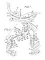
- Figure 1 is an elevational view of a chair made according to the present invention.
- Figure 2 is an enlarged exploded view of the drive mechanism and track system, parts being broken away for clarity.
- Figure 3 is a bottom view of the drive mechanism and track system, parts being broken away for clarity.
- Figure 4 is a sectional view taken along line 4-4 of Figure 3.
- Figure 5 is a sectional view taken along line 5-5 of Figure 3.
- Referring to the drawings wherein like numerals indicate like elements there is shown in Figure 1 an adjustable chair generally designated as 10. The
adjustable chair 10 includes aseat portion 12 and abase portion 14.Seat portion 12 has a convexundersurface 22. Optionally,seat portion 12 may include anarm 18. Thearm 18 has a mate (not shown) located on the opposite side ofseat portion 12. Forward and rear lowprofile roller bearings seat portion 12 in a spaced apart relationship which is further described below. These roller bearings have mates (not shown) located on the opposite side ofseat portion 12.Base portion 14 includes an upperconcave surface 20.Legs 16 are affixed to thebase portion 14 so to support thechair 10 above the floor in a conventional manner. Forward and reararcuate tracks convex surface 22 ofbase portion 14. These arcuate tracks are described in greater detail below. Mates (not shown) to these tracks are located on the opposite side ofbase portion 14. -
Seat portion 12 is adapted to be moved in the arcuate path defined by the upperconcave surface 20 of thebase portion 14. The forward and rearlow profile bearings arcuate tracks seat portion 12 along its arcuate path is described in greater detail below. -
Seat portion 12 is constructed in a manner which is well understood by those skilled in the art. Theseat portion 12 includes laterally disposed convex side members (not shown) joined together by a plurality of cross members (not shown). Such a construction is disclosed in U.S. Patent 4,101,168 which is incorporated herein by reference. -
Base portion 14 is also constructed in a manner which is known to those skilled in the art.Base portion 14 includes laterally disposed concave side members (not shown) joined together by a plurality of cross members (not shown). Such a construction is disclosed in U.S. Patent No. 4,101,168 which is incorporated herein by reference. - The
legs 16 are affixed to the underside ofbase portion 14. Alternatively, they may be affixed to either the lateral concave side members or to the cross members. - Referring to Figure 2, a
seat cross memDer 32 has arecess 34. A pair ofbracket mounting holes 40 are disposeo throughcross member 32. The pair ofholes 40 are locatea adjacent an end ofrecess 34. Theholes 40 are spaced apart perpendicular to the longitudinal axis ofrecess 34. An internally threaded anchor is disposed within eachhole 40. An actuatorbracket mounting pad 36 having a pair of holes disposed therethrough is placea in face contact withcross member 32.Mounting pad 36 is mace of a plastic material and acts as a sound deadening and vibration reducing device. The holes throughmounting pad 36 coincide withholes 40 ofcross member 32. Anactuator bracket 38 is located in face contact withmounting pad 36.Bracket 38 includes a pair of holes which coincide to the holes ofpad 36 and toholes 40 ofcross member 32.Bracket 38 is generally U-shaped in cross section and has a tongue located at the terminal end of the base of thebracket 38.Bracket arms 42 extends down at right angles from the base portion ofbracket 38. Eachbracket arm 42 includes ahole 44. Theholes 44 of eachbracket arm 42 are coaxial.Bracket 38 andpad 36 are secured to crossmember 32 by a pair ofbolts 46.Bolts 46 are placed through the holes ofbracket 38,pad 36 and are threadedly engaged into the anchors located inholes 40 ofcross member 32.Washers 48 are placed aroundbolts 46 prior to the insertion of those bolts into the holes ofbracket 38. - An
actuator mounting arm 50 has ahole 52 disposed therethrough. Mountingarm 50 is inserted betweenarms 42 ofbracket 38. Thehole 52 of mountingarm 50 is aligned withholes 44 ofarms 42 ofbracket 38. Mountingbushings 54 having coaxial bushing holes are inserted intoholes 44 ofarms 42 ofbracket 38. A mountingpin 56 is then inserted through the bushing holes ofbushings 54. The mountingpin 56 is then secured in place by acotter pin 60. This assembly acts as a pivot which is explained later. - The mounting
arm 50 is affixed to atransmission 66. The axis ofhole 52 is parallel totransmission 66.Transmission 66 is coupled perpendicularly to amotor 62 and a threadedshaft 68.Transmission 66 is any transmission capable of translating rotary motion ofmotor 62 into rotary motion ofshaft 68.Motor 62 is parallel to and spaced apart fromshaft 68.Motor 62 is connected to an external source of electrical power throughelectrical lines 64.Motor 62 is any standard electrical motor capable of movingseat portion 12 with a load.Motor 62 is well-known in the art. - When
motor 62 is actuated by an external command signal, such a signal can be supplied through a switch which is well known in the art. The rotary motion ofmotor 62 is communicated throughtransmission 66 to rotary motion ofshaft 68. Anacme nut 70 is threadingly engaged onshaft 68.Acme nut 70 travels along the longitudinal axis ofshaft 68, Theacme nut 70 is indirectly coupled to thebase portion 14, as described below. Thus, asacme nut 70 travelsseat portion 12 moves in its arcuate path.Acme nut 70 includes a pair of internally threaded holes diametrically opposed through theacme nut 70. A noise dampening preloadedspring 74 straddlesacme nut 70.Spring 74 includes a pair of arms havingcoaxial holes 76 and outwardly extending flanges. The flanges engage the terminal ends ofarms 80. The flanges preventspring 74 from rotating about mountingbolts 84.Holes 76 are aligned withholes 72 ofacme nut 70.Spring 74 also includes a tongue. The tongue ofspring 74 is integral with the base ofspring 74. The tongue is inclined toward theacme nut 70. The free end of the tongue is in engagement with theacme nut 70. See Figure 4.Spring 74 eliminates noise whenseat portion 12 moves through the no load mode. - A
base cross member 92 has a pair of bracket mounting holes 90.Bracket mounting holes 90 are disposed throughcross member 92 and are perpendicular to the longitudinal axis ofcross member 92. An internally threaded anchor is secured within each of theholes 90. Abracket mounting pad 88 having a pair of holes therethrough is in face contact withcross member 92. The holes ofpad 88 are in alignment with theholes 90 ofcross member 92.Pad 88 is a vibration dampening member which is made of plastic. Abracket 78 is generally U-shaped having a tongue extending from a base portion ofbracket 78.Bracket 78 has a pair of holes disposed therethrough. The holes ofbracket 78 are aligned with the holes inpad 88 and the holes throughcross member 92.Bracket 98 has a pair ofarms 80 which extend upwardly at a 90° angle from the base ofbracket 78. Eacharm 80 has ahole 82 disposed therethrough. Theholes 82 of eacharm 80 are coaxial with one another. Thearms 80 ofbracket 78 straddle thespring 74.Bracket 78, andspring 74 are coupled toacme nut 70 by the insertion of mountingbolts 84. Mountingbolts 84 are placed throughholes 82 of mountingbracket 78, holes 76 ofspring 74 and are threadingly engaged into theholes 72 ofacme nut 70. Awasher 68 is placed between the head ofbolt 84 and thehole 82 ofbracket 78.Bracket 78 andpad 88 are secured to crossmember 92 by the use of bolts which extend through the holes ofbracket 78,pad 82 and threadingly engage the anchors secured withinholes 90 ofcross member 92. This assembly acts as a pivot between theshaft 68 andbase portion 14. - In operation,
motor 62 rotatesshaft 68 throughtransmission 66. In turn,acme nut 70 may travel either towards or away fromtransmission 66. Asacme nut 70 approaches the terminal ends ofshaft 68, limit switches (not shown) terminate the rotation ofmotor 62. Thus,acme nut 70 is prevented from turning off the free end ofshaft 68 or stripping its internal threads by engagement withtransmission 66. The limit switches are conventional and well- known in the art as is the circuitry associated with the limit switches which terminate the rotation ofreversible motor 62. Furthermore,motor 62,transmission 66 andshaft 68 are pivotable aboutpin 56. The pivotable movement ofmotor 62,transmission 66 andshaft 68 is unimpeded bycross member 32 because of therecess 34. See Figure 3. Thus allowing this assembly to compactly fit withinchair 10. - Laterally adjacent the ends of
recess 34 is a pair of screw holes. Aroller bearing pad 94 having a pair of holes disposed therethrough is in face contact with thecross member 32. The holes throughpad 94 are aligned with the holes inmember 32. See Figure 3. Aroller bearing bracket 96 having a pair of holes through a base portion of thebracket 96 is in face contact withpad 94. The holes inbracket 96 are in alignment with the holes ofpad 94.Bracket 96 has a pair of semicircular arms which extend from the base portion ofbracket 96 at a 90° angle therefrom. Eacharm 98 has ahole 100 disposed therethrough. Theholes 100 are coaxial with one another.Screws 106 extend through the holes of the base portion ofbracket 96, the holes ofpad 94 and are engaged withcross member 32 at the holes therein.Screws 106 secure theroller bracket 96 andpad 94 to thecross member 32. Aroller bearing 102 has ahole 104 coaxial therewith.Roller bearing 102 is inserted betweenarms 98 ofbracket 96. Theholes 100 ofbracket arms 96 are coaxially aligned withhole 104 ofroller bearing 102. Aroller bearing pin 108 is inserted throughhole 100,hole 104 and exits hole 100 of thebracket 96.Pin 108 is secured therethrough by aroller bearing cap 110. Furthermore, the roller bearings assemblies (brackets 96 and bearing 102) are low profile. Thus, a gap spacing between theseat portion 12 andbase portion 14 is minimized so to prevent human body portions from being pinched therebetween. -
Roller bearing 102 is in rolling engagement with a track means. Track means includes atrack portion 112.Track portion 112 is in face contact with avibration dampening pad 114.Pad 114 is located belowtrack 112. A arcuatebase side member 116 is located belowpad 114.Track 112 andpad 114 are secured toside member 116. Thebase side member 116 can be the laterally disposed concave side members previously described or a separate member affixed to the laterally disposed concave side members.Pad 114 is made of a plastic material. There are at least four roller bearing and track assemblies located on the adjustable chair.Roller bearinqs 102 allowseat portion 12 to move in an arcuate path defined by thebase portion 14.
Claims (13)
Priority Applications (1)
| Application Number | Priority Date | Filing Date | Title |
|---|---|---|---|
| AT86304642T ATE48937T1 (en) | 1985-09-13 | 1986-06-16 | ADJUSTABLE CHAIR. |
Applications Claiming Priority (4)
| Application Number | Priority Date | Filing Date | Title |
|---|---|---|---|
| US77585385A | 1985-09-13 | 1985-09-13 | |
| US06/841,039 US4678231A (en) | 1985-09-13 | 1986-03-17 | Adjustable chair |
| US841039 | 1986-03-17 | ||
| US775853 | 1996-12-31 |
Publications (3)
| Publication Number | Publication Date |
|---|---|
| EP0217488A2 true EP0217488A2 (en) | 1987-04-08 |
| EP0217488A3 EP0217488A3 (en) | 1987-09-30 |
| EP0217488B1 EP0217488B1 (en) | 1989-12-27 |
Family
ID=27119118
Family Applications (1)
| Application Number | Title | Priority Date | Filing Date |
|---|---|---|---|
| EP86304642A Expired EP0217488B1 (en) | 1985-09-13 | 1986-06-16 | Adjustable chair |
Country Status (4)
| Country | Link |
|---|---|
| US (1) | US4678231A (en) |
| EP (1) | EP0217488B1 (en) |
| CA (1) | CA1242379A (en) |
| DE (1) | DE3667746D1 (en) |
Cited By (1)
| Publication number | Priority date | Publication date | Assignee | Title |
|---|---|---|---|---|
| EP2142048B1 (en) * | 2007-04-26 | 2022-08-24 | DewertOkin Technology Group Co., Ltd. | Adjustable chair |
Families Citing this family (7)
| Publication number | Priority date | Publication date | Assignee | Title |
|---|---|---|---|---|
| NO163041C (en) * | 1987-12-08 | 1990-03-28 | Ring Mekanikk As | CHAIR WITH ADJUSTABLE BACK. |
| US5078357A (en) * | 1990-10-16 | 1992-01-07 | Medical Resource Companies Of America | Electric seat lift |
| US6003891A (en) * | 1996-11-12 | 1999-12-21 | Invacare Corporation | Tilt wheelchair with center of gravity compensation |
| US6055877A (en) * | 1998-06-12 | 2000-05-02 | Buehler Products, Inc. | Power seat track motor assembly |
| US7063383B2 (en) * | 2004-10-18 | 2006-06-20 | Shang Neng Wu | Sliding assembly of dynamic mechanism of a massage chair |
| US10500434B2 (en) * | 2015-02-16 | 2019-12-10 | Kuang Yu Metal Working Co., Ltd. | Exercising device and operating method thereof |
| DE102016225835A1 (en) * | 2016-09-21 | 2018-03-22 | Adient Luxembourg Holding S.a.r.l. | ADJUSTMENT DEVICE FOR A VEHICLE SEAT, AND METHOD FOR MOUNTING AN ADJUSTMENT DEVICE |
Family Cites Families (16)
| Publication number | Priority date | Publication date | Assignee | Title |
|---|---|---|---|---|
| US3232575A (en) * | 1966-02-01 | Powered mechanism for positionable ohairs | ||
| US661208A (en) * | 1900-05-07 | 1900-11-06 | Ernest J S Davis | Thill-coupling. |
| US2129124A (en) * | 1933-09-14 | 1938-09-06 | Gen Motors Corp | Transmission mount |
| US2586044A (en) * | 1948-12-06 | 1952-02-19 | John W Gasser | Means for taking up slack in lead screw devices |
| US2686009A (en) * | 1950-08-19 | 1954-08-10 | Bird & Son | Railroad tie pad |
| US2839124A (en) * | 1956-01-16 | 1958-06-17 | Houdaille Industries Inc | Multi-motion seat adjuster with multiple drive motors |
| US3193236A (en) * | 1962-02-12 | 1965-07-06 | Lord Mfg Co | Damped chassis |
| US3640140A (en) * | 1969-06-02 | 1972-02-08 | Res Engineering Co | Actuator |
| US3588170A (en) * | 1969-07-03 | 1971-06-28 | La Z Boy Chair Co | Motor-operated reclining chair |
| US3804460A (en) * | 1972-05-30 | 1974-04-16 | Pelton & Crane Co | Power operated treatment chair |
| US3858452A (en) * | 1973-07-09 | 1975-01-07 | Vemco Products Inc | Emergency release for screw drive operator traveler assembly |
| US4046241A (en) * | 1976-03-24 | 1977-09-06 | Essex Group, Inc. | Over-ride mechanism for screw drive actuator |
| US4101168A (en) * | 1976-12-15 | 1978-07-18 | Contour Chair-Lounge Co., Inc. | Adjustable chair |
| US4210033A (en) * | 1977-07-19 | 1980-07-01 | Kerk Motion Products, Inc. | Anti-backlash nut |
| US4173372A (en) * | 1977-10-11 | 1979-11-06 | Gary Reynolds | Dental chair |
| JPS5854263Y2 (en) * | 1977-10-12 | 1983-12-10 | 日産自動車株式会社 | position storage device |
-
1986
- 1986-03-17 US US06/841,039 patent/US4678231A/en not_active Expired - Fee Related
- 1986-06-12 CA CA000511380A patent/CA1242379A/en not_active Expired
- 1986-06-16 DE DE8686304642T patent/DE3667746D1/en not_active Expired - Lifetime
- 1986-06-16 EP EP86304642A patent/EP0217488B1/en not_active Expired
Cited By (1)
| Publication number | Priority date | Publication date | Assignee | Title |
|---|---|---|---|---|
| EP2142048B1 (en) * | 2007-04-26 | 2022-08-24 | DewertOkin Technology Group Co., Ltd. | Adjustable chair |
Also Published As
| Publication number | Publication date |
|---|---|
| EP0217488A3 (en) | 1987-09-30 |
| CA1242379A (en) | 1988-09-27 |
| DE3667746D1 (en) | 1990-02-01 |
| EP0217488B1 (en) | 1989-12-27 |
| US4678231A (en) | 1987-07-07 |
Similar Documents
| Publication | Publication Date | Title |
|---|---|---|
| US6991609B2 (en) | Massage assembly and massage machine incorporating same | |
| US4678231A (en) | Adjustable chair | |
| US4259949A (en) | Anti-friction screw and nut assembly | |
| JP4920166B2 (en) | Furniture drive formed as a double drive | |
| EP0350759A2 (en) | Motor-operated tilt steering device | |
| JP3420773B2 (en) | Drive mechanism for adjusting parts in sitting and lying furniture | |
| JPH10102885A (en) | Preventive structure against falling of hanging door | |
| US7004916B2 (en) | Massaging device for chairs with guide rail and carriage assembly | |
| FR2786977B1 (en) | MOWER COMPRISING A CENTRALIZED DEVICE FOR ADJUSTING THE LIGHTNING FORCE EXERCISED ON THE HARVESTING MECHANISM | |
| FI84552C (en) | Swing mechanism with arresting | |
| US5497982A (en) | Universal ski holding device | |
| US6814710B1 (en) | Massaging device for chairs | |
| US4715361A (en) | Passive mobilizer | |
| JPH0420661Y2 (en) | ||
| KR20060028964A (en) | Variable Limit Switch Assemblies | |
| JPH0710997Y2 (en) | Electric tilt steering device | |
| CA2068757C (en) | Track switch | |
| JPH0524580Y2 (en) | ||
| JPH0426099Y2 (en) | ||
| US3673874A (en) | Reciprocating linear actuator | |
| JPH0326029Y2 (en) | ||
| JP3635770B2 (en) | Linear reciprocating guide device | |
| JPS6422641U (en) | ||
| EP1372568A1 (en) | Improved massaging device for chairs | |
| JPH067969Y2 (en) | Seat lifter |
Legal Events
| Date | Code | Title | Description |
|---|---|---|---|
| PUAI | Public reference made under article 153(3) epc to a published international application that has entered the european phase |
Free format text: ORIGINAL CODE: 0009012 |
|
| 17P | Request for examination filed |
Effective date: 19860625 |
|
| AK | Designated contracting states |
Kind code of ref document: A2 Designated state(s): AT BE CH DE FR GB IT LI LU NL SE |
|
| PUAL | Search report despatched |
Free format text: ORIGINAL CODE: 0009013 |
|
| AK | Designated contracting states |
Kind code of ref document: A3 Designated state(s): AT BE CH DE FR GB IT LI LU NL SE |
|
| 17Q | First examination report despatched |
Effective date: 19881025 |
|
| GRAA | (expected) grant |
Free format text: ORIGINAL CODE: 0009210 |
|
| RAP1 | Party data changed (applicant data changed or rights of an application transferred) |
Owner name: CONTOUR CHAIR-LOUNGE CO., INC. |
|
| AK | Designated contracting states |
Kind code of ref document: B1 Designated state(s): AT BE CH DE FR GB IT LI LU NL SE |
|
| REF | Corresponds to: |
Ref document number: 48937 Country of ref document: AT Date of ref document: 19900115 Kind code of ref document: T |
|
| ITF | It: translation for a ep patent filed | ||
| REF | Corresponds to: |
Ref document number: 3667746 Country of ref document: DE Date of ref document: 19900201 |
|
| ET | Fr: translation filed | ||
| PLBE | No opposition filed within time limit |
Free format text: ORIGINAL CODE: 0009261 |
|
| STAA | Information on the status of an ep patent application or granted ep patent |
Free format text: STATUS: NO OPPOSITION FILED WITHIN TIME LIMIT |
|
| 26N | No opposition filed | ||
| PGFP | Annual fee paid to national office [announced via postgrant information from national office to epo] |
Ref country code: GB Payment date: 19910610 Year of fee payment: 6 |
|
| PGFP | Annual fee paid to national office [announced via postgrant information from national office to epo] |
Ref country code: AT Payment date: 19910612 Year of fee payment: 6 |
|
| PGFP | Annual fee paid to national office [announced via postgrant information from national office to epo] |
Ref country code: SE Payment date: 19910614 Year of fee payment: 6 |
|
| PGFP | Annual fee paid to national office [announced via postgrant information from national office to epo] |
Ref country code: FR Payment date: 19910619 Year of fee payment: 6 |
|
| PGFP | Annual fee paid to national office [announced via postgrant information from national office to epo] |
Ref country code: LU Payment date: 19910620 Year of fee payment: 6 |
|
| PGFP | Annual fee paid to national office [announced via postgrant information from national office to epo] |
Ref country code: CH Payment date: 19910627 Year of fee payment: 6 |
|
| ITTA | It: last paid annual fee | ||
| PGFP | Annual fee paid to national office [announced via postgrant information from national office to epo] |
Ref country code: NL Payment date: 19910630 Year of fee payment: 6 |
|
| PGFP | Annual fee paid to national office [announced via postgrant information from national office to epo] |
Ref country code: DE Payment date: 19910723 Year of fee payment: 6 |
|
| PGFP | Annual fee paid to national office [announced via postgrant information from national office to epo] |
Ref country code: BE Payment date: 19910806 Year of fee payment: 6 |
|
| EPTA | Lu: last paid annual fee | ||
| PG25 | Lapsed in a contracting state [announced via postgrant information from national office to epo] |
Ref country code: LU Free format text: LAPSE BECAUSE OF NON-PAYMENT OF DUE FEES Effective date: 19920616 Ref country code: GB Effective date: 19920616 Ref country code: AT Effective date: 19920616 |
|
| PG25 | Lapsed in a contracting state [announced via postgrant information from national office to epo] |
Ref country code: SE Effective date: 19920617 |
|
| PG25 | Lapsed in a contracting state [announced via postgrant information from national office to epo] |
Ref country code: LI Effective date: 19920630 Ref country code: CH Effective date: 19920630 Ref country code: BE Effective date: 19920630 |
|
| BERE | Be: lapsed |
Owner name: CONTOUR CHAIR-LOUNGE CO. INC. Effective date: 19920630 |
|
| PG25 | Lapsed in a contracting state [announced via postgrant information from national office to epo] |
Ref country code: NL Effective date: 19930101 |
|
| GBPC | Gb: european patent ceased through non-payment of renewal fee |
Effective date: 19920616 |
|
| NLV4 | Nl: lapsed or anulled due to non-payment of the annual fee | ||
| PG25 | Lapsed in a contracting state [announced via postgrant information from national office to epo] |
Ref country code: FR Effective date: 19930226 |
|
| REG | Reference to a national code |
Ref country code: CH Ref legal event code: PL |
|
| PG25 | Lapsed in a contracting state [announced via postgrant information from national office to epo] |
Ref country code: DE Effective date: 19930302 |
|
| REG | Reference to a national code |
Ref country code: FR Ref legal event code: ST |
|
| EUG | Se: european patent has lapsed |
Ref document number: 86304642.1 Effective date: 19930109 |
|
| PG25 | Lapsed in a contracting state [announced via postgrant information from national office to epo] |
Ref country code: IT Free format text: LAPSE BECAUSE OF NON-PAYMENT OF DUE FEES;WARNING: LAPSES OF ITALIAN PATENTS WITH EFFECTIVE DATE BEFORE 2007 MAY HAVE OCCURRED AT ANY TIME BEFORE 2007. THE CORRECT EFFECTIVE DATE MAY BE DIFFERENT FROM THE ONE RECORDED. Effective date: 20050616 |