EP2140275B1 - Piezo dispensing of a diagnostic liquid into microfluidic devices - Google Patents
Piezo dispensing of a diagnostic liquid into microfluidic devices Download PDFInfo
- Publication number
- EP2140275B1 EP2140275B1 EP08732211.1A EP08732211A EP2140275B1 EP 2140275 B1 EP2140275 B1 EP 2140275B1 EP 08732211 A EP08732211 A EP 08732211A EP 2140275 B1 EP2140275 B1 EP 2140275B1
- Authority
- EP
- European Patent Office
- Prior art keywords
- sample
- capillary
- reagent
- droplets
- liquid
- Prior art date
- Legal status (The legal status is an assumption and is not a legal conclusion. Google has not performed a legal analysis and makes no representation as to the accuracy of the status listed.)
- Active
Links
Images
Classifications
-
- B—PERFORMING OPERATIONS; TRANSPORTING
- B01—PHYSICAL OR CHEMICAL PROCESSES OR APPARATUS IN GENERAL
- B01L—CHEMICAL OR PHYSICAL LABORATORY APPARATUS FOR GENERAL USE
- B01L3/00—Containers or dishes for laboratory use, e.g. laboratory glassware; Droppers
- B01L3/50—Containers for the purpose of retaining a material to be analysed, e.g. test tubes
- B01L3/502—Containers for the purpose of retaining a material to be analysed, e.g. test tubes with fluid transport, e.g. in multi-compartment structures
- B01L3/5027—Containers for the purpose of retaining a material to be analysed, e.g. test tubes with fluid transport, e.g. in multi-compartment structures by integrated microfluidic structures, i.e. dimensions of channels and chambers are such that surface tension forces are important, e.g. lab-on-a-chip
- B01L3/502738—Containers for the purpose of retaining a material to be analysed, e.g. test tubes with fluid transport, e.g. in multi-compartment structures by integrated microfluidic structures, i.e. dimensions of channels and chambers are such that surface tension forces are important, e.g. lab-on-a-chip characterised by integrated valves
-
- B—PERFORMING OPERATIONS; TRANSPORTING
- B01—PHYSICAL OR CHEMICAL PROCESSES OR APPARATUS IN GENERAL
- B01L—CHEMICAL OR PHYSICAL LABORATORY APPARATUS FOR GENERAL USE
- B01L3/00—Containers or dishes for laboratory use, e.g. laboratory glassware; Droppers
- B01L3/50—Containers for the purpose of retaining a material to be analysed, e.g. test tubes
- B01L3/502—Containers for the purpose of retaining a material to be analysed, e.g. test tubes with fluid transport, e.g. in multi-compartment structures
- B01L3/5027—Containers for the purpose of retaining a material to be analysed, e.g. test tubes with fluid transport, e.g. in multi-compartment structures by integrated microfluidic structures, i.e. dimensions of channels and chambers are such that surface tension forces are important, e.g. lab-on-a-chip
- B01L3/50273—Containers for the purpose of retaining a material to be analysed, e.g. test tubes with fluid transport, e.g. in multi-compartment structures by integrated microfluidic structures, i.e. dimensions of channels and chambers are such that surface tension forces are important, e.g. lab-on-a-chip characterised by the means or forces applied to move the fluids
-
- B—PERFORMING OPERATIONS; TRANSPORTING
- B01—PHYSICAL OR CHEMICAL PROCESSES OR APPARATUS IN GENERAL
- B01L—CHEMICAL OR PHYSICAL LABORATORY APPARATUS FOR GENERAL USE
- B01L2200/00—Solutions for specific problems relating to chemical or physical laboratory apparatus
- B01L2200/06—Fluid handling related problems
- B01L2200/0621—Control of the sequence of chambers filled or emptied
-
- B—PERFORMING OPERATIONS; TRANSPORTING
- B01—PHYSICAL OR CHEMICAL PROCESSES OR APPARATUS IN GENERAL
- B01L—CHEMICAL OR PHYSICAL LABORATORY APPARATUS FOR GENERAL USE
- B01L2300/00—Additional constructional details
- B01L2300/06—Auxiliary integrated devices, integrated components
- B01L2300/0627—Sensor or part of a sensor is integrated
- B01L2300/0636—Integrated biosensor, microarrays
-
- B—PERFORMING OPERATIONS; TRANSPORTING
- B01—PHYSICAL OR CHEMICAL PROCESSES OR APPARATUS IN GENERAL
- B01L—CHEMICAL OR PHYSICAL LABORATORY APPARATUS FOR GENERAL USE
- B01L2300/00—Additional constructional details
- B01L2300/08—Geometry, shape and general structure
- B01L2300/0809—Geometry, shape and general structure rectangular shaped
- B01L2300/0825—Test strips
-
- B—PERFORMING OPERATIONS; TRANSPORTING
- B01—PHYSICAL OR CHEMICAL PROCESSES OR APPARATUS IN GENERAL
- B01L—CHEMICAL OR PHYSICAL LABORATORY APPARATUS FOR GENERAL USE
- B01L2400/00—Moving or stopping fluids
- B01L2400/04—Moving fluids with specific forces or mechanical means
- B01L2400/0403—Moving fluids with specific forces or mechanical means specific forces
- B01L2400/0406—Moving fluids with specific forces or mechanical means specific forces capillary forces
-
- B—PERFORMING OPERATIONS; TRANSPORTING
- B01—PHYSICAL OR CHEMICAL PROCESSES OR APPARATUS IN GENERAL
- B01L—CHEMICAL OR PHYSICAL LABORATORY APPARATUS FOR GENERAL USE
- B01L2400/00—Moving or stopping fluids
- B01L2400/06—Valves, specific forms thereof
- B01L2400/0688—Valves, specific forms thereof surface tension valves, capillary stop, capillary break
-
- B—PERFORMING OPERATIONS; TRANSPORTING
- B01—PHYSICAL OR CHEMICAL PROCESSES OR APPARATUS IN GENERAL
- B01L—CHEMICAL OR PHYSICAL LABORATORY APPARATUS FOR GENERAL USE
- B01L2400/00—Moving or stopping fluids
- B01L2400/08—Regulating or influencing the flow resistance
- B01L2400/084—Passive control of flow resistance
- B01L2400/086—Passive control of flow resistance using baffles or other fixed flow obstructions
-
- B—PERFORMING OPERATIONS; TRANSPORTING
- B01—PHYSICAL OR CHEMICAL PROCESSES OR APPARATUS IN GENERAL
- B01L—CHEMICAL OR PHYSICAL LABORATORY APPARATUS FOR GENERAL USE
- B01L3/00—Containers or dishes for laboratory use, e.g. laboratory glassware; Droppers
- B01L3/02—Burettes; Pipettes
- B01L3/0241—Drop counters; Drop formers
- B01L3/0268—Drop counters; Drop formers using pulse dispensing or spraying, eg. inkjet type, piezo actuated ejection of droplets from capillaries
-
- Y—GENERAL TAGGING OF NEW TECHNOLOGICAL DEVELOPMENTS; GENERAL TAGGING OF CROSS-SECTIONAL TECHNOLOGIES SPANNING OVER SEVERAL SECTIONS OF THE IPC; TECHNICAL SUBJECTS COVERED BY FORMER USPC CROSS-REFERENCE ART COLLECTIONS [XRACs] AND DIGESTS
- Y10—TECHNICAL SUBJECTS COVERED BY FORMER USPC
- Y10T—TECHNICAL SUBJECTS COVERED BY FORMER US CLASSIFICATION
- Y10T436/00—Chemistry: analytical and immunological testing
- Y10T436/11—Automated chemical analysis
- Y10T436/117497—Automated chemical analysis with a continuously flowing sample or carrier stream
- Y10T436/118339—Automated chemical analysis with a continuously flowing sample or carrier stream with formation of a segmented stream
Definitions
- This invention relates to reagents and instruments used to measure the quantity of analytes in biological samples by the reaction of the analytes with reagents to produce a detectable response.
- a sample liquid is applied to a surface containing reagents that react with the analyte.
- the reagents produce a detectable response that is measured and related to the amount of the analyte.
- the surface usually will be either hydrophilic or hydrophobic in nature, e.g. filter paper compared to polystyrene.
- a strip containing unreacted reagents is dipped, i.e. fully immersed in a liquid sample, and the reaction between the analyte in the sample and the reagents is measured, usually by optical methods.
- the unreacted reagents themselves may be water soluble or insoluble. They are deposited or immobilized and dried in a porous substrate. The substrate is attached or placed onto the supporting surface. Additionally, a liquid with or without reagents can be used during an assay.
- the liquid reagents can be applied to the surfaces of substrates already containing dried reagents, before, after or during the reaction with the analyte, typically being added after a sample has been applied.
- the volume of samples and reagents should be as small as possible for obvious reasons relating to cost and convenience. What is less obvious is that it is often difficult to obtain a uniform and accurate response when applying small amounts of liquid reagents or biological samples to surfaces containing reagents.
- the response of the analyte with reagents is smaller than the reaction area in smaller and less analyte is present.
- the substrate can be used to amplify the reaction response.
- Thin films e.g. membranes, can be immobilized with affinity reagents to allow capturing and concentration of reactants in read zones.
- Directing flow of liquids in a desired direction e.g. laterally rather than vertically, can increase efficiency by increasing the number of fluidic exchanges between the liquid sample or reagent and the reaction zone. Each exchange allows further reaction of the analyte to occur, thereby amplifying the signal.
- Modification of the surface of the substrate allows reagents to be isolated in the reaction zone. Further, the nature of the surface itself can be used to increase the reactivity of the analyte, for example by increasing solubilization of reagents or to favor reactions with reagents on the surface.
- sample and reagent liquids when dispensed spread rapidly across hydrophilic substrates and are repelled by hydrophobic substrates.
- the contact between the dispensed liquid and the reagents on the surface is made by direct dispensing onto the reacted or partially reacted area.
- substrates are relatively hydrophobic, the dispensed liquid will form beads on the surface of the substrate that attempt to minimize their contact with the surface and therefore they do not spread uniformly over the reagent.
- Another difficulty associated with dispensing liquids is that the dried reagents may be either water soluble or water insoluble in nature.
- the insoluble dry reagents may not be readily accessible to the liquid samples, or soluble reagents may be dissolved and move with the liquid on the substrate.
- the reagents ideally should contact the sample uniformly, since the measurable response of the reagents to the sample, e.g. color development, should be uniform in order to obtain an accurate reading of the quantity of the analyte in the sample.
- Another problem related to obtaining good contact between a dispensed liquid and a reagent on a surface is related to the physical nature of the samples. They vary in their physical properties such as surface tension, viscosity, total solids content, particle size and adhesion. Therefore, they are not easily deposited in consistent volumes uniformly over the reagent-covered substrate. Also, as the amount of the liquid sample is reduced, it becomes increasingly difficult to apply a consistent amount of a sample having varying properties to the reagents. In contrast, ink-jet printing and the like rely on liquids developed for such uses and having consistent physical properties.
- Deposition of droplets of liquid is a familiar operation.
- Examples include the ink jet-printer, either piezoelectric or bubble actuated, which forms print from the controlled deposition of multiple small droplets of about 2 to 300 ⁇ m diameter (typically 50 ⁇ m) containing from a few femtoliters to tens of nanoliters.
- Other methods of depositing small droplets have been proposed, which generally employ piezoelectric principles to create droplets, although they differ from typical ink-jet printers. Examples are found in U.S. Patents 5,063,396 ; 5,518,179 ; 6,394,363 ; and 6,656,432 .
- Deposition of larger droplets (3-100 ⁇ L) through a syringe type pipette is known to be reproducible in diagnostic systems. This corresponds to single droplet diameters of about 2 to 6 mm.
- a commercial example of such pipette systems is the CLINITEK ALTAS® urinalysis analyzer.
- the droplet size can be greater or less than the nozzle size depending on the nozzle shape, pump type and pressures applied.
- Smaller droplets of a few femtoliters to tens of nanoliters, can also be a problem when deposited on a substrate that is too hydrophobic as they lack the volume to completely cover the surface area and will randomly aggregate in non-uniform patterns. Small drops also allow open spaces for migration of water-soluble reagents. These tiny droplets are also prone to evaporation of liquids and to formation of aerosols, which are considered to be biohazardous if comprised of urine or blood specimens. Thus, if a liquid is to be deposited as droplets on test pads, rather than dipping the pads in the sample, improvements were needed.
- results may be read using one of several methods. Optical methods are commonly used, which rely on spectroscopic signals to produce responses. Results must be reproducible to be useful. Optical measurements are affected by the reagent area viewed and by the time allowed for the dispensed liquids and reagents to react. Formation of non-uniform areas within the field of view and changes in the amount of reaction time cause increased errors. For example, a measurement made of a sample or reagent which has spread non-uniformly across the substrate gives a different result each time it is read.
- Depositing of small droplets was done either by nozzles having many small openings or by single nozzles, which could be moved relative to the reagent-carrying substrate, or vice versa, to cover the desired area.
- the reaction of liquid samples with reagents on the substrate could be read as an average of the area covered by the sample or preferably by scanning the reaction area one spot at a time and averaging the results.
- Adding biological samples and associated liquids to microfluidic devices used for analysis of biological samples may be done with various techniques. Very small samples of blood, urine and the like are introduced into such devices, where they come into contact with reagents capable of indicating the presence and quantity of analytes found in the sample.
- the problem relates to the variability inherent in these designs.
- the variability in the surface coating can cause liquids to creep over capillary stops or around reagent areas. This causes variations in the timing of liquid movements and the volumes reacted.
- less experienced users can apply incorrect amounts of samples or reagents.
- the internal dimensions of these microfluidic devices can differ from one chip to another when they are made in large quantities by low cost methods. The present inventors have found that such problems can be overcome, making significant improvements in the accuracy and repeatability of results.
- the invention is an improved method of assaying for the amount of an analyte contained in a biological fluid, as described in claim 1.
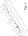
- Figure 1 shows the microfluidic device of Example 1.
- “Spectroscopic image” refers to a detailed view of the optical response of a reagent-containing area to a biological sample deposited on the reagent-containing area, for example using a change in color, reflectance, transmission or absorbance or others such as Raman, fluorescence, chemiluminescence, phosphorescence, or electrochemical impedance spectroscopy, which enables examination of sub-units of the entire reagent-containing area.
- the image can be multi-dimensional with position(i.e. x-y) being added to the optical response.
- Hydrophilic surfaces are those that have a less than 90° contact angle between the surface and a drop of water placed thereon.
- Hydrophilic surfaces are those that have a 90° or larger contact angle between the surface and a drop of water placed thereon.
- the present invention provides improved control of reactions occurring within porous substrates ("pads"), which contain dried reagents and are located within microfluidic devices.
- the reactions result from the interaction between a sample liquid and a reagent-containing pad.
- the liquid When a liquid sample containing an unknown amount of an analyte contacts a reagent-containing pad, the liquid must dissolve the reagent so that the reaction with the analyte can occur, which produces a detectable result e.g. a distinctive optical signal, such as color, which is detected by spectrographic means.
- a detectable result e.g. a distinctive optical signal, such as color, which is detected by spectrographic means.
- the speed at which the reaction occurs and the extent to which the result is detectable is affected by a number of factors. Such factors include the accessibility of the reagent, its solubility in the liquid, and the relative amounts of the reagent and the liquid in the region in which the liquid is placed.
- the uniform application of liquids to a porous pad is important if consistent and accurate results are to be obtained.
- the characteristics of the pad e.g.
- the pad characteristics not only affect the volume of liquid absorbed, but also the solubilizing and surface interactions of reagents dried onto the pad. They also affect the direction in which liquids flow and the ability to fix reagents in a specific location. For example, pads are often used with the films such as membranes that allow liquids to flow laterally rather than vertically. Thus the number of fluid exchanges that can be done in a defined reaction zone. When the reaction zones contain immobilized bioaffinity molecules, e.g. antibodies and nucleic acids, the capture efficiency is increased by the number of fluid exchanges. In practice, one skilled in the art finds that the physical characteristics of the pad itself, the reagents, and the sample liquid all must be considered in designing a useful assay system.
- the sample In contrast to direct deposition of a sample (and associated liquids) to a reagent-containing pad, in microfluidic devices the sample will be added to an inlet port and then transferred through intervening wells and capillary passageways to a chamber containing a reagent-containing pad. Often a sample is mixed or diluted with another liquid, such as a liquid reagent. The sample can be added to the microfluidic device before, at the same time as the liquid reagent, or after. Single or multiple inlet ports can be used. Although the sample, liquid reagent, and mixtures can flow differently, it is still important to distribute the liquids uniformly.
- the timed application of sample liquids and/or other associated liquids in precise patterns in small increments at specific times into target areas provides improved control of the interaction of the liquids with the reagent-containing pad to provide increased accuracy and uniformity of results.
- reagents are placed in porous substrates or "pads" and the substrates in strip form are dipped into the biological fluid being tested. Although such assays are useful, they are not necessarily as accurate or repeatable as desired. It was previously shown that depositing large sample droplets (i.e. 1-7 ⁇ L to 20.4 ⁇ L) was not as satisfactory as dipping strips in liquid. However, small droplets (i.e. 50 pL to 1 ⁇ L) provided superior results in an array of biological assays.
- a single nozzle is used to dispense a sequence of single droplets onto the reagent-containing substrate. Either the nozzle or the substrate would be moved to provide uniform coverage in the desired area.
- the second type of nozzle used a plate drilled with a series of holes so that multiple sequences of droplets could be dispensed at one time. In either type, the smallest droplet size was considered to about 50 pL, which would be associated with hole diameters of about 45-50 ⁇ m.
- the nozzles could be operated by pressure from various sources. Using piezo actuators was one preferred method of dispensing the small droplets.
- microfluidic devices can be operated by moving a first liquid with a predetermined amount of a second liquid, either to a capillary stop or to introduce a needed amount of the second liquid.
- the method of the invention provides more accurate movement of liquids in the microfluidic device.
- dispensing liquids in known amounts made it possible to control the sequence of liquid movements in a manner that was not previously attainable. This is illustrated in the following example in which a biological sample, (whole blood) was added to a microfluidic device, followed by lysis and wash solutions.
- HbA 1C immunoassay was carried out on a nitrocellulose substrate (5.0 ⁇ m pore), on which was placed two 4mm wide capture bands.
- the first band contained an HbA 1C agglutinator (a mimic of the analyte HbA 1C ; 1mg/mL in PBS, pH 7.4).
- the second band contained a monoclonal anti-FITC antibody (3mg/mL in 0.05 borate, pH 8.5).
- a conjugate for binding the HbA 1C analyte was made which contained blue latex particles attached to BSA labeled with FITC and HbA 1C antibody. Two concentrations were prepared for use in high (8-15% HbA 1C ) and low (3-8% HbA 1C ) concentration assays.
- the BSA-labeled material was attached to blue latex particles (300 nm, 67 ⁇ eq. of COOH/g) at a loading of 30 ⁇ g BSA-FITC-anti- HbA 1C per mg of latex.
- a wash solution of PBS containing 01 % BSA was used for the high range and for the low range a 1:10 dilution of anti-FITC antibody latex conjugate.
- the anti-FITC antibody was prepared with 10 ⁇ g antibody per 1 mg. of blue latex particles.
- the conjugate was dried into glass fiber paper diluted with casein blocking buffer. For the high range the conjugate was diluted in a 1:4 ratio, for the low range a 1:400 dilution was used.
- the HbA 1C was present in a biological sample, in this case blood, it would bind to the conjugate. Then the bound conjugate would not bind to the agglutination band, but would pass to the second band where it would be bound to the anti-FITC antibody. Excess conjugate would be bound by the first band since it would bind to the HbA 1C antibody in the conjugate.
- the amount of HbA 1C in the sample could be determined.
- the nitrocellulose strip containing the two capture bands was placed in a microfluidic device, illustrated in Figure 1 .
- This device has four chambers connected by capillary channels and has a total volume of about 20 ⁇ L.
- the first chamber is the inlet port for the device. It is open to the surroundings.
- Chamber 2 contains the conjugate on a glass fiber paper and supported on microposts.
- the nitrocellulose capture strip is in Chamber 3, the entrance of which contains an array of microposts to distribute the liquids.
- Chamber 4 contains a porous pad used to remove excess liquid from Chamber 3.
- the sample (whole blood) was added to Chamber 1 which determine the volume of the sample. It flows through a capillary and is stopped at the entrance to Chamber 2.
- a lysis solution (Cellytic-M, Sigma Aldrich, St. Louis, MO) was added to force the sample into Chamber 2, where it contacts the conjugate.
- wash liquid was added to Chamber 1 to force the sample and the conjugate through the stop at the entrance of Chamber 3, so that the diluted sample passes over the capture bands on the strip. Color is developed from FITC in the capture bands and read with a CCD camera as the optical detector and then compared by appropriate software with calibration data. Additional liquid is fed into Chamber 1 to move the residual sample into Chamber 4, which contains an absorbent pad.
- Tests were carried out with this microfluidic device in which three methods were used to add liquids to Chamber 1.
- a conventional capillary pipette having an opening of about 0.3 to 2 mm and which dispensed droplets of about 0.3-100 ⁇ L, depending on the fill length, was used to place the sample and other liquids in the inlet port.
- a micro-dispensing head having an opening of about 50 ⁇ m dispensed the sample and liquids in a continuous manner without pause. The same micro-dispensing head also was used intermittently, with intervals in which no liquids were dispensed, and timed to move precisely to overcome the capillary stops.
- % overfill or % underfill refers to a series of tests in which the microfuidic device of Figure 1 was tested and in which it was found that more or less liquid was added than was required for the reaction.
- % non-uniform color refers to the color developed in Chamber 3, which indicates the amount of the conjugate captured and permits calculation of the amount of HbA 1C in the sample.
- Ti of response refers to the minimum time found from experience for liquid to begin flowing from Chamber 2 to Chamber 3 in the microfluidic device.
- the microdispensing head used in the previous example was capable of dispensing droplets of about 100 pL at a rate of 85 drops/millisecond.
- HbA 1C assay described above it was important to provide the proper time for incubation of the sample with the conjugate and the reaction of the sample/conjugate to be completed before washing the assay strip. This requires monitoring of the progress of the sample and controlling the timing of the addition of diluents. It is important to optimizing the assay that the sample and the sample/conjugate be moved at certain speeds. This is possible when the position of the sample and sample/conjugate are continually monitored by and the addition of diluents is controlled accordingly.
- microdispensing was controlled to provide groups of 85 droplets per millisecond with intervals of 0.1 sec.
- Dispensing Method Timing Accuracy Smallest Volume Added Volume Tolerance Large Pipette ⁇ 1 seconds 1.7 ⁇ L 0%
- Microdispensing (continuous) ⁇ 0.5 milliseconds 5.0 nL
- Microdispensing Intensified Groups ⁇ 0.01 milliseconds 100 pL 99.6%
- Timing Accuracy refers to the minimum period of time required to operate the dispensing method.
- Smallest Volume Added refers to the extent to which each dispensing method can be controlled.
- Volume Tolerance refers to the variation in volume from that desired for optimum operation of the microfluidic device.
- the capillaries between chambers have a volume of about 50 nL which is the smallest volume that can be added before the capillary stop at the end of the capillary is triggered.
- the volume tolerance is zero for the large pipette when the smallest volume dispensed is more than 50 nL. Even when using a capillary as a pipette, a volume of 0.3 ⁇ L (300 nL) would still have a zero volume tolerance.
- the smallest group is one drop.
- the drop is dispensed at 85 drops/msec and each drop has a volume of 100 pL.
- the volume then is about 0.1 ⁇ L/msec (8.5 nL/msec).
- This is generally a good operating range. It provides a high volume tolerance and the microfluidic device is reliably fired 99.996% of time.
- a miss-fire or variation in the microfluidic capillary volume can be corrected for by an additional group of droplets.
- the typical operating range is 30 to 150 drops/msec and the drop volumes are from about 30 pL to 1000 nL.
- the dispenser can be stopped electronically, but more drops than one are typically dispensed.
- "Smallest volume added” would be 50 drops of 0.100 nL or 5 nL. This means the volume tolerance is not as high for the device or 80% of time (4 out of 5). Since microfluidic device can operate with capillaries only holding 5 nL, this tolerance is less acceptable than that observed for microdispensing with intensified groups.
Landscapes
- Chemical & Material Sciences (AREA)
- Health & Medical Sciences (AREA)
- Dispersion Chemistry (AREA)
- Analytical Chemistry (AREA)
- General Health & Medical Sciences (AREA)
- Hematology (AREA)
- Clinical Laboratory Science (AREA)
- Chemical Kinetics & Catalysis (AREA)
- Automatic Analysis And Handling Materials Therefor (AREA)
Applications Claiming Priority (2)
| Application Number | Priority Date | Filing Date | Title |
|---|---|---|---|
| US91545007P | 2007-05-02 | 2007-05-02 | |
| PCT/US2008/056983 WO2008137212A1 (en) | 2007-05-02 | 2008-03-14 | Piezo dispensing of a diagnostic liquid into microfluidic devices |
Publications (3)
| Publication Number | Publication Date |
|---|---|
| EP2140275A1 EP2140275A1 (en) | 2010-01-06 |
| EP2140275A4 EP2140275A4 (en) | 2014-11-26 |
| EP2140275B1 true EP2140275B1 (en) | 2017-12-20 |
Family
ID=39943878
Family Applications (1)
| Application Number | Title | Priority Date | Filing Date |
|---|---|---|---|
| EP08732211.1A Active EP2140275B1 (en) | 2007-05-02 | 2008-03-14 | Piezo dispensing of a diagnostic liquid into microfluidic devices |
Country Status (6)
| Country | Link |
|---|---|
| US (1) | US8361782B2 (enExample) |
| EP (1) | EP2140275B1 (enExample) |
| JP (1) | JP5296054B2 (enExample) |
| CN (1) | CN101688875B (enExample) |
| DK (1) | DK2140275T3 (enExample) |
| WO (1) | WO2008137212A1 (enExample) |
Families Citing this family (11)
| Publication number | Priority date | Publication date | Assignee | Title |
|---|---|---|---|---|
| KR100968524B1 (ko) * | 2008-04-11 | 2010-07-08 | 인싸이토 주식회사 | 생체 시료 분석용 마이크로-나노 플루이딕 바이오칩 |
| KR100961874B1 (ko) * | 2010-04-05 | 2010-06-09 | 주식회사 나노엔텍 | 외부동력 없이 유체가 이동하는 유체분석용 칩 |
| KR101208303B1 (ko) | 2010-12-10 | 2012-12-05 | 삼성전기주식회사 | 미세 토출기 및 이의 제조방법 |
| WO2013163549A1 (en) * | 2012-04-26 | 2013-10-31 | The University Of Akron | Flexible tactile sensors and method of making |
| EP3066190B1 (en) * | 2013-11-06 | 2020-12-30 | Becton, Dickinson and Company | Microfluidic devices, and methods of using the same |
| JP6518245B2 (ja) | 2013-11-13 | 2019-05-22 | ベクトン・ディキンソン・アンド・カンパニーBecton, Dickinson And Company | 光学撮像システム及びそれを用いた方法 |
| GB201614150D0 (en) | 2016-08-18 | 2016-10-05 | Univ Oxford Innovation Ltd | Microfluidic arrangements |
| CN108472647B (zh) | 2015-10-16 | 2021-06-29 | 牛津大学科技创新有限公司 | 微流体布置 |
| GB201802819D0 (en) | 2018-02-21 | 2018-04-04 | Univ Oxford Innovation Ltd | Methods and apparatus for manufacturing a microfluidic arrangement, and a microfluidic arrangement |
| EP3569716A1 (en) * | 2018-05-14 | 2019-11-20 | Consejo Superior De Investigaciones Científicas (CSIC) | A method for controlling timing of events in a microfluidic device and a timer microfluidic device |
| CN111057150B (zh) * | 2019-12-30 | 2021-10-29 | 深圳开立生物医疗科技股份有限公司 | 一种乳胶微球及其应用以及糖化血红蛋白检测试剂盒 |
Family Cites Families (31)
| Publication number | Priority date | Publication date | Assignee | Title |
|---|---|---|---|---|
| WO1984002090A1 (en) | 1982-11-20 | 1984-06-07 | Thomas Paterson Whitehead | Dispensing device and recording apparatus |
| US4849340A (en) | 1987-04-03 | 1989-07-18 | Cardiovascular Diagnostics, Inc. | Reaction system element and method for performing prothrombin time assay |
| US5209904A (en) | 1987-12-23 | 1993-05-11 | Abbott Laboratories | Agglutination reaction device utilizing selectively impregnated porous material |
| EP0353591B1 (en) | 1988-08-02 | 1996-04-17 | Abbott Laboratories | Biological sample analyzer |
| JPH02269058A (ja) | 1989-03-14 | 1990-11-02 | Seiko Epson Corp | レーリーモード弾性表面波による液滴ジェット装置 |
| AU2266892A (en) | 1991-06-13 | 1993-01-12 | Abbott Laboratories | Optical imaging for positioning and cell counting |
| ATE131421T1 (de) | 1991-12-04 | 1995-12-15 | The Technology Partnership Plc | Vorrichtung und verfahren zur erzeugung von fluessigkeitstroepfchen |
| CA2276462C (en) | 1996-12-31 | 2007-06-12 | High Throughput Genomics, Inc. | Multiplexed molecular analysis system apparatus and method |
| GB9808182D0 (en) | 1998-04-17 | 1998-06-17 | The Technology Partnership Plc | Liquid projection apparatus |
| CA2289174A1 (en) | 1998-11-09 | 2000-05-09 | Andrew A. Pham | Liquid barriers for assays |
| NL1010833C2 (nl) | 1998-12-17 | 2000-06-20 | Univ Delft Tech | Werkwijze voor het gedoseerd aanbrengen van een vloeistof op een oppervlak. |
| US6245297B1 (en) | 1999-04-16 | 2001-06-12 | Pe Corporation (Ny) | Apparatus and method for transferring small volumes of substances |
| US6656432B1 (en) | 1999-10-22 | 2003-12-02 | Ngk Insulators, Ltd. | Micropipette and dividedly injectable apparatus |
| US7004184B2 (en) | 2000-07-24 | 2006-02-28 | The Reagents Of The University Of Michigan | Compositions and methods for liquid metering in microchannels |
| ATE433574T1 (de) | 2000-08-10 | 2009-06-15 | Biomerieux Bv | Diagnostischer test auf basis von bewegenden tropfen |
| US6833111B2 (en) | 2001-04-13 | 2004-12-21 | Varian, Inc. | Multiple analyte assaying device with a multiple sample introduction system |
| US6485918B1 (en) | 2001-07-02 | 2002-11-26 | Packard Bioscience Corporation | Method and apparatus for incubation of a liquid reagent and target spots on a microarray substrate |
| US20040147034A1 (en) | 2001-08-14 | 2004-07-29 | Gore Jay Prabhakar | Method and apparatus for measuring a substance in a biological sample |
| US7189580B2 (en) | 2001-10-19 | 2007-03-13 | Wisconsin Alumni Research Foundation | Method of pumping fluid through a microfluidic device |
| AU2002366369A1 (en) * | 2001-12-18 | 2003-06-30 | Lynx Therapeutics, Inc. | METHOD FOR APPLYING A pH GRADIENT TO A MICROCHANNEL DEVICE |
| WO2003072258A1 (en) | 2002-02-22 | 2003-09-04 | Biodot, Inc. | Method and apparatus for dispersing reagent droplets below a fluid surface using non-contact dispensing |
| US7459127B2 (en) * | 2002-02-26 | 2008-12-02 | Siemens Healthcare Diagnostics Inc. | Method and apparatus for precise transfer and manipulation of fluids by centrifugal and/or capillary forces |
| US7125711B2 (en) * | 2002-12-19 | 2006-10-24 | Bayer Healthcare Llc | Method and apparatus for splitting of specimens into multiple channels of a microfluidic device |
| WO2004058406A2 (en) * | 2002-12-24 | 2004-07-15 | Tecan Trading Ag | Microfluidics devices and methods for diluting samples and reagents |
| US20040265172A1 (en) | 2003-06-27 | 2004-12-30 | Pugia Michael J. | Method and apparatus for entry and storage of specimens into a microfluidic device |
| WO2005033713A1 (ja) | 2003-10-03 | 2005-04-14 | Wako Pure Chemical Industries, Ltd. | 微量のサンプル又は試液の微小液滴を供給する装置 |
| JP2008509387A (ja) | 2004-08-04 | 2008-03-27 | スピンエックス インコーポレイテッド | マイクロ流体デバイスを流体処理デバイスと接続する装置及び方法 |
| WO2006022487A1 (en) * | 2004-08-21 | 2006-03-02 | Lg Chem. Ltd. | Microfluidic device, and diagnostic and analytical apparatus using the same |
| EP1796838B1 (de) * | 2004-10-15 | 2014-10-08 | Boehringer Ingelheim Vetmedica GmbH | Verfahren zur durchführung einer elektrochemischen messung an einer flüssigen messprobe in einer über leitungen zugänglichen messkammer |
| US8263414B2 (en) | 2005-05-23 | 2012-09-11 | Siemens Healthcare Diagnostics Inc. | Dispensing of a diagnostic liquid onto a diagnostic reagent |
| EP1949083A1 (en) * | 2005-11-08 | 2008-07-30 | Smart Holograms Limited | Novel boronate complex and its use in a glucose sensor |
-
2008
- 2008-03-14 DK DK08732211.1T patent/DK2140275T3/en active
- 2008-03-14 US US12/598,141 patent/US8361782B2/en not_active Expired - Fee Related
- 2008-03-14 CN CN200880014433.5A patent/CN101688875B/zh not_active Expired - Fee Related
- 2008-03-14 EP EP08732211.1A patent/EP2140275B1/en active Active
- 2008-03-14 WO PCT/US2008/056983 patent/WO2008137212A1/en not_active Ceased
- 2008-03-14 JP JP2010506358A patent/JP5296054B2/ja not_active Expired - Fee Related
Non-Patent Citations (1)
| Title |
|---|
| None * |
Also Published As
| Publication number | Publication date |
|---|---|
| EP2140275A1 (en) | 2010-01-06 |
| CN101688875A (zh) | 2010-03-31 |
| US20100093109A1 (en) | 2010-04-15 |
| DK2140275T3 (en) | 2018-04-09 |
| WO2008137212A1 (en) | 2008-11-13 |
| CN101688875B (zh) | 2014-07-23 |
| JP2010526293A (ja) | 2010-07-29 |
| US8361782B2 (en) | 2013-01-29 |
| EP2140275A4 (en) | 2014-11-26 |
| JP5296054B2 (ja) | 2013-09-25 |
Similar Documents
| Publication | Publication Date | Title |
|---|---|---|
| EP2140275B1 (en) | Piezo dispensing of a diagnostic liquid into microfluidic devices | |
| US8486715B2 (en) | Dispensing of a diagnostic liquid onto a diagnostic reagent | |
| EP2646152B1 (en) | Sample metering device and assay device with integrated sample dilution | |
| EP2646153B1 (en) | Sample metering device and assay device with integrated sample dilution | |
| WO2012075263A1 (en) | Assay devices with integrated sample dilution and dilution verification and methods of using same | |
| US9795962B2 (en) | Ratiometric immunoassay method and blood testing device | |
| AU2010234063A1 (en) | Device and method for the verification and quantitative analysis of analytes, particularly mycotoxins | |
| US20040248306A1 (en) | Microfluidic water analytical device | |
| US8304254B2 (en) | Piezo dispensing of a diagnostic liquid onto a reagent surface |
Legal Events
| Date | Code | Title | Description |
|---|---|---|---|
| PUAI | Public reference made under article 153(3) epc to a published international application that has entered the european phase |
Free format text: ORIGINAL CODE: 0009012 |
|
| 17P | Request for examination filed |
Effective date: 20091020 |
|
| AK | Designated contracting states |
Kind code of ref document: A1 Designated state(s): AT BE BG CH CY CZ DE DK EE ES FI FR GB GR HR HU IE IS IT LI LT LU LV MC MT NL NO PL PT RO SE SI SK TR |
|
| DAX | Request for extension of the european patent (deleted) | ||
| A4 | Supplementary search report drawn up and despatched |
Effective date: 20141028 |
|
| RIC1 | Information provided on ipc code assigned before grant |
Ipc: G01N 35/10 20060101AFI20141022BHEP Ipc: G01N 33/50 20060101ALI20141022BHEP Ipc: G01N 35/02 20060101ALI20141022BHEP Ipc: B01L 3/00 20060101ALI20141022BHEP |
|
| 17Q | First examination report despatched |
Effective date: 20151126 |
|
| GRAP | Despatch of communication of intention to grant a patent |
Free format text: ORIGINAL CODE: EPIDOSNIGR1 |
|
| INTG | Intention to grant announced |
Effective date: 20170705 |
|
| GRAS | Grant fee paid |
Free format text: ORIGINAL CODE: EPIDOSNIGR3 |
|
| GRAA | (expected) grant |
Free format text: ORIGINAL CODE: 0009210 |
|
| AK | Designated contracting states |
Kind code of ref document: B1 Designated state(s): AT BE BG CH CY CZ DE DK EE ES FI FR GB GR HR HU IE IS IT LI LT LU LV MC MT NL NO PL PT RO SE SI SK TR |
|
| REG | Reference to a national code |
Ref country code: GB Ref legal event code: FG4D |
|
| REG | Reference to a national code |
Ref country code: CH Ref legal event code: EP |
|
| REG | Reference to a national code |
Ref country code: IE Ref legal event code: FG4D |
|
| REG | Reference to a national code |
Ref country code: AT Ref legal event code: REF Ref document number: 956842 Country of ref document: AT Kind code of ref document: T Effective date: 20180115 |
|
| REG | Reference to a national code |
Ref country code: DE Ref legal event code: R096 Ref document number: 602008053415 Country of ref document: DE |
|
| REG | Reference to a national code |
Ref country code: SE Ref legal event code: TRGR |
|
| REG | Reference to a national code |
Ref country code: NL Ref legal event code: FP |
|
| REG | Reference to a national code |
Ref country code: FR Ref legal event code: PLFP Year of fee payment: 11 |
|
| REG | Reference to a national code |
Ref country code: CH Ref legal event code: NV Representative=s name: BOVARD AG PATENT- UND MARKENANWAELTE, CH |
|
| REG | Reference to a national code |
Ref country code: DK Ref legal event code: T3 Effective date: 20180404 |
|
| PG25 | Lapsed in a contracting state [announced via postgrant information from national office to epo] |
Ref country code: FI Free format text: LAPSE BECAUSE OF FAILURE TO SUBMIT A TRANSLATION OF THE DESCRIPTION OR TO PAY THE FEE WITHIN THE PRESCRIBED TIME-LIMIT Effective date: 20171220 Ref country code: NO Free format text: LAPSE BECAUSE OF FAILURE TO SUBMIT A TRANSLATION OF THE DESCRIPTION OR TO PAY THE FEE WITHIN THE PRESCRIBED TIME-LIMIT Effective date: 20180320 Ref country code: LT Free format text: LAPSE BECAUSE OF FAILURE TO SUBMIT A TRANSLATION OF THE DESCRIPTION OR TO PAY THE FEE WITHIN THE PRESCRIBED TIME-LIMIT Effective date: 20171220 |
|
| REG | Reference to a national code |
Ref country code: LT Ref legal event code: MG4D |
|
| REG | Reference to a national code |
Ref country code: AT Ref legal event code: MK05 Ref document number: 956842 Country of ref document: AT Kind code of ref document: T Effective date: 20171220 |
|
| PG25 | Lapsed in a contracting state [announced via postgrant information from national office to epo] |
Ref country code: BG Free format text: LAPSE BECAUSE OF FAILURE TO SUBMIT A TRANSLATION OF THE DESCRIPTION OR TO PAY THE FEE WITHIN THE PRESCRIBED TIME-LIMIT Effective date: 20180320 Ref country code: GR Free format text: LAPSE BECAUSE OF FAILURE TO SUBMIT A TRANSLATION OF THE DESCRIPTION OR TO PAY THE FEE WITHIN THE PRESCRIBED TIME-LIMIT Effective date: 20180321 Ref country code: LV Free format text: LAPSE BECAUSE OF FAILURE TO SUBMIT A TRANSLATION OF THE DESCRIPTION OR TO PAY THE FEE WITHIN THE PRESCRIBED TIME-LIMIT Effective date: 20171220 Ref country code: HR Free format text: LAPSE BECAUSE OF FAILURE TO SUBMIT A TRANSLATION OF THE DESCRIPTION OR TO PAY THE FEE WITHIN THE PRESCRIBED TIME-LIMIT Effective date: 20171220 |
|
| PG25 | Lapsed in a contracting state [announced via postgrant information from national office to epo] |
Ref country code: SK Free format text: LAPSE BECAUSE OF FAILURE TO SUBMIT A TRANSLATION OF THE DESCRIPTION OR TO PAY THE FEE WITHIN THE PRESCRIBED TIME-LIMIT Effective date: 20171220 Ref country code: ES Free format text: LAPSE BECAUSE OF FAILURE TO SUBMIT A TRANSLATION OF THE DESCRIPTION OR TO PAY THE FEE WITHIN THE PRESCRIBED TIME-LIMIT Effective date: 20171220 Ref country code: CY Free format text: LAPSE BECAUSE OF FAILURE TO SUBMIT A TRANSLATION OF THE DESCRIPTION OR TO PAY THE FEE WITHIN THE PRESCRIBED TIME-LIMIT Effective date: 20171220 Ref country code: EE Free format text: LAPSE BECAUSE OF FAILURE TO SUBMIT A TRANSLATION OF THE DESCRIPTION OR TO PAY THE FEE WITHIN THE PRESCRIBED TIME-LIMIT Effective date: 20171220 Ref country code: CZ Free format text: LAPSE BECAUSE OF FAILURE TO SUBMIT A TRANSLATION OF THE DESCRIPTION OR TO PAY THE FEE WITHIN THE PRESCRIBED TIME-LIMIT Effective date: 20171220 |
|
| PG25 | Lapsed in a contracting state [announced via postgrant information from national office to epo] |
Ref country code: IT Free format text: LAPSE BECAUSE OF FAILURE TO SUBMIT A TRANSLATION OF THE DESCRIPTION OR TO PAY THE FEE WITHIN THE PRESCRIBED TIME-LIMIT Effective date: 20171220 Ref country code: PL Free format text: LAPSE BECAUSE OF FAILURE TO SUBMIT A TRANSLATION OF THE DESCRIPTION OR TO PAY THE FEE WITHIN THE PRESCRIBED TIME-LIMIT Effective date: 20171220 Ref country code: AT Free format text: LAPSE BECAUSE OF FAILURE TO SUBMIT A TRANSLATION OF THE DESCRIPTION OR TO PAY THE FEE WITHIN THE PRESCRIBED TIME-LIMIT Effective date: 20171220 Ref country code: RO Free format text: LAPSE BECAUSE OF FAILURE TO SUBMIT A TRANSLATION OF THE DESCRIPTION OR TO PAY THE FEE WITHIN THE PRESCRIBED TIME-LIMIT Effective date: 20171220 Ref country code: IS Free format text: LAPSE BECAUSE OF FAILURE TO SUBMIT A TRANSLATION OF THE DESCRIPTION OR TO PAY THE FEE WITHIN THE PRESCRIBED TIME-LIMIT Effective date: 20180420 |
|
| REG | Reference to a national code |
Ref country code: DE Ref legal event code: R097 Ref document number: 602008053415 Country of ref document: DE |
|
| PLBE | No opposition filed within time limit |
Free format text: ORIGINAL CODE: 0009261 |
|
| STAA | Information on the status of an ep patent application or granted ep patent |
Free format text: STATUS: NO OPPOSITION FILED WITHIN TIME LIMIT |
|
| 26N | No opposition filed |
Effective date: 20180921 |
|
| PG25 | Lapsed in a contracting state [announced via postgrant information from national office to epo] |
Ref country code: MC Free format text: LAPSE BECAUSE OF FAILURE TO SUBMIT A TRANSLATION OF THE DESCRIPTION OR TO PAY THE FEE WITHIN THE PRESCRIBED TIME-LIMIT Effective date: 20171220 |
|
| REG | Reference to a national code |
Ref country code: BE Ref legal event code: MM Effective date: 20180331 |
|
| REG | Reference to a national code |
Ref country code: IE Ref legal event code: MM4A |
|
| PG25 | Lapsed in a contracting state [announced via postgrant information from national office to epo] |
Ref country code: LU Free format text: LAPSE BECAUSE OF NON-PAYMENT OF DUE FEES Effective date: 20180314 |
|
| PG25 | Lapsed in a contracting state [announced via postgrant information from national office to epo] |
Ref country code: IE Free format text: LAPSE BECAUSE OF NON-PAYMENT OF DUE FEES Effective date: 20180314 |
|
| PG25 | Lapsed in a contracting state [announced via postgrant information from national office to epo] |
Ref country code: SI Free format text: LAPSE BECAUSE OF FAILURE TO SUBMIT A TRANSLATION OF THE DESCRIPTION OR TO PAY THE FEE WITHIN THE PRESCRIBED TIME-LIMIT Effective date: 20171220 Ref country code: BE Free format text: LAPSE BECAUSE OF NON-PAYMENT OF DUE FEES Effective date: 20180331 |
|
| PG25 | Lapsed in a contracting state [announced via postgrant information from national office to epo] |
Ref country code: MT Free format text: LAPSE BECAUSE OF NON-PAYMENT OF DUE FEES Effective date: 20180314 |
|
| PG25 | Lapsed in a contracting state [announced via postgrant information from national office to epo] |
Ref country code: TR Free format text: LAPSE BECAUSE OF FAILURE TO SUBMIT A TRANSLATION OF THE DESCRIPTION OR TO PAY THE FEE WITHIN THE PRESCRIBED TIME-LIMIT Effective date: 20171220 |
|
| PG25 | Lapsed in a contracting state [announced via postgrant information from national office to epo] |
Ref country code: HU Free format text: LAPSE BECAUSE OF FAILURE TO SUBMIT A TRANSLATION OF THE DESCRIPTION OR TO PAY THE FEE WITHIN THE PRESCRIBED TIME-LIMIT; INVALID AB INITIO Effective date: 20080314 Ref country code: PT Free format text: LAPSE BECAUSE OF FAILURE TO SUBMIT A TRANSLATION OF THE DESCRIPTION OR TO PAY THE FEE WITHIN THE PRESCRIBED TIME-LIMIT Effective date: 20171220 |
|
| PGFP | Annual fee paid to national office [announced via postgrant information from national office to epo] |
Ref country code: NL Payment date: 20240329 Year of fee payment: 17 |
|
| PGFP | Annual fee paid to national office [announced via postgrant information from national office to epo] |
Ref country code: SE Payment date: 20240327 Year of fee payment: 17 Ref country code: FR Payment date: 20240321 Year of fee payment: 17 Ref country code: DK Payment date: 20240329 Year of fee payment: 17 |
|
| PGFP | Annual fee paid to national office [announced via postgrant information from national office to epo] |
Ref country code: GB Payment date: 20240409 Year of fee payment: 17 |
|
| PGFP | Annual fee paid to national office [announced via postgrant information from national office to epo] |
Ref country code: DE Payment date: 20240517 Year of fee payment: 17 |
|
| PGFP | Annual fee paid to national office [announced via postgrant information from national office to epo] |
Ref country code: CH Payment date: 20240604 Year of fee payment: 17 |
|
| REG | Reference to a national code |
Ref country code: DE Ref legal event code: R082 Ref document number: 602008053415 Country of ref document: DE |
|
| REG | Reference to a national code |
Ref country code: DE Ref legal event code: R119 Ref document number: 602008053415 Country of ref document: DE |
|
| REG | Reference to a national code |
Ref country code: CH Ref legal event code: H13 Free format text: ST27 STATUS EVENT CODE: U-0-0-H10-H13 (AS PROVIDED BY THE NATIONAL OFFICE) Effective date: 20251024 |
|
| REG | Reference to a national code |
Ref country code: DK Ref legal event code: EBP Effective date: 20250331 |
|
| REG | Reference to a national code |
Ref country code: SE Ref legal event code: EUG |
|
| REG | Reference to a national code |
Ref country code: NL Ref legal event code: MM Effective date: 20250401 |
|
| GBPC | Gb: european patent ceased through non-payment of renewal fee |
Effective date: 20250314 |
|
| PG25 | Lapsed in a contracting state [announced via postgrant information from national office to epo] |
Ref country code: NL Free format text: LAPSE BECAUSE OF NON-PAYMENT OF DUE FEES Effective date: 20250401 |
|
| PG25 | Lapsed in a contracting state [announced via postgrant information from national office to epo] |
Ref country code: DE Free format text: LAPSE BECAUSE OF NON-PAYMENT OF DUE FEES Effective date: 20251001 |
|
| PG25 | Lapsed in a contracting state [announced via postgrant information from national office to epo] |
Ref country code: GB Free format text: LAPSE BECAUSE OF NON-PAYMENT OF DUE FEES Effective date: 20250314 |
|
| PG25 | Lapsed in a contracting state [announced via postgrant information from national office to epo] |
Ref country code: FR Free format text: LAPSE BECAUSE OF NON-PAYMENT OF DUE FEES Effective date: 20250331 |
|
| PG25 | Lapsed in a contracting state [announced via postgrant information from national office to epo] |
Ref country code: CH Free format text: LAPSE BECAUSE OF NON-PAYMENT OF DUE FEES Effective date: 20250331 |
|
| PG25 | Lapsed in a contracting state [announced via postgrant information from national office to epo] |
Ref country code: SE Free format text: LAPSE BECAUSE OF NON-PAYMENT OF DUE FEES Effective date: 20250315 |
|
| PG25 | Lapsed in a contracting state [announced via postgrant information from national office to epo] |
Ref country code: DK Free format text: LAPSE BECAUSE OF NON-PAYMENT OF DUE FEES Effective date: 20250331 |