EP2140086B1 - Piezo actuated slide latching mechanism - Google Patents
Piezo actuated slide latching mechanism Download PDFInfo
- Publication number
- EP2140086B1 EP2140086B1 EP08732994.2A EP08732994A EP2140086B1 EP 2140086 B1 EP2140086 B1 EP 2140086B1 EP 08732994 A EP08732994 A EP 08732994A EP 2140086 B1 EP2140086 B1 EP 2140086B1
- Authority
- EP
- European Patent Office
- Prior art keywords
- latch
- slide
- latch lever
- plunger
- lever
- Prior art date
- Legal status (The legal status is an assumption and is not a legal conclusion. Google has not performed a legal analysis and makes no representation as to the accuracy of the status listed.)
- Active
Links
- 230000007246 mechanism Effects 0.000 title claims description 98
- 238000000034 method Methods 0.000 claims description 16
- 230000008901 benefit Effects 0.000 description 6
- 230000004913 activation Effects 0.000 description 1
- 239000000853 adhesive Substances 0.000 description 1
- 230000001070 adhesive effect Effects 0.000 description 1
- 238000013475 authorization Methods 0.000 description 1
- 229940079593 drug Drugs 0.000 description 1
- 239000003814 drug Substances 0.000 description 1
- 238000003754 machining Methods 0.000 description 1
- 239000000463 material Substances 0.000 description 1
- 239000002184 metal Substances 0.000 description 1
- 238000012986 modification Methods 0.000 description 1
- 230000004048 modification Effects 0.000 description 1
- 238000012544 monitoring process Methods 0.000 description 1
- 238000000465 moulding Methods 0.000 description 1
- 230000000717 retained effect Effects 0.000 description 1
- 238000003466 welding Methods 0.000 description 1
Images

Classifications
-
- E—FIXED CONSTRUCTIONS
- E05—LOCKS; KEYS; WINDOW OR DOOR FITTINGS; SAFES
- E05B—LOCKS; ACCESSORIES THEREFOR; HANDCUFFS
- E05B65/00—Locks or fastenings for special use
- E05B65/46—Locks or fastenings for special use for drawers
-
- E—FIXED CONSTRUCTIONS
- E05—LOCKS; KEYS; WINDOW OR DOOR FITTINGS; SAFES
- E05B—LOCKS; ACCESSORIES THEREFOR; HANDCUFFS
- E05B47/00—Operating or controlling locks or other fastening devices by electric or magnetic means
- E05B47/0001—Operating or controlling locks or other fastening devices by electric or magnetic means with electric actuators; Constructional features thereof
- E05B47/0011—Operating or controlling locks or other fastening devices by electric or magnetic means with electric actuators; Constructional features thereof with piezoelectric actuators
-
- E—FIXED CONSTRUCTIONS
- E05—LOCKS; KEYS; WINDOW OR DOOR FITTINGS; SAFES
- E05B—LOCKS; ACCESSORIES THEREFOR; HANDCUFFS
- E05B47/00—Operating or controlling locks or other fastening devices by electric or magnetic means
-
- Y—GENERAL TAGGING OF NEW TECHNOLOGICAL DEVELOPMENTS; GENERAL TAGGING OF CROSS-SECTIONAL TECHNOLOGIES SPANNING OVER SEVERAL SECTIONS OF THE IPC; TECHNICAL SUBJECTS COVERED BY FORMER USPC CROSS-REFERENCE ART COLLECTIONS [XRACs] AND DIGESTS
- Y10—TECHNICAL SUBJECTS COVERED BY FORMER USPC
- Y10T—TECHNICAL SUBJECTS COVERED BY FORMER US CLASSIFICATION
- Y10T292/00—Closure fasteners
- Y10T292/08—Bolts
- Y10T292/096—Sliding
- Y10T292/1014—Operating means
- Y10T292/102—Lever
-
- Y—GENERAL TAGGING OF NEW TECHNOLOGICAL DEVELOPMENTS; GENERAL TAGGING OF CROSS-SECTIONAL TECHNOLOGIES SPANNING OVER SEVERAL SECTIONS OF THE IPC; TECHNICAL SUBJECTS COVERED BY FORMER USPC CROSS-REFERENCE ART COLLECTIONS [XRACs] AND DIGESTS
- Y10—TECHNICAL SUBJECTS COVERED BY FORMER USPC
- Y10T—TECHNICAL SUBJECTS COVERED BY FORMER US CLASSIFICATION
- Y10T292/00—Closure fasteners
- Y10T292/08—Bolts
- Y10T292/096—Sliding
- Y10T292/1014—Operating means
- Y10T292/1021—Motor
Definitions
- the present invention relates to locking or latching mechanisms and, more particularly, such mechanisms for use in locking or latching a slide, such as used with a drawer.
- locking or latching mechanisms have been developed for such a purpose.
- mechanical locks which utilize key to rotate a latching member from a retracted position to an extended position in which the member interferes with the movement of the drawer.
- Some locking mechanisms are electro-mechanical, such as using a motor to move the locking member.
- prior drawer locking mechanisms have one or more drawbacks.
- the mechanisms are large and heavy and are not suited use in many environments where such drawers are utilized.
- Mechanical devices also must be directly operated by the user, preventing their associating with control systems, such as alarm or other systems.
- control systems such as alarm or other systems.
- Various of the electro-mechanical systems are complex or require that power be provided at all times in order to ensure that the drawer remains locked.
- various of these locks can be relatively easily thwarted, such as by application of force, picking the lock or the like.
- GB-A-2,281,937 describes a locking mechanism 1 that comprises a rack 3 that cooperates with ratchet means 2, having an engaging member 21, to prevent further access in an emergency when, for example, a cash drawer 6 is left open.
- the member 21 is held in a non-operative position by control means, eg electromagnet 30, and is biased into an operative position by biasing means, eg a tension spring 26, which, upon de-energising the electromagnet either locally or remotely, causes the member 21 to engage the rack 3. It is possible when the locking mechanism 1 is engaged to push the drawer 6 to its fully closed position.
- the arrangement of the rack 3 and ratchet 2, see fig 1 may be reversed and/or the mechanism 1 situated in the upper/lower surfaces of the drawer rails.
- Ratchet 2 may be integrally formed with the drawer 6 and/or carcass 4.
- the mechanism 1 may be incorporated into sliding doors/windows.
- the invention is a latching or locking mechanism.
- the latching mechanism has particular utility in latching a slide mechanism, such as a slide used to facilitate movement of a drawer and having an inner and outer slide.
- a slide mechanism such as a slide used to facilitate movement of a drawer and having an inner and outer slide.
- the invention can be used in a variety of other applications, such as door access control.
- the latching mechanism includes a latch assembly comprising a latch lever for movement between at least first and second positions, a latch tab for selective engagement with a second end of the latch lever, and a piezo electric controller.
- the controller has a plunger configured to selectively control the movement of the latch lever between the first and second positions, the plunger movable between an extended position corresponding to a first, locked position of the latch lever and a retracted position corresponding to the second, unlocked position of the latch lever, the controller when unpowered preventing the plunger from moving from the extended to the retracted position and the controller when powered permitting the plunger to move from the extended to the retracted position.
- the locked position the second end of the latch lever prevents the latch tab from moving in a first direction past the latch lever.
- the unlocked position the latch tab is permitted to move past the second end of the latch lever.
- the latch lever is also permitted to move to a third position generally opposite the locked position from the unlocked position. In this position, the second end of the latch lever permits the latch tab to be moved past it in a second direction.
- the latch assembly may comprise a bracket rotatably supporting the latch lever and slidably supporting a latch slide.
- a first end of the latch lever extends through the latch slide, and the plunger is configured to engage an end of the latch slide.
- a biasing member may bias the first end of the latch lever towards its unlocked position.
- the latch assembly and piezo electric controller are mounted to a first slide of a slide mechanism.
- the first slide of the slide mechanism is fixed or non-moving, such by being mounted to a stationary support structure.
- the latch tab is mounted to a second slide of the slide mechanism. When the first slide is non-moving, the second slide is the moving slide member. The second end of the latch lever extends towards the second slide, and the latch tab extends outwardly towards the latch lever.
- movement of a second slide relative to a first slide may be controlled.
- This method may be used, for example, to control the movement of a drawer in and out of a supporting structure.
- latch tab is permitted to pass by the latch lever, allowing the second slide to be extended relative to the first slide.
- the latch lever then returns to its locked position and the controller may be again unpowered.
- the second slide may be extended back into the first slide.
- the latch tab causes the latch lever to rotate to a released or third position. This position is generally opposite the locked position from the unlocked position. So rotated, the latch tab is permitted to pass by the latch lever, allowing the second slide to be extended into the first slide. The latch lever then returns to its locked position.
- the latching mechanism has particular applicability to a slide, such as used to permit movement of a drawer.
- the latching mechanism comprises a first latching member for selective engagement with a second latching member, and an actuator or controller which selectively controls the first latching member.
- the first latching member may comprise a latch assembly associated with an outer slide member.
- the second latching member may comprise a tab associated with an inner slide member.
- the controller preferably comprises a piezo electric unit. In use, the controller selectively controls the position of the latch assembly, which in turn selectively engages the latch tab. Depending on the position or condition of the controller and latch assembly, the latch tab is permitted to move relative to the latch assembly, thus determining the extent of movement of the inner slide relative to the outer slide.
- a latching mechanism 20 comprises a controller 22, a first latching member in the form of a latch assembly 24 and a second latching member in the form of a latch tab 26 (see Figure 2 ).
- the latching mechanism 20 may be associated with a slide mechanism comprising a first or outer slide member and a second or inner slide member, the inner and outer slides configured to move relative to one another.
- one of the slides is fixed or non-moving, such as by attachment to a stationary support structure.
- the other slide is configured to move.
- the first slide member may be connected to a cabinet or similar support structure.
- the second slide member may be connected to a movable member, such as a drawer, whereby the second slide member may be moved relative to the first slide member.
- the slide mechanism may have a variety of other components, such as an intermediate slide member.
- the latch assembly 24 and controller 22 are associated with the fixed outer slide OS and the latch tab 26 is associated with the movable inner slide OS.
- the latch assembly 24 preferably comprises a latch lever 27 that is movable between at least a first and a second position.
- the latch lever 27 is mounted for rotation on a shaft 28.
- a first or top portion or end 30 of the latch lever 27 extends outwardly from the shaft 28 in a first direction.
- a second or bottom portion or end 32 of the latch lever 27 extends outwardly from the shaft 28 in a second direction (see Figure 2 ).
- the shaft 28 is rotatably mounted to a mounting bracket 34.
- the mounting bracket 34 has a pair of legs 36,38, and a raised central portion 40 there between. As illustrated, each leg 36,38 preferably comprises a generally planar mounting portion of the mounting bracket 34. These portions of the mounting bracket 34 may be used to mount the mounting bracket 34 to a support. For example, threaded fasteners or the like may be passed through apertures 41 in the legs 36,38, and into engagement with a support, such as the illustrated outer slide OS.
- the bracket 34 might be mounted in other manners, such as by welding, adhesive or the use of other types of fasteners.
- the central portion 40 of the bracket 34 preferably includes at least one portion which is offset or raised from the legs 36,38.
- the central portion 40 is generally "C" shaped, having support portions 42,44 which extend generally perpendicularly outward from the legs 36,38 to a generally planar portion there between.
- the shaft 28 is supported by the support portions 42,44, whereby the shaft 28 extends generally parallel to a planar face of the outer slide OS to which the latch assembly 24 is mounted.
- the shaft 28 may be mounted on bearing to facilitate rotation thereof relative to the mounting bracket 34.
- a slot 46 extends into the central portion 40 of the mounting bracket 34. At one or more times, the top end 30 of the latch lever 27 extends though this slot and outwardly of the mounting bracket 34.
- the outer slide OS preferably includes a similar slot 48 located beneath the shaft 28. At one or more times, the bottom end 32 of the latch lever 27 extends through this slot and protrudes from a rear side of the outer side OS.
- this means comprises a latch slide 50.
- the latch slide 50 is a generally planar plate which is located at a top or outer side (i.e. a side facing away from the outer slide OS) of the central portion 40 of the bracket 34.
- the latch slide 50 has a first end 52 and an opposing second end 54 and defines an aperture 56 therein.
- the latch slide 50 is movably mounted to the mounting bracket 34, thus permitting the latch slide 50 to move linearly back and forth relative to the mounting bracket 34.
- the latch slide 50 is configured to engage the top end 30 of the latch lever 27.
- the top end 30 of the latch lever 27 extends into the aperture 56 defined by the latch slide 50.
- the latch assembly 24 preferably includes means for biasing the latch lever 27 towards the position illustrated in Figure 1 (as described in more detail below).
- this means comprises a spring 58.
- the spring 58 may be a coil spring which is positioned between the top portion 30 of the latch lever 27 and a mount or stop portion of the latch slide 50.
- the spring 58 is preferably configured to bias the latch lever 27 in a clockwise direction (i.e. bias the latch lever 27 towards the right).
- Other means may be used to bias the latch lever 27.
- a plurality of springs, or other compressible members configured to generate a biasing force as are presently known, may be utilized.
- a manual release lever 60 is mounted to the shaft 28. As illustrated, one end of the shaft 28 extends outwardly of the mounting bracket 34. The release lever 60 is mounted on that end of the shaft 28.
- the release lever 60 may have a variety of configurations. As illustrated the release lever 60 has a mounting portion which includes an aperture or passage for accepting the shaft 28, and an engaging portion extending outwardly there from. Operation of the release lever 60 will be described in more detail below.
- the controller 22 is configured to selectively control operation of the latch assembly 24 at one or more times. In a preferred embodiment, the controller 22 selectively controls the movement or position of the latch lever 27 of the latch assembly 24.
- the controller 22 comprises a piezo electric unit or controller 62.
- the piezo electric unit 62 comprises a piezo actuator 64 having a plunger or piston 66. Power is selectively provided to the piezo electric unit 62, such as by a pair of electrical leads 68.
- the plunger 66 of the piezo electric unit 62 is preferably locked when the piezo actuator 64 un-powered, and is moveable when powered.
- Such a piezo electric unit 62 may be obtained from a commercial source and may thus be pre-manufactured. As illustrated, such a unit 62 may have an outer housing which contains various components thereof, with the plunger 66 extending from that housing.
- the piezo electric unit 62 is configured to be activated with less than 200mA of power at 200V. In one embodiment, power at this voltage may be provided directly. In another embodiment, power at 12V DC may be converted to 200V DC by a step up transformer.
- the plunger 66 when the piezo electric unit 62 is un-powered, the plunger 66 is fixed in an extended position and can with withstand an axial load of approximately 1200N (270 lb) or more. When the piezo electric unit 62 is powered, the plunger 66 is preferably permitted to move inwardly to a retracted position (i.e. toward the right in Figure 2 ). In one embodiment, the plunger 66 can move approximately 3.7mm. Further details regarding the manner of operation of the piezo electric unit 62 are provided below.
- controller 62 utilizing a piezo electric unit 62 and meeting these preferred characteristics is a model AL2 unit available from Servocell, Ltd. of Essex, U.K. (distributed in the U.S.A. via APC International, Ltd. of Mackeyville, PA).
- the piezo electric unit 62 is preferably located adjacent to the latch assembly 24 so that, at one or more times, a free end of the plunger 66 engages the latch slide 50.
- the piezo electric unit 62 is preferably mounted to the outer slide OS.
- a mounting bracket 70 similar the mounting bracket 34 of the latch assembly 24, may be utilized to mount the piezo electric unit 62.
- the mounting bracket 70 has a pair of legs 72,74 which may be connected to the outer slide OS, such as with fasteners.
- a main portion of the piezo electric unit 62 is mounted beneath a raised central portion 76 of the mounting bracket 70.
- the piezo electric unit 62 is compressed into a fixed position beneath the mounting bracket 70 and against the outer slide OS.
- the piezo electric unit 62 might be mounted in other manners, such as with mounting brackets associated directly with a housing thereof.
- the latch tab 26 is configured to selectively engage the latch lever 27.
- the latch tab 26 is preferably mounted to the inner slide OS.
- the latch tab 26 comprises a prong-like member.
- the latch tab 26 may, for example, be a metallic prong that extends outwardly from a plate or base which is mounted to the inner slide OS.
- the latch tab 26 is configured with a height, when considering the size of the latch lever 27, that the latch tab 26 and latch lever 27 will interfere with (i.e. hit) one another when the latch lever 27 is the position illustrated in Figure 2 .
- the latch tab 26 is also mounted in linear alignment with the latch lever 27 so that, at one or more times, the latch tab 26 engages the latch lever 27.
- the latching mechanism may have various configurations. Relative to Figures 2-6 , the method of operation will be described relative to the particular embodiment just described and illustrated in Figure 1 .
- FIG. 2 illustrates the latching mechanism 20 in a locked condition.
- the piezo electric unit 62 is un-powered.
- the plunger 66 thereof extends outwardly into engagement with the latch slide 50 of the latch assembly 24. Because the piezo electric unit 62 is un-powered, the plunger 66 is prevented from moving inwardly.
- the latch slide 50 of the latch assembly 24 is moved to its left-most position (as illustrated in Figure 2 ). In this position, the latch slide 50 presses the latch lever 27 into a generally upright position. This may be referred to as the "latched” or “locked” position. As illustrated, in this position the bottom or second end 32 of the latch lever 27 extends downwardly into the path of the latch tab 26. Thus, movement of the inner slide IS outwardly relative to the outer slide OS (as when opening a drawer connected to the inner slide OS), is limited by contact of the latch tab 26 with the bottom end 30 of the latch lever 27, as illustrated in Figure 2 .
- the latch lever 27 is prevented from rotating clockwise (because of its engagement with the latch slide 50, which is in turn limited from moving by the plunger 66), the latch tab 26 can not move past the latch lever 27. In the event a drawer is attached to the inner slide IS this prevents the drawer from being opened.
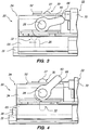
- the plunger 66 when power is provided to the piezo electric unit 62, the plunger 66 is permitted to move inwardly. At that time, if the inner slide IS is moved outwardly relative to the outer slide OS, the latch tab 26 will contact the latch lever 27. Application of sufficient force will cause the latch lever 27 to rotate clockwise, pushing the latch slide 50 to the right and the plunger 66 from its extended position to its retracted position into the piezo electric unit 62. This may be referred to as the "unlocked" position. Upon the latch lever 27 rotating a sufficient degree, the latch tab 26 is permitted to pass there beneath. This allows the inner slide OS to be moved in a first direction to its full extended position relative to the outer slide OS.
- the inner slide OS may be moved back into the outer slide OS. For example, if a drawer attached to the inner slide OS is closed, the drawer, and thus the attached. inner slide OS, is moved inwardly relative to the outer slide OS.
- the latch tab 26 is moved to the right and engages the bottom end 32 of the latch lever 27.
- the latch lever 27 is rotated counterclockwise out of the locked position and into a release position.
- the aperture 56 in the latch slide 50 is sufficiently large to permit this rotation of the latch lever 27. It is noted that this rotation of the latch lever 27 is not inhibited by the piezo electric unit 62, and thus the piezo electric unit 62 need not be powered to permit the inner slide OS to be moved back to the "relatched" position.
- rotation of the latch lever 27 from its locked to its release position is inhibited by the spring 58 which is located between the latching lever 27 and the latch slide 50. This spring 58 is compressed against a stop. Once the latch lever 27 rotates sufficiently, the latch tab 26 is permitted to pass beneath the bottom end 32 thereof. This allows the inner slide OS to be moved in a second directly back to its full retracted position (relative to the outer slide OS).
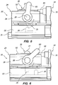
- the manual release lever 60 may be used to manually release the latching mechanism 20.
- the user may pull the manual release lever 60 upwardly (i.e. in the counter-clockwise direction in this figure), thus causing the latching lever 27 to move counter-clockwise, into the position illustrated in Figure 5 .
- the user While the user maintains the latch lever 27 in that position, the user may move the inner slide OS outwardly, as the latch tab 26 is then permitted to pass under the latching lever 27.
- Such a procedure might be necessary if, for example, there were a power failure which prevent activation of the piezo electric unit 62.
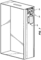
- Figure 7 illustrates the latch mechanism 20 as associated with a drawer D.
- the outer slide OS would be mounted to a support structure, such as the inner wall of a cabinet (not shown).
- the inner slide OS is mounted to an outer side of one of the sides S of the drawer D.
- the drawer D is preferably supported by a corresponding pair of slides at the opposing side thereof.
- the latching mechanism 20 need only be associated with one of the pairs of slides in order to lock or latch the drawer D in the manner detailed above.
- the latch assembly and controller might be mounted to an interior cabinet wall, such as opposite a mounting of the slide assembly, provided that the latch lever can engage the slide assembly from the latch assembly mounting location (such might require providing an access aperture).
- the latching mechanism of the invention has particular utility to use with slides, such as used with drawers.
- the latching mechanism may be used in a variety of other applications.
- the latching mechanism of the invention can be used to control access to a cabinet secured by a door.
- a door is mounted such that a linking member is connected from a point away from the door's axis of rotation to a point on a slide mechanism or assembly.
- Door access can be controlled by applying the latch mechanism, including various features and embodiments described herein, to the slide assembly to control movement thereof.
- the lever arm of the latch mechanism can also be used as a latching feature for a door hasp or to provide control for a latch cam used to capture a door hasp.
- the latch lever of the latching mechanism might be configured to directly interface with a rotating member which is part of, or associated with, such a door hasp (i.e. the "latch tab" may be associated with the door hasp or comprise a portion thereof, and may have a form which varies from that detailed above).
- the latch mechanism may be configured to control movement of the latch lever in the above-described manner, thus controlling movement of the rotating member, such as via a detent feature on that member.
- the various components of the latching mechanism may have a variety of configurations and may be constructed in a variety of manners.
- the various components may be constructed of metal or other materials.
- the components might be constructed by machining, molding or in other manners.
- Various of the components might be combined.
- the piezo electric unit might be provided with integrated mounting feet rather than being mounted with a separate bracket.
- the components of the latching mechanism could be mounted in other fashions than as illustrated.
- the latch assembly and controller might be mounted to a cabinet wall, rather than the outer slide.
- the brackets could be configured differently to permit such attachment, or the components might be mounted so that the latch lever extends through an opening in a cabinet wall and the outer slide mounted thereto, and into the path of the latch tab.
- the plunger of the piezo electric unit is capable of withstanding a very high axial load.
- the components of the latching mechanism are capable of withstanding an opening force of 220 lbs or more without unlatching (i.e. a 220 lb opening force applied to a drawer, pulling the latch tab against the latch lever without permitting the latch tab to pass by the latch lever).
- the plunger of the piezo electric unit is biased outwardly.
- an internal spring may be utilized to bias the plunger outwardly at a force around 5N (.221 lbs).
- Power may selectively be provided to the piezo electric unit (for allowing the latch lever to be moved from its locked to its unlocked position) in various manners.
- a switch button may be provided which selectively allows power to pass from a source to the unit.
- the switch might be key activated to prevent the unit from being powered without authorization.
- the latch mechanism Since the latch mechanism requires very low power to operate, it is possible to operate the mechanism using common batteries, such as one or more AA batteries. Such batteries might be used as a backup power source if the latch mechanism is normally powered via a power bus of a larger assembly with which it is associated.
- the ability to operate the mechanism using such low power requirements is unique to the configuration of the latch mechanism, including the piezo electric controller described herein.
- a DC motor, solenoid or other controllable actuator, device or mechanism (or combination of elements) which is capable of controlling movement of the plunger in the above-described manner, might be utilized.
- a piezo electric controller has a number of particular advantages and benefits.
- the latching mechanism might also have other configurations.
- the latch slide might have other configurations than a plate.
- the latch slide might be eliminated entirely so that the plunger of the piezo electric unit directly engages the latch lever.
- the latch assembly need not include a manual release, or might include more than one such release (such as at both ends of the shaft).
- the latch mechanism might include or be used with one or more sensors.
- the sensors might be associated with the drawer, the slide and/or the latching mechanism to provide feedback to a system controller for monitoring and control of the latching mechanism.
- the condition of the latching mechanism might be controlled and monitored by a control system.
- one or more sensors might be utilized to monitor the position of a drawer. Output of the sensors could be provided to the control system, such as for verifying that the drawer is in its closed position, or for verifying that the latch mechanism is in its locked condition.
- Such sensors might also be used to detect motion of the drawer, such as when the drawer is supposed to be in its locked condition.
- the latching mechanism has numerous advantages. As indicated above, the latching mechanism will withstand high loads without unlatching. The latching mechanism is also secure. Advantageously, the latching mechanism is retained in the locked or latched position when no power is provided to the unit. Thus, in the event of a power failure or the like, the latching mechanism remains locked. In addition, the latching mechanism uses very little power, since power only needs to be provided in order to "unlock" the mechanism.
- latching mechanism can be associated with a slide, rather than just a drawer. This allows the latching mechanism to be located in a more secure and protection position. In addition, this allows the latching mechanism to more effectively prevent movement of the drawer or other object.
Applications Claiming Priority (2)
| Application Number | Priority Date | Filing Date | Title |
|---|---|---|---|
| US11/696,092 US7823993B2 (en) | 2007-04-03 | 2007-04-03 | Piezo actuated slide latching mechanism |
| PCT/US2008/058755 WO2008124349A1 (en) | 2007-04-03 | 2008-03-28 | Peizo actuated slide latching mechanism |
Publications (2)
| Publication Number | Publication Date |
|---|---|
| EP2140086A1 EP2140086A1 (en) | 2010-01-06 |
| EP2140086B1 true EP2140086B1 (en) | 2016-12-14 |
Family
ID=39639305
Family Applications (1)
| Application Number | Title | Priority Date | Filing Date |
|---|---|---|---|
| EP08732994.2A Active EP2140086B1 (en) | 2007-04-03 | 2008-03-28 | Piezo actuated slide latching mechanism |
Country Status (12)
| Country | Link |
|---|---|
| US (2) | US7823993B2 (ru) |
| EP (1) | EP2140086B1 (ru) |
| JP (1) | JP2010523852A (ru) |
| CN (1) | CN101680247B (ru) |
| AU (1) | AU2008237446B2 (ru) |
| BR (1) | BRPI0809854B1 (ru) |
| CA (1) | CA2679731C (ru) |
| ES (1) | ES2618577T3 (ru) |
| NZ (1) | NZ580181A (ru) |
| RU (1) | RU2463423C2 (ru) |
| WO (1) | WO2008124349A1 (ru) |
| ZA (1) | ZA200907260B (ru) |
Families Citing this family (33)
| Publication number | Priority date | Publication date | Assignee | Title |
|---|---|---|---|---|
| KR100700776B1 (ko) * | 2005-03-02 | 2007-03-27 | 엘지전자 주식회사 | 냉장고, 냉장고의 도어제어장치 및 도어제어방법 |
| CN101330850B (zh) * | 2005-12-15 | 2012-05-23 | 尤利乌斯·布卢姆有限公司 | 带有至少一个第一家具部件和一个第二家具部件的家具 |
| KR200456982Y1 (ko) * | 2007-03-30 | 2011-11-30 | 주식회사 아이레보 | 일체형 구동부 데드 볼트를 구비한 튜블러형 디지털 도어록 |
| DE102007057410B3 (de) * | 2007-11-27 | 2009-07-30 | Uhde Gmbh | Mechanismus und Verfahren zur automatisierbaren Verriegelung von Türen, Türkörpern oder Türrahmen horizontaler Koksofenkammern |
| US8393653B2 (en) * | 2008-08-11 | 2013-03-12 | D & D Group Pty Ltd. | Magnetic safety latch |
| US8067915B2 (en) * | 2008-12-31 | 2011-11-29 | General Electric Company | Electronic control circuit for a powered appliance drawer |
| US9121197B2 (en) | 2009-01-09 | 2015-09-01 | Automed Technologies, Inc. | Cabinet system with improved drawer security |
| US8103379B2 (en) | 2009-01-09 | 2012-01-24 | Automed Technologies, Inc. | Medication cabinetry |
| US8588966B2 (en) | 2009-01-09 | 2013-11-19 | Automed Technologies, Inc. | Cabinet system |
| US8744621B2 (en) | 2009-01-09 | 2014-06-03 | Automed Technologies, Inc. | Medical cabinet access belt optimization system |
| WO2010129303A2 (en) | 2009-04-27 | 2010-11-11 | Accuride International Inc. | Drawer slide and locking mechanism |
| US8970344B2 (en) * | 2009-07-14 | 2015-03-03 | Compx International Inc. | Method and system for data control in electronic locks |
| US8516864B2 (en) | 2009-09-10 | 2013-08-27 | Compx International Inc. | Electronic latch mechanism |
| US8742889B2 (en) * | 2009-09-29 | 2014-06-03 | Compx International Inc. | Apparatus and method for electronic access control |
| KR101580447B1 (ko) * | 2009-10-26 | 2015-12-29 | 삼성전자주식회사 | 냉장고의 자동 도어 닫힘 장치 및 이를 포함하는 냉장고 |
| US8746908B2 (en) | 2010-01-27 | 2014-06-10 | Automed Technologies, Inc. | Medical supply cabinet with lighting features |
| US20120023675A1 (en) * | 2010-07-30 | 2012-02-02 | Hutchison Stephen E | Tool-removable slide-off footboard |
| GB2518789B (en) | 2012-07-18 | 2020-05-13 | Accuride Int Inc | Drawer slide and electronically actuated locking mechanism |
| US10591201B2 (en) | 2013-01-18 | 2020-03-17 | Triteq Lock And Security, Llc | Cooler lock |
| ES2486092B1 (es) * | 2013-02-13 | 2015-12-22 | Ojmar, S.A. | Sistema de cierre antivuelco para cajones de muebles, con módulo de bloqueo electrónico |
| CA2922400C (en) | 2013-05-15 | 2019-11-05 | William Denison | Lock |
| EP3027829B1 (en) * | 2013-08-02 | 2019-12-18 | Accuride International Inc. | Cabinet gang lock system for electrically lockable slides |
| DE102013013694B3 (de) * | 2013-08-16 | 2014-12-11 | Audi Ag | Anzeigeeinrichtung für ein Kraftfahrzeug |
| US9926955B1 (en) * | 2014-08-08 | 2018-03-27 | Taylor & Lego Holdings, LLC | Latch |
| US20160138301A1 (en) * | 2014-11-14 | 2016-05-19 | The Boeing Company | Self-contained electronic stowage bin system |
| US10662686B2 (en) | 2016-09-30 | 2020-05-26 | Barrette Outdoor Living, Inc. | Magnetic safety gate latch |
| WO2018125922A1 (en) | 2016-12-30 | 2018-07-05 | Baxter International Inc. | Infusion pump door seal for vertical intravenous tubes |
| AU2017388223B2 (en) | 2016-12-30 | 2023-08-31 | Baxter Healthcare Sa | Anti-occlusion intravenous tube port |
| US11176765B2 (en) | 2017-08-21 | 2021-11-16 | Compx International Inc. | System and method for combined electronic inventory data and access control |
| CN108784036A (zh) * | 2018-06-27 | 2018-11-13 | 深圳市联新移动医疗科技有限公司 | 带锁止结构的滑轨装置及其抽屉 |
| DE202018105346U1 (de) * | 2018-09-18 | 2019-12-19 | Vogelsang Gmbh & Co. Kg | Absaugvorrichtung zum Abführen eines Mischfluids, insbesondere Fäkalien enthaltend,aus einem Sammelbehälter |
| US11157789B2 (en) | 2019-02-18 | 2021-10-26 | Compx International Inc. | Medicinal dosage storage and method for combined electronic inventory data and access control |
| EP4290035A3 (en) | 2019-08-22 | 2024-04-03 | Carrier Corporation | Latch assembly for vertical door |
Family Cites Families (24)
| Publication number | Priority date | Publication date | Assignee | Title |
|---|---|---|---|---|
| DE3149972C2 (de) * | 1981-12-17 | 1983-11-03 | ADS-Anker GmbH, 4800 Bielefeld | Schubladenführung für Registrierkassen oder Kassentische |
| US4424426A (en) * | 1982-06-24 | 1984-01-03 | M-S Corporation | Battery powered drawer opening device |
| SU1222805A1 (ru) * | 1984-10-03 | 1986-04-07 | Предприятие П/Я А-2001 | Устройство запирани много щичного шкафа |
| CA1303867C (en) | 1986-01-23 | 1992-06-23 | David Charles Blake | Security system |
| ES2066885T3 (es) | 1989-01-19 | 1995-03-16 | Mib Elettronica | Dispositivo para proteger y manipular billetes bancarios y valores. |
| US5014875A (en) | 1989-03-01 | 1991-05-14 | Pyxis Corporation | Medication dispenser station |
| AT401334B (de) | 1990-07-31 | 1996-08-26 | Blum Gmbh Julius | Schliessvorrichtung für schubladen |
| US5379184A (en) * | 1991-08-30 | 1995-01-03 | Unisys Corporation | Pry-in/pry-out disk drive receptacle |
| NZ248716A (en) | 1993-09-21 | 1996-10-28 | Smart Systems Ltd | Drawer opening prevented by ratchet which is overridden by activation of electomagnet |
| FI105907B (fi) | 1996-04-30 | 2000-10-31 | Aarre Toivo Juhani Salomaa | Hyllyrakenne |
| US6682156B2 (en) * | 1998-07-16 | 2004-01-27 | Supply Point Systems Ltd. | Apparatus for controlling access to a plurality of drawers |
| AT413631B (de) * | 2001-12-27 | 2006-04-15 | Blum Gmbh Julius | Anordnung mit einem bewegbaren möbelteil, mit einer antriebseinheit und mit einer regeleinrichtung |
| JP4098541B2 (ja) * | 2002-03-20 | 2008-06-11 | 株式会社岡村製作所 | 引出し式キャビネット |
| GB0208508D0 (en) | 2002-04-12 | 2002-05-22 | Pbt Ip Ltd | Electrically controlled door lock |
| AU2003297585A1 (en) | 2002-11-27 | 2004-06-23 | Knape And Vogt Manufacturing Co. | Interlock mechanism for lateral file cabinets |
| GB2398826B (en) * | 2003-02-28 | 2006-02-01 | Pbt | Electrically controllable latch mechanism |
| GB0321439D0 (en) | 2003-09-12 | 2003-10-15 | Pbt Ip Ltd | Locking mechanism |
| ITMC20030144A1 (it) * | 2003-12-05 | 2005-06-06 | Compagnucci Spa Ora Compagnucci Ho Lding Spa | Dispositivo per la chiusura automatica ed ammortizzata dei cassetti e delle strutture estraibili per mobili. |
| JP4446825B2 (ja) * | 2004-07-21 | 2010-04-07 | 株式会社ニフコ | スライド補助装置 |
| JP2006183359A (ja) * | 2004-12-28 | 2006-07-13 | Kokuyo Co Ltd | 什器 |
| DE102005014343C5 (de) | 2005-03-24 | 2012-11-08 | ASTRA Gesellschaft für Asset Management mbH & Co. KG | Aufbewahrungseinrichtung |
| CN2815111Y (zh) * | 2005-05-09 | 2006-09-13 | 翁国展 | 可组合联动锁固装置 |
| US20070046159A1 (en) * | 2005-08-25 | 2007-03-01 | Knape & Vogt Manufacturing Co. | Motion control bracket with integrated motion control device |
| EP1785063B1 (de) * | 2005-11-10 | 2012-03-14 | Grass GmbH | Vorrichtung zum Öffnen und Schliessen eines bewegbaren Möbelteils und Möbelteil |
-
2007
- 2007-04-03 US US11/696,092 patent/US7823993B2/en active Active
-
2008
- 2008-03-28 JP JP2010502222A patent/JP2010523852A/ja active Pending
- 2008-03-28 EP EP08732994.2A patent/EP2140086B1/en active Active
- 2008-03-28 WO PCT/US2008/058755 patent/WO2008124349A1/en active Application Filing
- 2008-03-28 AU AU2008237446A patent/AU2008237446B2/en active Active
- 2008-03-28 ES ES08732994.2T patent/ES2618577T3/es active Active
- 2008-03-28 NZ NZ580181A patent/NZ580181A/en not_active IP Right Cessation
- 2008-03-28 RU RU2009140405/12A patent/RU2463423C2/ru active
- 2008-03-28 CA CA2679731A patent/CA2679731C/en active Active
- 2008-03-28 CN CN2008800112546A patent/CN101680247B/zh active Active
- 2008-03-28 BR BRPI0809854-9A patent/BRPI0809854B1/pt active IP Right Grant
-
2009
- 2009-10-16 ZA ZA200907260A patent/ZA200907260B/xx unknown
-
2010
- 2010-09-29 US US12/893,984 patent/US8096628B2/en active Active
Also Published As
| Publication number | Publication date |
|---|---|
| BRPI0809854B1 (pt) | 2018-11-13 |
| CN101680247B (zh) | 2013-07-03 |
| EP2140086A1 (en) | 2010-01-06 |
| JP2010523852A (ja) | 2010-07-15 |
| RU2463423C2 (ru) | 2012-10-10 |
| US20080246286A1 (en) | 2008-10-09 |
| AU2008237446A1 (en) | 2008-10-16 |
| ZA200907260B (en) | 2010-07-28 |
| US7823993B2 (en) | 2010-11-02 |
| AU2008237446B2 (en) | 2013-05-23 |
| CA2679731C (en) | 2013-02-12 |
| US20110012374A1 (en) | 2011-01-20 |
| BRPI0809854A8 (pt) | 2016-01-26 |
| CN101680247A (zh) | 2010-03-24 |
| WO2008124349A1 (en) | 2008-10-16 |
| US8096628B2 (en) | 2012-01-17 |
| RU2009140405A (ru) | 2011-05-10 |
| NZ580181A (en) | 2011-10-28 |
| BRPI0809854A2 (pt) | 2014-09-30 |
| CA2679731A1 (en) | 2008-10-16 |
| ES2618577T3 (es) | 2017-06-21 |
Similar Documents
| Publication | Publication Date | Title |
|---|---|---|
| EP2140086B1 (en) | Piezo actuated slide latching mechanism | |
| US9797165B2 (en) | Electric latch retraction bar | |
| US10544609B2 (en) | Cam-operated latch assembly | |
| US8851532B2 (en) | Electric strike | |
| US20180177294A1 (en) | Drawer slide and locking mechanism | |
| JP2017534010A (ja) | カムラッチ | |
| US10107015B2 (en) | Electric latch retraction push-bar device | |
| JP5385294B2 (ja) | ラッチアクチュエータ及びそれを用いるラッチ | |
| US10017964B2 (en) | Latch mechanism for an exit device | |
| US8299377B2 (en) | Interlocks for withdrawable breakers | |
| US20240008202A1 (en) | Automatic unlocking system for it cabinet | |
| EP4206427A1 (en) | A latch assembly for use in a lock mechanism | |
| CN117306963A (zh) | 用于it机柜的自动解锁系统 | |
| EP2390441A1 (en) | Lock system | |
| NZ701861B (en) | Lock assembly with electrically controlled lock mechanism |
Legal Events
| Date | Code | Title | Description |
|---|---|---|---|
| PUAI | Public reference made under article 153(3) epc to a published international application that has entered the european phase |
Free format text: ORIGINAL CODE: 0009012 |
|
| 17P | Request for examination filed |
Effective date: 20091009 |
|
| AK | Designated contracting states |
Kind code of ref document: A1 Designated state(s): AT BE BG CH CY CZ DE DK EE ES FI FR GB GR HR HU IE IS IT LI LT LU LV MC MT NL NO PL PT RO SE SI SK TR |
|
| 17Q | First examination report despatched |
Effective date: 20100222 |
|
| DAX | Request for extension of the european patent (deleted) | ||
| REG | Reference to a national code |
Ref country code: HK Ref legal event code: DE Ref document number: 1139720 Country of ref document: HK |
|
| RAP1 | Party data changed (applicant data changed or rights of an application transferred) |
Owner name: CAREFUSION 303, INC. |
|
| GRAP | Despatch of communication of intention to grant a patent |
Free format text: ORIGINAL CODE: EPIDOSNIGR1 |
|
| INTG | Intention to grant announced |
Effective date: 20160715 |
|
| REG | Reference to a national code |
Ref country code: HK Ref legal event code: WD Ref document number: 1139720 Country of ref document: HK |
|
| GRAS | Grant fee paid |
Free format text: ORIGINAL CODE: EPIDOSNIGR3 |
|
| GRAA | (expected) grant |
Free format text: ORIGINAL CODE: 0009210 |
|
| AK | Designated contracting states |
Kind code of ref document: B1 Designated state(s): AT BE BG CH CY CZ DE DK EE ES FI FR GB GR HR HU IE IS IT LI LT LU LV MC MT NL NO PL PT RO SE SI SK TR |
|
| REG | Reference to a national code |
Ref country code: GB Ref legal event code: FG4D |
|
| REG | Reference to a national code |
Ref country code: CH Ref legal event code: EP |
|
| REG | Reference to a national code |
Ref country code: IE Ref legal event code: FG4D |
|
| REG | Reference to a national code |
Ref country code: AT Ref legal event code: REF Ref document number: 853748 Country of ref document: AT Kind code of ref document: T Effective date: 20170115 |
|
| REG | Reference to a national code |
Ref country code: DE Ref legal event code: R096 Ref document number: 602008047860 Country of ref document: DE |
|
| REG | Reference to a national code |
Ref country code: FR Ref legal event code: PLFP Year of fee payment: 10 |
|
| PG25 | Lapsed in a contracting state [announced via postgrant information from national office to epo] |
Ref country code: LV Free format text: LAPSE BECAUSE OF FAILURE TO SUBMIT A TRANSLATION OF THE DESCRIPTION OR TO PAY THE FEE WITHIN THE PRESCRIBED TIME-LIMIT Effective date: 20161214 |
|
| REG | Reference to a national code |
Ref country code: NL Ref legal event code: FP |
|
| REG | Reference to a national code |
Ref country code: LT Ref legal event code: MG4D |
|
| PG25 | Lapsed in a contracting state [announced via postgrant information from national office to epo] |
Ref country code: NO Free format text: LAPSE BECAUSE OF FAILURE TO SUBMIT A TRANSLATION OF THE DESCRIPTION OR TO PAY THE FEE WITHIN THE PRESCRIBED TIME-LIMIT Effective date: 20170314 Ref country code: LT Free format text: LAPSE BECAUSE OF FAILURE TO SUBMIT A TRANSLATION OF THE DESCRIPTION OR TO PAY THE FEE WITHIN THE PRESCRIBED TIME-LIMIT Effective date: 20161214 Ref country code: GR Free format text: LAPSE BECAUSE OF FAILURE TO SUBMIT A TRANSLATION OF THE DESCRIPTION OR TO PAY THE FEE WITHIN THE PRESCRIBED TIME-LIMIT Effective date: 20170315 Ref country code: SE Free format text: LAPSE BECAUSE OF FAILURE TO SUBMIT A TRANSLATION OF THE DESCRIPTION OR TO PAY THE FEE WITHIN THE PRESCRIBED TIME-LIMIT Effective date: 20161214 |
|
| REG | Reference to a national code |
Ref country code: AT Ref legal event code: MK05 Ref document number: 853748 Country of ref document: AT Kind code of ref document: T Effective date: 20161214 |
|
| PG25 | Lapsed in a contracting state [announced via postgrant information from national office to epo] |
Ref country code: FI Free format text: LAPSE BECAUSE OF FAILURE TO SUBMIT A TRANSLATION OF THE DESCRIPTION OR TO PAY THE FEE WITHIN THE PRESCRIBED TIME-LIMIT Effective date: 20161214 Ref country code: HR Free format text: LAPSE BECAUSE OF FAILURE TO SUBMIT A TRANSLATION OF THE DESCRIPTION OR TO PAY THE FEE WITHIN THE PRESCRIBED TIME-LIMIT Effective date: 20161214 |
|
| REG | Reference to a national code |
Ref country code: ES Ref legal event code: FG2A Ref document number: 2618577 Country of ref document: ES Kind code of ref document: T3 Effective date: 20170621 |
|
| PG25 | Lapsed in a contracting state [announced via postgrant information from national office to epo] |
Ref country code: EE Free format text: LAPSE BECAUSE OF FAILURE TO SUBMIT A TRANSLATION OF THE DESCRIPTION OR TO PAY THE FEE WITHIN THE PRESCRIBED TIME-LIMIT Effective date: 20161214 Ref country code: CZ Free format text: LAPSE BECAUSE OF FAILURE TO SUBMIT A TRANSLATION OF THE DESCRIPTION OR TO PAY THE FEE WITHIN THE PRESCRIBED TIME-LIMIT Effective date: 20161214 Ref country code: RO Free format text: LAPSE BECAUSE OF FAILURE TO SUBMIT A TRANSLATION OF THE DESCRIPTION OR TO PAY THE FEE WITHIN THE PRESCRIBED TIME-LIMIT Effective date: 20161214 Ref country code: SK Free format text: LAPSE BECAUSE OF FAILURE TO SUBMIT A TRANSLATION OF THE DESCRIPTION OR TO PAY THE FEE WITHIN THE PRESCRIBED TIME-LIMIT Effective date: 20161214 Ref country code: IS Free format text: LAPSE BECAUSE OF FAILURE TO SUBMIT A TRANSLATION OF THE DESCRIPTION OR TO PAY THE FEE WITHIN THE PRESCRIBED TIME-LIMIT Effective date: 20170414 |
|
| PG25 | Lapsed in a contracting state [announced via postgrant information from national office to epo] |
Ref country code: PT Free format text: LAPSE BECAUSE OF FAILURE TO SUBMIT A TRANSLATION OF THE DESCRIPTION OR TO PAY THE FEE WITHIN THE PRESCRIBED TIME-LIMIT Effective date: 20170414 Ref country code: AT Free format text: LAPSE BECAUSE OF FAILURE TO SUBMIT A TRANSLATION OF THE DESCRIPTION OR TO PAY THE FEE WITHIN THE PRESCRIBED TIME-LIMIT Effective date: 20161214 Ref country code: PL Free format text: LAPSE BECAUSE OF FAILURE TO SUBMIT A TRANSLATION OF THE DESCRIPTION OR TO PAY THE FEE WITHIN THE PRESCRIBED TIME-LIMIT Effective date: 20161214 Ref country code: BG Free format text: LAPSE BECAUSE OF FAILURE TO SUBMIT A TRANSLATION OF THE DESCRIPTION OR TO PAY THE FEE WITHIN THE PRESCRIBED TIME-LIMIT Effective date: 20170314 Ref country code: BE Free format text: LAPSE BECAUSE OF FAILURE TO SUBMIT A TRANSLATION OF THE DESCRIPTION OR TO PAY THE FEE WITHIN THE PRESCRIBED TIME-LIMIT Effective date: 20161214 |
|
| REG | Reference to a national code |
Ref country code: DE Ref legal event code: R097 Ref document number: 602008047860 Country of ref document: DE |
|
| PLBE | No opposition filed within time limit |
Free format text: ORIGINAL CODE: 0009261 |
|
| STAA | Information on the status of an ep patent application or granted ep patent |
Free format text: STATUS: NO OPPOSITION FILED WITHIN TIME LIMIT |
|
| REG | Reference to a national code |
Ref country code: CH Ref legal event code: PL |
|
| 26N | No opposition filed |
Effective date: 20170915 |
|
| PG25 | Lapsed in a contracting state [announced via postgrant information from national office to epo] |
Ref country code: MC Free format text: LAPSE BECAUSE OF FAILURE TO SUBMIT A TRANSLATION OF THE DESCRIPTION OR TO PAY THE FEE WITHIN THE PRESCRIBED TIME-LIMIT Effective date: 20161214 Ref country code: DK Free format text: LAPSE BECAUSE OF FAILURE TO SUBMIT A TRANSLATION OF THE DESCRIPTION OR TO PAY THE FEE WITHIN THE PRESCRIBED TIME-LIMIT Effective date: 20161214 |
|
| REG | Reference to a national code |
Ref country code: IE Ref legal event code: MM4A |
|
| PG25 | Lapsed in a contracting state [announced via postgrant information from national office to epo] |
Ref country code: LU Free format text: LAPSE BECAUSE OF NON-PAYMENT OF DUE FEES Effective date: 20170328 |
|
| REG | Reference to a national code |
Ref country code: FR Ref legal event code: PLFP Year of fee payment: 11 |
|
| PG25 | Lapsed in a contracting state [announced via postgrant information from national office to epo] |
Ref country code: CH Free format text: LAPSE BECAUSE OF NON-PAYMENT OF DUE FEES Effective date: 20170331 Ref country code: SI Free format text: LAPSE BECAUSE OF FAILURE TO SUBMIT A TRANSLATION OF THE DESCRIPTION OR TO PAY THE FEE WITHIN THE PRESCRIBED TIME-LIMIT Effective date: 20161214 Ref country code: LI Free format text: LAPSE BECAUSE OF NON-PAYMENT OF DUE FEES Effective date: 20170331 Ref country code: IE Free format text: LAPSE BECAUSE OF NON-PAYMENT OF DUE FEES Effective date: 20170328 |
|
| PG25 | Lapsed in a contracting state [announced via postgrant information from national office to epo] |
Ref country code: MT Free format text: LAPSE BECAUSE OF NON-PAYMENT OF DUE FEES Effective date: 20170328 |
|
| PG25 | Lapsed in a contracting state [announced via postgrant information from national office to epo] |
Ref country code: HU Free format text: LAPSE BECAUSE OF FAILURE TO SUBMIT A TRANSLATION OF THE DESCRIPTION OR TO PAY THE FEE WITHIN THE PRESCRIBED TIME-LIMIT; INVALID AB INITIO Effective date: 20080328 |
|
| PG25 | Lapsed in a contracting state [announced via postgrant information from national office to epo] |
Ref country code: CY Free format text: LAPSE BECAUSE OF NON-PAYMENT OF DUE FEES Effective date: 20161214 |
|
| PG25 | Lapsed in a contracting state [announced via postgrant information from national office to epo] |
Ref country code: TR Free format text: LAPSE BECAUSE OF FAILURE TO SUBMIT A TRANSLATION OF THE DESCRIPTION OR TO PAY THE FEE WITHIN THE PRESCRIBED TIME-LIMIT Effective date: 20161214 |
|
| PGFP | Annual fee paid to national office [announced via postgrant information from national office to epo] |
Ref country code: FR Payment date: 20230222 Year of fee payment: 16 |
|
| PGFP | Annual fee paid to national office [announced via postgrant information from national office to epo] |
Ref country code: IT Payment date: 20230221 Year of fee payment: 16 |
|
| PGFP | Annual fee paid to national office [announced via postgrant information from national office to epo] |
Ref country code: ES Payment date: 20230403 Year of fee payment: 16 |
|
| PGFP | Annual fee paid to national office [announced via postgrant information from national office to epo] |
Ref country code: NL Payment date: 20240220 Year of fee payment: 17 |
|
| PGFP | Annual fee paid to national office [announced via postgrant information from national office to epo] |
Ref country code: DE Payment date: 20240220 Year of fee payment: 17 Ref country code: GB Payment date: 20240220 Year of fee payment: 17 |