EP2139752B1 - Transmission par lien souple reniforme - Google Patents
Transmission par lien souple reniformeInfo
- Publication number
- EP2139752B1 EP2139752B1 EP08715561A EP08715561A EP2139752B1 EP 2139752 B1 EP2139752 B1 EP 2139752B1 EP 08715561 A EP08715561 A EP 08715561A EP 08715561 A EP08715561 A EP 08715561A EP 2139752 B1 EP2139752 B1 EP 2139752B1
- Authority
- EP
- European Patent Office
- Prior art keywords
- mechanism according
- output shaft
- toothed
- component
- input shaft
- Prior art date
- Legal status (The legal status is an assumption and is not a legal conclusion. Google has not performed a legal analysis and makes no representation as to the accuracy of the status listed.)
- Active
Links
- 230000007246 mechanism Effects 0.000 claims description 78
- 230000005540 biological transmission Effects 0.000 claims description 43
- 230000008878 coupling Effects 0.000 claims description 41
- 238000010168 coupling process Methods 0.000 claims description 41
- 238000005859 coupling reaction Methods 0.000 claims description 41
- 230000008859 change Effects 0.000 claims description 16
- 229910000831 Steel Inorganic materials 0.000 claims description 12
- 239000010959 steel Substances 0.000 claims description 12
- 238000006073 displacement reaction Methods 0.000 claims description 8
- 238000000034 method Methods 0.000 claims description 8
- 230000008569 process Effects 0.000 claims description 8
- 229920000271 Kevlar® Polymers 0.000 claims description 4
- 229920003235 aromatic polyamide Polymers 0.000 claims description 4
- 238000005516 engineering process Methods 0.000 claims description 4
- 239000002657 fibrous material Substances 0.000 claims description 4
- 239000004761 kevlar Substances 0.000 claims description 4
- 229920002635 polyurethane Polymers 0.000 claims description 2
- 239000004814 polyurethane Substances 0.000 claims description 2
- 241000531908 Aramides Species 0.000 claims 1
- OKTJSMMVPCPJKN-UHFFFAOYSA-N Carbon Chemical compound [C] OKTJSMMVPCPJKN-UHFFFAOYSA-N 0.000 claims 1
- 229910052799 carbon Inorganic materials 0.000 claims 1
- 230000000694 effects Effects 0.000 claims 1
- 239000000835 fiber Substances 0.000 claims 1
- 238000013461 design Methods 0.000 description 7
- 238000010276 construction Methods 0.000 description 6
- 238000004519 manufacturing process Methods 0.000 description 6
- 230000006378 damage Effects 0.000 description 5
- 238000013519 translation Methods 0.000 description 5
- 230000014616 translation Effects 0.000 description 5
- 239000004760 aramid Substances 0.000 description 3
- 230000008901 benefit Effects 0.000 description 3
- 238000002485 combustion reaction Methods 0.000 description 3
- 230000007613 environmental effect Effects 0.000 description 3
- 210000002414 leg Anatomy 0.000 description 3
- 238000003825 pressing Methods 0.000 description 3
- 239000000725 suspension Substances 0.000 description 3
- 229920000049 Carbon (fiber) Polymers 0.000 description 2
- 208000027418 Wounds and injury Diseases 0.000 description 2
- 239000004917 carbon fiber Substances 0.000 description 2
- 239000007822 coupling agent Substances 0.000 description 2
- 230000007423 decrease Effects 0.000 description 2
- 208000014674 injury Diseases 0.000 description 2
- 239000000463 material Substances 0.000 description 2
- VNWKTOKETHGBQD-UHFFFAOYSA-N methane Chemical compound C VNWKTOKETHGBQD-UHFFFAOYSA-N 0.000 description 2
- 238000007789 sealing Methods 0.000 description 2
- 125000006850 spacer group Chemical group 0.000 description 2
- XLYOFNOQVPJJNP-UHFFFAOYSA-N water Substances O XLYOFNOQVPJJNP-UHFFFAOYSA-N 0.000 description 2
- 241001136792 Alle Species 0.000 description 1
- 229920002430 Fibre-reinforced plastic Polymers 0.000 description 1
- 230000000712 assembly Effects 0.000 description 1
- 238000000429 assembly Methods 0.000 description 1
- 238000004140 cleaning Methods 0.000 description 1
- 238000004891 communication Methods 0.000 description 1
- 238000011109 contamination Methods 0.000 description 1
- 238000001816 cooling Methods 0.000 description 1
- 238000005265 energy consumption Methods 0.000 description 1
- 239000011151 fibre-reinforced plastic Substances 0.000 description 1
- 230000005484 gravity Effects 0.000 description 1
- 238000010348 incorporation Methods 0.000 description 1
- 238000003780 insertion Methods 0.000 description 1
- 230000037431 insertion Effects 0.000 description 1
- 210000003127 knee Anatomy 0.000 description 1
- 230000007774 longterm Effects 0.000 description 1
- 239000000696 magnetic material Substances 0.000 description 1
- 238000012423 maintenance Methods 0.000 description 1
- 210000003205 muscle Anatomy 0.000 description 1
- 230000007935 neutral effect Effects 0.000 description 1
- 239000002245 particle Substances 0.000 description 1
- 230000002093 peripheral effect Effects 0.000 description 1
- 230000000284 resting effect Effects 0.000 description 1
- 238000003860 storage Methods 0.000 description 1
- 239000011800 void material Substances 0.000 description 1
Images


Classifications
-
- B—PERFORMING OPERATIONS; TRANSPORTING
- B62—LAND VEHICLES FOR TRAVELLING OTHERWISE THAN ON RAILS
- B62M—RIDER PROPULSION OF WHEELED VEHICLES OR SLEDGES; POWERED PROPULSION OF SLEDGES OR SINGLE-TRACK CYCLES; TRANSMISSIONS SPECIALLY ADAPTED FOR SUCH VEHICLES
- B62M9/00—Transmissions characterised by use of an endless chain, belt, or the like
- B62M9/04—Transmissions characterised by use of an endless chain, belt, or the like of changeable ratio
-
- B—PERFORMING OPERATIONS; TRANSPORTING
- B62—LAND VEHICLES FOR TRAVELLING OTHERWISE THAN ON RAILS
- B62M—RIDER PROPULSION OF WHEELED VEHICLES OR SLEDGES; POWERED PROPULSION OF SLEDGES OR SINGLE-TRACK CYCLES; TRANSMISSIONS SPECIALLY ADAPTED FOR SUCH VEHICLES
- B62M11/00—Transmissions characterised by the use of interengaging toothed wheels or frictionally-engaging wheels
- B62M11/04—Transmissions characterised by the use of interengaging toothed wheels or frictionally-engaging wheels of changeable ratio
- B62M11/06—Transmissions characterised by the use of interengaging toothed wheels or frictionally-engaging wheels of changeable ratio with spur gear wheels
Definitions
- Switchable transmissions have become indispensable in the field of motorized vehicles for the past 100 years. They are also used in drive technology on numerous machines. Very often, these are gearbox designs that work with the help of gears as a spur gear or epicyclic gear (planetary gear). However, the production technology of this transmission is usually very complicated and expensive. Since these power-transmitting transmission components are usually made of steel, the weight is currently always in the focus of criticism and is to be regarded as a disadvantage. For example, lighter transmissions would Lower energy consumption.
- the novelty to be described below can be used in all imaginable product branches and, especially with regard to the low weight, is excellently suitable for use in vehicles, since fiber-reinforced plastics are used as force-transmitting components.
- land vehicles, aircraft and watercraft can be seen, which can be equipped with internal combustion engines, electric motors or other units.
- a use in vehicles is conceivable, which are powered by muscle power.
- the vehicles must be exceptionally light. The functional description of the transmission should be made for this reason, for example, on a bicycle.
- a rotatable bottom bracket with one or more chainrings is mounted on the frame, which forms the main component of the bicycle with all its mounting points for the front fork, the seat post and the rear wheel.
- a cassette consisting of up to ten different sized pinions.
- a derailleur is mounted, whose task is to guide the chain on the pinions of the cassette and to enable switching operations.
- Bicycles with a shifting system as described above are generally referred to as derailleur bicycles.
- the planetary gear is brought by the primary drive to a higher speed to withstand the forces acting.
- this design decreases the efficiency of the drive. This is to be seen as a disadvantage compared to the invention.
- similar transmissions are for example US 5,553,510 . US 4,955,247 . US 5,924,950 . DE 20 201 787 U1 . WO 2006/039880 A1 . US 2004/0067804 A1 and US 2004/0066017 A1 known. Their structure is usually very difficult and complex.
- the invention provides a lightweight and simply built solution for the cited type of transmission. All of these transmissions produce different ratios between two parallel shafts. In this case, one of the shafts is usually the drive shaft and another shaft is the output shaft.
- the drive shaft is also referred to below as the input shaft.
- the output shaft is also referred to below as the output shaft. If in the following only the term wave is used, then the input or the output wave is meant.
- the invention thus improves multiple transmission with input shaft and output shaft, wherein the input shaft is configured to receive the input torque and the output shaft is usually led out of the transmission housing and is configured at this end for forwarding the torque to the wheels of the vehicle.
- the housing for example, Zaffenson are mounted in parallel on the input shaft and the output shaft and connected in pairs with traction means. With the help of a shift control the Glasstofftex can be coupled to the output shaft.
- the vehicle may be, for example, a bicycle, where the input shaft for receiving cranks is designed there and guided out with its two ends from the transmission housing.
- the output shaft has at its end a pinion for transmitting torque to the rear wheel.
- the vehicle may be a motorcycle in which the transmission is advantageously located behind the crankcase.
- the input shaft is suitably connected to the crankshaft.
- the output shaft transmits the torque through another machine element (eg chain, timing belt, cardan) to the rear wheel.
- Another machine element eg chain, timing belt, cardan
- Such a traction mechanism is for example from the US 4,158,316 known.
- This gear several sprockets with different diameters are rotatably mounted on the axle. Through a coupling, the sprockets can be rotatably connected to the shaft and thus transmit a torque.
- the disadvantage of this invention is on the one hand in the high weight, in particular by the use of a steel chain, on the other hand in the large space requirement, the complexity of the couplings and the clutch control.
- a similar traction mechanism is for example from the US 2004/0067804 A1 and US 2004/0066017 A1 known.
- different Buchstoffgebauer are mounted on the drive and output shaft, which are connected in pairs with traction means.
- Different transmission ratios are achieved in that a switching element is axially displaced within the output shaft by means of a cable.
- a connecting element on the switching element engages in the desired Werstoffrad and generates a rotationally fixed connection between the output shaft and Gebrad.
- the structure described has disadvantages, which are explained in more detail below.
- Traction drives generally have a discrete center distance, which depends solely on the pitch and the length of the traction device, and the diameter or the number of teeth of the Switzerlandstoffmannmann used.
- At least one component within the coupling means has the properties of a permanent magnet with a magnetic north and south pole and the state of the coupling means by changing an additional magnetic field within or in the immediate vicinity of the coupling means changes and that during at least one switching operation of the Condition of at least two coupling means changes simultaneously and that at least one coupling means can only transmit torques in one direction of rotation, it is impossible that accidentally by a switching error in a Neutral position of the transmission is switched, which may cause damage to the transmission and possibly injury in a cyclist. Since only magnetic fields are changed for a gear change, switching changes under load and in the state are possible.
- At least one component assumes a position at a distance relative to a toothing of a coupling means, after two identically poled magnetic fields have moved toward one another, it is possible to ensure that the switching forces are reduced in comparison to the prior art.
- the positive coupling means is formed by freewheel teeth, which can engage in a toothing, the overall structure can be kept very simple.
- the freewheel teeth are arranged symmetrically to the toothing within the coupling means in order to transmit the forces uniformly.
- An advantageous control of the transmission is implemented when the change of the magnetic field is achieved by axial displacement of permanent magnets along the axis of rotation of the shaft on which the coupling means is located.
- gearbox without space-related access to the interior of the waves can be constructed according to the novelty, when the axial displacement of the permanent magnet outside the input shaft is completed.
- the permanent magnets are inserted in different polarity in the spool component, so that the production costs can be kept low by the use of many equal parts.
- a very inexpensive solution for the axial movement of the spool component is achieved when the spool component is in communication with a traction means.
- the spool component assumes detent points within its axial movement relative to the shaft to reproducibly alter the magnetic field within or in the immediate vicinity of the coupling means.
- the switching precision is improved.
- the necessary switching forces are kept low if the positive non-rotatable connection between the shaft and the gear can be canceled with the help of the energy that was stored in the magnetic field prior to decoupling.
- a fully electronic control of the state of the coupling means can be achieved when the change of an additional magnetic field within or in the immediate vicinity of the coupling means is accomplished by electromagnets. This may be advantageous in some applications of the transmission.
- the gearbox is protected against external contamination if the frame of the gearbox is designed as a closed housing.
- the dead weight is greatly reduced when the gear ratios located between the input shaft and the output shaft are designed as traction drives with toothed belts as traction means and with toothed belt pulleys as gears.
- the traction means are reinforced by aramid, kevlar or carbon fiber materials.
- a particularly low wear on the traction means is obtained when the fiber materials of the toothed belt are coated with polyurethane.
- the skipping of the toothed belt on the toothed belt pulleys can be achieved in an advantageous manner, if the kidney-like shape of the traction means is formed under load by a straight shape of the load strand and by an increased concave curvature of the empty strand.
- the friction can additionally be reduced if at least one component which presses the traction means into a kidney-shaped form is designed as a roller.
- FIG. 1 shows a motorcycle with the novel gear in side view. It recognizes the internal combustion engine 44 installed in the classic position below the tank 45 and enclosed by a tubular frame 46. On the tube frame 46, the rocker 2 is mounted. At the end of the rocker 2 is the rear wheel 12. All the usual parts of a motorcycle can be seen in the sketch, which will not be discussed in more detail below.
- the novel transmission within the transmission housing 43 is located behind the crankshaft in the direction of travel.
- the input shaft 7 is connected via a primary drive, not shown, with the crankshaft lying parallel.
- the output shaft 8 has a not shown output pinion 4, which transmits the torque via the chain 11 to the rear wheel 12.
- FIG. 2 shows the implementation of the invention within a motor vehicle.
- the drive components are shown schematically.
- a classic engine 44 installed transversely to the direction of travel.
- the novel transmission within the transmission housing 43 is connected to the input shaft 7 directly to the crankshaft.
- the output shaft 8 passes the torque in a differential gear 47. From this, both front wheels 48 are driven.
- ancillaries 49 such as alternator, hydraulic pump for power steering, cooling fans and the like can be operated via the new traction mechanism. All These applications have been difficult to implement in the past as a switchable traction mechanism, since suitable traction means were not available.
- FIG. 3 shows a bicycle in side view, in the frame 1, the novel traction mechanism is disposed within the gear housing 43 with the pedal cranks 5.
- the rear swingarm 2 and a damper element 3 is attached to the frame or on the gear housing.
- the input shaft 7 and the output shaft 8 are led out of the gear housing 43.
- the input shaft 7 is connected to the pedal cranks 5.
- an output pinion 4 is fixed on the output shaft 8, with the rear wheel 12 is driven via the chain 11.
- the housing part 43 is here attached by way of example between the seat tube 10 and the down tube 9.
- the rear wheel 12 is mounted in the dropout of the rocker 2 in the usual manner.
- the novel traction mechanism 18 is housed in a multi-part housing 43, which, as FIGS. 4a and 4b shows, consists of a right and a left housing cover 13 and 14 and a middle part 15 of the housing.
- the output pinion assembly 6 is rotatably mounted thereon. Outside the output pinion assembly 6 are the two switching actuators 16 and 17.
- the bottom bracket eccentrics 21 and 22 are mounted in the housing parts 13 and 14 and coaxial with the input shaft 7, the bottom bracket eccentrics 21 and 22 are mounted. Left and right of the Tretlegerexzenter 21 and 22 are the cranks 5, which are secured against rotation with a hexagonal receptacle with the traction mechanism 18 and thus can transmit the torque.
- FIG. 5 shows the housing mounting of the novel traction mechanism in detail.
- ball bearings 26 On the input shaft 7 ball bearings 26 is arranged, which in turn are arranged in the bottom bracket eccentric housing 50 and 51.
- the contact pressure rings 27 and 28 which serve as spacers of the ball bearing 26.
- located on the left side of a locking ring 37 which secures the ball bearings against lateral slipping.
- seals 40 and seal rings 39 are mounted on the bottom bracket nuts 36, which protect the traction mechanism 18 from environmental influences.
- the eccentric housing 50, 51 is fastened with five screws 29 to the housing covers 13 and 14 (not visible). Due to the rotatable mounting of the bottom bracket eccentric 21 and 22, the center distance of input shaft 7 to output shaft 8 can be varied.
- FIG 6a and Figure 6b the construction of the traction pulleys 60 and 61 on the drive shaft 7 and output shaft 8 is shown.
- the bottom bracket 7 is rotatably connected by the spline shaft with the drive pulley 60 and thus secured against radial displacement.
- the flanged wheels 59 serve as spacers and secure the axial position of the drive pulley pulleys 60 relative to the traction means 66 during operation.
- the output traction pulleys 61 are mounted congruently with the drive traction pulleys 60 on the output shaft 8.
- the traction mechanism assemblies 56 enclose the respectively associated traction pulleys 60 and 61.
- the pulleys 60 and 61 are chosen in size and arrangement so that a uniform gradation of the individual gears is possible.
- On the bottom bracket 7 are respectively the drive pulley 60 in the following order and number of teeth 34, 31, 41, 38, 40, 45 and 49.
- the output pulleys 61 are in the following order and number of teeth: 34, 27, 31, 25, 23 and 22 attached. These numbers of teeth are chosen only as an example to explain the construction and can also be chosen differently. Depending on which output pulley is coupled to the output shaft through a mechanism to be described, one obtains a different ratio between the drive shaft and output shaft.
- the traction means are designed as fiber-reinforced toothed belts.
- the structure of the output shaft assembly 65 is shown in FIG Figure 7a and Figure 7b shown.
- freewheel teeth 58 are each mounted between the Abtriebszugstoffin.
- the movement of the freewheel teeth 58 on the multi-tooth axis 23 is controlled by the switching part 87, which is not visible in this figure.
- axial wedges 96th set to axially secure the inner races of deep groove ball bearings 62 and to keep at a distance at certain positions of the shaft. Between the inner rings of the ball bearings, the output shaft has 8 recesses in which the freewheel teeth 58 can perform tilting movements.
- the detailed view of the traction mechanism assembly 56 is shown in FIG. 8a and FIG. 8b to see.
- the Switzerlandstoff Unit 68 presses, for example with the aid of Andschreiblagern 69, the traction means 66 in the direction of Switzerlandstoffin 60 and 61. Washers 69 secure the distance to the attachment 68 and screws 67 fix the Andschreiblager 69 to the Switzerlandstoff entry 68.
- the traction means in their construction designed so that only one Andschreiblager is necessary to push the traction device in the kidney-shaped contour.
- Both cables 76 and 77 extend in two parallel grooves on the circumference of the tension coil 72 and are secured by a clamping screw 88 or by a cylindrical end body.
- the switching member 87 within the output shaft. 8 can only assume specific and reproducible positions, are located on the peripheral surface of the tension coils 72 locking recesses for the locking lever 73.
- the leg fields 74 press the radial ball bearing 75 on the locking lever 73 against the undulating surface of the tension coil 72. Through the troughs on the tension coil 72 can the same take a rest position only at certain angular positions.
- the leg fields 74 are located on a slide bearing 83 on a pin 81.
- a washer 84 secures the distance of the radial ball bearing 75 to the Werner 80, which is fastened with screws 82 on the Wergeophen 86.
- the radial ball bearing 70 inside the tension coil 72 allows the rotation of the coil and a locking ring 71 secures these bearings against displacement. Since the cable 76 must also be guided by the output pinion assembly 6, not shown, a hollow special screw 34 is necessary, which is located within the sealing ring 85 and is secured by a nut 33.
- the user can thus use the cables 77 to move the shifting part 87 axially within the output shaft 8, not shown, to seven reproducible positions. If one observes the fact that in each case five magnets 79 are located on the switching part 87 on three sides, then the user can adjust seven reproducible magnetic fields within the output shaft 8.
- the switching part 87 including the magnets 79 thereon is also referred to below as a control slide 100.
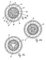
- FIG. 10a represents a section through the output shaft in this plane A between two traction pulleys 61.
- Per toothed belt pulley 61 is a freewheel body 63rd mounted with internal toothing. It can be seen three freewheel teeth 58 arranged symmetrically within the freewheel body 63 and mounted on the multi-tooth axes 23 tilted. The freewheel teeth 58 are in this FIG. 10a shown in a non-engaged state.
- the contact surface B of the freewheeling tooth 58 is "decoupled" at a certain distance from the internal teeth of the freewheel body 63.
- the cut output shaft 8 carries at the abutment surfaces between the output shaft 8 and freewheeling gear 58 small holding magnets 92, which ensure that the freewheel teeth even in case of disturbances from the outside (vibrations, etc.) constantly remain a decoupled state.
- the prerequisite here is, of course, that the freewheel tooth 51 is made of a magnetic material.
- the switching part 87 can be seen in the middle of the figure and shown without cable 76. Also symmetrical to the center are located within the switching member 87, the rectangular magnets 79. Their magnetic field pushes in this configuration, the three freewheel toothed magnet 91 to the outside.
- the multi-tooth axes are preferably made of steel and transmit the torque directly to the output pinion assembly 6. As a result, excessive material stresses are kept out of the output shaft.
- the two-sided negative polarity of the freewheeling toothed magnets 91 and the magnets 79 is within the FIG. 10a represented by a minus sign. This condition off FIG. 10a can be described as "magnetically decoupled".
- FIG. 10b also shows a section through the output shaft in the plane A between two traction pulleys 61. It can be seen here, the three freewheel teeth 58 arranged symmetrically within the freewheel body 63 and mounted on the multi-tooth axes 23 tilted. The freewheel teeth 58 are in this FIG. 10b but shown in a coupled state. The contact surface B of the freewheel tooth 58 is "coupled” in positive connection with the internal toothing of the freewheel body 63. The arranged within the output shaft 8 holding magnets 92 touch the Freewheel teeth in this position not.
- the switching part 87 can be seen in the middle of the figure and shown without cable 76. Also symmetrical to the center are located within the switching member 87, the rectangular magnets 79.
- FIG. 10c also shows a section through the output shaft in the plane A between two traction pulleys 61. It can be seen here, the three freewheel teeth 58 arranged symmetrically within the freewheel body 63 and mounted on the multi-tooth axes 23 tilted. The freewheel teeth 58 are in this FIG. 10c however, just like in FIG. 10a , shown in a disengaged state. The contact surface B of the freewheel tooth 58 is "decoupled” at a distance from the internal toothing of the freewheel body 63. The arranged within the output shaft 8 holding magnets 92 touch the steel made and thus magnetic freewheel teeth 58 and hold them firmly in position.
- the switching part is not below the freewheel teeth 58, but axially displaced within another pulley. This condition off FIG. 10c It can therefore be described as "freely decoupled.” It should be explained in an illustrative manner that these coupling means can in principle be arranged on each shaft of a gearbox, by way of example the coupling means being illustrated on the output shaft.
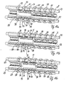
- FIG. 11a provides the output shaft 8 with the 7 clutch means cut longitudinally without the freewheel body 63 and without the pulley 61.
- the already in FIG. 9 described switching control is limited to the representation of the switching part 87, in which the magnets 79 are inserted.
- the polarity of the magnets is represented by a plus and a minus sign.
- at least one component is mounted rotatably or displaceably within a toothing.
- the middle magnet 97 is located with its positive side to the freewheel tooth fixed inserted into the switching part 87.
- the switching part 87 is located in the illustration exactly centered under the engaged freewheel tooth 93.
- the freewheel magnet 91 is directed with its negative pole to the switching part 97 and is thus tightened. Due to the rocker shape of the freewheel teeth thereby the contact surface B from the illustration in FIG. 10a pressed into the internal teeth of the freewheel body, not shown. In this way, a rotationally fixed connection is made between the input shaft and the output shaft by this positive coupling means. Or generally speaking, at least one component in a toothing can assume a positive-locking position within the coupling means.
- FIG. 11b shows the shift from this gear two into gear three.
- the engagement process of gear three is synonymous with the tilting movement of this freewheel tooth 94.
- the switching member 87 during its movement to the right.
- the overlapping magnets 99 already bring about the engagement process of the freewheel tooth 94.
- the freewheel tooth 93 is still in engagement. Since due to the different ratios within the individual gear stages not both freewheel teeth can transmit forces, working at this moment one of the two freewheel teeth 93 and 94 in its freewheeling function us imperceptibly jumps in the internal teeth over the user.
- FIG. 11c shows the completed shift from gear two into gear three. Considering the second freewheel tooth 93 from the left side, it has been pushed out of the negative pole magnet on the switching part of the positive connection of the freewheel body.
- at least one component can assume a position at a distance relative to a toothing.
- the switching member 87 again exactly centered in its locking position under the third freewheel tooth 94.
- the switching process is thus completed.
- FIG. 11 thus shows by way of example that the Novelty advantageous additionally characterized in that at least one component occupies a position at a distance relative to a toothing, after two equally polarized magnetic fields have moved toward each other.
- FIG. 12 shows a gear ratio with a traction means 66 and a pulley 60 for the drive and a pulley 61 for the output.
- the traction means 66 is formed as a toothed belt and the traction pulleys 60 and 61 as a toothed belt pulleys.
- the FIG. 12a shows the gear ratio in the loaded state. It can be seen that the pressure bearings 9 do not touch the traction means in this load state. This prevents a skipping of the toothed belt on the toothed belt pulleys, because an increase in the load leads to an increase in the wrap angle and also to an increased concave curvature of the empty strand.
- FIGS. 12a and 12b areas are hatched shaded, which form additional guides contactless in the immediate vicinity of the toothed belt on the empty strand side and are shaped similar to the outer contour of the toothed belt. These guides prevent the complete emergence of the timing belt from the Toothed belt pulleys and thus prevent damage to the belt by squeezing between the pressure roller and pulley.
Landscapes
- Engineering & Computer Science (AREA)
- Chemical & Material Sciences (AREA)
- Combustion & Propulsion (AREA)
- Transportation (AREA)
- Mechanical Engineering (AREA)
- Devices For Conveying Motion By Means Of Endless Flexible Members (AREA)
Claims (34)
- Transmission à moyen de traction (18) pour véhicules ou pour l'utilisation dans la technique d'entraînement avec un arbre d'entrée (7) monté sur un bâti et un arbre de sortie (8), l'arbre d'entrée (7) et l'arbre de sortie (8) étant guidés hors du bâti, comprenant :entre l'arbre d'entrée (7) et l'arbre de sortie (8) se trouve un rapport de transmission avec des pignons de transmission, lequel est réalisé sous forme de transmission à moyen de traction,tous les pignons de transmission se trouvent constamment en rotation pendant le fonctionnement, le rapport de transmission se trouvant entre l'arbre d'entrée (7) et l'arbre de sortie (8) est réalisé sous forme de transmission à moyen de traction avec une courroie dentée en tant que moyen de traction (66) et avec des poulies de courroie dentée (60, 61) en tant que roues de transmission,caractérisée en ce quela courroie dentée est comprimée sous forme réniforme pendant la rotation sans charge sur les poulies de courroie dentée (60, 61) par au moins un composant (68) et en ce que sous l'action d'une charge cet au moins un composant (68) ne vient pas en contact avec la courroie dentée (66) etla forme réniforme de la courroie dentée (66) pendant la rotation sans charge est formée par une courbure convexe d'un tronçon en charge et par une courbure concave d'un tronçon à vide, etla forme réniforme de la courroie dentée (66) est formée en charge par une forme droite du tronçon en charge et par une courbure concave accrue du tronçon à vide.
- Transmission selon la revendication 1, dans laquelle
les courroies dentées (66) sont renforcées par de l'aramide, du kevlar, des fibres de carbone ou d'autres matériaux fibreux. - Transmission selon la revendication 1 ou 2, dans laquelle les poulies de courroie dentée (60, 61) se trouvent supportées à rotation sur l'arbre d'entrée (7) ou l'arbre de sortie (8), les poulies de courroie dentée (60, 61) pouvant être reliées de manière solidaire en rotation à l'arbre de sortie ou à l'arbre d'entrée (7, 8) par un mécanisme d'accouplement.
- Transmission selon la revendication 3, dans laquelle à l'intérieur du mécanisme d'accouplement est monté au moins un composant déplaçable ou rotatif par rapport à une denture.
- Transmission selon la revendication 3, dans laquelle à l'intérieur du mécanisme d'accouplement au moins un composant peut adopter une position engagée par correspondance géométrique dans une denture.
- Transmission selon la revendication 3, dans laquelle à l'intérieur du mécanisme d'accouplement au moins un composant peut adopter une position à distance par rapport à une denture.
- Transmission selon la revendication 3, dans laquelle au moins un composant à l'intérieur du mécanisme d'accouplement possède les propriétés d'un aimant permanent (79) avec un pôle nord et un pôle sud magnétique.
- Transmission selon la revendication 3, dans laquelle un état du mécanisme d'accouplement est modifie par une modification d'un champ magnétique supplémentaire à l'intérieur ou à proximité immédiate du mécanisme d'accouplement.
- Transmission selon la revendication 2 ou 3, dans laquelle pendant au moins une opération de changement de vitesses, un état d'au moins deux mécanismes d'accouplement est modifié simultanément.
- Transmission selon la revendication 3, dans laquelle au moins un mécanisme d'accouplement peut transmettre seulement des couples dans un sens de rotation.
- Transmission selon la revendication 4, dans laquelle au moins un composant adopte une position à distance d'une denture, après que deux champs magnétiques de polarisation identique se sont déplacés l'un vers l'autre.
- Transmission selon la revendication 4, dans laquelle un mécanisme d'accouplement par engagement par correspondance géométrique est formé par des dents de roue libre (58) qui peuvent s'engager dans une denture.
- Transmission selon la revendication 12, dans laquelle la denture est réalisée sous forme de denture interne.
- Transmission selon la revendication 12, dans laquelle les dents de roue libre (58) sont disposées symétriquement par rapport à la denture.
- Transmission selon la revendication 12, dans laquelle les dents de roue libre (58) sont montées de manière à pouvoir basculer sur des axes en acier (23) à l'intérieur de l'arbre de sortie (8) sur lequel se trouve le mécanisme d'accouplement.
- Transmission selon la revendication 4, dans laquelle au moins un mécanisme d'accouplement est assemblé à partir d'un aimant permanent et d'un composant en acier.
- Transmission selon la revendication 8, dans laquelle on obtient une modification du champ magnétique supplémentaire par un déplacement axial d'aimants permanents le long de l'axe de rotation d'un arbre sur lequel se trouve le mécanisme d'accouplement.
- Transmission selon la revendication 17, dans laquelle un déplacement axial d'aimants permanents est effectué à l'intérieur de l'arbre de sortie qui est creux.
- Transmission selon la revendication 17, dans laquelle le déplacement axial d'aimants permanents est effectué à l'extérieur de l'arbre d'entrée (7).
- Transmission selon la revendication 17, dans laquelle les aimants permanents (79) qui ont été déplacés axialement sont introduits dans un composant coulissant de commande (100).
- Transmission selon la revendication 20, dans laquelle les aimants permanents (79) sont introduits dans une polarité différente dans le composant coulissant de commande (100).
- Transmission selon la revendication 20, dans laquelle un support sur palier (89) se trouve à l'intérieur du composant coulissant de commande (100).
- Transmission selon la revendication 20, dans laquelle le composant coulissant de commande (100) est en liaison avec une courroie dentée pour le mouvement axial.
- Transmission selon la revendication 20, dans laquelle le composant coulissant de commande (100) adopte des points d'encliquetage à l'intérieur de son mouvement axial par rapport à l'arbre de sortie ou à l'arbre d'entrée.
- Transmission selon la revendication 15, dans laquelle une position basculée de la dent de roue libre (58) sur les axes en acier (23) est maintenue par un aimant permanent.
- Transmission selon la revendication 25, dans laquelle l'aimant permanent est introduit dans un arbre sur lequel se trouve le mécanisme d'accouplement.
- Transmission selon la revendication 3, dans laquelle la liaison solidaire en rotation par engagement par correspondance géométrique entre l'arbre d'entrée ou l'arbre de sortie et la poulie de courroie dentée peut être supprimée à l'aide d'énergie qui a été accumulée dans un champ magnétique préalablement au désaccouplement.
- Transmission selon la revendication 8, dans laquelle la modification du champ magnétique supplémentaire est effectuée à l'intérieur ou à proximité immédiate du mécanisme d'accouplement par des électroaimants.
- Transmission selon la revendication 1 ou 2, dans laquelle le bâti des rapports de transmission est réalisé sous forme de boîtier fermé (43).
- Transmission selon la revendication 2, dans laquelle les matériaux fibreux sont gainés avec du polyuréthanne.
- Transmission selon la revendication 1 ou 2, dans laquelle les courroies dentées modifient leur tension de courroie pendant l'opération de changement de vitesses.
- Transmission selon la revendication 1 ou 2, dans laquelle les courroies dentées modifient leur angle d'enveloppement sur la poulie de courroie dentée pendant l'opération de changement de vitesses.
- Transmission selon la revendication 1 ou 2, dans laquelle l'au moins un composant qui presse la courroie dentée dans une forme réniforme, est réalisé sous forme de rouleau.
- Transmission selon la revendication 1 ou 2, dans laquelle des guides supplémentaires se trouve sur le côté du tronçon à vide sans contact et à proximité immédiate des courroies dentées (66) et sont formés de manière similaire au contour extérieur de la courroie dentée.
Applications Claiming Priority (2)
| Application Number | Priority Date | Filing Date | Title |
|---|---|---|---|
| DE102007013443A DE102007013443A1 (de) | 2007-03-21 | 2007-03-21 | Zugmittelgetriebe mit nierenformiger Form der Zugmittel |
| PCT/DE2008/000482 WO2008113340A1 (fr) | 2007-03-21 | 2008-03-20 | Transmission par lien souple réniforme |
Publications (2)
| Publication Number | Publication Date |
|---|---|
| EP2139752A1 EP2139752A1 (fr) | 2010-01-06 |
| EP2139752B1 true EP2139752B1 (fr) | 2012-09-19 |
Family
ID=39535447
Family Applications (1)
| Application Number | Title | Priority Date | Filing Date |
|---|---|---|---|
| EP08715561A Active EP2139752B1 (fr) | 2007-03-21 | 2008-03-20 | Transmission par lien souple reniforme |
Country Status (5)
| Country | Link |
|---|---|
| US (1) | US8308589B2 (fr) |
| EP (1) | EP2139752B1 (fr) |
| CN (1) | CN101668676B (fr) |
| DE (1) | DE102007013443A1 (fr) |
| WO (1) | WO2008113340A1 (fr) |
Families Citing this family (10)
| Publication number | Priority date | Publication date | Assignee | Title |
|---|---|---|---|---|
| WO2009132605A1 (fr) * | 2008-04-30 | 2009-11-05 | Karlheinz Nicolai | Transmission à engrenages multiples à commande magnétique |
| CN102745298B (zh) * | 2012-07-11 | 2015-04-22 | 天津比沃科技有限公司 | 电动自行车的中置驱动系统 |
| DE202014102645U1 (de) * | 2014-06-06 | 2015-09-11 | Kendrion (Markdorf) Gmbh | Drehschwingungsdämpfer sowie Drehschwingungsdämpfersystem |
| US20160084357A1 (en) * | 2014-09-18 | 2016-03-24 | The Gates Corporation | Belt drive with compression span |
| US9541173B2 (en) | 2014-09-18 | 2017-01-10 | Gates Corporation | Belt drive with compression span |
| US9623931B2 (en) * | 2015-03-06 | 2017-04-18 | Shimano Inc. | Bicycle transmission apparatus |
| US9789928B2 (en) * | 2015-03-06 | 2017-10-17 | Shimano Inc. | Bicycle transmission apparatus |
| DE102018008464A1 (de) | 2017-11-02 | 2019-06-27 | Wilfried Donner | Antriebsstrang mit zwei separaten , mittels Zwischengetriebe gekoppelten schaltbaren Getrieben |
| WO2019086064A1 (fr) | 2017-11-02 | 2019-05-09 | Wilfried Donner | Chaîne cinématique comportant deux transmissions commutables séparées pouvant être accouplées au moyen d'une transmission intermédiaire |
| WO2020061624A1 (fr) * | 2018-09-27 | 2020-04-02 | Cape Bouvard Technologies Pty Ltd | Embrayage |
Family Cites Families (19)
| Publication number | Priority date | Publication date | Assignee | Title |
|---|---|---|---|---|
| CH167367A (de) | 1933-03-16 | 1934-02-15 | Signum Ag | Verfahren zur induktiven Übertragung der Stellung eines Streckensignales auf einen fahrenden Zug. |
| US2168332A (en) | 1935-03-21 | 1939-08-08 | Albert C Fischer | Seed planting, seed inoculation, and fertilizer |
| US2168322A (en) * | 1937-01-06 | 1939-08-08 | Butler James Edward | Change speed mechanism for bicycles |
| US4158316A (en) | 1977-09-14 | 1979-06-19 | Strong Grant H | Chain-drive transmission |
| US4955247A (en) | 1988-11-21 | 1990-09-11 | Marshall Ernest H | Transmission |
| US5553510A (en) | 1995-02-27 | 1996-09-10 | Balhorn; Alan C. | Multi-speed transmission |
| US5871412A (en) | 1997-02-04 | 1999-02-16 | Behr America, Inc. | Technical field |
| US6223613B1 (en) | 1997-03-19 | 2001-05-01 | Preload Gearbox Limited | Preload constant mesh gearbox |
| US5924950A (en) | 1997-10-06 | 1999-07-20 | Pusic; Pavo M | Even increment, non-overlapping bicycle transmission |
| JP4197067B2 (ja) * | 1998-10-28 | 2008-12-17 | ヤマハ発動機株式会社 | 車両用エンジンの動力伝達装置 |
| US6146296A (en) | 1998-12-02 | 2000-11-14 | Apostolo; Mauricio C. | Multiple speed transmission for connecting an air conditioner compressor of a vehicle to the engine of the vehicle |
| DE20201787U1 (de) | 2002-02-01 | 2002-06-20 | Munk, Werner, 13355 Berlin | Schaltbares Getriebe zur Anordnung in einem Tretlager |
| US20040067804A1 (en) | 2002-10-04 | 2004-04-08 | Dratewski George J. | Bicycle drive train |
| US20040066017A1 (en) | 2002-10-04 | 2004-04-08 | Dratewski George J. | Bicycle drive train |
| DE10252434B4 (de) | 2002-11-12 | 2004-11-18 | Kirstein, Gerhard, Dipl.-Ing. | Schaltbarer Zahnriemenantrieb |
| DE10339207B4 (de) | 2003-08-21 | 2008-01-10 | Nicolai, Karlheinz, Dipl.-Ing. (TU) | Fahrradrahmen mit integriertem Getriebegehäuse und Getriebegehäuse für einen Fahrradrahmen |
| DE102004045364B4 (de) | 2004-09-15 | 2006-08-03 | Nicolai, Karlheinz, Dipl.-Ing. (TU) | Mehrfachgetriebe für ein Fahrrad |
| TW200739876A (en) | 2005-10-06 | 2007-10-16 | Nxp Bv | Electrostatic discharge protection device |
| DE102007013444A1 (de) * | 2007-03-21 | 2008-09-25 | Karlheinz Nicolai | Mehrfachgetriebe mit magnetischer Ansteuerung |
-
2007
- 2007-03-21 DE DE102007013443A patent/DE102007013443A1/de not_active Withdrawn
-
2008
- 2008-03-20 EP EP08715561A patent/EP2139752B1/fr active Active
- 2008-03-20 US US12/532,080 patent/US8308589B2/en active Active
- 2008-03-20 WO PCT/DE2008/000482 patent/WO2008113340A1/fr not_active Ceased
- 2008-03-20 CN CN200880012752.2A patent/CN101668676B/zh active Active
Also Published As
| Publication number | Publication date |
|---|---|
| WO2008113340A1 (fr) | 2008-09-25 |
| US20100130319A1 (en) | 2010-05-27 |
| EP2139752A1 (fr) | 2010-01-06 |
| CN101668676B (zh) | 2013-01-02 |
| DE102007013443A1 (de) | 2008-09-25 |
| CN101668676A (zh) | 2010-03-10 |
| US8308589B2 (en) | 2012-11-13 |
Similar Documents
| Publication | Publication Date | Title |
|---|---|---|
| EP2139752B1 (fr) | Transmission par lien souple reniforme | |
| DE102007013444A1 (de) | Mehrfachgetriebe mit magnetischer Ansteuerung | |
| DE102004045364B4 (de) | Mehrfachgetriebe für ein Fahrrad | |
| EP3209543B1 (fr) | Mécanisme de transmission réglable à anneau de friction pour véhicule pouvant être mu par la force d'un moteur et/ou d'un pédalier | |
| EP2483142B1 (fr) | Transmission à trois chaines pour vehicule avec electromoteur | |
| DE102011050447B4 (de) | Getriebeeinheit mit einer oder mit zwei Gangstufen, wahlweise für Fahrräder oder für Anhängefahrräder | |
| DE3200276C2 (de) | Allradantrieb für Fahrzeuge | |
| DE4119387C2 (de) | Antriebseinrichtung für ein Kraftfahrzeug | |
| WO2009132605A1 (fr) | Transmission à engrenages multiples à commande magnétique | |
| DE102022108675A1 (de) | Dämpfer für eine Fahrradkomponente | |
| DE3223102A1 (de) | Vierradantrieb fuer fahrzeuge | |
| EP4249361A1 (fr) | Circuit pour bicyclette | |
| DE4027365A1 (de) | Fahrrad mit kombiniertem tret- und motorantrieb | |
| DE202019103283U1 (de) | Antriebseinheit des Elektrofahrrads | |
| DE102017111728A1 (de) | Fahrzeug-Gangschaltung | |
| DE102011088395A1 (de) | Parallelhybridantriebsstrang | |
| DE102014016395B4 (de) | Unter Last schaltbares Getriebe für Fahrzeuge | |
| DE102008045294A1 (de) | Planetengetriebemechanismus für Fahrradschaltgetriebe | |
| DE102018008464A1 (de) | Antriebsstrang mit zwei separaten , mittels Zwischengetriebe gekoppelten schaltbaren Getrieben | |
| EP2298636B9 (fr) | Dispositif de transmission pour un vélo équipé d'un entraînement auxiliaire | |
| DE102008035317A1 (de) | Getriebeeinheit | |
| DE112019007903T5 (de) | Untersetzungsgetriebebaugruppe | |
| DE102021129412B4 (de) | Antriebsstrang mit tretlager- und nabengetriebe | |
| EP4703251A1 (fr) | Bicyclette | |
| DE102024113872A1 (de) | Antriebsvorrichtung für ein Fahrrad mit einem stufenlos verstellbaren Getriebe |
Legal Events
| Date | Code | Title | Description |
|---|---|---|---|
| PUAI | Public reference made under article 153(3) epc to a published international application that has entered the european phase |
Free format text: ORIGINAL CODE: 0009012 |
|
| 17P | Request for examination filed |
Effective date: 20091016 |
|
| AK | Designated contracting states |
Kind code of ref document: A1 Designated state(s): AT BE BG CH CY CZ DE DK EE ES FI FR GB GR HR HU IE IS IT LI LT LU LV MC MT NL NO PL PT RO SE SI SK TR |
|
| RAP1 | Party data changed (applicant data changed or rights of an application transferred) |
Owner name: THE GATES CORPORATION |
|
| 17Q | First examination report despatched |
Effective date: 20100310 |
|
| DAX | Request for extension of the european patent (deleted) | ||
| REG | Reference to a national code |
Ref country code: DE Ref legal event code: R079 Ref document number: 502008008223 Country of ref document: DE Free format text: PREVIOUS MAIN CLASS: B62M0001020000 Ipc: B62M0011060000 |
|
| GRAP | Despatch of communication of intention to grant a patent |
Free format text: ORIGINAL CODE: EPIDOSNIGR1 |
|
| RIC1 | Information provided on ipc code assigned before grant |
Ipc: B62M 11/04 20060101ALI20120210BHEP Ipc: B62M 11/06 20060101AFI20120210BHEP Ipc: B62M 9/04 20060101ALI20120210BHEP |
|
| GRAS | Grant fee paid |
Free format text: ORIGINAL CODE: EPIDOSNIGR3 |
|
| GRAA | (expected) grant |
Free format text: ORIGINAL CODE: 0009210 |
|
| AK | Designated contracting states |
Kind code of ref document: B1 Designated state(s): AT BE BG CH CY CZ DE DK EE ES FI FR GB GR HR HU IE IS IT LI LT LU LV MC MT NL NO PL PT RO SE SI SK TR |
|
| REG | Reference to a national code |
Ref country code: GB Ref legal event code: FG4D Free format text: NOT ENGLISH |
|
| REG | Reference to a national code |
Ref country code: CH Ref legal event code: EP |
|
| REG | Reference to a national code |
Ref country code: IE Ref legal event code: FG4D Free format text: LANGUAGE OF EP DOCUMENT: GERMAN |
|
| REG | Reference to a national code |
Ref country code: AT Ref legal event code: REF Ref document number: 575863 Country of ref document: AT Kind code of ref document: T Effective date: 20121015 |
|
| REG | Reference to a national code |
Ref country code: DE Ref legal event code: R096 Ref document number: 502008008223 Country of ref document: DE Effective date: 20121108 |
|
| PG25 | Lapsed in a contracting state [announced via postgrant information from national office to epo] |
Ref country code: LT Free format text: LAPSE BECAUSE OF FAILURE TO SUBMIT A TRANSLATION OF THE DESCRIPTION OR TO PAY THE FEE WITHIN THE PRESCRIBED TIME-LIMIT Effective date: 20120919 Ref country code: HR Free format text: LAPSE BECAUSE OF FAILURE TO SUBMIT A TRANSLATION OF THE DESCRIPTION OR TO PAY THE FEE WITHIN THE PRESCRIBED TIME-LIMIT Effective date: 20120919 Ref country code: NO Free format text: LAPSE BECAUSE OF FAILURE TO SUBMIT A TRANSLATION OF THE DESCRIPTION OR TO PAY THE FEE WITHIN THE PRESCRIBED TIME-LIMIT Effective date: 20121219 Ref country code: CY Free format text: LAPSE BECAUSE OF FAILURE TO SUBMIT A TRANSLATION OF THE DESCRIPTION OR TO PAY THE FEE WITHIN THE PRESCRIBED TIME-LIMIT Effective date: 20120919 Ref country code: FI Free format text: LAPSE BECAUSE OF FAILURE TO SUBMIT A TRANSLATION OF THE DESCRIPTION OR TO PAY THE FEE WITHIN THE PRESCRIBED TIME-LIMIT Effective date: 20120919 |
|
| REG | Reference to a national code |
Ref country code: NL Ref legal event code: VDEP Effective date: 20120919 |
|
| REG | Reference to a national code |
Ref country code: LT Ref legal event code: MG4D Effective date: 20120919 |
|
| PG25 | Lapsed in a contracting state [announced via postgrant information from national office to epo] |
Ref country code: GR Free format text: LAPSE BECAUSE OF FAILURE TO SUBMIT A TRANSLATION OF THE DESCRIPTION OR TO PAY THE FEE WITHIN THE PRESCRIBED TIME-LIMIT Effective date: 20121220 Ref country code: SI Free format text: LAPSE BECAUSE OF FAILURE TO SUBMIT A TRANSLATION OF THE DESCRIPTION OR TO PAY THE FEE WITHIN THE PRESCRIBED TIME-LIMIT Effective date: 20120919 Ref country code: LV Free format text: LAPSE BECAUSE OF FAILURE TO SUBMIT A TRANSLATION OF THE DESCRIPTION OR TO PAY THE FEE WITHIN THE PRESCRIBED TIME-LIMIT Effective date: 20120919 Ref country code: SE Free format text: LAPSE BECAUSE OF FAILURE TO SUBMIT A TRANSLATION OF THE DESCRIPTION OR TO PAY THE FEE WITHIN THE PRESCRIBED TIME-LIMIT Effective date: 20120919 |
|
| PG25 | Lapsed in a contracting state [announced via postgrant information from national office to epo] |
Ref country code: NL Free format text: LAPSE BECAUSE OF FAILURE TO SUBMIT A TRANSLATION OF THE DESCRIPTION OR TO PAY THE FEE WITHIN THE PRESCRIBED TIME-LIMIT Effective date: 20120919 Ref country code: ES Free format text: LAPSE BECAUSE OF FAILURE TO SUBMIT A TRANSLATION OF THE DESCRIPTION OR TO PAY THE FEE WITHIN THE PRESCRIBED TIME-LIMIT Effective date: 20121230 Ref country code: RO Free format text: LAPSE BECAUSE OF FAILURE TO SUBMIT A TRANSLATION OF THE DESCRIPTION OR TO PAY THE FEE WITHIN THE PRESCRIBED TIME-LIMIT Effective date: 20120919 Ref country code: EE Free format text: LAPSE BECAUSE OF FAILURE TO SUBMIT A TRANSLATION OF THE DESCRIPTION OR TO PAY THE FEE WITHIN THE PRESCRIBED TIME-LIMIT Effective date: 20120919 Ref country code: CZ Free format text: LAPSE BECAUSE OF FAILURE TO SUBMIT A TRANSLATION OF THE DESCRIPTION OR TO PAY THE FEE WITHIN THE PRESCRIBED TIME-LIMIT Effective date: 20120919 Ref country code: IS Free format text: LAPSE BECAUSE OF FAILURE TO SUBMIT A TRANSLATION OF THE DESCRIPTION OR TO PAY THE FEE WITHIN THE PRESCRIBED TIME-LIMIT Effective date: 20130119 |
|
| PG25 | Lapsed in a contracting state [announced via postgrant information from national office to epo] |
Ref country code: PT Free format text: LAPSE BECAUSE OF FAILURE TO SUBMIT A TRANSLATION OF THE DESCRIPTION OR TO PAY THE FEE WITHIN THE PRESCRIBED TIME-LIMIT Effective date: 20130121 Ref country code: SK Free format text: LAPSE BECAUSE OF FAILURE TO SUBMIT A TRANSLATION OF THE DESCRIPTION OR TO PAY THE FEE WITHIN THE PRESCRIBED TIME-LIMIT Effective date: 20120919 Ref country code: PL Free format text: LAPSE BECAUSE OF FAILURE TO SUBMIT A TRANSLATION OF THE DESCRIPTION OR TO PAY THE FEE WITHIN THE PRESCRIBED TIME-LIMIT Effective date: 20120919 |
|
| PLBE | No opposition filed within time limit |
Free format text: ORIGINAL CODE: 0009261 |
|
| STAA | Information on the status of an ep patent application or granted ep patent |
Free format text: STATUS: NO OPPOSITION FILED WITHIN TIME LIMIT |
|
| PG25 | Lapsed in a contracting state [announced via postgrant information from national office to epo] |
Ref country code: DK Free format text: LAPSE BECAUSE OF FAILURE TO SUBMIT A TRANSLATION OF THE DESCRIPTION OR TO PAY THE FEE WITHIN THE PRESCRIBED TIME-LIMIT Effective date: 20120919 Ref country code: BG Free format text: LAPSE BECAUSE OF FAILURE TO SUBMIT A TRANSLATION OF THE DESCRIPTION OR TO PAY THE FEE WITHIN THE PRESCRIBED TIME-LIMIT Effective date: 20121219 |
|
| 26N | No opposition filed |
Effective date: 20130620 |
|
| PG25 | Lapsed in a contracting state [announced via postgrant information from national office to epo] |
Ref country code: IT Free format text: LAPSE BECAUSE OF FAILURE TO SUBMIT A TRANSLATION OF THE DESCRIPTION OR TO PAY THE FEE WITHIN THE PRESCRIBED TIME-LIMIT Effective date: 20120919 |
|
| BERE | Be: lapsed |
Owner name: THE GATES CORP. Effective date: 20130331 |
|
| REG | Reference to a national code |
Ref country code: DE Ref legal event code: R097 Ref document number: 502008008223 Country of ref document: DE Effective date: 20130620 |
|
| PG25 | Lapsed in a contracting state [announced via postgrant information from national office to epo] |
Ref country code: MC Free format text: LAPSE BECAUSE OF NON-PAYMENT OF DUE FEES Effective date: 20130331 |
|
| REG | Reference to a national code |
Ref country code: CH Ref legal event code: PL |
|
| REG | Reference to a national code |
Ref country code: IE Ref legal event code: MM4A |
|
| PG25 | Lapsed in a contracting state [announced via postgrant information from national office to epo] |
Ref country code: CH Free format text: LAPSE BECAUSE OF NON-PAYMENT OF DUE FEES Effective date: 20130331 Ref country code: BE Free format text: LAPSE BECAUSE OF NON-PAYMENT OF DUE FEES Effective date: 20130331 Ref country code: IE Free format text: LAPSE BECAUSE OF NON-PAYMENT OF DUE FEES Effective date: 20130320 Ref country code: LI Free format text: LAPSE BECAUSE OF NON-PAYMENT OF DUE FEES Effective date: 20130331 |
|
| REG | Reference to a national code |
Ref country code: AT Ref legal event code: MM01 Ref document number: 575863 Country of ref document: AT Kind code of ref document: T Effective date: 20130320 |
|
| PG25 | Lapsed in a contracting state [announced via postgrant information from national office to epo] |
Ref country code: MT Free format text: LAPSE BECAUSE OF FAILURE TO SUBMIT A TRANSLATION OF THE DESCRIPTION OR TO PAY THE FEE WITHIN THE PRESCRIBED TIME-LIMIT Effective date: 20120919 |
|
| PG25 | Lapsed in a contracting state [announced via postgrant information from national office to epo] |
Ref country code: AT Free format text: LAPSE BECAUSE OF NON-PAYMENT OF DUE FEES Effective date: 20130320 |
|
| PG25 | Lapsed in a contracting state [announced via postgrant information from national office to epo] |
Ref country code: TR Free format text: LAPSE BECAUSE OF FAILURE TO SUBMIT A TRANSLATION OF THE DESCRIPTION OR TO PAY THE FEE WITHIN THE PRESCRIBED TIME-LIMIT Effective date: 20120919 |
|
| PG25 | Lapsed in a contracting state [announced via postgrant information from national office to epo] |
Ref country code: LU Free format text: LAPSE BECAUSE OF NON-PAYMENT OF DUE FEES Effective date: 20130320 Ref country code: HU Free format text: LAPSE BECAUSE OF FAILURE TO SUBMIT A TRANSLATION OF THE DESCRIPTION OR TO PAY THE FEE WITHIN THE PRESCRIBED TIME-LIMIT; INVALID AB INITIO Effective date: 20080320 |
|
| REG | Reference to a national code |
Ref country code: FR Ref legal event code: PLFP Year of fee payment: 9 |
|
| REG | Reference to a national code |
Ref country code: FR Ref legal event code: PLFP Year of fee payment: 10 |
|
| REG | Reference to a national code |
Ref country code: FR Ref legal event code: PLFP Year of fee payment: 11 |
|
| PGFP | Annual fee paid to national office [announced via postgrant information from national office to epo] |
Ref country code: DE Payment date: 20250218 Year of fee payment: 18 |
|
| PGFP | Annual fee paid to national office [announced via postgrant information from national office to epo] |
Ref country code: FR Payment date: 20250218 Year of fee payment: 18 |
|
| PGFP | Annual fee paid to national office [announced via postgrant information from national office to epo] |
Ref country code: GB Payment date: 20250221 Year of fee payment: 18 |