EP2139706B1 - Amortisseur de vibrations - Google Patents
Amortisseur de vibrations Download PDFInfo
- Publication number
- EP2139706B1 EP2139706B1 EP08716595A EP08716595A EP2139706B1 EP 2139706 B1 EP2139706 B1 EP 2139706B1 EP 08716595 A EP08716595 A EP 08716595A EP 08716595 A EP08716595 A EP 08716595A EP 2139706 B1 EP2139706 B1 EP 2139706B1
- Authority
- EP
- European Patent Office
- Prior art keywords
- cone
- cylinder
- inner cone
- cylinder according
- component
- Prior art date
- Legal status (The legal status is an assumption and is not a legal conclusion. Google has not performed a legal analysis and makes no representation as to the accuracy of the status listed.)
- Not-in-force
Links
- 230000007704 transition Effects 0.000 claims description 3
- 238000009434 installation Methods 0.000 claims description 2
- 238000006073 displacement reaction Methods 0.000 description 2
- 230000002093 peripheral effect Effects 0.000 description 2
- 238000010276 construction Methods 0.000 description 1
- 230000002349 favourable effect Effects 0.000 description 1
- 238000007689 inspection Methods 0.000 description 1
- 238000004519 manufacturing process Methods 0.000 description 1
Images


Classifications
-
- B—PERFORMING OPERATIONS; TRANSPORTING
- B60—VEHICLES IN GENERAL
- B60G—VEHICLE SUSPENSION ARRANGEMENTS
- B60G13/00—Resilient suspensions characterised by arrangement, location or type of vibration dampers
-
- F—MECHANICAL ENGINEERING; LIGHTING; HEATING; WEAPONS; BLASTING
- F16—ENGINEERING ELEMENTS AND UNITS; GENERAL MEASURES FOR PRODUCING AND MAINTAINING EFFECTIVE FUNCTIONING OF MACHINES OR INSTALLATIONS; THERMAL INSULATION IN GENERAL
- F16F—SPRINGS; SHOCK-ABSORBERS; MEANS FOR DAMPING VIBRATION
- F16F9/00—Springs, vibration-dampers, shock-absorbers, or similarly-constructed movement-dampers using a fluid or the equivalent as damping medium
- F16F9/32—Details
- F16F9/3207—Constructional features
- F16F9/3235—Constructional features of cylinders
- F16F9/3242—Constructional features of cylinders of cylinder ends, e.g. caps
-
- F—MECHANICAL ENGINEERING; LIGHTING; HEATING; WEAPONS; BLASTING
- F16—ENGINEERING ELEMENTS AND UNITS; GENERAL MEASURES FOR PRODUCING AND MAINTAINING EFFECTIVE FUNCTIONING OF MACHINES OR INSTALLATIONS; THERMAL INSULATION IN GENERAL
- F16F—SPRINGS; SHOCK-ABSORBERS; MEANS FOR DAMPING VIBRATION
- F16F9/00—Springs, vibration-dampers, shock-absorbers, or similarly-constructed movement-dampers using a fluid or the equivalent as damping medium
- F16F9/32—Details
- F16F9/54—Arrangements for attachment
Definitions
- the invention relates to a cylinder of a vibration damper according to the preamble of patent claim 1.
- a vibration damper with a cylinder tube which has a conically shaped end region on which a wheel carrier with an inner cone by means of a clamping screw is fixed.
- the generic DE 82 32 408 U1 shows a vibration damper with a wheel, which are also clamped over a cone connection.
- an anti-rotation device is used, which ensures a positional orientation of the wheel carrier in the circumferential direction.
- Object of the present invention is to realize a cone connection to a vibration damper, in which the known from the prior art axial positioning problem is solved.
- the object is achieved in that the cone connection has at least two regions in the circumferential direction with a smaller and a larger cone angle.
- the smaller cone angle takes over the function of the frictional connection and the larger cone angle serves as a stop limit.
- the arrangement of the different cone angle in the circumferential direction also provides an anti-rotation device for the component to be fixed.
- To increase the torsional strength of the mounting cone can be designed in cross-section symmetrical to a transverse axis.
- the cylinder may have at least two conical regions arranged axially in series, which interact with two inner conical surfaces of the component to be fixed.
- the radii of the inner cone surfaces are selected such that a tangent to the convex inner cone surfaces tangent extending through a formed at the transition from one to the other spherical inner cone surface contact line and parallel to the central axis.
- the spherical inner cone surface extends over both conical surfaces.
- the wheel carrier can be made very easily.
- the cylinder can be provided with a marking which documents the position of the attachment to the cylinder set during assembly.
- An axial pull-off can be carried out such that the cylinder extends axially through the component to be fixed and a protruding edge of the cylinder is radially deformable.
- the tangent of the smaller cone angle is smaller than the coefficient of friction of a painted metallic surface pairing.
- FIG. 1 shows a partial section of a vibration damper 1, on the cylinder 3, a wheel carrier 4 is fixed as an attachment.
- the cylinder 3 has a fastening cone 5, which enters into a positive connection with an inner cone surface 7 of the wheel carrier 4 in the axial direction.
- the FIGS. 2 and 3 illustrate on the cylinder 3 and the attachment cone that the entire cone connection in the circumferential direction at least two areas 5a; 5b with different sized cone angles ⁇ ; ⁇ .
- a larger circumferential area 5a is designed with a smaller cone angle ⁇ than the second circumferential area 5b. Due to the different cone angles on the mounting cone and on the inner cone results in a positive Vermosêtsthetic between the wheel and the cylinder.
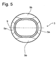
- Fig. 5 to call which has a fastening cone 5 with a cross-sectionally symmetrical to a transverse axis 9, that is that opposite circumferential regions 5a; 5b with a same cone angle a; ⁇ are executed.
- the smaller cone angle a should have a tangent smaller than the coefficient of friction of a painted metallic surface pairing to achieve a tight tapered joint.
- Fig. 1 is additionally shown in the left half of the section, that at at least one of the two components to be connected, in this case the wheel carrier 4, a concave contour profile is executed. This compensates for any dimensional deviations in the diameter and / or cone angle, so that the greatest possible guide length of the wheel carrier 4 is present on the cylinder 3.
- a marking 17 is shown, which documents an adjusted during assembly axial position of the wheel carrier 4 as a component to be fixed on the cylinder 3. If the vibration damper is loaded due to an extreme deflection movement over an intended level, then u. U. the cylinder 3 are pressed into the wheel carrier 4 stronger. This axial displacement can be determined on the marking, so that in a vehicle inspection the overuse of the vibration is recognizable.
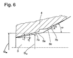
- the Fig. 6 shows a cylinder with at least two axially arranged in series cone portions 5a; 5b, which have a different cone angle ⁇ ; ⁇ .
- the wheel carrier 4 also has two inner cone surfaces 7a arranged in series; 7b with different cone angles ⁇ , ⁇ , the cone regions 5a; 7a on the cylinder 3 and on the wheel carrier 4 with the smaller cone angle form the frictional conical connection and the cone portions 5b; 7b with the larger cone angle hold the axial position of the wheel carrier 4 to the cylinder 3 in a narrower tolerance range.
- the axially overlapping cone angles on the wheel carrier and on the cylinder are designed with a defined deviation.
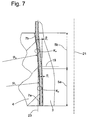
- the Fig. 7 shows a variant on the Fig. 6 building.
- the inner cone surfaces 7a, 7b of the wheel carrier 4 are in the direction of the conical surface 5a; 5b of the cylinder 3 performed crowned and have different radii of curvature R 1 ; R 2 .
- the supporting contact points K P of the inner cone surfaces 7a; 7b are marked annular. At the transition between the two spherical inner cone surfaces 7a; 7b, a contact line 19 is formed.
- the radii of the inner cone surfaces 7a, 7b are selected such that a tangent 23 aligned by the contact line with the inner cone surface 7b and parallel to the central axis 21 of the cylinder 3 runs, so that over the entire course of both inner cone surfaces 7a; 7b there is no undercut.
Landscapes
- Engineering & Computer Science (AREA)
- General Engineering & Computer Science (AREA)
- Mechanical Engineering (AREA)
- Fluid-Damping Devices (AREA)
- Springs (AREA)
Claims (11)
- Cylindre (3) d'un amortisseur de vibrations (1), comprenant un cône de fixation (5, 5a, 5b) sur lequel peut être fixé un composant (4) avec une surface conique interne (7), une liaison de fixation en rotation par engagement par correspondance géométrique agissant entre le cylindre et le composant,
caractérisé en ce que
la liaison conique présente dans la direction périphérique au moins deux régions (5a ; 5b) avec un angle de conicité plus petit et un angle de conicité plus grand (α ; β ; γ ; ϕ). - Cylindre selon la revendication 1,
caractérisé en ce
qu'au moins l'un des deux composants (3 ; 4) à relier présente un cône (7a) avec une allure conique concave. - Cylindre selon la revendication 1,
caractérisé en ce que
le cône de fixation (5a ; 5b) est réalisé en section transversale de manière symétrique par rapport à un axe transversal (9). - Cylindre selon la revendication 1,
caractérisé en ce que
le cylindre (3) présente au moins deux régions coniques (5a ; 5b) disposées axialement en rangée, qui coopèrent avec deux surfaces coniques internes (7 ; 7a ; 7b) du composant (4) à fixer. - Cylindre selon la revendication 4,
caractérisé en ce que
les angles (γ, ϕ) des surfaces coniques internes (7a ; 7b) du composant à fixer (4) s'écartent dans le sens des angles de conicité (α ; β) dans les régions coniques (5a ; 5b) du cylindre (3), en ce qu'un premier angle de conicité interne (γ) est supérieur à l'angle de conicité (α) coopérant avec lui dans la région conique (5a) du cylindre (3), et un deuxième angle de conicité interne (ϕ) est inférieur à un deuxième angle de conicité (β) coopérant avec lui dans la région conique (5b) du cylindre (3), de sorte que les bords espacés au maximum des surfaces coniques internes (7a ; 7b) viennent en appui sur les régions coniques (5a ; 5b) du cylindre (3). - Cylindre selon la revendication 4,
caractérisé en ce que
les surfaces coniques internes (7 ; 7a ; 7b) sont réalisées sous forme bombée dans la direction des régions coniques (5a ; 5b). - Cylindre selon la revendication 6,
caractérisé en ce
qu'une tangente (23) orientée vers les surfaces coniques internes bombées (7b) s'étend à travers une ligne de contact (19) formée par l'une et par l'autre surface conique interne bombée (7a ; 7b) et parallèlement à l'axe médian (21). - Cylindre selon la revendication 6,
caractérisé en ce que
la surface conique interne bombée (7) s'étend sur les deux surfaces coniques (5a ; 5b). - Cylindre selon l'une quelconque des revendications 1 à 8,
caractérisé en ce que
le cylindre (3) est pourvu d'un marquage (17), qui documente la position ajustée lors du montage de la partie rapportée (4) par rapport au cylindre (3) . - Cylindre selon l'une quelconque des revendications 1 à 9,
caractérisé en ce que
le cylindre (3) s'étend axialement à travers le composant à fixer, et un bord saillant (13) du cylindre (3) peut être déformé radialement et forme une fixation axiale contre le retrait (11). - Cylindre selon l'une quelconque des revendications 1 à 10,
caractérisé en ce que
la tangente du plus petit angle de conicité (α) est inférieure au coefficient de friction d'une paire de surfaces métalliques laquées.
Applications Claiming Priority (2)
| Application Number | Priority Date | Filing Date | Title |
|---|---|---|---|
| DE102007015590A DE102007015590B3 (de) | 2007-03-29 | 2007-03-29 | Schwingungsdämpfer |
| PCT/EP2008/002135 WO2008119462A1 (fr) | 2007-03-29 | 2008-03-18 | Amortisseur de vibrations |
Publications (2)
| Publication Number | Publication Date |
|---|---|
| EP2139706A1 EP2139706A1 (fr) | 2010-01-06 |
| EP2139706B1 true EP2139706B1 (fr) | 2012-02-15 |
Family
ID=39469567
Family Applications (1)
| Application Number | Title | Priority Date | Filing Date |
|---|---|---|---|
| EP08716595A Not-in-force EP2139706B1 (fr) | 2007-03-29 | 2008-03-18 | Amortisseur de vibrations |
Country Status (6)
| Country | Link |
|---|---|
| US (1) | US20100111596A1 (fr) |
| EP (1) | EP2139706B1 (fr) |
| KR (1) | KR20100016035A (fr) |
| AT (1) | ATE545531T1 (fr) |
| DE (1) | DE102007015590B3 (fr) |
| WO (1) | WO2008119462A1 (fr) |
Families Citing this family (2)
| Publication number | Priority date | Publication date | Assignee | Title |
|---|---|---|---|---|
| DE102013215602A1 (de) | 2013-08-07 | 2015-02-12 | Bayerische Motoren Werke Aktiengesellschaft | Anordnung für einen Schwingungsdämpfer eines Fahrzeugs |
| CN113833795A (zh) * | 2021-09-30 | 2021-12-24 | 四川宁江山川机械有限责任公司 | 一种通过锥面配合的连杆与上安装座总成 |
Family Cites Families (22)
| Publication number | Priority date | Publication date | Assignee | Title |
|---|---|---|---|---|
| US2367196A (en) * | 1943-10-15 | 1945-01-16 | Standard Telephones Cables Ltd | Locking device for telescoping members |
| US2834081A (en) * | 1955-08-26 | 1958-05-13 | Jr Charles W Stump | Rod fastener |
| US3287040A (en) * | 1964-07-07 | 1966-11-22 | Leo Prager Inc | Telescopic assembly and locking means therefor |
| US3580619A (en) * | 1970-03-06 | 1971-05-25 | Amp Inc | Spring clip |
| US3709575A (en) * | 1971-04-19 | 1973-01-09 | Textron Inc | Shaft locking device |
| US4295753A (en) * | 1977-11-10 | 1981-10-20 | Mcculloch Corporation | Torque transmitting apparatus |
| IT1144176B (it) * | 1981-04-21 | 1986-10-29 | Iao Industrie Riunite Spa | Montante per sospensioni del tipo macpherson per autoveicoli |
| DE8232408U1 (de) * | 1982-11-19 | 1983-03-10 | Fichtel & Sachs Ag, 8720 Schweinfurt | Federbein mit Achsschenkel |
| FR2605914B1 (fr) * | 1986-11-03 | 1988-12-02 | Cegedur | Assemblage par emmanchement a force d'un tube metallique circulaire dans un logement ovale |
| US5090837A (en) * | 1988-10-14 | 1992-02-25 | Lifetime Products, Inc. | Permanent fastener-free pole joint |
| DE4034129C1 (fr) * | 1990-10-26 | 1992-05-07 | Gkn Cardantec International Gesellschaft Fuer Antriebstechnik Mbh, 4300 Essen, De | |
| JP2709269B2 (ja) * | 1994-06-13 | 1998-02-04 | 株式会社椿本チエイン | 軸と回転体の摩擦式締結具 |
| US5632684A (en) * | 1995-10-24 | 1997-05-27 | Xerox Corporation | Stepped shaft assembly |
| GB2309947B (en) * | 1996-02-08 | 2000-04-19 | Rover Group | A vehicle suspension |
| US5993102A (en) * | 1996-12-02 | 1999-11-30 | Tsubakimoto Chain Co. | Rotary body fixing device |
| DE19815215B4 (de) * | 1997-06-18 | 2014-10-16 | Zf Friedrichshafen Ag | Federbein mit Achsschenkel |
| JP2000158270A (ja) * | 1998-09-25 | 2000-06-13 | Seiwa Seiki Kk | ツールホルダ |
| JP3587705B2 (ja) * | 1998-11-25 | 2004-11-10 | アルプス電気株式会社 | 電気部品の結合構造 |
| US6779955B2 (en) * | 2001-05-31 | 2004-08-24 | Evgeny I. Rivin | Mechanical contact connection |
| US7455471B2 (en) * | 2004-05-19 | 2008-11-25 | Eric M. Gawehn | Eccentric conical fastening system |
| US7318650B2 (en) * | 2005-06-01 | 2008-01-15 | Lang-Mekra North America, Llc | Tapered tube lock connector for a vehicle mirror mounting assembly |
| US7765752B2 (en) * | 2008-02-20 | 2010-08-03 | Hayes Specialty Machining, Ltd. | Anchor system with substantially longitudinally equal wedge compression |
-
2007
- 2007-03-29 DE DE102007015590A patent/DE102007015590B3/de not_active Expired - Fee Related
-
2008
- 2008-03-18 EP EP08716595A patent/EP2139706B1/fr not_active Not-in-force
- 2008-03-18 AT AT08716595T patent/ATE545531T1/de active
- 2008-03-18 US US12/593,757 patent/US20100111596A1/en not_active Abandoned
- 2008-03-18 WO PCT/EP2008/002135 patent/WO2008119462A1/fr not_active Ceased
- 2008-03-18 KR KR1020097022639A patent/KR20100016035A/ko not_active Ceased
Also Published As
| Publication number | Publication date |
|---|---|
| DE102007015590B3 (de) | 2008-10-02 |
| US20100111596A1 (en) | 2010-05-06 |
| KR20100016035A (ko) | 2010-02-12 |
| EP2139706A1 (fr) | 2010-01-06 |
| ATE545531T1 (de) | 2012-03-15 |
| WO2008119462A1 (fr) | 2008-10-09 |
Similar Documents
| Publication | Publication Date | Title |
|---|---|---|
| EP2414180B1 (fr) | Articulation elastomere | |
| EP3036443B1 (fr) | Procédé pour assembler des pièces et module correspondant | |
| EP1600679A1 (fr) | Dispositif de raccordement en plastique pour fixer un tuyau souple | |
| DE19815215B4 (de) | Federbein mit Achsschenkel | |
| EP2181275A1 (fr) | Tube protecteur pour ensemble piston-cylindre | |
| DE102004049968A1 (de) | Zapfenkäfig, insbesondere für größere Radial- oder Axialrollenlager | |
| EP2139706B1 (fr) | Amortisseur de vibrations | |
| EP3277977B1 (fr) | Amortisseur axial | |
| EP4244517B1 (fr) | Unité de connexion de fluide | |
| DE102007016742A1 (de) | Gelenklager, insbesondere an einem Drehgelenk zwischen einem Vorderwagen und Hinterwagen eines Gelenkbusses | |
| EP3532738B1 (fr) | Raccord enfichable annulaire et procédé de fabrication d'un raccord entre des composants à l'aide du raccord enfichable annulaire | |
| DE102016205916A1 (de) | Drehstabfeder | |
| DE102010052589A1 (de) | Befestigung eines Geberzylinders an einer Fahrzeugwand | |
| WO2011110457A1 (fr) | Élément de blocage axial de forme annulaire | |
| DE102016103306B4 (de) | Achssystem | |
| EP3623251B1 (fr) | Dispositif stabilisateur pour véhicules ferroviaires, en particulier stabilisateur de roulis | |
| EP1384923B1 (fr) | Joint d'étanchéité oour un dispositif de rattrapage de jeu axial d'un arbre articulé | |
| DE102014224130A1 (de) | Lageranordnung | |
| WO2018077665A1 (fr) | Système de fixation | |
| DE102017107583A1 (de) | Rolle | |
| DE4430922B4 (de) | Arretierelement, versehen mit Maßnahmen zur Lagesicherung, die am Käfig sowie am Führungsteil vorgesehen sind | |
| EP4080069B1 (fr) | Système de fixation | |
| DE102005002231B4 (de) | Federteller für einen Schwingungsdämpfer | |
| DE102018006341A1 (de) | Bremsbelaghalteelement für eine Fahrzeugscheibenbremse | |
| AT402656B (de) | Hydraulischer arbeitszylinder hydraulischer arbeitszylinder |
Legal Events
| Date | Code | Title | Description |
|---|---|---|---|
| PUAI | Public reference made under article 153(3) epc to a published international application that has entered the european phase |
Free format text: ORIGINAL CODE: 0009012 |
|
| 17P | Request for examination filed |
Effective date: 20090907 |
|
| AK | Designated contracting states |
Kind code of ref document: A1 Designated state(s): AT BE BG CH CY CZ DE DK EE ES FI FR GB GR HR HU IE IS IT LI LT LU LV MC MT NL NO PL PT RO SE SI SK TR |
|
| DAX | Request for extension of the european patent (deleted) | ||
| GRAP | Despatch of communication of intention to grant a patent |
Free format text: ORIGINAL CODE: EPIDOSNIGR1 |
|
| GRAS | Grant fee paid |
Free format text: ORIGINAL CODE: EPIDOSNIGR3 |
|
| GRAA | (expected) grant |
Free format text: ORIGINAL CODE: 0009210 |
|
| AK | Designated contracting states |
Kind code of ref document: B1 Designated state(s): AT BE BG CH CY CZ DE DK EE ES FI FR GB GR HR HU IE IS IT LI LT LU LV MC MT NL NO PL PT RO SE SI SK TR |
|
| REG | Reference to a national code |
Ref country code: GB Ref legal event code: FG4D Free format text: NOT ENGLISH Ref country code: CH Ref legal event code: EP |
|
| REG | Reference to a national code |
Ref country code: IE Ref legal event code: FG4D Free format text: LANGUAGE OF EP DOCUMENT: GERMAN |
|
| REG | Reference to a national code |
Ref country code: AT Ref legal event code: REF Ref document number: 545531 Country of ref document: AT Kind code of ref document: T Effective date: 20120315 |
|
| REG | Reference to a national code |
Ref country code: DE Ref legal event code: R096 Ref document number: 502008006413 Country of ref document: DE Effective date: 20120412 |
|
| REG | Reference to a national code |
Ref country code: NL Ref legal event code: VDEP Effective date: 20120215 |
|
| LTIE | Lt: invalidation of european patent or patent extension |
Effective date: 20120215 |
|
| PG25 | Lapsed in a contracting state [announced via postgrant information from national office to epo] |
Ref country code: NO Free format text: LAPSE BECAUSE OF FAILURE TO SUBMIT A TRANSLATION OF THE DESCRIPTION OR TO PAY THE FEE WITHIN THE PRESCRIBED TIME-LIMIT Effective date: 20120515 Ref country code: HR Free format text: LAPSE BECAUSE OF FAILURE TO SUBMIT A TRANSLATION OF THE DESCRIPTION OR TO PAY THE FEE WITHIN THE PRESCRIBED TIME-LIMIT Effective date: 20120215 Ref country code: IS Free format text: LAPSE BECAUSE OF FAILURE TO SUBMIT A TRANSLATION OF THE DESCRIPTION OR TO PAY THE FEE WITHIN THE PRESCRIBED TIME-LIMIT Effective date: 20120615 Ref country code: LT Free format text: LAPSE BECAUSE OF FAILURE TO SUBMIT A TRANSLATION OF THE DESCRIPTION OR TO PAY THE FEE WITHIN THE PRESCRIBED TIME-LIMIT Effective date: 20120215 Ref country code: NL Free format text: LAPSE BECAUSE OF FAILURE TO SUBMIT A TRANSLATION OF THE DESCRIPTION OR TO PAY THE FEE WITHIN THE PRESCRIBED TIME-LIMIT Effective date: 20120215 |
|
| PG25 | Lapsed in a contracting state [announced via postgrant information from national office to epo] |
Ref country code: GR Free format text: LAPSE BECAUSE OF FAILURE TO SUBMIT A TRANSLATION OF THE DESCRIPTION OR TO PAY THE FEE WITHIN THE PRESCRIBED TIME-LIMIT Effective date: 20120516 Ref country code: LV Free format text: LAPSE BECAUSE OF FAILURE TO SUBMIT A TRANSLATION OF THE DESCRIPTION OR TO PAY THE FEE WITHIN THE PRESCRIBED TIME-LIMIT Effective date: 20120215 Ref country code: PL Free format text: LAPSE BECAUSE OF FAILURE TO SUBMIT A TRANSLATION OF THE DESCRIPTION OR TO PAY THE FEE WITHIN THE PRESCRIBED TIME-LIMIT Effective date: 20120215 Ref country code: FI Free format text: LAPSE BECAUSE OF FAILURE TO SUBMIT A TRANSLATION OF THE DESCRIPTION OR TO PAY THE FEE WITHIN THE PRESCRIBED TIME-LIMIT Effective date: 20120215 Ref country code: PT Free format text: LAPSE BECAUSE OF FAILURE TO SUBMIT A TRANSLATION OF THE DESCRIPTION OR TO PAY THE FEE WITHIN THE PRESCRIBED TIME-LIMIT Effective date: 20120615 |
|
| REG | Reference to a national code |
Ref country code: IE Ref legal event code: FD4D |
|
| PG25 | Lapsed in a contracting state [announced via postgrant information from national office to epo] |
Ref country code: CY Free format text: LAPSE BECAUSE OF FAILURE TO SUBMIT A TRANSLATION OF THE DESCRIPTION OR TO PAY THE FEE WITHIN THE PRESCRIBED TIME-LIMIT Effective date: 20120215 |
|
| BERE | Be: lapsed |
Owner name: ZF FRIEDRICHSHAFEN A.G. Effective date: 20120331 |
|
| PG25 | Lapsed in a contracting state [announced via postgrant information from national office to epo] |
Ref country code: SI Free format text: LAPSE BECAUSE OF FAILURE TO SUBMIT A TRANSLATION OF THE DESCRIPTION OR TO PAY THE FEE WITHIN THE PRESCRIBED TIME-LIMIT Effective date: 20120215 Ref country code: RO Free format text: LAPSE BECAUSE OF FAILURE TO SUBMIT A TRANSLATION OF THE DESCRIPTION OR TO PAY THE FEE WITHIN THE PRESCRIBED TIME-LIMIT Effective date: 20120215 Ref country code: CZ Free format text: LAPSE BECAUSE OF FAILURE TO SUBMIT A TRANSLATION OF THE DESCRIPTION OR TO PAY THE FEE WITHIN THE PRESCRIBED TIME-LIMIT Effective date: 20120215 Ref country code: MC Free format text: LAPSE BECAUSE OF NON-PAYMENT OF DUE FEES Effective date: 20120331 Ref country code: DK Free format text: LAPSE BECAUSE OF FAILURE TO SUBMIT A TRANSLATION OF THE DESCRIPTION OR TO PAY THE FEE WITHIN THE PRESCRIBED TIME-LIMIT Effective date: 20120215 Ref country code: EE Free format text: LAPSE BECAUSE OF FAILURE TO SUBMIT A TRANSLATION OF THE DESCRIPTION OR TO PAY THE FEE WITHIN THE PRESCRIBED TIME-LIMIT Effective date: 20120215 Ref country code: IE Free format text: LAPSE BECAUSE OF FAILURE TO SUBMIT A TRANSLATION OF THE DESCRIPTION OR TO PAY THE FEE WITHIN THE PRESCRIBED TIME-LIMIT Effective date: 20120215 Ref country code: SE Free format text: LAPSE BECAUSE OF FAILURE TO SUBMIT A TRANSLATION OF THE DESCRIPTION OR TO PAY THE FEE WITHIN THE PRESCRIBED TIME-LIMIT Effective date: 20120215 |
|
| REG | Reference to a national code |
Ref country code: CH Ref legal event code: PL |
|
| PG25 | Lapsed in a contracting state [announced via postgrant information from national office to epo] |
Ref country code: SK Free format text: LAPSE BECAUSE OF FAILURE TO SUBMIT A TRANSLATION OF THE DESCRIPTION OR TO PAY THE FEE WITHIN THE PRESCRIBED TIME-LIMIT Effective date: 20120215 Ref country code: IT Free format text: LAPSE BECAUSE OF FAILURE TO SUBMIT A TRANSLATION OF THE DESCRIPTION OR TO PAY THE FEE WITHIN THE PRESCRIBED TIME-LIMIT Effective date: 20120215 |
|
| PLBE | No opposition filed within time limit |
Free format text: ORIGINAL CODE: 0009261 |
|
| STAA | Information on the status of an ep patent application or granted ep patent |
Free format text: STATUS: NO OPPOSITION FILED WITHIN TIME LIMIT |
|
| 26N | No opposition filed |
Effective date: 20121116 |
|
| GBPC | Gb: european patent ceased through non-payment of renewal fee |
Effective date: 20120515 |
|
| PG25 | Lapsed in a contracting state [announced via postgrant information from national office to epo] |
Ref country code: CH Free format text: LAPSE BECAUSE OF NON-PAYMENT OF DUE FEES Effective date: 20120331 Ref country code: LI Free format text: LAPSE BECAUSE OF NON-PAYMENT OF DUE FEES Effective date: 20120331 Ref country code: BE Free format text: LAPSE BECAUSE OF NON-PAYMENT OF DUE FEES Effective date: 20120331 |
|
| REG | Reference to a national code |
Ref country code: DE Ref legal event code: R097 Ref document number: 502008006413 Country of ref document: DE Effective date: 20121116 |
|
| PG25 | Lapsed in a contracting state [announced via postgrant information from national office to epo] |
Ref country code: GB Free format text: LAPSE BECAUSE OF NON-PAYMENT OF DUE FEES Effective date: 20120515 Ref country code: ES Free format text: LAPSE BECAUSE OF FAILURE TO SUBMIT A TRANSLATION OF THE DESCRIPTION OR TO PAY THE FEE WITHIN THE PRESCRIBED TIME-LIMIT Effective date: 20120526 |
|
| PG25 | Lapsed in a contracting state [announced via postgrant information from national office to epo] |
Ref country code: MT Free format text: LAPSE BECAUSE OF FAILURE TO SUBMIT A TRANSLATION OF THE DESCRIPTION OR TO PAY THE FEE WITHIN THE PRESCRIBED TIME-LIMIT Effective date: 20120215 Ref country code: BG Free format text: LAPSE BECAUSE OF FAILURE TO SUBMIT A TRANSLATION OF THE DESCRIPTION OR TO PAY THE FEE WITHIN THE PRESCRIBED TIME-LIMIT Effective date: 20120515 |
|
| PG25 | Lapsed in a contracting state [announced via postgrant information from national office to epo] |
Ref country code: TR Free format text: LAPSE BECAUSE OF FAILURE TO SUBMIT A TRANSLATION OF THE DESCRIPTION OR TO PAY THE FEE WITHIN THE PRESCRIBED TIME-LIMIT Effective date: 20120215 |
|
| REG | Reference to a national code |
Ref country code: AT Ref legal event code: MM01 Ref document number: 545531 Country of ref document: AT Kind code of ref document: T Effective date: 20130318 |
|
| PG25 | Lapsed in a contracting state [announced via postgrant information from national office to epo] |
Ref country code: LU Free format text: LAPSE BECAUSE OF NON-PAYMENT OF DUE FEES Effective date: 20120318 |
|
| PGFP | Annual fee paid to national office [announced via postgrant information from national office to epo] |
Ref country code: FR Payment date: 20140311 Year of fee payment: 7 |
|
| PG25 | Lapsed in a contracting state [announced via postgrant information from national office to epo] |
Ref country code: HU Free format text: LAPSE BECAUSE OF FAILURE TO SUBMIT A TRANSLATION OF THE DESCRIPTION OR TO PAY THE FEE WITHIN THE PRESCRIBED TIME-LIMIT Effective date: 20080318 |
|
| PG25 | Lapsed in a contracting state [announced via postgrant information from national office to epo] |
Ref country code: AT Free format text: LAPSE BECAUSE OF NON-PAYMENT OF DUE FEES Effective date: 20130318 |
|
| PGFP | Annual fee paid to national office [announced via postgrant information from national office to epo] |
Ref country code: DE Payment date: 20150310 Year of fee payment: 8 |
|
| REG | Reference to a national code |
Ref country code: FR Ref legal event code: ST Effective date: 20151130 |
|
| PG25 | Lapsed in a contracting state [announced via postgrant information from national office to epo] |
Ref country code: FR Free format text: LAPSE BECAUSE OF NON-PAYMENT OF DUE FEES Effective date: 20150331 |
|
| REG | Reference to a national code |
Ref country code: DE Ref legal event code: R119 Ref document number: 502008006413 Country of ref document: DE |
|
| PG25 | Lapsed in a contracting state [announced via postgrant information from national office to epo] |
Ref country code: DE Free format text: LAPSE BECAUSE OF NON-PAYMENT OF DUE FEES Effective date: 20161001 |