EP2139706B1 - Vibration damper - Google Patents
Vibration damper Download PDFInfo
- Publication number
- EP2139706B1 EP2139706B1 EP08716595A EP08716595A EP2139706B1 EP 2139706 B1 EP2139706 B1 EP 2139706B1 EP 08716595 A EP08716595 A EP 08716595A EP 08716595 A EP08716595 A EP 08716595A EP 2139706 B1 EP2139706 B1 EP 2139706B1
- Authority
- EP
- European Patent Office
- Prior art keywords
- cone
- cylinder
- inner cone
- cylinder according
- component
- Prior art date
- Legal status (The legal status is an assumption and is not a legal conclusion. Google has not performed a legal analysis and makes no representation as to the accuracy of the status listed.)
- Not-in-force
Links
- 230000007704 transition Effects 0.000 claims description 3
- 238000009434 installation Methods 0.000 claims description 2
- 238000006073 displacement reaction Methods 0.000 description 2
- 230000002093 peripheral effect Effects 0.000 description 2
- 238000010276 construction Methods 0.000 description 1
- 230000002349 favourable effect Effects 0.000 description 1
- 238000007689 inspection Methods 0.000 description 1
- 238000004519 manufacturing process Methods 0.000 description 1
Images



Classifications
-
- B—PERFORMING OPERATIONS; TRANSPORTING
- B60—VEHICLES IN GENERAL
- B60G—VEHICLE SUSPENSION ARRANGEMENTS
- B60G13/00—Resilient suspensions characterised by arrangement, location or type of vibration dampers
-
- F—MECHANICAL ENGINEERING; LIGHTING; HEATING; WEAPONS; BLASTING
- F16—ENGINEERING ELEMENTS AND UNITS; GENERAL MEASURES FOR PRODUCING AND MAINTAINING EFFECTIVE FUNCTIONING OF MACHINES OR INSTALLATIONS; THERMAL INSULATION IN GENERAL
- F16F—SPRINGS; SHOCK-ABSORBERS; MEANS FOR DAMPING VIBRATION
- F16F9/00—Springs, vibration-dampers, shock-absorbers, or similarly-constructed movement-dampers using a fluid or the equivalent as damping medium
- F16F9/32—Details
- F16F9/3207—Constructional features
- F16F9/3235—Constructional features of cylinders
- F16F9/3242—Constructional features of cylinders of cylinder ends, e.g. caps
-
- F—MECHANICAL ENGINEERING; LIGHTING; HEATING; WEAPONS; BLASTING
- F16—ENGINEERING ELEMENTS AND UNITS; GENERAL MEASURES FOR PRODUCING AND MAINTAINING EFFECTIVE FUNCTIONING OF MACHINES OR INSTALLATIONS; THERMAL INSULATION IN GENERAL
- F16F—SPRINGS; SHOCK-ABSORBERS; MEANS FOR DAMPING VIBRATION
- F16F9/00—Springs, vibration-dampers, shock-absorbers, or similarly-constructed movement-dampers using a fluid or the equivalent as damping medium
- F16F9/32—Details
-
- F—MECHANICAL ENGINEERING; LIGHTING; HEATING; WEAPONS; BLASTING
- F16—ENGINEERING ELEMENTS AND UNITS; GENERAL MEASURES FOR PRODUCING AND MAINTAINING EFFECTIVE FUNCTIONING OF MACHINES OR INSTALLATIONS; THERMAL INSULATION IN GENERAL
- F16F—SPRINGS; SHOCK-ABSORBERS; MEANS FOR DAMPING VIBRATION
- F16F9/00—Springs, vibration-dampers, shock-absorbers, or similarly-constructed movement-dampers using a fluid or the equivalent as damping medium
- F16F9/32—Details
- F16F9/54—Arrangements for attachment
Definitions
- the invention relates to a cylinder of a vibration damper according to the preamble of patent claim 1.
- a vibration damper with a cylinder tube which has a conically shaped end region on which a wheel carrier with an inner cone by means of a clamping screw is fixed.
- the generic DE 82 32 408 U1 shows a vibration damper with a wheel, which are also clamped over a cone connection.
- an anti-rotation device is used, which ensures a positional orientation of the wheel carrier in the circumferential direction.
- Object of the present invention is to realize a cone connection to a vibration damper, in which the known from the prior art axial positioning problem is solved.
- the object is achieved in that the cone connection has at least two regions in the circumferential direction with a smaller and a larger cone angle.
- the smaller cone angle takes over the function of the frictional connection and the larger cone angle serves as a stop limit.
- the arrangement of the different cone angle in the circumferential direction also provides an anti-rotation device for the component to be fixed.
- To increase the torsional strength of the mounting cone can be designed in cross-section symmetrical to a transverse axis.
- the cylinder may have at least two conical regions arranged axially in series, which interact with two inner conical surfaces of the component to be fixed.
- the radii of the inner cone surfaces are selected such that a tangent to the convex inner cone surfaces tangent extending through a formed at the transition from one to the other spherical inner cone surface contact line and parallel to the central axis.
- the spherical inner cone surface extends over both conical surfaces.
- the wheel carrier can be made very easily.
- the cylinder can be provided with a marking which documents the position of the attachment to the cylinder set during assembly.
- An axial pull-off can be carried out such that the cylinder extends axially through the component to be fixed and a protruding edge of the cylinder is radially deformable.
- the tangent of the smaller cone angle is smaller than the coefficient of friction of a painted metallic surface pairing.
- FIG. 1 shows a partial section of a vibration damper 1, on the cylinder 3, a wheel carrier 4 is fixed as an attachment.
- the cylinder 3 has a fastening cone 5, which enters into a positive connection with an inner cone surface 7 of the wheel carrier 4 in the axial direction.
- the FIGS. 2 and 3 illustrate on the cylinder 3 and the attachment cone that the entire cone connection in the circumferential direction at least two areas 5a; 5b with different sized cone angles ⁇ ; ⁇ .
- a larger circumferential area 5a is designed with a smaller cone angle ⁇ than the second circumferential area 5b. Due to the different cone angles on the mounting cone and on the inner cone results in a positive Vermosêtsthetic between the wheel and the cylinder.
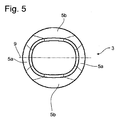
- Fig. 5 to call which has a fastening cone 5 with a cross-sectionally symmetrical to a transverse axis 9, that is that opposite circumferential regions 5a; 5b with a same cone angle a; ⁇ are executed.
- the smaller cone angle a should have a tangent smaller than the coefficient of friction of a painted metallic surface pairing to achieve a tight tapered joint.
- Fig. 1 is additionally shown in the left half of the section, that at at least one of the two components to be connected, in this case the wheel carrier 4, a concave contour profile is executed. This compensates for any dimensional deviations in the diameter and / or cone angle, so that the greatest possible guide length of the wheel carrier 4 is present on the cylinder 3.
- a marking 17 is shown, which documents an adjusted during assembly axial position of the wheel carrier 4 as a component to be fixed on the cylinder 3. If the vibration damper is loaded due to an extreme deflection movement over an intended level, then u. U. the cylinder 3 are pressed into the wheel carrier 4 stronger. This axial displacement can be determined on the marking, so that in a vehicle inspection the overuse of the vibration is recognizable.
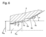
- the Fig. 6 shows a cylinder with at least two axially arranged in series cone portions 5a; 5b, which have a different cone angle ⁇ ; ⁇ .
- the wheel carrier 4 also has two inner cone surfaces 7a arranged in series; 7b with different cone angles ⁇ , ⁇ , the cone regions 5a; 7a on the cylinder 3 and on the wheel carrier 4 with the smaller cone angle form the frictional conical connection and the cone portions 5b; 7b with the larger cone angle hold the axial position of the wheel carrier 4 to the cylinder 3 in a narrower tolerance range.
- the axially overlapping cone angles on the wheel carrier and on the cylinder are designed with a defined deviation.
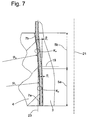
- the Fig. 7 shows a variant on the Fig. 6 building.
- the inner cone surfaces 7a, 7b of the wheel carrier 4 are in the direction of the conical surface 5a; 5b of the cylinder 3 performed crowned and have different radii of curvature R 1 ; R 2 .
- the supporting contact points K P of the inner cone surfaces 7a; 7b are marked annular. At the transition between the two spherical inner cone surfaces 7a; 7b, a contact line 19 is formed.
- the radii of the inner cone surfaces 7a, 7b are selected such that a tangent 23 aligned by the contact line with the inner cone surface 7b and parallel to the central axis 21 of the cylinder 3 runs, so that over the entire course of both inner cone surfaces 7a; 7b there is no undercut.
Landscapes
- Engineering & Computer Science (AREA)
- General Engineering & Computer Science (AREA)
- Mechanical Engineering (AREA)
- Fluid-Damping Devices (AREA)
- Springs (AREA)
Abstract
Description
Die Erfindung betrifft einen Zylinder eines Schwingungsdämpfers gemäß dem Oberbegriff von Patentanspruch 1.The invention relates to a cylinder of a vibration damper according to the preamble of
Aus der
Die gattungsbildende
Ein generelles Problem einer Konusverbindung besteht darin, dass schon geringste Durchmesserabweichungen zu einer deutlich axialen Verschiebung des Radträgers auf dem Zylinder führen, da der Konuswinkel vergleichsweise klein ausgeführt wird. Damit können definierte Einbaumaße des Schwingungsdämpfers nicht eingehalten werden.A general problem of a cone connection is that even the smallest diameter deviations lead to a significant axial displacement of the wheel carrier on the cylinder, since the cone angle is made relatively small. Thus, defined installation dimensions of the vibration damper can not be met.
Eine auf dem ersten Blick naheliegende Lösung könnte darin gesehen werden, dass man einen einfachen Axialanschlag verwendet, wie er beispielsweise in der
Aufgabe der vorliegenden Erfindung ist es, eine Konusverbindung an einem Schwingungsdämpfer zu realisieren, bei der das aus dem Stand der Technik bekannte axiale Positionierungsproblem behoben ist.Object of the present invention is to realize a cone connection to a vibration damper, in which the known from the prior art axial positioning problem is solved.
Erfindungsgemäß wird die Aufgabe dadurch gelöst, dass die Konusverbindung in Umfangsrichtung mindestens zwei Bereiche mit einem kleineren und einem größeren Konuswinkel aufweist.According to the invention, the object is achieved in that the cone connection has at least two regions in the circumferential direction with a smaller and a larger cone angle.
Der kleinere Konuswinkel übernimmt die Funktion der Reibschlussverbindung und der größere Konuswinkel dient als Anschlagbegrenzung. Durch die Anordnung der unterschiedlichen Konuswinkel in Umfangsrichtung erhält man auch eine Verdrehsicherung für das zu fixierende Bauteil.The smaller cone angle takes over the function of the frictional connection and the larger cone angle serves as a stop limit. The arrangement of the different cone angle in the circumferential direction also provides an anti-rotation device for the component to be fixed.
Um eine möglichst optimale wirksame Führungslänge des zu fixierenden Bauteils auf dem Zylinder zu erreichen ist vorgesehen, dass mindestens eines der beiden zu verbindenden Bauteile einen konkaven Konusverlauf aufweist.In order to achieve the best possible effective guide length of the component to be fixed on the cylinder, it is provided that at least one of the two components to be connected has a concave conical profile.
Zur Steigerung der Verdrehfestigkeit kann der Befestigungskonus im Querschnitt symmetrisch zu einer Querachse ausgeführt sein.To increase the torsional strength of the mounting cone can be designed in cross-section symmetrical to a transverse axis.
Alternativ kann der Zylinder mindestens zwei axial in Reihe angeordnete Konusbereiche aufweisen, die mit zwei Innenkonusflächen des zu fixierenden Bauteils zusammenwirken.Alternatively, the cylinder may have at least two conical regions arranged axially in series, which interact with two inner conical surfaces of the component to be fixed.
Im Hinblick auf eine möglichst spielfreie und winkelgetreue Befestigung sind die Winkel der Innenkonusflächen des zu fixierenden Bauteils und die Konusbereiche des Zylinders geringfügig unterschiedlich ausgeführt. So weichen die Winkel der Innenkonusflächen des zu fixierenden Bauteils in dem Sinn von den Konusbereichen des Zylinders ab, dass ein erster Innenkonuswinkel größer ist als der damit zusammenwirkende Konuswinkel im Konusbereich des Zylinders und ein zweiter Innenkonuswinkel kleiner ist als ein damit zusammenwirkender zweiter Konuswinkel im Konusbereich des Zylinders, so dass die maximal beabstandeten Ränder der Innenkonusflächen auf den Konusbereichen des Zylinders zur Anlage kommen.With regard to a possible backlash-free and true to angle mounting the angle of the inner cone surfaces of the component to be fixed and the cone portions of the cylinder are made slightly different. Thus, the angles of the inner cone surfaces of the component to be fixed differ from the cone regions of the cylinder in the sense that a first inner cone angle is greater than the cooperating cone angle in the cone region of the cylinder and a second inner cone angle is smaller than a second cooperating therewith Cone angle in the cone region of the cylinder, so that the maximum spaced edges of the inner cone surfaces come to rest on the cone portions of the cylinder.
Des Weiteren besteht die Möglichkeit, dass die Innenkonusflächen in Richtung der Konusbereiche ballig ausgeführt sind.Furthermore, there is the possibility that the inner cone surfaces are crowned in the direction of the cone regions.
Um eine Hinterschneidung, d. h. eine Durchmesserweiterung zwischen den Innenkonusflächen zu vermeiden, sind die Radien der Innenkonusflächen derart gewählt, dass eine zur balligen Innenkonusflächen ausgerichtete Tangente durch eine am Übergang von der einen auf die andere ballige Innenkonusfläche gebildete Berührlinie und parallel zur Mittelachse verläuft.To an undercut, d. H. To avoid a diameter expansion between the inner cone surfaces, the radii of the inner cone surfaces are selected such that a tangent to the convex inner cone surfaces tangent extending through a formed at the transition from one to the other spherical inner cone surface contact line and parallel to the central axis.
Im Hinblick auf eine möglichst einfache Herstellung der Innenkonusfläche erstreckt sich die ballige Innenkonusfläche über beide Konusflächen. Durch einen entsprechend angeschliffenen Bohrer oder Profilfräser kann der Radträger sehr leicht hergestellt werden.With regard to the simplest possible production of the inner cone surface, the spherical inner cone surface extends over both conical surfaces. By a correspondingly ground drill or profile cutter, the wheel carrier can be made very easily.
Unabhängig von der Ausführung der Konusverbindung kann der Zylinder mit einer Markierung versehen ist, die die bei der Montage eingestellte Lage des Anbauteils zum Zylinder dokumentiert.Regardless of the design of the cone connection, the cylinder can be provided with a marking which documents the position of the attachment to the cylinder set during assembly.
Eine axiale Abzugsicherung kann man derart ausführen, dass sich der Zylinder axial durch zu fixierende Bauteil erstreckt und ein überstehender Rand des Zylinders radial deformierbar ist.An axial pull-off can be carried out such that the cylinder extends axially through the component to be fixed and a protruding edge of the cylinder is radially deformable.
Im Hinblick auf eine möglichst große Haltekraft der Konusverbindung ist der Tangens des kleineren Konuswinkels kleiner als der Reibungskoeffizient einer lackierten metallischen Oberflächenpaarung.With regard to the greatest possible holding force of the cone connection, the tangent of the smaller cone angle is smaller than the coefficient of friction of a painted metallic surface pairing.
Anhand der folgenden Figurenbeschreibung soll die Erfindung näher erläutert werden.The invention will be explained in more detail with reference to the following description of the figures.
Es zeigt:
- Fig. 1
- Zylinder mit Radträger
- Fig. 2
- Vorderansicht des Zylinders von
Fig. 1 - Fig. 3
- Räumliche Darstellung des Zylinders von
Fig. 1 - Fig. 4
- Seitenansicht zum Zylinder nach
Fig. 1 - Fig. 5
- Zylinder mit symmetrischer Ausgestaltung der Konusflächen zu einer Querachse
- Fig. 6
- Zylinder und Radträger mit zwei axial in Reihe angeordneten Konusbereichen
- Fig. 7
- Weiterentwicklung der Konstruktion mit balligen Innenkonusflächen
- Fig. 8 u. 9
- Zylinder nach
Fig. 6 mit einer balligen Innenkonusfläche
- Fig. 1
- Cylinder with wheel carrier
- Fig. 2
- Front view of the cylinder from
Fig. 1 - Fig. 3
- Spatial representation of the cylinder of
Fig. 1 - Fig. 4
- Side view to the cylinder after
Fig. 1 - Fig. 5
- Cylinder with symmetrical configuration of the conical surfaces to a transverse axis
- Fig. 6
- Cylinder and wheel carrier with two axially arranged in series cone areas
- Fig. 7
- Further development of the construction with crowned inner cone surfaces
- Fig. 8 u. 9
- Cylinder after
Fig. 6 with a convex inner cone surface
Die
Ergänzend ist noch die
Erste Versuche haben gezeigt, dass für den größeren Umfangsbereich 5a ein Konuswinkel a von 3 bis 6° und für den kleineren Umfangsbereich 5b ein Konuswinkel β von 7 -10° günstig sind. Dabei ist vorgesehen, dass der größere Umfangsbereich 5a mit dem kleineren Konuswinkel α die tragende Verbindung zwischen dem Zylinder 3 und dem Radträger bildet. Der größere Konuswinkel β sorgt für die axiale Positionierung und für die Verdrehsicherung. Durch eine sinnvolle Kombination der Konuswinkel α; β und deren Maßtoleranzen wird eine Doppelpassung, d. h. maßliche Überbestimmung der gesamten Konusverbindung, so dass keine kraftschlüssige Verbindung am großen Umfangsbereich 5a vorliegen würde, verhindert.First experiments have shown that a cone angle a of 3 to 6 ° and for the smaller
Der kleinere Konuswinkel a soll einen Tangens kleiner dem Reibungskoeffizienten einer lackierten metallischen Oberflächenpaarung aufweisen, um eine festsitzenden Konusverbindung zu erreichen.The smaller cone angle a should have a tangent smaller than the coefficient of friction of a painted metallic surface pairing to achieve a tight tapered joint.
In der
Bei der Montage wird der Radträger 4 axial auf den Zylinder 3 aufgepresst. Als axiale Abzugssicherung 11 kann sich der Zylinder 3 durch den Radträger 4 als das zu fixierende Bauteil erstrecken und ein überstehender Rand 13 des Zylinders 3 lässt sich nach radial außen deformieren. Der Rand 13 oder ein Teilabschnitt des Randes 13 liegt dann an einer Stirnfläche 15 des Radträgers 4 an.During assembly, the
Als weiteres Merkmal ist in der
Die
Die axial in Überdeckung stehenden Konuswinkel am Radträger und am Zylinder sind mit einer definierten Abweichung ausgeführt. Die Winkel γ, ϕ der Innenkonusflächen /a; 7b des Radträgers 4 weichen bezogen auf einen definierten Durchmesser DRB am Radträger und DRZ am Zylinder in dem Sinn von den Konuswinkeln ϕ;β Konusbereichen 5a; 5b des Zylinders ab, dass ein erster Innenkonuswinkel γ größer ist als der damit zusammenwirkende erste Konuswinkel ϕ im ersten Konusbereich 5a des Zylinders und ein zweiter Innenkonuswinkel ϕ kleiner ist als der zweite Konuswinkel β im Konusbereich 5b des Zylinders 3, so dass die maximal beabstandeten Ränder der Innenkonusflächen 7a; 7b auf den Konusbereichen 5a; 5b des Zylinders 3 zur Anlage kommen. Damit wird eine spielfreie und damit klapperfreie Verbindung zwischen dem Radträger 4 und dem Zylinder 3 gewährleistet.The axially overlapping cone angles on the wheel carrier and on the cylinder are designed with a defined deviation. The angles γ, φ of the inner cone surfaces / a; 7b of the
Die
Die Figurengruppe 8 und 9 beschreibt einen Konusverbindung, mit zwei in Reihe angeordneten Konusbereichen 5a; 5b mit unterschiedlichen Winkeln α; β. In der
In der
Claims (11)
- Cylinder (3) of a vibration damper (1) having a fastening cone (5, 5a, 5b), on which a component (4) can be fixed by way of an inner cone face (7), a positively locking anti-rotation safeguard connection being active between the cylinder and the component, characterized in that, in the circumferential direction, the conical connection has at least two regions (5a; 5b) with a smaller and a greater cone angle (α; β; γ, ϕ).
- Cylinder according to Claim 1, characterized in that at least one of the two components (3; 4) to be connected has a cone (7a) with a concave cone profile.
- Cylinder according to Claim 1, characterized in that the fastening cone (5a; 5b) is of symmetrical configuration in cross section with respect to a transverse axis (9).
- Cylinder according to Claim 1, characterized in that the cylinder (3) has at least two cone regions (5a; 5b) which are arranged axially in series and interact with two inner cone faces (7; 7a; 7b) of the component (4) to be fixed.
- Cylinder according to Claim 4, characterized in that the angles (γ, ϕ) of the inner cone faces (7a; 7b) of the component (4) to be fixed deviate in direction from the cone angles (α; β) in the cone regions (5a; 5b) of the cylinder (3), in that a first inner cone angle (γ) is greater than the cone angle (α) which interacts with it in the cone region (5a) of the cylinder (3) and a second inner cone angle (ϕ) is smaller than a second cone angle (β) which interacts with it in the cone region (5b) of the cylinder (3), with the result that the maximally spaced apart edges of the inner cone faces (7a; 7b) come into contact on the cone regions (5a; 5b) of the cylinder (3).
- Cylinder according to Claim 4, characterized in that the inner cone faces (7; 7a; 7b) are of convex configuration in the direction of the cone regions (5a; 5b).
- Cylinder according to Claim 6, characterized in that a tangent (23) which is oriented towards convex inner cone faces (7b) extends through a contact line (19), which is formed at the transition from one to the other convex inner cone face (7a; 7b), and parallel to the centre axis (21).
- Cylinder according to Claim 6, characterized in that the convex inner cone face (7) extends over both cone faces (5a; 5b) .
- Cylinder according to one of Claims 1 to 8, characterized in that the cylinder (3) is provided with a marking (17) which documents the position of the attachment component (4) with respect to the cylinder (3), which position is set during the installation.
- Cylinder according to one of Claims 1 to 9, characterized in that the cylinder (3) extends axially through the component to be fixed, and a projecting edge (13) of the cylinder (3) can be deformed radially and forms an axial withdrawal safeguard (11).
- Cylinder according to one of Claims 1 to 10, characterized in that the tangent of the smaller cone angle (α) is smaller than the coefficient of friction of a painted metallic surface pairing.
Applications Claiming Priority (2)
| Application Number | Priority Date | Filing Date | Title |
|---|---|---|---|
| DE102007015590A DE102007015590B3 (en) | 2007-03-29 | 2007-03-29 | vibration |
| PCT/EP2008/002135 WO2008119462A1 (en) | 2007-03-29 | 2008-03-18 | Vibration damper |
Publications (2)
| Publication Number | Publication Date |
|---|---|
| EP2139706A1 EP2139706A1 (en) | 2010-01-06 |
| EP2139706B1 true EP2139706B1 (en) | 2012-02-15 |
Family
ID=39469567
Family Applications (1)
| Application Number | Title | Priority Date | Filing Date |
|---|---|---|---|
| EP08716595A Not-in-force EP2139706B1 (en) | 2007-03-29 | 2008-03-18 | Vibration damper |
Country Status (6)
| Country | Link |
|---|---|
| US (1) | US20100111596A1 (en) |
| EP (1) | EP2139706B1 (en) |
| KR (1) | KR20100016035A (en) |
| AT (1) | ATE545531T1 (en) |
| DE (1) | DE102007015590B3 (en) |
| WO (1) | WO2008119462A1 (en) |
Families Citing this family (2)
| Publication number | Priority date | Publication date | Assignee | Title |
|---|---|---|---|---|
| DE102013215602A1 (en) * | 2013-08-07 | 2015-02-12 | Bayerische Motoren Werke Aktiengesellschaft | Arrangement for a vibration damper of a vehicle |
| CN113833795A (en) * | 2021-09-30 | 2021-12-24 | 四川宁江山川机械有限责任公司 | A connecting rod and an upper mounting seat assembly matched by a conical surface |
Family Cites Families (22)
| Publication number | Priority date | Publication date | Assignee | Title |
|---|---|---|---|---|
| US2367196A (en) * | 1943-10-15 | 1945-01-16 | Standard Telephones Cables Ltd | Locking device for telescoping members |
| US2834081A (en) * | 1955-08-26 | 1958-05-13 | Jr Charles W Stump | Rod fastener |
| US3287040A (en) * | 1964-07-07 | 1966-11-22 | Leo Prager Inc | Telescopic assembly and locking means therefor |
| US3580619A (en) * | 1970-03-06 | 1971-05-25 | Amp Inc | Spring clip |
| US3709575A (en) * | 1971-04-19 | 1973-01-09 | Textron Inc | Shaft locking device |
| US4295753A (en) * | 1977-11-10 | 1981-10-20 | Mcculloch Corporation | Torque transmitting apparatus |
| IT1144176B (en) * | 1981-04-21 | 1986-10-29 | Iao Industrie Riunite Spa | MAST FOR MACPHERSON SUSPENSIONS FOR VEHICLES |
| DE8232408U1 (en) * | 1982-11-19 | 1983-03-10 | Fichtel & Sachs Ag, 8720 Schweinfurt | Suspension strut with steering knuckle |
| FR2605914B1 (en) * | 1986-11-03 | 1988-12-02 | Cegedur | FORCED JOINT ASSEMBLY OF A CIRCULAR METAL TUBE IN OVAL HOUSING |
| US5090837A (en) * | 1988-10-14 | 1992-02-25 | Lifetime Products, Inc. | Permanent fastener-free pole joint |
| DE4034129C1 (en) * | 1990-10-26 | 1992-05-07 | Gkn Cardantec International Gesellschaft Fuer Antriebstechnik Mbh, 4300 Essen, De | |
| JP2709269B2 (en) * | 1994-06-13 | 1998-02-04 | 株式会社椿本チエイン | Friction type fastener of shaft and rotating body |
| US5632684A (en) * | 1995-10-24 | 1997-05-27 | Xerox Corporation | Stepped shaft assembly |
| GB2309947B (en) * | 1996-02-08 | 2000-04-19 | Rover Group | A vehicle suspension |
| US5993102A (en) * | 1996-12-02 | 1999-11-30 | Tsubakimoto Chain Co. | Rotary body fixing device |
| DE19815215B4 (en) * | 1997-06-18 | 2014-10-16 | Zf Friedrichshafen Ag | Strut with knuckle |
| JP2000158270A (en) * | 1998-09-25 | 2000-06-13 | Seiwa Seiki Kk | Tool holder |
| JP3587705B2 (en) * | 1998-11-25 | 2004-11-10 | アルプス電気株式会社 | Connection structure of electric parts |
| US6779955B2 (en) * | 2001-05-31 | 2004-08-24 | Evgeny I. Rivin | Mechanical contact connection |
| US7455471B2 (en) * | 2004-05-19 | 2008-11-25 | Eric M. Gawehn | Eccentric conical fastening system |
| US7318650B2 (en) * | 2005-06-01 | 2008-01-15 | Lang-Mekra North America, Llc | Tapered tube lock connector for a vehicle mirror mounting assembly |
| US7765752B2 (en) * | 2008-02-20 | 2010-08-03 | Hayes Specialty Machining, Ltd. | Anchor system with substantially longitudinally equal wedge compression |
-
2007
- 2007-03-29 DE DE102007015590A patent/DE102007015590B3/en not_active Expired - Fee Related
-
2008
- 2008-03-18 AT AT08716595T patent/ATE545531T1/en active
- 2008-03-18 EP EP08716595A patent/EP2139706B1/en not_active Not-in-force
- 2008-03-18 US US12/593,757 patent/US20100111596A1/en not_active Abandoned
- 2008-03-18 WO PCT/EP2008/002135 patent/WO2008119462A1/en not_active Ceased
- 2008-03-18 KR KR1020097022639A patent/KR20100016035A/en not_active Ceased
Also Published As
| Publication number | Publication date |
|---|---|
| DE102007015590B3 (en) | 2008-10-02 |
| KR20100016035A (en) | 2010-02-12 |
| EP2139706A1 (en) | 2010-01-06 |
| US20100111596A1 (en) | 2010-05-06 |
| ATE545531T1 (en) | 2012-03-15 |
| WO2008119462A1 (en) | 2008-10-09 |
Similar Documents
| Publication | Publication Date | Title |
|---|---|---|
| EP2414180B1 (en) | Elastomer articulation | |
| EP3036443B1 (en) | Method for joining components, and an assembly | |
| EP1600679A1 (en) | Plastic connection device for securing a hose | |
| DE102009017192A1 (en) | Bearing arrangement for a carrying roller | |
| DE19815215B4 (en) | Strut with knuckle | |
| WO2013093900A1 (en) | Jaw or claw-shaped gap seal | |
| EP2181275A1 (en) | Protective pipe for a piston/cylinder unit | |
| DE102016205916A1 (en) | Torsion bar | |
| EP3623251B1 (en) | Stabilizer device for rail vehicles, especially a roll stabilizer | |
| EP3277977B1 (en) | Axial damper | |
| EP4244517B1 (en) | Fluid connection unit | |
| DE102014224130A1 (en) | bearing arrangement | |
| DE102007016742A1 (en) | Spherical bearing, in particular on a swivel joint between a front end and rear end of a jointed bus | |
| EP3532738B1 (en) | Annular plug-in coupling and method for producing a connection between components with the aid of the annular plug-in coupling | |
| DE102007015590B3 (en) | vibration | |
| DE102010052589A1 (en) | Attachment of a master cylinder to a vehicle wall | |
| WO2011110457A1 (en) | Annular, axial securing element | |
| DE102010010487B4 (en) | Cage for ball joint and ball joint | |
| EP1384923B1 (en) | Sealing ring for sealing a length compensation of a universal joint shaft | |
| WO2018077665A1 (en) | Fastening arrangement | |
| DE4430922B4 (en) | Locking element, provided with measures for securing the position, which are provided on the cage and the guide member | |
| EP4080069B1 (en) | System for fixing | |
| DE102018006341A1 (en) | Brake pad holding element for a vehicle disc brake | |
| DE202006000285U1 (en) | Elastomer-metal spherical plain bearings, in particular as a central spherical plain bearing of a triangular link for connecting an axle body to a vehicle body | |
| AT402656B (en) | HYDRAULIC WORK CYLINDER HYDRAULIC WORK CYLINDER |
Legal Events
| Date | Code | Title | Description |
|---|---|---|---|
| PUAI | Public reference made under article 153(3) epc to a published international application that has entered the european phase |
Free format text: ORIGINAL CODE: 0009012 |
|
| 17P | Request for examination filed |
Effective date: 20090907 |
|
| AK | Designated contracting states |
Kind code of ref document: A1 Designated state(s): AT BE BG CH CY CZ DE DK EE ES FI FR GB GR HR HU IE IS IT LI LT LU LV MC MT NL NO PL PT RO SE SI SK TR |
|
| DAX | Request for extension of the european patent (deleted) | ||
| GRAP | Despatch of communication of intention to grant a patent |
Free format text: ORIGINAL CODE: EPIDOSNIGR1 |
|
| GRAS | Grant fee paid |
Free format text: ORIGINAL CODE: EPIDOSNIGR3 |
|
| GRAA | (expected) grant |
Free format text: ORIGINAL CODE: 0009210 |
|
| AK | Designated contracting states |
Kind code of ref document: B1 Designated state(s): AT BE BG CH CY CZ DE DK EE ES FI FR GB GR HR HU IE IS IT LI LT LU LV MC MT NL NO PL PT RO SE SI SK TR |
|
| REG | Reference to a national code |
Ref country code: GB Ref legal event code: FG4D Free format text: NOT ENGLISH Ref country code: CH Ref legal event code: EP |
|
| REG | Reference to a national code |
Ref country code: IE Ref legal event code: FG4D Free format text: LANGUAGE OF EP DOCUMENT: GERMAN |
|
| REG | Reference to a national code |
Ref country code: AT Ref legal event code: REF Ref document number: 545531 Country of ref document: AT Kind code of ref document: T Effective date: 20120315 |
|
| REG | Reference to a national code |
Ref country code: DE Ref legal event code: R096 Ref document number: 502008006413 Country of ref document: DE Effective date: 20120412 |
|
| REG | Reference to a national code |
Ref country code: NL Ref legal event code: VDEP Effective date: 20120215 |
|
| LTIE | Lt: invalidation of european patent or patent extension |
Effective date: 20120215 |
|
| PG25 | Lapsed in a contracting state [announced via postgrant information from national office to epo] |
Ref country code: NO Free format text: LAPSE BECAUSE OF FAILURE TO SUBMIT A TRANSLATION OF THE DESCRIPTION OR TO PAY THE FEE WITHIN THE PRESCRIBED TIME-LIMIT Effective date: 20120515 Ref country code: HR Free format text: LAPSE BECAUSE OF FAILURE TO SUBMIT A TRANSLATION OF THE DESCRIPTION OR TO PAY THE FEE WITHIN THE PRESCRIBED TIME-LIMIT Effective date: 20120215 Ref country code: IS Free format text: LAPSE BECAUSE OF FAILURE TO SUBMIT A TRANSLATION OF THE DESCRIPTION OR TO PAY THE FEE WITHIN THE PRESCRIBED TIME-LIMIT Effective date: 20120615 Ref country code: LT Free format text: LAPSE BECAUSE OF FAILURE TO SUBMIT A TRANSLATION OF THE DESCRIPTION OR TO PAY THE FEE WITHIN THE PRESCRIBED TIME-LIMIT Effective date: 20120215 Ref country code: NL Free format text: LAPSE BECAUSE OF FAILURE TO SUBMIT A TRANSLATION OF THE DESCRIPTION OR TO PAY THE FEE WITHIN THE PRESCRIBED TIME-LIMIT Effective date: 20120215 |
|
| PG25 | Lapsed in a contracting state [announced via postgrant information from national office to epo] |
Ref country code: GR Free format text: LAPSE BECAUSE OF FAILURE TO SUBMIT A TRANSLATION OF THE DESCRIPTION OR TO PAY THE FEE WITHIN THE PRESCRIBED TIME-LIMIT Effective date: 20120516 Ref country code: LV Free format text: LAPSE BECAUSE OF FAILURE TO SUBMIT A TRANSLATION OF THE DESCRIPTION OR TO PAY THE FEE WITHIN THE PRESCRIBED TIME-LIMIT Effective date: 20120215 Ref country code: PL Free format text: LAPSE BECAUSE OF FAILURE TO SUBMIT A TRANSLATION OF THE DESCRIPTION OR TO PAY THE FEE WITHIN THE PRESCRIBED TIME-LIMIT Effective date: 20120215 Ref country code: FI Free format text: LAPSE BECAUSE OF FAILURE TO SUBMIT A TRANSLATION OF THE DESCRIPTION OR TO PAY THE FEE WITHIN THE PRESCRIBED TIME-LIMIT Effective date: 20120215 Ref country code: PT Free format text: LAPSE BECAUSE OF FAILURE TO SUBMIT A TRANSLATION OF THE DESCRIPTION OR TO PAY THE FEE WITHIN THE PRESCRIBED TIME-LIMIT Effective date: 20120615 |
|
| REG | Reference to a national code |
Ref country code: IE Ref legal event code: FD4D |
|
| PG25 | Lapsed in a contracting state [announced via postgrant information from national office to epo] |
Ref country code: CY Free format text: LAPSE BECAUSE OF FAILURE TO SUBMIT A TRANSLATION OF THE DESCRIPTION OR TO PAY THE FEE WITHIN THE PRESCRIBED TIME-LIMIT Effective date: 20120215 |
|
| BERE | Be: lapsed |
Owner name: ZF FRIEDRICHSHAFEN A.G. Effective date: 20120331 |
|
| PG25 | Lapsed in a contracting state [announced via postgrant information from national office to epo] |
Ref country code: SI Free format text: LAPSE BECAUSE OF FAILURE TO SUBMIT A TRANSLATION OF THE DESCRIPTION OR TO PAY THE FEE WITHIN THE PRESCRIBED TIME-LIMIT Effective date: 20120215 Ref country code: RO Free format text: LAPSE BECAUSE OF FAILURE TO SUBMIT A TRANSLATION OF THE DESCRIPTION OR TO PAY THE FEE WITHIN THE PRESCRIBED TIME-LIMIT Effective date: 20120215 Ref country code: CZ Free format text: LAPSE BECAUSE OF FAILURE TO SUBMIT A TRANSLATION OF THE DESCRIPTION OR TO PAY THE FEE WITHIN THE PRESCRIBED TIME-LIMIT Effective date: 20120215 Ref country code: MC Free format text: LAPSE BECAUSE OF NON-PAYMENT OF DUE FEES Effective date: 20120331 Ref country code: DK Free format text: LAPSE BECAUSE OF FAILURE TO SUBMIT A TRANSLATION OF THE DESCRIPTION OR TO PAY THE FEE WITHIN THE PRESCRIBED TIME-LIMIT Effective date: 20120215 Ref country code: EE Free format text: LAPSE BECAUSE OF FAILURE TO SUBMIT A TRANSLATION OF THE DESCRIPTION OR TO PAY THE FEE WITHIN THE PRESCRIBED TIME-LIMIT Effective date: 20120215 Ref country code: IE Free format text: LAPSE BECAUSE OF FAILURE TO SUBMIT A TRANSLATION OF THE DESCRIPTION OR TO PAY THE FEE WITHIN THE PRESCRIBED TIME-LIMIT Effective date: 20120215 Ref country code: SE Free format text: LAPSE BECAUSE OF FAILURE TO SUBMIT A TRANSLATION OF THE DESCRIPTION OR TO PAY THE FEE WITHIN THE PRESCRIBED TIME-LIMIT Effective date: 20120215 |
|
| REG | Reference to a national code |
Ref country code: CH Ref legal event code: PL |
|
| PG25 | Lapsed in a contracting state [announced via postgrant information from national office to epo] |
Ref country code: SK Free format text: LAPSE BECAUSE OF FAILURE TO SUBMIT A TRANSLATION OF THE DESCRIPTION OR TO PAY THE FEE WITHIN THE PRESCRIBED TIME-LIMIT Effective date: 20120215 Ref country code: IT Free format text: LAPSE BECAUSE OF FAILURE TO SUBMIT A TRANSLATION OF THE DESCRIPTION OR TO PAY THE FEE WITHIN THE PRESCRIBED TIME-LIMIT Effective date: 20120215 |
|
| PLBE | No opposition filed within time limit |
Free format text: ORIGINAL CODE: 0009261 |
|
| STAA | Information on the status of an ep patent application or granted ep patent |
Free format text: STATUS: NO OPPOSITION FILED WITHIN TIME LIMIT |
|
| 26N | No opposition filed |
Effective date: 20121116 |
|
| GBPC | Gb: european patent ceased through non-payment of renewal fee |
Effective date: 20120515 |
|
| PG25 | Lapsed in a contracting state [announced via postgrant information from national office to epo] |
Ref country code: CH Free format text: LAPSE BECAUSE OF NON-PAYMENT OF DUE FEES Effective date: 20120331 Ref country code: LI Free format text: LAPSE BECAUSE OF NON-PAYMENT OF DUE FEES Effective date: 20120331 Ref country code: BE Free format text: LAPSE BECAUSE OF NON-PAYMENT OF DUE FEES Effective date: 20120331 |
|
| REG | Reference to a national code |
Ref country code: DE Ref legal event code: R097 Ref document number: 502008006413 Country of ref document: DE Effective date: 20121116 |
|
| PG25 | Lapsed in a contracting state [announced via postgrant information from national office to epo] |
Ref country code: GB Free format text: LAPSE BECAUSE OF NON-PAYMENT OF DUE FEES Effective date: 20120515 Ref country code: ES Free format text: LAPSE BECAUSE OF FAILURE TO SUBMIT A TRANSLATION OF THE DESCRIPTION OR TO PAY THE FEE WITHIN THE PRESCRIBED TIME-LIMIT Effective date: 20120526 |
|
| PG25 | Lapsed in a contracting state [announced via postgrant information from national office to epo] |
Ref country code: MT Free format text: LAPSE BECAUSE OF FAILURE TO SUBMIT A TRANSLATION OF THE DESCRIPTION OR TO PAY THE FEE WITHIN THE PRESCRIBED TIME-LIMIT Effective date: 20120215 Ref country code: BG Free format text: LAPSE BECAUSE OF FAILURE TO SUBMIT A TRANSLATION OF THE DESCRIPTION OR TO PAY THE FEE WITHIN THE PRESCRIBED TIME-LIMIT Effective date: 20120515 |
|
| PG25 | Lapsed in a contracting state [announced via postgrant information from national office to epo] |
Ref country code: TR Free format text: LAPSE BECAUSE OF FAILURE TO SUBMIT A TRANSLATION OF THE DESCRIPTION OR TO PAY THE FEE WITHIN THE PRESCRIBED TIME-LIMIT Effective date: 20120215 |
|
| REG | Reference to a national code |
Ref country code: AT Ref legal event code: MM01 Ref document number: 545531 Country of ref document: AT Kind code of ref document: T Effective date: 20130318 |
|
| PG25 | Lapsed in a contracting state [announced via postgrant information from national office to epo] |
Ref country code: LU Free format text: LAPSE BECAUSE OF NON-PAYMENT OF DUE FEES Effective date: 20120318 |
|
| PGFP | Annual fee paid to national office [announced via postgrant information from national office to epo] |
Ref country code: FR Payment date: 20140311 Year of fee payment: 7 |
|
| PG25 | Lapsed in a contracting state [announced via postgrant information from national office to epo] |
Ref country code: HU Free format text: LAPSE BECAUSE OF FAILURE TO SUBMIT A TRANSLATION OF THE DESCRIPTION OR TO PAY THE FEE WITHIN THE PRESCRIBED TIME-LIMIT Effective date: 20080318 |
|
| PG25 | Lapsed in a contracting state [announced via postgrant information from national office to epo] |
Ref country code: AT Free format text: LAPSE BECAUSE OF NON-PAYMENT OF DUE FEES Effective date: 20130318 |
|
| PGFP | Annual fee paid to national office [announced via postgrant information from national office to epo] |
Ref country code: DE Payment date: 20150310 Year of fee payment: 8 |
|
| REG | Reference to a national code |
Ref country code: FR Ref legal event code: ST Effective date: 20151130 |
|
| PG25 | Lapsed in a contracting state [announced via postgrant information from national office to epo] |
Ref country code: FR Free format text: LAPSE BECAUSE OF NON-PAYMENT OF DUE FEES Effective date: 20150331 |
|
| REG | Reference to a national code |
Ref country code: DE Ref legal event code: R119 Ref document number: 502008006413 Country of ref document: DE |
|
| PG25 | Lapsed in a contracting state [announced via postgrant information from national office to epo] |
Ref country code: DE Free format text: LAPSE BECAUSE OF NON-PAYMENT OF DUE FEES Effective date: 20161001 |