EP2139641B1 - Dispositif de changement d'outil - Google Patents
Dispositif de changement d'outil Download PDFInfo
- Publication number
- EP2139641B1 EP2139641B1 EP08735204A EP08735204A EP2139641B1 EP 2139641 B1 EP2139641 B1 EP 2139641B1 EP 08735204 A EP08735204 A EP 08735204A EP 08735204 A EP08735204 A EP 08735204A EP 2139641 B1 EP2139641 B1 EP 2139641B1
- Authority
- EP
- European Patent Office
- Prior art keywords
- tool
- machine
- magazine
- changing device
- tool changing
- Prior art date
- Legal status (The legal status is an assumption and is not a legal conclusion. Google has not performed a legal analysis and makes no representation as to the accuracy of the status listed.)
- Not-in-force
Links
- 238000003754 machining Methods 0.000 claims description 5
- 230000002349 favourable effect Effects 0.000 description 15
- 239000000969 carrier Substances 0.000 description 9
- 238000003780 insertion Methods 0.000 description 5
- 230000037431 insertion Effects 0.000 description 5
- 238000000034 method Methods 0.000 description 3
- 238000010276 construction Methods 0.000 description 1
- 230000001771 impaired effect Effects 0.000 description 1
- 238000009434 installation Methods 0.000 description 1
- 230000010354 integration Effects 0.000 description 1
- 238000009420 retrofitting Methods 0.000 description 1
Images


Classifications
-
- B—PERFORMING OPERATIONS; TRANSPORTING
- B23—MACHINE TOOLS; METAL-WORKING NOT OTHERWISE PROVIDED FOR
- B23Q—DETAILS, COMPONENTS, OR ACCESSORIES FOR MACHINE TOOLS, e.g. ARRANGEMENTS FOR COPYING OR CONTROLLING; MACHINE TOOLS IN GENERAL CHARACTERISED BY THE CONSTRUCTION OF PARTICULAR DETAILS OR COMPONENTS; COMBINATIONS OR ASSOCIATIONS OF METAL-WORKING MACHINES, NOT DIRECTED TO A PARTICULAR RESULT
- B23Q3/00—Devices holding, supporting, or positioning work or tools, of a kind normally removable from the machine
- B23Q3/155—Arrangements for automatic insertion or removal of tools, e.g. combined with manual handling
- B23Q3/157—Arrangements for automatic insertion or removal of tools, e.g. combined with manual handling of rotary tools
- B23Q3/15713—Arrangements for automatic insertion or removal of tools, e.g. combined with manual handling of rotary tools a transfer device taking a single tool from a storage device and inserting it in a spindle
-
- B—PERFORMING OPERATIONS; TRANSPORTING
- B23—MACHINE TOOLS; METAL-WORKING NOT OTHERWISE PROVIDED FOR
- B23Q—DETAILS, COMPONENTS, OR ACCESSORIES FOR MACHINE TOOLS, e.g. ARRANGEMENTS FOR COPYING OR CONTROLLING; MACHINE TOOLS IN GENERAL CHARACTERISED BY THE CONSTRUCTION OF PARTICULAR DETAILS OR COMPONENTS; COMBINATIONS OR ASSOCIATIONS OF METAL-WORKING MACHINES, NOT DIRECTED TO A PARTICULAR RESULT
- B23Q3/00—Devices holding, supporting, or positioning work or tools, of a kind normally removable from the machine
- B23Q3/155—Arrangements for automatic insertion or removal of tools, e.g. combined with manual handling
- B23Q3/1552—Arrangements for automatic insertion or removal of tools, e.g. combined with manual handling parts of devices for automatically inserting or removing tools
- B23Q3/1554—Transfer mechanisms, e.g. tool gripping arms; Drive mechanisms therefore
-
- B—PERFORMING OPERATIONS; TRANSPORTING
- B23—MACHINE TOOLS; METAL-WORKING NOT OTHERWISE PROVIDED FOR
- B23Q—DETAILS, COMPONENTS, OR ACCESSORIES FOR MACHINE TOOLS, e.g. ARRANGEMENTS FOR COPYING OR CONTROLLING; MACHINE TOOLS IN GENERAL CHARACTERISED BY THE CONSTRUCTION OF PARTICULAR DETAILS OR COMPONENTS; COMBINATIONS OR ASSOCIATIONS OF METAL-WORKING MACHINES, NOT DIRECTED TO A PARTICULAR RESULT
- B23Q37/00—Metal-working machines, or constructional combinations thereof, built-up from units designed so that at least some of the units can form parts of different machines or combinations; Units therefor in so far as the feature of interchangeability is important
-
- B—PERFORMING OPERATIONS; TRANSPORTING
- B23—MACHINE TOOLS; METAL-WORKING NOT OTHERWISE PROVIDED FOR
- B23Q—DETAILS, COMPONENTS, OR ACCESSORIES FOR MACHINE TOOLS, e.g. ARRANGEMENTS FOR COPYING OR CONTROLLING; MACHINE TOOLS IN GENERAL CHARACTERISED BY THE CONSTRUCTION OF PARTICULAR DETAILS OR COMPONENTS; COMBINATIONS OR ASSOCIATIONS OF METAL-WORKING MACHINES, NOT DIRECTED TO A PARTICULAR RESULT
- B23Q3/00—Devices holding, supporting, or positioning work or tools, of a kind normally removable from the machine
- B23Q3/155—Arrangements for automatic insertion or removal of tools, e.g. combined with manual handling
- B23Q3/1552—Arrangements for automatic insertion or removal of tools, e.g. combined with manual handling parts of devices for automatically inserting or removing tools
- B23Q3/1554—Transfer mechanisms, e.g. tool gripping arms; Drive mechanisms therefore
- B23Q2003/155414—Transfer mechanisms, e.g. tool gripping arms; Drive mechanisms therefore the transfer mechanism comprising two or more grippers
- B23Q2003/155418—Transfer mechanisms, e.g. tool gripping arms; Drive mechanisms therefore the transfer mechanism comprising two or more grippers the grippers moving together
-
- B—PERFORMING OPERATIONS; TRANSPORTING
- B23—MACHINE TOOLS; METAL-WORKING NOT OTHERWISE PROVIDED FOR
- B23Q—DETAILS, COMPONENTS, OR ACCESSORIES FOR MACHINE TOOLS, e.g. ARRANGEMENTS FOR COPYING OR CONTROLLING; MACHINE TOOLS IN GENERAL CHARACTERISED BY THE CONSTRUCTION OF PARTICULAR DETAILS OR COMPONENTS; COMBINATIONS OR ASSOCIATIONS OF METAL-WORKING MACHINES, NOT DIRECTED TO A PARTICULAR RESULT
- B23Q3/00—Devices holding, supporting, or positioning work or tools, of a kind normally removable from the machine
- B23Q3/155—Arrangements for automatic insertion or removal of tools, e.g. combined with manual handling
- B23Q3/1552—Arrangements for automatic insertion or removal of tools, e.g. combined with manual handling parts of devices for automatically inserting or removing tools
- B23Q3/1554—Transfer mechanisms, e.g. tool gripping arms; Drive mechanisms therefore
- B23Q2003/155414—Transfer mechanisms, e.g. tool gripping arms; Drive mechanisms therefore the transfer mechanism comprising two or more grippers
- B23Q2003/155425—Transfer mechanisms, e.g. tool gripping arms; Drive mechanisms therefore the transfer mechanism comprising two or more grippers pivotable
- B23Q2003/155428—Transfer mechanisms, e.g. tool gripping arms; Drive mechanisms therefore the transfer mechanism comprising two or more grippers pivotable about a common axis
-
- B—PERFORMING OPERATIONS; TRANSPORTING
- B23—MACHINE TOOLS; METAL-WORKING NOT OTHERWISE PROVIDED FOR
- B23Q—DETAILS, COMPONENTS, OR ACCESSORIES FOR MACHINE TOOLS, e.g. ARRANGEMENTS FOR COPYING OR CONTROLLING; MACHINE TOOLS IN GENERAL CHARACTERISED BY THE CONSTRUCTION OF PARTICULAR DETAILS OR COMPONENTS; COMBINATIONS OR ASSOCIATIONS OF METAL-WORKING MACHINES, NOT DIRECTED TO A PARTICULAR RESULT
- B23Q3/00—Devices holding, supporting, or positioning work or tools, of a kind normally removable from the machine
- B23Q3/155—Arrangements for automatic insertion or removal of tools, e.g. combined with manual handling
- B23Q3/1552—Arrangements for automatic insertion or removal of tools, e.g. combined with manual handling parts of devices for automatically inserting or removing tools
- B23Q3/1554—Transfer mechanisms, e.g. tool gripping arms; Drive mechanisms therefore
- B23Q2003/155414—Transfer mechanisms, e.g. tool gripping arms; Drive mechanisms therefore the transfer mechanism comprising two or more grippers
- B23Q2003/155425—Transfer mechanisms, e.g. tool gripping arms; Drive mechanisms therefore the transfer mechanism comprising two or more grippers pivotable
- B23Q2003/155435—Transfer mechanisms, e.g. tool gripping arms; Drive mechanisms therefore the transfer mechanism comprising two or more grippers pivotable and linearly movable
- B23Q2003/155439—Transfer mechanisms, e.g. tool gripping arms; Drive mechanisms therefore the transfer mechanism comprising two or more grippers pivotable and linearly movable along the pivoting axis
-
- B—PERFORMING OPERATIONS; TRANSPORTING
- B23—MACHINE TOOLS; METAL-WORKING NOT OTHERWISE PROVIDED FOR
- B23Q—DETAILS, COMPONENTS, OR ACCESSORIES FOR MACHINE TOOLS, e.g. ARRANGEMENTS FOR COPYING OR CONTROLLING; MACHINE TOOLS IN GENERAL CHARACTERISED BY THE CONSTRUCTION OF PARTICULAR DETAILS OR COMPONENTS; COMBINATIONS OR ASSOCIATIONS OF METAL-WORKING MACHINES, NOT DIRECTED TO A PARTICULAR RESULT
- B23Q3/00—Devices holding, supporting, or positioning work or tools, of a kind normally removable from the machine
- B23Q3/155—Arrangements for automatic insertion or removal of tools, e.g. combined with manual handling
- B23Q3/1552—Arrangements for automatic insertion or removal of tools, e.g. combined with manual handling parts of devices for automatically inserting or removing tools
- B23Q3/1554—Transfer mechanisms, e.g. tool gripping arms; Drive mechanisms therefore
- B23Q2003/155414—Transfer mechanisms, e.g. tool gripping arms; Drive mechanisms therefore the transfer mechanism comprising two or more grippers
- B23Q2003/155425—Transfer mechanisms, e.g. tool gripping arms; Drive mechanisms therefore the transfer mechanism comprising two or more grippers pivotable
- B23Q2003/155435—Transfer mechanisms, e.g. tool gripping arms; Drive mechanisms therefore the transfer mechanism comprising two or more grippers pivotable and linearly movable
- B23Q2003/155446—Transfer mechanisms, e.g. tool gripping arms; Drive mechanisms therefore the transfer mechanism comprising two or more grippers pivotable and linearly movable with translation of the pivoting axis
-
- Y—GENERAL TAGGING OF NEW TECHNOLOGICAL DEVELOPMENTS; GENERAL TAGGING OF CROSS-SECTIONAL TECHNOLOGIES SPANNING OVER SEVERAL SECTIONS OF THE IPC; TECHNICAL SUBJECTS COVERED BY FORMER USPC CROSS-REFERENCE ART COLLECTIONS [XRACs] AND DIGESTS
- Y10—TECHNICAL SUBJECTS COVERED BY FORMER USPC
- Y10T—TECHNICAL SUBJECTS COVERED BY FORMER US CLASSIFICATION
- Y10T483/00—Tool changing
- Y10T483/18—Tool transfer to or from matrix
- Y10T483/1809—Matrix including means to latch tool
-
- Y—GENERAL TAGGING OF NEW TECHNOLOGICAL DEVELOPMENTS; GENERAL TAGGING OF CROSS-SECTIONAL TECHNOLOGIES SPANNING OVER SEVERAL SECTIONS OF THE IPC; TECHNICAL SUBJECTS COVERED BY FORMER USPC CROSS-REFERENCE ART COLLECTIONS [XRACs] AND DIGESTS
- Y10—TECHNICAL SUBJECTS COVERED BY FORMER USPC
- Y10T—TECHNICAL SUBJECTS COVERED BY FORMER US CLASSIFICATION
- Y10T483/00—Tool changing
- Y10T483/18—Tool transfer to or from matrix
- Y10T483/1873—Indexing matrix
Definitions
- the invention relates to a tool changing device for at least one tool carrier having machine tools, comprising a tool magazine with a plurality of memory recordings having memory element which is movable for transferring the memory recordings in at least one tool exchange position, and with a first operating device, with which a transfer of a tool between the Tool exchange position and a tool change position, defined by a tool holder of at least one standing in a tool change position tool carrier, is feasible.
- Such tool changing devices are known from the prior art, such as DE-U-8435353 known. In these, there is the problem that they must be integrated into the concept of the machine tool and thus are part of the machine tool itself, so that a simple installation and, for example, a subsequent assembly is not possible.
- the invention is therefore based on the object to improve a tool changing device of the generic type such that it can be efficiently mounted on the machine tool.
- the operating device has a guide along which a tool gripper of the operating device is movable.
- the tool gripper can be moved into the working space in a particularly simple manner.
- the object according to the invention can be achieved in a particularly favorable design by the tool changing device having a device base which can be mounted on the machine frame of the machine tool and on which both the tool magazine and the operating device are held.
- the guide of the HMI device is provided on the device base, so that at the same time an orientation of the guide of the HMI device relative to the machine tool takes place when mounting the device base.
- a particularly favorable solution provides that the guide extends parallel to a machining plane of the tool carrier defined by two predetermined movement axes.
- the replacement of the tool can then be easily realized if the working plane extends approximately parallel to a central axis of the tool holder.
- the guide extends approximately parallel to a spindle axis of a workpiece spindle of the machine tool.
- the tool can be fed to the tool carrier in a particularly favorable manner, in particular, collisions with the workpiece spindle and the workpiece can be avoided.
- the guide extends approximately parallel to a central axis of the workpiece holder of the standing in tool change position tool carrier, so that the guide can also be used to move the tool in the insertion direction.
- the guide extends approximately parallel to a Z-axis of the machine tool.
- the input mentioned task can be particularly favorable when the tool magazine is arranged next to a machine bed body of the machine frame, so that all connected to the machine bed body devices and elements of the machine tool providing and placing the tool magazine does not interfere.
- the tool magazine can basically be arranged on different sides of the machine bed body.
- a favorable solution for the accessibility and arrangement of the tool magazine provides that the tool magazine is arranged near a transverse to a Z-axis side of the machine bed body.
- the tool magazine itself can be designed in various ways.
- a structurally particularly favorable solution provides that the storage element extends in a storage plane which extends transversely, preferably perpendicular, to a front side of the machine bed body.
- the spatial arrangement of the storage element can be advantageously released when the storage level extends at a distance from one side of the machine bed body.
- the guide could be arranged on one side of the memory plane.
- a particularly favorable movement of the tool gripper can be realized if the guide passes through the storage level.
- an expedient solution provides that the tool gripper can be moved along the guide between a magazine-side position and a tool carrier-side position.
- An expedient solution provides here that the tool gripper is located in the magazine-side position on one side of the storage level and in the tool-side position on the other side of the storage level, so that in a simple way the tool in the tool magazine received and on the other hand in a simple manner the tool holder can be changed.
- a particularly favorable spatial arrangement provides that the tool gripper is in the magazine-side position on a side facing away from the machine frame of the storage level.
- the first operating device comprises a tool gripper, which is provided with a multiple gripper, with which a plurality of tools are gripped by a plurality of tool holding elements.
- Such a trained tool gripper has the advantage that it can be used with short tool change pages tools in the tool holder of the tool carrier, since it is possible to move along with the tool gripper on the one hand with a tool holding member the new tool to be used and at the same time with another tool holding element tool, which is to be replaced, to remove from the tool holder of the tool carrier.
- Such a movement could in principle be any form of movement.
- a structurally favorable solution provides that in the gripper base a gripper drive is provided, with which the multiple gripper between a tool receiving position and a tool dispensing position is movable, in which case in the tool receiving position, a recording of the tool from the tool holder of the tool carrier takes place and in the tool dispensing position an insertion and thus dispensing of the tool takes place on the tool holder of the tool carrier.
- control unit has a magazine-side position of the multi-gripper associated transfer unit, with which a tool between the tool exchange position and the tool transfer position for the multi-gripper is movable.
- Such a transfer unit makes it possible, during the times during which the gripper base and the tool gripper are moved into the working space and moved out of the working space and replace the tool to remove the next tool from the storage element of the tool magazine and in the tool transfer position for the Multiple gripper ready to hold.
- a movement of the tool can be realized in a particularly favorable manner if the tool can be moved in a plane between the tool exchange position and the tool transfer position, so that the geometric boundary conditions for the movement of the tool are very simple and thus easy to do in a simple manner Construction sequence can be done.
- an advantageous solution provides that tool shanks of the tools in the storage element are aligned approximately parallel to one another.
- the memory element is advantageously designed such that the memory receptacles of the memory element provided for the tools can be moved in a plane, so that the memory element can also be constructed and implemented very simply.
- Such a parallel alignment of the machine-side tool interface allows a suitable simple structure of the memory element. Furthermore, it is advantageously provided that the machine-side tool interfaces of the tool are aligned in the storage element parallel to the machine-side tool interface of standing in the tool change position tool so that the transport or movement of the tool by the operating device does not require a change in the orientation of the tool.
- the machine-side tool interface of the tool is aligned in the tool transfer position parallel to the machine-side tool interface of the tool in the tool change position, so as not to have to change the orientation of the tools in the operating unit.
- a favorable embodiment of the tool changing device according to the invention provides that the machine-side tool interface of the tool is aligned in the stationary in the tool change position tool carrier parallel to the machine-side tool interface held in the multi-gripper tool.
- the multiple gripper is movable in the direction of insertion relative to the tool holder of standing in tool change position tool carrier. This can be done either by moving the gripper base along the guide or by a movement axis between an arm of the tool gripper and the gripper base.
- tool holding elements of the multi-gripper are movable in a direction transverse to the insertion direction plane to easily bring the tool holding member to the tool holder can be used, which is required to already sitting in this tool holder tool or to use another tool.
- An expedient solution provides that the tool changing device has a second operating device, with which a transfer of a tool between a second tool exchange position of the tool magazine and a tool holder of a second standing in horrwechsei ein tool carrier, is feasible.
- the invention relates to a machine tool according to claim 11.
- An advantageous embodiment of such a machine tool provides in this case that the machine tool has two work supports, each of which can be brought into a tool change position and that the machine tool is provided with a tool changing device according to one or more of the features described above.
- the two tool carriers are arranged in their horrinskywechsei einen with central axes of their tool holders approximately parallel to each other in order to exchange as simple and efficient tools in this tool carrier can.
- the two tool carriers are arranged in their tool exchange positions in the direction transverse to the central axes of the tool holders at a distance from each other.
- the center axes of the tool holders of the two tool carriers are arranged in the tool change positions so that they lie approximately in one plane.
- Such a plane is further preferably oriented so as to be approximately parallel to a front surface of the machine bed body.
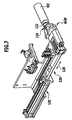
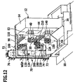
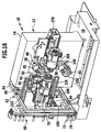
- An in Fig. 1 illustrated first embodiment of a machine tool 10 includes a machine frame 12 having a machine bed body 14 and a machine bed body 14 supporting the base 16, with which the machine frame 12 is arranged on a footprint 18.
- the machine bed body 14 comprises two pillars 20 and 22 which rise above the substructure and extend approximately parallel to each other, whose longitudinal axes 24, 26 extend approximately parallel and transversely, preferably perpendicular to the footprint 18.
- passages 28, 30 are provided between the columns 20 and 22, which are bounded by extending between the columns 20, 22 transverse struts 32, 34, 36.
- the machine bed body 14 encloses the passages 28 and 30 yoke-like and thus forms an overall stable and torsionally rigid structure.
- a designated as a whole with 40 first tool carrier is held, which projects into a working space 42 which lies in front of a front side 44 of the machine bed body 14, wherein the tool holder 40 sits on a guide base 46, which preferably passes through the passage 28 ,
- Such a machine frame 12 is for example still in detail in the German patent applications DE 10 2006 026 183 and DE 10 2006 026 184 described.
- the first tool carrier 40 is provided with a first tool spindle 50, in the tool holder 52, a tool WZ can be used.
- Such a tool WZ is rotatably driven by the tool spindle 50 about a tool spindle axis 54 and is used for machining either stationary on the machine frame 12 arranged workpieces or for example in workpiece spindles, which are not shown in the first embodiment, held workpieces.
- the machine tool 10 is provided with a tool changer 60, designated as a whole, which can be mounted on the machine frame 12, in particular the machine bed body 14.
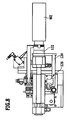
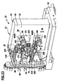
- the tool changing device 60 has, as in particular in Fig. 2 and 3 6, shown as a whole as 62, which includes a frame 64 mountable by support arms 66a-66d to an outer side 68 of the machine bed body 14, the outer side 68 preferably transverse to the front side 44 and approximately parallel to the longitudinal directions 24 , 26 and thus approximately transverse to the footprint 18 extends.
- the tool magazine 70 is in turn designed as a chain magazine and comprises a circumferential storage chain 72, on which memory receptacles 74 are provided, wherein in the memory receptacles 74 tools WZ can be used.
- the storage chain 72 is in turn guided on a chain carrier 76, which is provided with an orbit 78, on which the storage chain 72 is held circumferentially and guided so that the storage receptacles move in a storage level E1, wherein the storage level E1 transverse to the front page 44th and extends at a distance from the outside 68.
- the storage chain 72 is circumferentially drivable by a drive unit 79, so that each of the storage receptacles 74 is movable so that the tool WZ can be brought into a tool exchange position WAP, from which the tool WZ from the first control unit 80 and removable the tool holder 52 of the tool spindle 50 standing in the tool change position WWS can be used, in which case the tool WZ can be inserted into the tool holder Fig. 1 shown tool change position WWP can be brought.
- a tool gripper 90 which is designed as a multi-gripper, and a plurality, for example, two tool holding elements 92a and 92b, which are arranged for example on a gripper arm 94, which in turn is pivotally mounted about a pivot axis 96 on a generally designated 100 gripper base.
- the gripper arm 94 is held on a shaft 98, which in turn is pivotally mounted in the gripper base 100 about the pivot axis 96 and additionally in the direction 97 parallel to the pivot axis 96.
- the gripper base 100 comprises a housing 102, into which the shaft 98 is guided and in which the shaft 98 is rotatably mounted about the pivot axis 96 and parallel to this.
- the housing 102 is associated with a drive 104, which serves to pivot the shaft 98 together with the gripper arm 94 about the pivot axis 96 and to move in the same direction to the gripper arm 94 with the tool holding elements 92a and 92b for replacing the tool Tool from the tool spindle 50 of standing in the tool change position WWS tool carrier 40 to move.
- a drive 104 which serves to pivot the shaft 98 together with the gripper arm 94 about the pivot axis 96 and to move in the same direction to the gripper arm 94 with the tool holding elements 92a and 92b for replacing the tool Tool from the tool spindle 50 of standing in the tool change position WWS tool carrier 40 to move.
- the drive 104 preferably drives a slide drive device, which is not shown in the drawing and provided in the housing 102, which performs the pivotal movement of the gripper arm 94 about the pivot axis 96 and the movement of the same in the direction 97 parallel to the pivot axis 96.
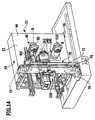
- the entire gripper base 100 is in turn guided on a longitudinal guide 110, wherein the longitudinal guide 110 is arranged on the device base 62, preferably on the frame 64, and a guide direction 112 along which the gripper base 100 is movable, so that the gripper base 100 between a tool carrier side position WSP and a magazine-side position MSP is movable.
- the gripper base 100 is in the tool carrier-side position WSP, as in Fig. 1 . 2 and Fig. 5 is shown, so that the gripper 90, for example, with the free tool holding member 92b removes the tool WZ from the tool spindle 50, rotates the gripper arm 94 by about 180 °, then positioned in the tool holder 92a tool WZ positioned in the tool change position WWP and then this tool WZ in the tool holder 52 of the tool spindle 50 changes.
- the longitudinal guide 100 passes through the storage levels E1 and thus the gripper base 100 is located in the tool carrier side position WSP on one side of the storage level E1, while the gripper base 100 is in the magazine side position MSP on the opposite side of the storage level E1.
- the gripper base 100 In the magazine-side position MSP, the gripper base 100 is positioned so that the tool gripper 90 can interact with a transfer unit 120, the gripper arm 94 not facing the tool change position WWP is turned ( Fig. 6 ), so that the transfer unit (120) is able to remove in the tool exchange position WAP a tool WZ from the standing in the corresponding tool exchange position WAP storage receptacle 74 and transfer in a tool transfer position WÜP the tool gripper 90.
- the transfer unit 120 as in Fig. 7 and 8th illustrated, preferably designed so that it has a respective tool WZ on a machine-side tool interface 122 first transfer gripper 124 which is guided on a guide 126 which forms, for example, a linear guide for the transfer gripper 124, linearly displaceable in a direction of extension 128 and thus from the position in which an acquisition of the tool WZ in the tool exchange position WAP takes place, as far as in the direction of the extension direction 128 is movable, that the tool WZ is in the tool transfer position WÜP, in which this can be taken over by the tool gripper 90.
- a guide 126 which forms, for example, a linear guide for the transfer gripper 124, linearly displaceable in a direction of extension 128 and thus from the position in which an acquisition of the tool WZ in the tool exchange position WAP takes place, as far as in the direction of the extension direction 128 is movable, that the tool WZ is in the tool transfer position WÜP, in which this can be taken
- the transfer unit 120 thus makes it possible, during the time of the method of the gripper base 100, from the magazine-side position MSP into the tool carrier-side position WSP and during the tool change in the tool spindle 50, to transfer the tool WZ to the transfer gripper 124 in the tool exchange position WAP (FIG. Fig. 3 ) into a memory receptacle 74 of the memory chain 72 and after moving the memory chain 72 from another memory receptacle 74 of the memory chain 72 another, namely, for example, the next tool to be loaded WZ, and this from the tool exchange position WAP ( Figure 3) in the tool transfer position WÜP ( Fig. 4 ) to move.
- the tool is then removed from the transfer gripper 124 by the tool gripper 90 designed as a multiple gripper with the free tool holding element 92a ( Fig. 4 ), so that a tool to be newly inserted is arranged in the tool holding member 92a, and then the tool WZ is inserted from the tool holding member 92b into the transfer gripper 124, so that the tool holding member 92b is free.
- the tool gripper 90 by moving the gripper base 100 from the magazine-side position MSP into the tool carrier-side position WSP by pivoting the gripper arm through 180 °, a tool change can be performed in the tool spindle 50, in which case first with the free tool holder element 92b (FIG. Fig.
- the tool magazine 70 is arranged outside of the working space 42 and the storage chain 72 lies in the memory plane E1, which is defined by the memory receptacles 74 and runs in such a way that they Machine bed body 14 does not cut.
- the storage level E1 runs transversely, in particular perpendicular to a plane E2, which is defined by the front side 44 of the machine bed body 14.
- the tools WZ are aligned with their tool shanks 130 transversely, preferably vertically, to the storage level E1 and parallel to one another.
- the tools WZ are also in a movement of the tool exchange position WAP in the tool transfer position WÜP also movable in the storage level E1, wherein the tool shanks 130 still extend transversely, preferably perpendicular to the storage level E1.
- the alignment of the tool shanks 130 relative to the storage level E1 remains even when transferring the tools WZ in the tool transfer position WÜP in the tool gripper 90, wherein also in the tool gripper 90, the tools WZ with their tool shanks 130 when moving the same in the tool change position WWP the alignment of the shaft 130, so that even in the tool change position WWP the tools WZ are aligned with their shafts 130, as they are aligned in exchange position WAP and the tool transfer position WÜP and are loaded in this orientation in the tool holder 52 of the tool spindle 50, with the result in that also the tool holder 52 and in particular the tool spindle axis 54 are to be aligned so that they are aligned transversely, preferably perpendicular to the storage plane E1 and thus approximately parallel to the respective tool shank 130.
- the machine-side tool interface 122 of the tools WZ held in the storage receptacles 74 of the storage chain 72 extend with their axis of symmetry 123 transversely, for example perpendicular to the axis Memory level E1 and remain in this orientation, even if the tools WZ in the region of the machine-side tool interface 122 gripped by the transfer gripper 124 and brought from the tool exchange position WAP in the tool transfer position WÜP and gripped by the tool gripper 90.
- the tools WZ are movable in a plane E3 extending parallel to a plane E2 defined by the front side 44 of the machine bed body 14, in such a way that the symmetry axis 123 is in the plane E3 or at least approximately parallel to this plane E3.
- the tools WZ from the tool transfer WÜP in the tool change position WWP can be brought, in which an exchange of tools WZ takes place in that the respective machine-side tool interface 122 aligned in its axis of symmetry 123 coaxial with the tool spindle axis 54 and extending in a direction parallel to the tool spindle axis 54 Inserting direction 132 is inserted into the tool holder 52.
- the respective machine-side tool interface 122 by pivoting the tool gripper 90 about the pivot axis 96 still transversely to the plane E3 movable and movable by moving the tool gripper 90 in the direction of the pivot axis 96 in the insertion direction 132, wherein the alignment of the axis of symmetry 123 of the tools WZ in the tool magazine 70 is still substantially parallel.
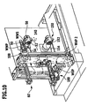
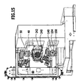
- a second tool carrier 140 is provided, which is provided with a second tool spindle 150.
- the tool changing device 60 not only the first operating device 80, but a second operating device 180, which is constructed in the same way as the first operating device, and serves, from the tool magazine 70, namely a second tool exchange position WAP Remove workpiece and insert into the tool holder 152 of the second tool spindle 150.
- the second operating device 180 comprises a tool gripper 190 which is designed as a double gripper and arranged on a gripper base 200 which is constructed and constructed in the same way as the first gripper base 100 and on a longitudinal guide 210 is guided.
- the second operating device 180 also comprises the second transfer unit 220, whose transfer gripper 224 operates in the same way as the transfer gripper 124 of the first transfer unit 120.
- a workpiece spindle 240 for receiving a workpiece which can be processed for example by the tool WZ the first tool spindle 50 or a tool WZ the second workpiece spindle 150, provided a relative movement between the workpiece spindle 240 and the tool carriers 140 or 40 is possible so far that the respective tools WZ reach the workpiece in the workpiece spindle 240.
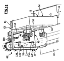
- the workpiece spindle 240 is arranged and aligned such that its workpiece spindle axis 242 is approximately parallel to the plane E2 and preferably perpendicular to the plane E1. Furthermore, the workpiece spindle 240 is arranged such that it lies between the longitudinal guides 110 and 210 of the operating devices 80 and 180, so that the respective gripper base 100 or 200 can also be moved laterally past the workpiece spindle 240, without them colliding with the workpiece spindle 240.
- the tool carriers 40 and 140 are respectively positioned in their tool change positions WWS such that the tool spindle axes 54 and 154 respectively extend at a distance from the workpiece spindle 240 on both sides.
- the tool spindle axes 54 and 154 preferably lie in tool carriers 40, 140 which are in the tool change position WWS in a common plane E4, which in turn runs parallel to the workpiece spindle axis 242 and thus parallel to the Z direction during machining of the workpiece.
- the plane E4 is preferably parallel to the plane E3 and thus preferably also approximately parallel to a front side 44 of the machine bed body 14th
- the workpiece spindle 240 can be displaced by a carriage system 250 in the direction of the workpiece spindle axis 242 and thus in the Z direction relative to the machine bed body 14, so that, for example, a relative movement in the Z direction can be achieved by moving a workpiece held in the workpiece spindle 240 the workpiece spindle 240 takes place in the Z-direction by means of the carriage system 250 and on the other hand, the tool carriers 40 and 140 in turn in the X-direction and the Y-direction relative to the machine bed body 14 are movable and also about a so-called B-axis parallel to the Y-axis, are rotatable.
- an extended embodiment which in addition to the workpiece spindle 240 has a second workpiece spindle 260, which in turn is movable relative to the machine bed body 14 in a so-called X-direction, that a carriage system supporting the workpiece spindle 260 and leading in the Z direction in X.
- a carriage system supporting the workpiece spindle 260 and leading in the Z direction in X is also performed as a carriage system.
- the second workpiece spindle 260 is movable in the Z-direction by the carriage system 270 and movable together with the carriage system 270 in the X-direction relative to the machine bed body 14 so that the second workpiece spindle 260 can be aligned coaxially with the first workpiece spindle 240 on the one hand, however
- the second tool carrier 140 can be moved to arrange this workpiece spindle 260, for example, with its workpiece spindle axis 262 coaxial or non-coaxial relative to the second tool carrier 140, wherein the second tool holder 140 may be arranged stationary, for example, in this case, that is not in X.
- Direction is displaceable relative to the machine bed body 14, but only about its B-axis B2 is rotatable and optionally in the Y direction is displaceable.
- the first tool carrier 40 is still rotatable in its B1 axis and, in turn, preferably still displaceable relative to the machine bed body at least in the X direction, in particular also in the Y direction.
- the first plane E1 or storage plane preferably runs perpendicular to the plane E2 and thus also preferably perpendicular to the workpiece spindle axes 242 and 262.
- the workpiece spindle axes 242 and 262 are preferably in a plane E5, which in particular runs parallel to the plane E3 and thus also parallel to the plane E4, and may be arranged so that it coincides with the plane E4.
- the tool holding elements 92 lie in a plane parallel to the plane E2 E6 and are movable in this.
Landscapes
- Engineering & Computer Science (AREA)
- Mechanical Engineering (AREA)
- Automatic Tool Replacement In Machine Tools (AREA)
- Constituent Portions Of Griding Lathes, Driving, Sensing And Control (AREA)
- Finish Polishing, Edge Sharpening, And Grinding By Specific Grinding Devices (AREA)
Claims (11)
- Dispositif de changement d'outil pour des machines-outils (10) présentant au moins un porte-outil (40, 140), comportant un magasin d'outil (70) avec un élément de stockage (72) présentant une pluralité de logements de stockage (74) qui peut être déplacé pour le transport des logements de stockage (74) dans au moins une position de remplacement d'outil (WAP), et avec au moins un premier appareil de commande (80, 180) avec lequel peut être réalisée une remise d'un outil (WZ) entre la position de remplacement d'outil (WAP) et une position de changement d'outil (WWP) de manière définie par un logement d'outil (52, 152) de l'au moins un porte-outil (40, 140) se trouvant dans une position de changement d'outil, caractérisé en ce que le magasin d'outil (70) est disposé à côté d'un corps de socle de machine (14) du bâti de machine (12), en ce que le dispositif de changement d'outil (60) présente une base de dispositif (62) pouvant être montée sur le bâti de machine (12) de la machine-outil (10), sur laquelle non seulement le magasin d'outil (70) mais aussi l'appareil de commande (80, 180) sont maintenus, en ce que l'appareil de commande (80, 180) présente un guidage longitudinal (110, 210) prévu sur la base de dispositif (62), le long duquel une pince d'outil (90, 190) de l'appareil de commande (80, 180) peut être déplacée, en ce que la pince d'outil (90, 190) peut être déplacée entre une position côté magasin (MSP) et une position côté porte-outil (WSP) le long du guidage longitudinal (110, 210) et en ce que la pince d'outil est pourvue d'une pince multiple (94), avec laquelle plusieurs outils (WZ) peuvent être saisis par plusieurs éléments de retenue d'outil (92).
- Dispositif de changement d'outil selon la revendication 1, caractérisé en ce que le magasin d'outil (70) est disposé près d'un côté (68) s'étendant transversalement à un axe Z du corps de socle de machine (14).
- Dispositif de changement d'outil selon la revendication 1 ou 2, caractérisé en ce que le magasin d'outil (70) et le premier appareil de commande (80, 180) sont disposés de manière à coopérer fonctionnellement sur la machine-outil (10) et en ce que le dispositif de changement d'outil (60) ne peut être monté sur un bâti (12) de machine-outil (10) comme une unité essentiellement qu'en orientant le dispositif de changement d'outil (60) par rapport à l'au moins un porte-outil (40, 140) se trouvant dans la position de changement d'outil (WWS).
- Dispositif de changement d'outil selon la revendication 1, caractérisé en ce que le magasin d'outil (70) est disposé en dehors d'un espace de travail (42) de la machine-outil (10).
- Dispositif de changement d'outil selon l'une quelconque des revendications précédentes, caractérisé en ce que le guidage (110, 210) s'étend parallèlement à un plan d'usinage (E3) du porte-outil (40, 140) défini par deux axes de déplacement (X, Z) prescrits.
- Dispositif de changement d'outil selon l'une quelconque des revendications précédentes, caractérisé en ce que l'élément de stockage (72) s'étend dans un plan de stockage (E1) et en ce que par exemple le guidage (110, 210) traverse le plan de stockage (E1).
- Dispositif de changement d'outil selon l'une quelconque des revendications précédentes, caractérisé en ce que la pince d'outil (90, 190) se trouve, dans la position côté magasin (MSP), sur un côté du plan de stockage (E1) et, dans la position côté porte-outil (WSP), de l'autre côté du plan de stockage (E1).
- Dispositif de changement d'outil selon l'une quelconque des revendications précédentes, caractérisé en ce que la pince multiple (94) est logée de manière mobile sur une base de pince (100, 200).
- Dispositif de changement d'outil selon l'une quelconque des revendications précédentes, caractérisé en ce que l'appareil de commande (80, 180) présente une unité de remise (120, 220) affectée à la position côté magasin (MSP) de la pince multiple (94), avec laquelle un outil (WZ) peut être déplacé entre la position de remplacement d'outil (WAP) et une position de remise d'outil (WÜP) pour la pince multiple (94).
- Dispositif de changement d'outil selon l'une quelconque des revendications précédentes, caractérisé en ce que le dispositif de changement d'outil (60) présente un second appareil de commande (180), avec lequel peut être réalisée une remise d'un outil (WZ) entre une deuxième position de remplacement d'outil (WAP) du magasin d'outil (70) et une position de changement d'outil (WWP).
- Machine-outil comprenant un bâti de machine, un logement de pièces (240) disposé sur le bâti de machine (12) et au moins un porte-outil (40, 140) disposé sur le bâti de machine (12), avec lequel des pièces maintenues dans le logement d'outil (240) peuvent être usinées et qui peut être positionné dans une position de changement d'outil (WWS), caractérisée en ce que la machine-outil (10) présente un dispositif de changement d'outil (60) qui est réalisé selon l'une quelconque des revendications précédentes.
Applications Claiming Priority (2)
| Application Number | Priority Date | Filing Date | Title |
|---|---|---|---|
| DE102007018710A DE102007018710A1 (de) | 2007-04-16 | 2007-04-16 | Werkzeugwechselvorrichtung |
| PCT/EP2008/002919 WO2008125310A1 (fr) | 2007-04-16 | 2008-04-12 | Dispositif de changement d'outil |
Publications (2)
| Publication Number | Publication Date |
|---|---|
| EP2139641A1 EP2139641A1 (fr) | 2010-01-06 |
| EP2139641B1 true EP2139641B1 (fr) | 2011-03-02 |
Family
ID=39591911
Family Applications (1)
| Application Number | Title | Priority Date | Filing Date |
|---|---|---|---|
| EP08735204A Not-in-force EP2139641B1 (fr) | 2007-04-16 | 2008-04-12 | Dispositif de changement d'outil |
Country Status (6)
| Country | Link |
|---|---|
| US (1) | US20100210433A1 (fr) |
| EP (1) | EP2139641B1 (fr) |
| AT (1) | ATE500025T1 (fr) |
| BR (1) | BRPI0810034A2 (fr) |
| DE (2) | DE102007018710A1 (fr) |
| WO (1) | WO2008125310A1 (fr) |
Families Citing this family (5)
| Publication number | Priority date | Publication date | Assignee | Title |
|---|---|---|---|---|
| DE102007018710A1 (de) * | 2007-04-16 | 2008-10-23 | Index-Werke Gmbh & Co. Kg Hahn & Tessky | Werkzeugwechselvorrichtung |
| DE102022111683A1 (de) | 2021-12-23 | 2023-06-29 | Index-Werke Gmbh & Co. Kg Hahn & Tessky | Mehrspindelwerkzeugmaschine |
| US12599996B2 (en) | 2021-12-23 | 2026-04-14 | Index-Werke Gmbh & Co. Kg Hahn & Tessky | Multi-spindle machine tool |
| JP2023127831A (ja) * | 2022-03-02 | 2023-09-14 | Dgshape株式会社 | 収容部材 |
| US20240286199A1 (en) * | 2023-02-28 | 2024-08-29 | Fives Giddings & Lewis, Llc | Adjacent turning and milling tool mount |
Family Cites Families (17)
| Publication number | Priority date | Publication date | Assignee | Title |
|---|---|---|---|---|
| US3587873A (en) * | 1969-05-15 | 1971-06-28 | Kearney & Trecker Corp | Tool change mechanism for a machine tool |
| JPS52103082A (en) * | 1976-02-25 | 1977-08-29 | Toyoda Mach Works Ltd | Article transfer device |
| JPS5935740B2 (ja) * | 1982-07-30 | 1984-08-30 | キタムラ機械株式会社 | 工具自動交換装置 |
| DE8435353U1 (de) * | 1984-12-03 | 1985-03-28 | Maho Werkzeugmaschinenbau Babel & Co, 8962 Pfronten | Bearbeitungszentrum für Fräs- und Bohrarbeiten |
| DE3623201A1 (de) * | 1986-07-10 | 1988-02-04 | Wotan Werke Gmbh | Werkzeugwechselvorrichtung fuer werkzeugmaschinen |
| WO1993005926A1 (fr) * | 1991-09-19 | 1993-04-01 | Mikron Sa Agno | Centre d'usinage servant a usiner une piece a l'aide d'au moins deux outils interchangeables |
| JPH10263971A (ja) * | 1997-03-25 | 1998-10-06 | Brother Ind Ltd | 工作機械の工具交換装置 |
| JPH11138374A (ja) * | 1997-09-04 | 1999-05-25 | Mori Seiki Co Ltd | 複合加工型旋盤 |
| US6416450B2 (en) * | 1999-07-28 | 2002-07-09 | Thermwood Corporation | Machine tool with improved tool changer means |
| DE10020801B4 (de) * | 2000-04-28 | 2004-07-08 | Deckel Maho Geretsried Gmbh | Werkzeughandhabungssystem für eine Werkzeugmaschine |
| JP2002036052A (ja) * | 2000-07-25 | 2002-02-05 | Sankyo Mfg Co Ltd | 自動工具交換装置 |
| DE20306087U1 (de) * | 2003-04-15 | 2003-06-12 | Hüller Hille GmbH, 71636 Ludwigsburg | Werkzeugmaschine mit Werkzeug-Magazin |
| DE102004028151A1 (de) * | 2004-06-10 | 2005-12-29 | Mikron Comp-Tec Ag | Speicheranordnung für Bearbeitungsmaschinen |
| JP4542001B2 (ja) * | 2005-09-13 | 2010-09-08 | 株式会社森精機製作所 | 工作機械 |
| DE102006026184A1 (de) | 2006-05-30 | 2007-12-06 | Index-Werke Gmbh & Co. Kg Hahn & Tessky | Drehbearbeitungszentrum |
| DE102006026183A1 (de) | 2006-05-30 | 2007-12-06 | Index-Werke Gmbh & Co. Kg Hahn & Tessky | Drehbearbeitungszentrum |
| DE102007018710A1 (de) * | 2007-04-16 | 2008-10-23 | Index-Werke Gmbh & Co. Kg Hahn & Tessky | Werkzeugwechselvorrichtung |
-
2007
- 2007-04-16 DE DE102007018710A patent/DE102007018710A1/de not_active Withdrawn
-
2008
- 2008-04-12 WO PCT/EP2008/002919 patent/WO2008125310A1/fr not_active Ceased
- 2008-04-12 AT AT08735204T patent/ATE500025T1/de active
- 2008-04-12 DE DE502008002738T patent/DE502008002738D1/de active Active
- 2008-04-12 EP EP08735204A patent/EP2139641B1/fr not_active Not-in-force
- 2008-04-12 BR BRPI0810034-9A2A patent/BRPI0810034A2/pt not_active IP Right Cessation
-
2009
- 2009-10-15 US US12/579,834 patent/US20100210433A1/en not_active Abandoned
Also Published As
| Publication number | Publication date |
|---|---|
| ATE500025T1 (de) | 2011-03-15 |
| DE102007018710A1 (de) | 2008-10-23 |
| WO2008125310A1 (fr) | 2008-10-23 |
| BRPI0810034A2 (pt) | 2014-10-14 |
| DE502008002738D1 (de) | 2011-04-14 |
| US20100210433A1 (en) | 2010-08-19 |
| EP2139641A1 (fr) | 2010-01-06 |
Similar Documents
| Publication | Publication Date | Title |
|---|---|---|
| EP1765550B1 (fr) | Machine-outil | |
| EP1118428B2 (fr) | Tour | |
| EP1718435B1 (fr) | Machine d'usinage pour usiner des pieces | |
| DE102007004633B4 (de) | System zum Wechseln der Werkzeuge in einer Maschine zur Holzbearbeitung | |
| DE10116994A1 (de) | Werkzeugmaschine | |
| EP0154349B1 (fr) | Dispositif pour changer des outils ou des objets similaires dans la broche d'une machine-outil | |
| EP2139641B1 (fr) | Dispositif de changement d'outil | |
| EP3031572A1 (fr) | Dispositif de changement d'outil destine a etre utilise dans un centre d'usinage et centre d'usinage destine a l'usinage mecanique d'une piece a usiner | |
| EP1927429A1 (fr) | Machine-outil avec magasin à outils | |
| DE19800034C2 (de) | Werkzeugmaschine für Bearbeitungswerkzeuge aus der Gruppe Schleifkörper und Fräser | |
| DE102009009969A1 (de) | Werkzeugmaschine | |
| EP1511596B1 (fr) | Tour multibroche | |
| EP1106304B1 (fr) | Machine-Outil | |
| DE102017121295A1 (de) | Mehrspindeldrehmaschine | |
| EP1281475B1 (fr) | Machine-outil avec deux broches pour pièces de travail et deux supports d'outils | |
| EP1752241B1 (fr) | Tour d'usinage | |
| DE3618959A1 (de) | Werkzeugmaschine zum spanabhebenden bearbeiten von werkstuecken | |
| DE102015121925A1 (de) | Werkzeugmaschine | |
| WO2009033929A2 (fr) | Tour | |
| EP1862256B1 (fr) | Centre de traitement rotatif | |
| DE102014113206A1 (de) | Werkzeugmaschine | |
| DE9014433U1 (de) | Werkzeugmaschine mit einem Hintergrundmagazin | |
| DE102014113204A1 (de) | Werkzeugmaschine | |
| DE4022706C2 (de) | Drehmaschine | |
| EP1270146B1 (fr) | Tour |
Legal Events
| Date | Code | Title | Description |
|---|---|---|---|
| PUAI | Public reference made under article 153(3) epc to a published international application that has entered the european phase |
Free format text: ORIGINAL CODE: 0009012 |
|
| 17P | Request for examination filed |
Effective date: 20091013 |
|
| AK | Designated contracting states |
Kind code of ref document: A1 Designated state(s): AT BE BG CH CY CZ DE DK EE ES FI FR GB GR HR HU IE IS IT LI LT LU LV MC MT NL NO PL PT RO SE SI SK TR |
|
| 17Q | First examination report despatched |
Effective date: 20100202 |
|
| DAX | Request for extension of the european patent (deleted) | ||
| GRAP | Despatch of communication of intention to grant a patent |
Free format text: ORIGINAL CODE: EPIDOSNIGR1 |
|
| GRAA | (expected) grant |
Free format text: ORIGINAL CODE: 0009210 |
|
| GRAS | Grant fee paid |
Free format text: ORIGINAL CODE: EPIDOSNIGR3 |
|
| AK | Designated contracting states |
Kind code of ref document: B1 Designated state(s): AT BE BG CH CY CZ DE DK EE ES FI FR GB GR HR HU IE IS IT LI LT LU LV MC MT NL NO PL PT RO SE SI SK TR |
|
| REG | Reference to a national code |
Ref country code: GB Ref legal event code: FG4D Free format text: NOT ENGLISH |
|
| REG | Reference to a national code |
Ref country code: CH Ref legal event code: EP |
|
| REG | Reference to a national code |
Ref country code: IE Ref legal event code: FG4D Free format text: LANGUAGE OF EP DOCUMENT: GERMAN |
|
| REG | Reference to a national code |
Ref country code: CH Ref legal event code: NV Representative=s name: KIRKER & CIE S.A. |
|
| REF | Corresponds to: |
Ref document number: 502008002738 Country of ref document: DE Date of ref document: 20110414 Kind code of ref document: P |
|
| REG | Reference to a national code |
Ref country code: DE Ref legal event code: R096 Ref document number: 502008002738 Country of ref document: DE Effective date: 20110414 |
|
| REG | Reference to a national code |
Ref country code: NL Ref legal event code: VDEP Effective date: 20110302 |
|
| PG25 | Lapsed in a contracting state [announced via postgrant information from national office to epo] |
Ref country code: SE Free format text: LAPSE BECAUSE OF FAILURE TO SUBMIT A TRANSLATION OF THE DESCRIPTION OR TO PAY THE FEE WITHIN THE PRESCRIBED TIME-LIMIT Effective date: 20110302 Ref country code: NO Free format text: LAPSE BECAUSE OF FAILURE TO SUBMIT A TRANSLATION OF THE DESCRIPTION OR TO PAY THE FEE WITHIN THE PRESCRIBED TIME-LIMIT Effective date: 20110602 Ref country code: HR Free format text: LAPSE BECAUSE OF FAILURE TO SUBMIT A TRANSLATION OF THE DESCRIPTION OR TO PAY THE FEE WITHIN THE PRESCRIBED TIME-LIMIT Effective date: 20110302 Ref country code: LV Free format text: LAPSE BECAUSE OF FAILURE TO SUBMIT A TRANSLATION OF THE DESCRIPTION OR TO PAY THE FEE WITHIN THE PRESCRIBED TIME-LIMIT Effective date: 20110302 Ref country code: LT Free format text: LAPSE BECAUSE OF FAILURE TO SUBMIT A TRANSLATION OF THE DESCRIPTION OR TO PAY THE FEE WITHIN THE PRESCRIBED TIME-LIMIT Effective date: 20110302 Ref country code: GR Free format text: LAPSE BECAUSE OF FAILURE TO SUBMIT A TRANSLATION OF THE DESCRIPTION OR TO PAY THE FEE WITHIN THE PRESCRIBED TIME-LIMIT Effective date: 20110603 Ref country code: ES Free format text: LAPSE BECAUSE OF FAILURE TO SUBMIT A TRANSLATION OF THE DESCRIPTION OR TO PAY THE FEE WITHIN THE PRESCRIBED TIME-LIMIT Effective date: 20110613 |
|
| LTIE | Lt: invalidation of european patent or patent extension |
Effective date: 20110302 |
|
| PG25 | Lapsed in a contracting state [announced via postgrant information from national office to epo] |
Ref country code: SI Free format text: LAPSE BECAUSE OF FAILURE TO SUBMIT A TRANSLATION OF THE DESCRIPTION OR TO PAY THE FEE WITHIN THE PRESCRIBED TIME-LIMIT Effective date: 20110302 Ref country code: CY Free format text: LAPSE BECAUSE OF FAILURE TO SUBMIT A TRANSLATION OF THE DESCRIPTION OR TO PAY THE FEE WITHIN THE PRESCRIBED TIME-LIMIT Effective date: 20110302 Ref country code: FI Free format text: LAPSE BECAUSE OF FAILURE TO SUBMIT A TRANSLATION OF THE DESCRIPTION OR TO PAY THE FEE WITHIN THE PRESCRIBED TIME-LIMIT Effective date: 20110302 Ref country code: NL Free format text: LAPSE BECAUSE OF FAILURE TO SUBMIT A TRANSLATION OF THE DESCRIPTION OR TO PAY THE FEE WITHIN THE PRESCRIBED TIME-LIMIT Effective date: 20110302 Ref country code: BG Free format text: LAPSE BECAUSE OF FAILURE TO SUBMIT A TRANSLATION OF THE DESCRIPTION OR TO PAY THE FEE WITHIN THE PRESCRIBED TIME-LIMIT Effective date: 20110602 |
|
| REG | Reference to a national code |
Ref country code: IE Ref legal event code: FD4D |
|
| BERE | Be: lapsed |
Owner name: INDEX-WERKE G.M.B.H. & CO. KG HAHN & TESSKY Effective date: 20110430 |
|
| PG25 | Lapsed in a contracting state [announced via postgrant information from national office to epo] |
Ref country code: IE Free format text: LAPSE BECAUSE OF FAILURE TO SUBMIT A TRANSLATION OF THE DESCRIPTION OR TO PAY THE FEE WITHIN THE PRESCRIBED TIME-LIMIT Effective date: 20110302 Ref country code: EE Free format text: LAPSE BECAUSE OF FAILURE TO SUBMIT A TRANSLATION OF THE DESCRIPTION OR TO PAY THE FEE WITHIN THE PRESCRIBED TIME-LIMIT Effective date: 20110302 Ref country code: PT Free format text: LAPSE BECAUSE OF FAILURE TO SUBMIT A TRANSLATION OF THE DESCRIPTION OR TO PAY THE FEE WITHIN THE PRESCRIBED TIME-LIMIT Effective date: 20110704 |
|
| PG25 | Lapsed in a contracting state [announced via postgrant information from national office to epo] |
Ref country code: RO Free format text: LAPSE BECAUSE OF FAILURE TO SUBMIT A TRANSLATION OF THE DESCRIPTION OR TO PAY THE FEE WITHIN THE PRESCRIBED TIME-LIMIT Effective date: 20110302 Ref country code: MC Free format text: LAPSE BECAUSE OF NON-PAYMENT OF DUE FEES Effective date: 20110430 Ref country code: CZ Free format text: LAPSE BECAUSE OF FAILURE TO SUBMIT A TRANSLATION OF THE DESCRIPTION OR TO PAY THE FEE WITHIN THE PRESCRIBED TIME-LIMIT Effective date: 20110302 Ref country code: IS Free format text: LAPSE BECAUSE OF FAILURE TO SUBMIT A TRANSLATION OF THE DESCRIPTION OR TO PAY THE FEE WITHIN THE PRESCRIBED TIME-LIMIT Effective date: 20110702 Ref country code: SK Free format text: LAPSE BECAUSE OF FAILURE TO SUBMIT A TRANSLATION OF THE DESCRIPTION OR TO PAY THE FEE WITHIN THE PRESCRIBED TIME-LIMIT Effective date: 20110302 |
|
| PG25 | Lapsed in a contracting state [announced via postgrant information from national office to epo] |
Ref country code: MT Free format text: LAPSE BECAUSE OF FAILURE TO SUBMIT A TRANSLATION OF THE DESCRIPTION OR TO PAY THE FEE WITHIN THE PRESCRIBED TIME-LIMIT Effective date: 20110302 |
|
| PLBE | No opposition filed within time limit |
Free format text: ORIGINAL CODE: 0009261 |
|
| STAA | Information on the status of an ep patent application or granted ep patent |
Free format text: STATUS: NO OPPOSITION FILED WITHIN TIME LIMIT |
|
| PG25 | Lapsed in a contracting state [announced via postgrant information from national office to epo] |
Ref country code: BE Free format text: LAPSE BECAUSE OF NON-PAYMENT OF DUE FEES Effective date: 20110430 |
|
| 26N | No opposition filed |
Effective date: 20111205 |
|
| PG25 | Lapsed in a contracting state [announced via postgrant information from national office to epo] |
Ref country code: PL Free format text: LAPSE BECAUSE OF FAILURE TO SUBMIT A TRANSLATION OF THE DESCRIPTION OR TO PAY THE FEE WITHIN THE PRESCRIBED TIME-LIMIT Effective date: 20110302 Ref country code: DK Free format text: LAPSE BECAUSE OF FAILURE TO SUBMIT A TRANSLATION OF THE DESCRIPTION OR TO PAY THE FEE WITHIN THE PRESCRIBED TIME-LIMIT Effective date: 20110302 |
|
| REG | Reference to a national code |
Ref country code: DE Ref legal event code: R097 Ref document number: 502008002738 Country of ref document: DE Effective date: 20111205 |
|
| PG25 | Lapsed in a contracting state [announced via postgrant information from national office to epo] |
Ref country code: IT Free format text: LAPSE BECAUSE OF FAILURE TO SUBMIT A TRANSLATION OF THE DESCRIPTION OR TO PAY THE FEE WITHIN THE PRESCRIBED TIME-LIMIT Effective date: 20110302 |
|
| PGFP | Annual fee paid to national office [announced via postgrant information from national office to epo] |
Ref country code: GB Payment date: 20120411 Year of fee payment: 5 |
|
| PG25 | Lapsed in a contracting state [announced via postgrant information from national office to epo] |
Ref country code: LU Free format text: LAPSE BECAUSE OF NON-PAYMENT OF DUE FEES Effective date: 20110412 |
|
| PG25 | Lapsed in a contracting state [announced via postgrant information from national office to epo] |
Ref country code: TR Free format text: LAPSE BECAUSE OF FAILURE TO SUBMIT A TRANSLATION OF THE DESCRIPTION OR TO PAY THE FEE WITHIN THE PRESCRIBED TIME-LIMIT Effective date: 20110302 |
|
| PG25 | Lapsed in a contracting state [announced via postgrant information from national office to epo] |
Ref country code: HU Free format text: LAPSE BECAUSE OF FAILURE TO SUBMIT A TRANSLATION OF THE DESCRIPTION OR TO PAY THE FEE WITHIN THE PRESCRIBED TIME-LIMIT Effective date: 20110302 |
|
| GBPC | Gb: european patent ceased through non-payment of renewal fee |
Effective date: 20130412 |
|
| PG25 | Lapsed in a contracting state [announced via postgrant information from national office to epo] |
Ref country code: GB Free format text: LAPSE BECAUSE OF NON-PAYMENT OF DUE FEES Effective date: 20130412 |
|
| REG | Reference to a national code |
Ref country code: AT Ref legal event code: MM01 Ref document number: 500025 Country of ref document: AT Kind code of ref document: T Effective date: 20130412 |
|
| PG25 | Lapsed in a contracting state [announced via postgrant information from national office to epo] |
Ref country code: AT Free format text: LAPSE BECAUSE OF NON-PAYMENT OF DUE FEES Effective date: 20130412 |
|
| REG | Reference to a national code |
Ref country code: FR Ref legal event code: PLFP Year of fee payment: 8 |
|
| REG | Reference to a national code |
Ref country code: DE Ref legal event code: R082 Ref document number: 502008002738 Country of ref document: DE Representative=s name: HOEGER, STELLRECHT & PARTNER PATENTANWAELTE MB, DE |
|
| PGFP | Annual fee paid to national office [announced via postgrant information from national office to epo] |
Ref country code: CH Payment date: 20150414 Year of fee payment: 8 |
|
| PGFP | Annual fee paid to national office [announced via postgrant information from national office to epo] |
Ref country code: FR Payment date: 20150408 Year of fee payment: 8 |
|
| REG | Reference to a national code |
Ref country code: CH Ref legal event code: PL |
|
| REG | Reference to a national code |
Ref country code: FR Ref legal event code: ST Effective date: 20161230 |
|
| PG25 | Lapsed in a contracting state [announced via postgrant information from national office to epo] |
Ref country code: CH Free format text: LAPSE BECAUSE OF NON-PAYMENT OF DUE FEES Effective date: 20160430 Ref country code: FR Free format text: LAPSE BECAUSE OF NON-PAYMENT OF DUE FEES Effective date: 20160502 Ref country code: LI Free format text: LAPSE BECAUSE OF NON-PAYMENT OF DUE FEES Effective date: 20160430 |
|
| PGFP | Annual fee paid to national office [announced via postgrant information from national office to epo] |
Ref country code: DE Payment date: 20170526 Year of fee payment: 10 |
|
| REG | Reference to a national code |
Ref country code: DE Ref legal event code: R119 Ref document number: 502008002738 Country of ref document: DE |
|
| PG25 | Lapsed in a contracting state [announced via postgrant information from national office to epo] |
Ref country code: DE Free format text: LAPSE BECAUSE OF NON-PAYMENT OF DUE FEES Effective date: 20181101 |