EP2139606B1 - Flüssigproduktverteiler - Google Patents
Flüssigproduktverteiler Download PDFInfo
- Publication number
- EP2139606B1 EP2139606B1 EP08788070.4A EP08788070A EP2139606B1 EP 2139606 B1 EP2139606 B1 EP 2139606B1 EP 08788070 A EP08788070 A EP 08788070A EP 2139606 B1 EP2139606 B1 EP 2139606B1
- Authority
- EP
- European Patent Office
- Prior art keywords
- dispenser
- chamber
- reservoir
- escape path
- lip
- Prior art date
- Legal status (The legal status is an assumption and is not a legal conclusion. Google has not performed a legal analysis and makes no representation as to the accuracy of the status listed.)
- Active
Links
Images
Classifications
-
- B—PERFORMING OPERATIONS; TRANSPORTING
- B05—SPRAYING OR ATOMISING IN GENERAL; APPLYING FLUENT MATERIALS TO SURFACES, IN GENERAL
- B05B—SPRAYING APPARATUS; ATOMISING APPARATUS; NOZZLES
- B05B11/00—Single-unit hand-held apparatus in which flow of contents is produced by the muscular force of the operator at the moment of use
- B05B11/01—Single-unit hand-held apparatus in which flow of contents is produced by the muscular force of the operator at the moment of use characterised by the means producing the flow
- B05B11/10—Pump arrangements for transferring the contents from the container to a pump chamber by a sucking effect and forcing the contents out through the dispensing nozzle
- B05B11/1001—Piston pumps
- B05B11/1016—Piston pumps the outlet valve having a valve seat located downstream a movable valve element controlled by a pressure actuated controlling element
- B05B11/1018—Piston pumps the outlet valve having a valve seat located downstream a movable valve element controlled by a pressure actuated controlling element and the controlling element cooperating with means for opening or closing the inlet valve
-
- B—PERFORMING OPERATIONS; TRANSPORTING
- B05—SPRAYING OR ATOMISING IN GENERAL; APPLYING FLUENT MATERIALS TO SURFACES, IN GENERAL
- B05B—SPRAYING APPARATUS; ATOMISING APPARATUS; NOZZLES
- B05B11/00—Single-unit hand-held apparatus in which flow of contents is produced by the muscular force of the operator at the moment of use
- B05B11/01—Single-unit hand-held apparatus in which flow of contents is produced by the muscular force of the operator at the moment of use characterised by the means producing the flow
- B05B11/10—Pump arrangements for transferring the contents from the container to a pump chamber by a sucking effect and forcing the contents out through the dispensing nozzle
- B05B11/1042—Components or details
- B05B11/1061—Pump priming means
- B05B11/1063—Air exhausted from the pump chamber being discharged into the container during priming
-
- B—PERFORMING OPERATIONS; TRANSPORTING
- B05—SPRAYING OR ATOMISING IN GENERAL; APPLYING FLUENT MATERIALS TO SURFACES, IN GENERAL
- B05B—SPRAYING APPARATUS; ATOMISING APPARATUS; NOZZLES
- B05B11/00—Single-unit hand-held apparatus in which flow of contents is produced by the muscular force of the operator at the moment of use
- B05B11/01—Single-unit hand-held apparatus in which flow of contents is produced by the muscular force of the operator at the moment of use characterised by the means producing the flow
- B05B11/10—Pump arrangements for transferring the contents from the container to a pump chamber by a sucking effect and forcing the contents out through the dispensing nozzle
- B05B11/1042—Components or details
- B05B11/1066—Pump inlet valves
- B05B11/107—Gate valves; Sliding valves
-
- B—PERFORMING OPERATIONS; TRANSPORTING
- B05—SPRAYING OR ATOMISING IN GENERAL; APPLYING FLUENT MATERIALS TO SURFACES, IN GENERAL
- B05B—SPRAYING APPARATUS; ATOMISING APPARATUS; NOZZLES
- B05B11/00—Single-unit hand-held apparatus in which flow of contents is produced by the muscular force of the operator at the moment of use
- B05B11/01—Single-unit hand-held apparatus in which flow of contents is produced by the muscular force of the operator at the moment of use characterised by the means producing the flow
- B05B11/10—Pump arrangements for transferring the contents from the container to a pump chamber by a sucking effect and forcing the contents out through the dispensing nozzle
- B05B11/1042—Components or details
- B05B11/1073—Springs
- B05B11/1074—Springs located outside pump chambers
-
- B—PERFORMING OPERATIONS; TRANSPORTING
- B05—SPRAYING OR ATOMISING IN GENERAL; APPLYING FLUENT MATERIALS TO SURFACES, IN GENERAL
- B05B—SPRAYING APPARATUS; ATOMISING APPARATUS; NOZZLES
- B05B11/00—Single-unit hand-held apparatus in which flow of contents is produced by the muscular force of the operator at the moment of use
- B05B11/01—Single-unit hand-held apparatus in which flow of contents is produced by the muscular force of the operator at the moment of use characterised by the means producing the flow
- B05B11/10—Pump arrangements for transferring the contents from the container to a pump chamber by a sucking effect and forcing the contents out through the dispensing nozzle
- B05B11/1001—Piston pumps
- B05B11/1021—Piston pumps having an outlet valve which is a gate valve
- B05B11/1022—Piston pumps having an outlet valve which is a gate valve actuated by pressure
-
- B—PERFORMING OPERATIONS; TRANSPORTING
- B05—SPRAYING OR ATOMISING IN GENERAL; APPLYING FLUENT MATERIALS TO SURFACES, IN GENERAL
- B05B—SPRAYING APPARATUS; ATOMISING APPARATUS; NOZZLES
- B05B11/00—Single-unit hand-held apparatus in which flow of contents is produced by the muscular force of the operator at the moment of use
- B05B11/01—Single-unit hand-held apparatus in which flow of contents is produced by the muscular force of the operator at the moment of use characterised by the means producing the flow
- B05B11/10—Pump arrangements for transferring the contents from the container to a pump chamber by a sucking effect and forcing the contents out through the dispensing nozzle
- B05B11/1042—Components or details
- B05B11/1043—Sealing or attachment arrangements between pump and container
- B05B11/1046—Sealing or attachment arrangements between pump and container the pump chamber being arranged substantially coaxially to the neck of the container
- B05B11/1047—Sealing or attachment arrangements between pump and container the pump chamber being arranged substantially coaxially to the neck of the container the pump being preassembled as an independent unit before being mounted on the container
Definitions
- the present invention relates to a fluid dispenser comprising a reservoir provided with an opening and a dispensing member, such as a pump or a valve, mounted in the opening of the reservoir.
- a dispensing member such as a pump or a valve
- WO 2005/070560 describes a fluid dispenser whose dispensing member, which is a pump, comprises a body provided with fixing means on a tank neck, a pusher forming the dispensing orifice and on which the user can press for actuate the pump and a differential piston housed inside the pusher and sliding in a barrel formed by the body.
- a pre-compression and return spring is supported on the body and pushes the differential piston towards the pusher away from the body.
- the pump chamber formed by this dispenser member extends on either side of the differential piston: by pressing on the pusher with the aid of one or more fingers, the differential piston will move against the spring both in relation to the body and the pusher, hence its differential characteristic.
- the displacement of the differential piston relative to the pusher makes it possible to disengage a dispensing orifice through which the pressurized fluid product inside the chamber can escape and be advantageously distributed in pulverized form.
- the distributor described in the document WO 2005/070560 has reduced dimensions with a tank of the order of a few milliliters.
- the distributor is more like a sample.
- an overpressure is created inside the tank. This is because the pump body slides sealingly into the tank opening over a certain height.
- the body thus fulfills an undesired piston function: moreover, this phenomenon of overpressure is commonly referred to as "piston".
- a first object of the present invention is to mitigate or eliminate this pressure inside the tank during assembly of the dispenser.
- another object of the present invention is to allow easy and fast priming of the pump chamber.
- the present invention must allow both an elimination of the pressure in the reservoir and a priming of the pump during a single simple operation, which can be easily implemented during the distributor assembly.
- the document US-A-4,369,900 describes a pump whose pump chamber communicates with the reservoir through the inlet valve and with the outside through the outlet valve, and this in a completely depressed configuration to prime the pump.
- the present invention seeks to avoid a leakage path through the outlet valve.
- the present invention provides a fluid dispenser comprising a fluid reservoir provided with an opening, and a dispensing member, such as a pump or a valve, mounted on the reservoir opening, member forming a fluid product chamber provided with an inlet valve, an outlet valve and a displaceably movable lip in a cylindrical barrel between a position resting position and a depressed position for varying the volume of the chamber, and discharging the fluid product from the chamber through the outlet valve to a dispensing orifice, characterized in that the inlet valve defines, close to the depressed position, a first escape route which makes the tank communicate with the chamber, the communicating chamber, proximity of the depressed position, with the outside through a second leakage path that does not pass through the outlet valve and the dispensing orifice, so that the tank and the chamber communicate with the outside, close to the depressed position, through the first and second vanishing paths open with the closed outlet valve.
- the overpressure in the reservoir can be decreased or eliminated by communicating with the chamber, and the compressed air within
- the first escape path is open before the second escape path, so that the chamber communicates with the reservoir before it communicates with the outside.
- the pressure in the reservoir is equalized with the pressure prevailing in the chamber
- the common pressure in the reservoir and the chamber is equalized with the outside.
- the establishment of the first and second escape paths is effected by bringing the pusher to its depressed position. This can be done when mounting the dispenser member on the opening of the tank with a press pressing the pusher. The press begins by pushing the pusher fully into the depressed position before mounting the dispensing member in the opening of the tank.
- the two escape routes are established before any overpressure can be generated inside the tank.
- the dispensing member is brought into the final mounting position in the opening of the reservoir.
- the press then releases its pressure on the pusher returning to its rest position.
- the second escape route is closed before the first escape route.
- the inlet valve performs its normal function, creating a vacuum inside the chamber that will allow to draw fluid from the tank.
- the dispensing member is thus initiated as soon as it is mounted on the reservoir. In addition, any overpressure inside the tank is prevented.
- the lip breaks its tight sliding with the cylindrical barrel near the depressed position to establish the second escape path.
- the barrel forms at least one discontinuity on which the lip passes, thus creating the second escape path.
- the function of the discontinuity (s) is to take off at least locally the lip of the barrel to create a leakage that will serve as a leakage path for pressurized air.
- the inlet valve comprises two elements engaged to slide one inside the other, except in the rest position in which the valve is open and close to the depressed position to establish the first escape route.
- one of the elements forms at least one profile over which the other element passes, thus creating the first escape route.
- the function of the profile (s) is to create a local leakage leakage path for the pressurized air and possibly for the fluid under pressure.
- the dispensing member comprises a body intended to be mounted on the opening of the reservoir, the body forming the cylindrical barrel, an axially displaceable pusher back and forth on the body between the rest and depressed positions, a differential piston comprising a first lip slidably engaged in the barrel of the body and second lip slidably engaged in the pusher.
- the body forms an inlet pipe and the differential piston forms a rod which is slidably engaged in the pipe in such a way as to define together the inlet valve, the rod forms at least one profile at the level of which the pipe is not not in sealed contact, thus establishing the first escape route.
- the dispenser member comprises a spring which urges the differential piston toward the pusher away from the body.
- the dispensing member comprises a self-sealing sleeve which comes into sealing contact with the opening of the reservoir during assembly of the dispensing member on the reservoir.
- the present invention solves both the problem of overpressure in the tank and the problem of the priming of the dispensing member, without creating a risk of fluid leakage.
- the present invention is preferably applied to pumps, but can also be applied to valves. Similarly, it applies preferably to small capacity dispensers such as samples, but can also be applied to any other dispenser of higher capacity.
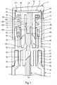
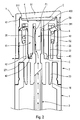
- FIGS. 1 and 2 are views in partial vertical cross section through a fluid dispenser according to the invention, respectively in the rest position and in the depressed position.
- the distributor comprises several constituent elements, namely a reservoir 1 and a dispensing member, which is in the embodiment of a pump, but it could also have been a valve.
- This pump comprises a body 2, a dip tube 3, a differential piston 4, a pusher 5 and a return and pre-compression spring 6.
- the dip tube 3 is here attached to the body 2, but it is also possible to make the dip tube in one piece with the body 2.
- the spring 6 is an independent piece, but it is possible alternatively to make it integrally with the body 2 or the differential piston 4. Therefore, the pump of the invention comprises three to five constituent elements.
- the reservoir 1 is intended to contain fluid product to be dispensed. It can be made of glass, metal or plastic. Its capacity may be of the order of two to three millimeters in the case of samples or may be much higher in the case of conventional tanks.
- the tank can have all the appropriate forms. It comprises a bottom (not shown), a side wall (partially shown), and an opening 10 defined here by a neck 11.
- This neck 11 comprises a peripheral annular groove 12 at its outer wall.
- the neck 11 also comprises an inner wall 14 which will serve to seal with the pump, as will be seen below.
- the neck 11 also defines an upper annular edge 13. Below the neck 11, the reservoir forms an outer shoulder 15 which is directed upwards. This is only a particular embodiment for the tank. In a very general way, it is sufficient that it defines a useful storage volume for the fluid product and an opening through which the fluid can be extracted from the reservoir.
- the pump used to illustrate the present invention is of the "pusher pump” type, which has the particularity that the pusher forms part of the pump chamber generally designated by C. In most cases, the pusher also defines a sliding shaft for the piston.
- the pump body 2 can be made by injection molding of suitable plastic material.
- the body is a piece that presents advantageously a symmetry of revolution around the visible X axis on the figure 1 .
- the body comprises in a very general manner two series of three concentric rings which extend on either side of a radial plate 25 which is traversed at its center by an inlet channel 20.
- the series of three concentric rings which extends downwards from the plate 25 comprises an external fixing ring 21 provided on its inner wall with a fastening cord 22 adapted to snap into the groove 12 of the neck 11.
- the ring 21 is the outermost ring.
- the body 2 comprises a self-sealing cylindrical sleeve 24 which comes into sealing contact with the inner wall 14 of the neck 11.
- the body forms a connecting sleeve 23 inside which is engaged the upper end of the dip tube 3 which extends into the tank 1 to near its bottom.
- the connecting sleeve 23 extends axially forming the inlet conduit 20.
- the ring 21, the sleeve 24 and the sleeve 23 all extend downwards from the annular radial plate 25.
- the self-sealing sleeve 24 will slide sealingly against the inner wall 14 of the neck 11 on a relatively large axial stroke.
- the cord 22 engages snap-fit inside the groove 12. This corresponds to the final mounting position of the body 2, and thus of the pump, on the reservoir.
- the series of three crowns that extend upward from the plate 25 includes an outermost guide sleeve 26 which is located the outermost.
- the guide sleeve 26 defines a shoulder 261 which will act as a stop, as will be seen below.
- the sleeve 26 serves as a bearing surface for the spring 6 which is housed between the sleeve 26 and the barrel 27.
- the body forms a sliding shaft 27 which has an inner wall essentially cylindrical.
- the inner wall of the barrel forms at least one boss or rib which defines a discontinuity 271 in the cylindricity of the barrel. Its function will be given below.
- the body further defines an inlet pipe 28 which internally defines a portion of the inlet conduit 20.
- the free upper end of the pipe 28 forms a sliding sealing bead 281, as will be seen hereinafter.
- the inlet duct 20 thus directly communicate the tubing 28 with the plunger tube 3. It should be noted that there is no system or vent passage between the body and the reservoir.
- the differential piston 4 comprises a hollow axial tube 41 whose free end defines a main piston lip 42 adapted to slide sealingly inside the barrel 27 of the body 2.
- the lip 42 is elastically deformable.
- the differential piston 4 comprises a rod 43 which performs a function of moving member of the inlet valve.
- This rod 43 advantageously defines three sections, namely a lower section 431 of reduced diameter or groove, an intermediate section 432 of maximum diameter and an upper section 433 defined with at least one protruding or hollow profile 434.
- the profile is in the form of one or more grooves which advantageously extend axially.
- the rod 43 is engaged inside the tubing 28 so that the sealing bead 281 is positioned at the reduced diameter lower section 431 when the pump is at rest, as shown in FIG. figure 1 . There is then no sealed contact between the bead 281 and the rod 43.
- the tubing 28, or more precisely its sealing bead 281 cooperates with the rod 43 to form together the inlet valve pump. Therefore, as we have just seen, the inlet valve is open in the rest position, since there is no contact between the cord 281, which serves as an inlet valve seat, and the rod 43, which serves as movable member of the inlet valve.
- the differential piston 4 forms a connecting channel 44 which passes through the tube 41.
- the differential piston 4 forms an annular flange 45 which extends radially outwards.
- this flange 45 forms a differential piston lip 46 and an annular flange 47 which serves as a movable outlet valve member, as will be seen hereinafter.
- the spring 6 bears under the annular flange 45.
- the pusher 5 comprises an upper support plate 51 on which the user can press with the aid of one or more fingers. On its outer periphery, this plate extends downwardly forming a skirt 52, here of substantially cylindrical shape.
- the skirt 52 defines near its upper end where it is connected to the plate 51 an internal distribution wall 53 at which is formed a dispensing orifice 50.
- the wall 53 also forms channels and a swirl chamber 54 centered on the orifice 50.
- the skirt 52 forms a sliding cylinder 55 which has a diameter slightly greater than that of the distribution wall 53.
- the skirt 52 forms an internal stop reinforcement 56 which is housed below the shoulder 261 of the guide sleeve 26.
- the skirt 52 also performs a guiding function by being engaged around the upper part of the sleeve 26.
- the stop reinforcement 56 prevents the withdrawal of the pusher 5 from the body 2 and defines the rest position.
- the plate 51 includes an inner bottom wall that will form a portion of the pump chamber. On the other hand, the plate 51 forms at its outer periphery an outlet valve seat 511, which has a generally frustoconical configuration.
- the differential piston 4 is engaged inside the pusher 5 so that its lip 46 comes into sealing contact with the sliding cylinder 55.
- the collar 47 comes into contact sealed with the seat 511 in the rest position, as shown on the figure 1 .
- the spring 6 urges the differential piston 4 against the plate 51 away from the body 2.
- the tube 41 is engaged inside the barrel 27 and the rod 43 is engaged inside the
- the pump chamber C defines a lower part formed between the barrel 27 and the tubing 28 and an upper part formed between the flange 45 and the plate 51. These two parts communicate with each other through the connecting channel 44. extending through the piston 4.
- the spring 6 which bears on the inner shoulder of the bushing 26 pushes the differential piston 4 away from the body 2. This has the effect of pressing the flange 47 of the piston 4 against the seat 511 of the plate 51.
- the pusher 5 is thus also biased away from the body 2 and the rest position is defined when the abutment reinforcement 56 abuts against the shoulder 261 of the sleeve 26.
- the pump chamber C is then isolated from the outside by the sealing contact between the flange 47 on the seat 511.
- the main piston lip 42 is at its highest position inside the barrel 27.
- the inlet valve it is open, since the cord 281 does not come into sealed contact with the rod 43.
- the pump chamber C then only communicates with the reservoir through the inlet duct 20 and the plunger tube 3.
- the differential piston 4 When axially pressing the push-button 5 from the rest position of the figure 1 , the differential piston 4 is driven axially downwards so that the intermediate section 432 of the rod 43 engages sealingly in the annular bead 281 of the pipe 28.
- the inlet valve is then closed and the chamber C no longer communicates with the tank.
- the pressure rises inside the chamber C, and because of the surface differential between the lower part and the upper part of the chamber, the differential piston 4 moves away from the plate 51, thus opening the valve of outlet formed by the flange 47 and the seat 511.
- the chamber C then communicates with the outside and the pressurized fluid can be dispensed through the orifice 50.
- the outlet valve For the outlet valve to open, it is necessary that the pressure inside the chamber is greater than the force exerted by the spring 6.
- the present invention is particularly interesting, not in the normal operating cycle of the dispenser, but during the mounting phase of the pump on the tank and during the priming phase of the pump. Indeed, when the pump is mounted on the tank, the self-sealing sleeve 23 slides sealingly over a certain stroke against the inner wall 14 of the neck 11. This would normally have the effect of considerably increasing the pressure at the top of the tank. inside the tank, especially when it is of a low capacity. Thanks to the escape routes F1 and F2, the air pressurized inside the tank can escape to the outside by following the arrow path of the figure 2 . In addition, this venting of the tank and the chamber allows easy and automatic priming of the pump.
- the inlet valve will close and the depression that forms inside the chamber will allow to suck fluid in the pump chamber, thus priming the pump.
- This simultaneous operation of venting the tank and priming the chamber can be performed when mounting the pump on the tank using a press that presses the pusher. The force exerted by the press will firstly snap the ring 21 on the neck 11 and secondly put the pump in the depressed position.
- Another interesting feature of the invention lies in the fact that the leak F1 is established before the leak F2, so that the chamber C first communicates with the tank and then only with the outside.
- the pressure prevailing inside the tank will first be balanced with the chamber and the residual pressure is balanced with the outside at atmospheric pressure.
- This phase shift or sequencing of the opening of the escape paths F1 and F2 also makes it possible to avoid any risk of leakage of fluid during normal operation of the dispenser. Indeed, since the escape path F1 opens before the escape path F2, the fluid remaining in the chamber C near the depressed position, when the outlet valve is closed, will be forced to flow to the tank through the F1 escape path, and not through the leakage path F2 which is still closed.
- the pressure in the chamber is no longer sufficient to keep the outlet valve open, but still higher than the pressure in the tank or the atmospheric pressure.
- the opening phase shift can be very simply achieved by providing that the seal between the bead 281 and the rod 43 is broken before the sealing contact between the lip 42 and the barrel is.
- the grooves 434 of the rod can be replaced by any configuration suitable for breaking the seal between the tubing 28 and the rod 43.
- the ribs or bosses 271 formed at the drum can be replaced by any configuration to break the seal with the lip 42.
- the second escape path F2 is separate from the outlet valve, so that the air is forced out of the chamber through the leakage path F2 while the outlet valve is and remains closed.
- venting system of the present invention thus makes it possible not only to avoid any overpressure inside the tank and to prime the pump, but also to avoid any risk of leakage during normal operation of the pump, and this advantageously through the implementation of two separate escape paths whose openings are not simultaneous.
Landscapes
- Containers And Packaging Bodies Having A Special Means To Remove Contents (AREA)
- Closures For Containers (AREA)
- Devices For Dispensing Beverages (AREA)
- Reciprocating Pumps (AREA)
Claims (10)
- Verteiler für ein flüssiges Produkt, der Folgendes umfasst:- einen Tank für das flüssige Produkt (1) versehen mit einer Öffnung (10) und- ein Verteilerorgan (2, 3, 4, 5, 6) wie eine Pumpe oder ein Ventil, montiert auf einer Öffnung (10) des Tanks, wobei dieses Organ eine Kammer mit dem flüssigen Produkt (C) bildet, die über eine Eingangsklappe (28, 43) verfügt, eine Ausgangsklappe (47, 511) und eine Lippe (42), die mit einer dichten Führung in einem zylindrischen Schaft (27) zwischen einer Ruheposition und einer eingedrückten Stellung verschiebbar ist, um das Volumen der Kammer (C) zu verändern und das flüssige Produkt der Kammer durch die Ausgangsklappe in Richtung einer Verteileröffnung (50) zurückzustauen,
dadurch gekennzeichnet, dass die Eingangsklappe in der Nähe der eingedrückten Position einen ersten Auslaufweg (F1) aufweist, der den Tank (1) mit der Kammer (C) verbindet, wobei die Kammer in der Nähe der eingedrückten Position nach Außen mittels eines zweiten Auslaufwegs (F2) kommuniziert, der nicht durch die Ausgangsklappe und die Verteileröffnung verläuft, sodass der Tank (1) und die Kammer in der Nähe der eingedrückten Position mit Außen über den geöffneten ersten und zweiten Auslaufweg (F1 und F2) verbunden sind, wenn die Ausgangsklappe geschlossen ist. - Verteiler gemäß Anspruch 1, wobei der erste Auslaufweg (F1) vor dem zweiten Auslaufweg (F2) geöffnet ist, sodass die Kammer (C) mit dem Tank (1) verbunden ist, bevor sie nach Außen verbunden ist.
- Verteiler gemäß einem der Ansprüch 11 oder 2, wobei die Lippe (42) ihre dichte Verschiebung mit dem zylindrischen Schaft (27) in der Nähe der eingedrückten Position unterbricht, um den zweiten Auslaufweg (F2) zu bilden.
- Verteiler gemäß Anspruch 3, wobei der Schaft (27) mindestens eine Unterbrechung (271) aufweist, durch die die Lippe (42) verläuft und somit den zweiten Auslaufweg (F2) bildet.
- Verteiler gemäß einer der vorangegangenen Ansprüche, wobei die Eingangsklappe zwei Elemente (28, 43) aufweist, die mit dichter Führung miteinander verbunden sind, mit Ausnahme in der Ruheposition, in der die Klappe geöffnet ist und in der Nähe der eingedrückten Position, um den ersten Auslaufweg (F1) auszubilden.
- Verteiler gemäß Anspruch 5, wobei eines (43) der Elemente mindestens ein Profil (433) ausbildet, durch das das andere Element (28) verläuft, wodurch der erste Auslaufweg (F1) gebildet wird.
- Verteiler gemäß einem der vorhergehenden Ansprüche, wobei das Verteilerorgan Folgendes umfasst:- einen Körper (2), der dazu gedacht ist, auf die Öffnung (10) des Tanks (1) aufgesetzt zu werden, sodass der Körper den zylindrischen Schaft (27) bildet,- einen axial hin und her versetzbaren Schieber (5) auf dem Körper (2) zwischen der Ruheposition und der eingedrückten Position,- einen Differenzialkolben (4), der eine erste Lippe (42) umfasst, die mit einer dichten Führung in dem Schaft (27) des Körpers befestigt ist und eine zweite Lippe (46), die mit einer dichten Führung in dem Schieber (5) befestigt ist.
- Verteiler gemäß Anspruch 7, wobei der Körper (2) eine Eingangsrohr (28) bildet und der Differenzialkolben (4) eine Stange (43) bildet, die mit einer dichten Führung in dem Rohr (28) befestigt ist, sodass sie zusammen die Eingangsklappe bilden, wobei die Stange mindestens ein Profil (434) ausbildet, auf dessen Höhe das Rohr (43) nicht in dichtem Kontakt ist, womit der erste Auslaufweg (F1) gebildet wird.
- Verteiler gemäß Anspruch 7 oder 8, wobei das Verteilerorgan über eine Feder (6) verfügt, die den Differenzialkolben (4) gegen den Schieber (5) in Verlängerung des Körpers (2) beansprucht.
- Verteiler gemäß einer der vorhergehenden Ansprüche, wobei das Verteilerorgan über einen selbst dichtenden Stutzen (24) verfügt, der in Kontakt mit der dichten Führung mit der Öffnung (10) des Tanks (1) kommt, wenn das Verteilerorgan auf den Tank montiert wird.
Applications Claiming Priority (2)
| Application Number | Priority Date | Filing Date | Title |
|---|---|---|---|
| FR0754117A FR2914286B1 (fr) | 2007-03-29 | 2007-03-29 | Distributeur de produit fluide |
| PCT/FR2008/050544 WO2008132413A2 (fr) | 2007-03-29 | 2008-03-28 | Distributeur de produit fluide |
Publications (2)
| Publication Number | Publication Date |
|---|---|
| EP2139606A2 EP2139606A2 (de) | 2010-01-06 |
| EP2139606B1 true EP2139606B1 (de) | 2014-01-08 |
Family
ID=38738906
Family Applications (1)
| Application Number | Title | Priority Date | Filing Date |
|---|---|---|---|
| EP08788070.4A Active EP2139606B1 (de) | 2007-03-29 | 2008-03-28 | Flüssigproduktverteiler |
Country Status (6)
| Country | Link |
|---|---|
| US (1) | US8763864B2 (de) |
| EP (1) | EP2139606B1 (de) |
| BR (1) | BRPI0809497B1 (de) |
| ES (1) | ES2452483T3 (de) |
| FR (1) | FR2914286B1 (de) |
| WO (1) | WO2008132413A2 (de) |
Families Citing this family (4)
| Publication number | Priority date | Publication date | Assignee | Title |
|---|---|---|---|---|
| FR2917650B1 (fr) * | 2007-06-20 | 2011-03-18 | Valois Sas | Procede et dispositif de conditionnement de distributeur de produit fluide. |
| FR3005431B1 (fr) | 2013-05-13 | 2017-10-06 | Aptar France Sas | Distributeur de produit fluide. |
| USD745583S1 (en) * | 2013-10-17 | 2015-12-15 | Foseco International Limited | Fluid distribution device |
| EP4353205A1 (de) * | 2022-10-10 | 2024-04-17 | Aptar Radolfzell GmbH | Augentropfenspender |
Family Cites Families (11)
| Publication number | Priority date | Publication date | Assignee | Title |
|---|---|---|---|---|
| FR2396182A1 (fr) * | 1977-07-01 | 1979-01-26 | Normos Norbert | Pompe manuelle a surcompression par accumulation |
| JPS61905Y2 (de) * | 1979-06-28 | 1986-01-13 | ||
| AU534828B2 (en) * | 1979-05-16 | 1984-02-16 | Yoshino Kogosho Co. Ltd. | Atomizer |
| FR2626253B1 (fr) * | 1988-01-26 | 1990-05-18 | Aerosol Bouchage Ste Fse | Pompe a precompression |
| FR2652389B1 (fr) * | 1989-09-26 | 1992-12-04 | Debard Andre | Perfectionnement aux pompes a precompression pour la diffusion d'un liquide. |
| US5423459A (en) * | 1994-07-25 | 1995-06-13 | Newburgh Mfg Corporation | Continuous spray pump dispenser |
| US5626264A (en) * | 1996-08-09 | 1997-05-06 | Calmar Inc. | Precompression pump sprayer |
| FR2825348B1 (fr) * | 2001-06-01 | 2003-08-15 | Daniel Crosnier | Pompe doseuse |
| FR2864046B1 (fr) * | 2003-12-22 | 2006-12-01 | Valois Sas | Organe de distribution de produit fluide. |
| US7789274B2 (en) * | 2003-12-22 | 2010-09-07 | Valois S.A.S | Fluid dispenser member |
| JP2007515353A (ja) * | 2003-12-22 | 2007-06-14 | バルワー エス.アー.エス. | 流体投与部材、およびそうした部材を有する投与装置 |
-
2007
- 2007-03-29 FR FR0754117A patent/FR2914286B1/fr not_active Expired - Fee Related
-
2008
- 2008-03-28 WO PCT/FR2008/050544 patent/WO2008132413A2/fr not_active Ceased
- 2008-03-28 BR BRPI0809497A patent/BRPI0809497B1/pt not_active IP Right Cessation
- 2008-03-28 EP EP08788070.4A patent/EP2139606B1/de active Active
- 2008-03-28 ES ES08788070.4T patent/ES2452483T3/es active Active
- 2008-03-28 US US12/593,215 patent/US8763864B2/en active Active
Also Published As
| Publication number | Publication date |
|---|---|
| WO2008132413A2 (fr) | 2008-11-06 |
| ES2452483T3 (es) | 2014-04-01 |
| US8763864B2 (en) | 2014-07-01 |
| EP2139606A2 (de) | 2010-01-06 |
| BRPI0809497B1 (pt) | 2019-10-22 |
| US20100108720A1 (en) | 2010-05-06 |
| BRPI0809497A8 (pt) | 2016-02-10 |
| BRPI0809497A2 (pt) | 2014-09-23 |
| FR2914286B1 (fr) | 2011-09-30 |
| FR2914286A1 (fr) | 2008-10-03 |
| WO2008132413A3 (fr) | 2008-12-24 |
Similar Documents
| Publication | Publication Date | Title |
|---|---|---|
| EP0623060A1 (de) | Vordruckpumpe. | |
| FR2999960A1 (fr) | Distributeur de produit fluide rechargeable. | |
| CA2256789A1 (fr) | Dispositif de conditionnement et de distribution comportant un reservoir rempli sous vide et procede de fabrication | |
| EP2838667B1 (de) | Behälter für ein flüssiges produkt und spender mit einem solchen behälter | |
| EP1701799B1 (de) | Flüssigkeitsspendereinheit und behälter mit einer solchen einheit | |
| EP2988880B1 (de) | Flussigkeitsspender | |
| EP2139606B1 (de) | Flüssigproduktverteiler | |
| EP2977110B1 (de) | Nachfüllbarer spender für flüssigprodukt | |
| EP1814672B1 (de) | Ein auslassventil und eine rückstellfeder für eine abgabevorrichtung bildendes flexibles teil | |
| EP2069076B1 (de) | Spendevorrichtung für ein flüssiges produkt | |
| EP2178649B1 (de) | Ausgabeelement für ein flüssigprodukt | |
| EP2069077B1 (de) | Spender für ein flüssigprodukt | |
| WO2014184483A1 (fr) | Distributeur de produit fluide | |
| FR2877325A1 (fr) | Organe de distribution de produit fluide | |
| EP1703985B1 (de) | Fluidproduktspender | |
| FR3003479A1 (fr) | Distributeur de produit fluide rechargeable. | |
| EP3609623B1 (de) | Nachfüllbarer flüssigproduktspender | |
| EP4221900A1 (de) | Abgabevorrichtung mit einem festpunktrückschlagventil | |
| FR3003480A1 (fr) | Distributeur de produit fluide rechargeable. | |
| EP3408034A1 (de) | Nachfüllbarer flüssigproduktspender | |
| WO2025083372A1 (fr) | Recharge de produit fluide | |
| FR2974792A1 (fr) | Distributeur de produit fluide. |
Legal Events
| Date | Code | Title | Description |
|---|---|---|---|
| PUAI | Public reference made under article 153(3) epc to a published international application that has entered the european phase |
Free format text: ORIGINAL CODE: 0009012 |
|
| 17P | Request for examination filed |
Effective date: 20091027 |
|
| AK | Designated contracting states |
Kind code of ref document: A2 Designated state(s): AT BE BG CH CY CZ DE DK EE ES FI FR GB GR HR HU IE IS IT LI LT LU LV MC MT NL NO PL PT RO SE SI SK TR |
|
| 17Q | First examination report despatched |
Effective date: 20100305 |
|
| R17C | First examination report despatched (corrected) |
Effective date: 20100412 |
|
| RIN1 | Information on inventor provided before grant (corrected) |
Inventor name: DUQUET, FREDERIC |
|
| DAX | Request for extension of the european patent (deleted) | ||
| RAP1 | Party data changed (applicant data changed or rights of an application transferred) |
Owner name: APTAR FRANCE SAS |
|
| GRAP | Despatch of communication of intention to grant a patent |
Free format text: ORIGINAL CODE: EPIDOSNIGR1 |
|
| INTG | Intention to grant announced |
Effective date: 20130730 |
|
| GRAS | Grant fee paid |
Free format text: ORIGINAL CODE: EPIDOSNIGR3 |
|
| GRAA | (expected) grant |
Free format text: ORIGINAL CODE: 0009210 |
|
| AK | Designated contracting states |
Kind code of ref document: B1 Designated state(s): AT BE BG CH CY CZ DE DK EE ES FI FR GB GR HR HU IE IS IT LI LT LU LV MC MT NL NO PL PT RO SE SI SK TR |
|
| REG | Reference to a national code |
Ref country code: GB Ref legal event code: FG4D Free format text: NOT ENGLISH |
|
| REG | Reference to a national code |
Ref country code: CH Ref legal event code: EP |
|
| REG | Reference to a national code |
Ref country code: IE Ref legal event code: FG4D Free format text: LANGUAGE OF EP DOCUMENT: FRENCH |
|
| REG | Reference to a national code |
Ref country code: AT Ref legal event code: REF Ref document number: 648348 Country of ref document: AT Kind code of ref document: T Effective date: 20140215 |
|
| REG | Reference to a national code |
Ref country code: DE Ref legal event code: R096 Ref document number: 602008029807 Country of ref document: DE Effective date: 20140220 |
|
| REG | Reference to a national code |
Ref country code: ES Ref legal event code: FG2A Ref document number: 2452483 Country of ref document: ES Kind code of ref document: T3 Effective date: 20140401 |
|
| REG | Reference to a national code |
Ref country code: AT Ref legal event code: MK05 Ref document number: 648348 Country of ref document: AT Kind code of ref document: T Effective date: 20140108 |
|
| REG | Reference to a national code |
Ref country code: NL Ref legal event code: VDEP Effective date: 20140108 |
|
| REG | Reference to a national code |
Ref country code: LT Ref legal event code: MG4D |
|
| PG25 | Lapsed in a contracting state [announced via postgrant information from national office to epo] |
Ref country code: LT Free format text: LAPSE BECAUSE OF FAILURE TO SUBMIT A TRANSLATION OF THE DESCRIPTION OR TO PAY THE FEE WITHIN THE PRESCRIBED TIME-LIMIT Effective date: 20140108 Ref country code: NO Free format text: LAPSE BECAUSE OF FAILURE TO SUBMIT A TRANSLATION OF THE DESCRIPTION OR TO PAY THE FEE WITHIN THE PRESCRIBED TIME-LIMIT Effective date: 20140408 Ref country code: IS Free format text: LAPSE BECAUSE OF FAILURE TO SUBMIT A TRANSLATION OF THE DESCRIPTION OR TO PAY THE FEE WITHIN THE PRESCRIBED TIME-LIMIT Effective date: 20140508 |
|
| PG25 | Lapsed in a contracting state [announced via postgrant information from national office to epo] |
Ref country code: AT Free format text: LAPSE BECAUSE OF FAILURE TO SUBMIT A TRANSLATION OF THE DESCRIPTION OR TO PAY THE FEE WITHIN THE PRESCRIBED TIME-LIMIT Effective date: 20140108 Ref country code: FI Free format text: LAPSE BECAUSE OF FAILURE TO SUBMIT A TRANSLATION OF THE DESCRIPTION OR TO PAY THE FEE WITHIN THE PRESCRIBED TIME-LIMIT Effective date: 20140108 Ref country code: CY Free format text: LAPSE BECAUSE OF FAILURE TO SUBMIT A TRANSLATION OF THE DESCRIPTION OR TO PAY THE FEE WITHIN THE PRESCRIBED TIME-LIMIT Effective date: 20140108 Ref country code: PT Free format text: LAPSE BECAUSE OF FAILURE TO SUBMIT A TRANSLATION OF THE DESCRIPTION OR TO PAY THE FEE WITHIN THE PRESCRIBED TIME-LIMIT Effective date: 20140508 Ref country code: SE Free format text: LAPSE BECAUSE OF FAILURE TO SUBMIT A TRANSLATION OF THE DESCRIPTION OR TO PAY THE FEE WITHIN THE PRESCRIBED TIME-LIMIT Effective date: 20140108 Ref country code: NL Free format text: LAPSE BECAUSE OF FAILURE TO SUBMIT A TRANSLATION OF THE DESCRIPTION OR TO PAY THE FEE WITHIN THE PRESCRIBED TIME-LIMIT Effective date: 20140108 |
|
| PG25 | Lapsed in a contracting state [announced via postgrant information from national office to epo] |
Ref country code: HR Free format text: LAPSE BECAUSE OF FAILURE TO SUBMIT A TRANSLATION OF THE DESCRIPTION OR TO PAY THE FEE WITHIN THE PRESCRIBED TIME-LIMIT Effective date: 20140108 Ref country code: LV Free format text: LAPSE BECAUSE OF FAILURE TO SUBMIT A TRANSLATION OF THE DESCRIPTION OR TO PAY THE FEE WITHIN THE PRESCRIBED TIME-LIMIT Effective date: 20140108 |
|
| REG | Reference to a national code |
Ref country code: DE Ref legal event code: R097 Ref document number: 602008029807 Country of ref document: DE |
|
| PG25 | Lapsed in a contracting state [announced via postgrant information from national office to epo] |
Ref country code: LU Free format text: LAPSE BECAUSE OF FAILURE TO SUBMIT A TRANSLATION OF THE DESCRIPTION OR TO PAY THE FEE WITHIN THE PRESCRIBED TIME-LIMIT Effective date: 20140328 Ref country code: CZ Free format text: LAPSE BECAUSE OF FAILURE TO SUBMIT A TRANSLATION OF THE DESCRIPTION OR TO PAY THE FEE WITHIN THE PRESCRIBED TIME-LIMIT Effective date: 20140108 Ref country code: DK Free format text: LAPSE BECAUSE OF FAILURE TO SUBMIT A TRANSLATION OF THE DESCRIPTION OR TO PAY THE FEE WITHIN THE PRESCRIBED TIME-LIMIT Effective date: 20140108 Ref country code: RO Free format text: LAPSE BECAUSE OF FAILURE TO SUBMIT A TRANSLATION OF THE DESCRIPTION OR TO PAY THE FEE WITHIN THE PRESCRIBED TIME-LIMIT Effective date: 20140108 Ref country code: EE Free format text: LAPSE BECAUSE OF FAILURE TO SUBMIT A TRANSLATION OF THE DESCRIPTION OR TO PAY THE FEE WITHIN THE PRESCRIBED TIME-LIMIT Effective date: 20140108 |
|
| REG | Reference to a national code |
Ref country code: CH Ref legal event code: PL |
|
| PLBE | No opposition filed within time limit |
Free format text: ORIGINAL CODE: 0009261 |
|
| STAA | Information on the status of an ep patent application or granted ep patent |
Free format text: STATUS: NO OPPOSITION FILED WITHIN TIME LIMIT |
|
| PG25 | Lapsed in a contracting state [announced via postgrant information from national office to epo] |
Ref country code: SK Free format text: LAPSE BECAUSE OF FAILURE TO SUBMIT A TRANSLATION OF THE DESCRIPTION OR TO PAY THE FEE WITHIN THE PRESCRIBED TIME-LIMIT Effective date: 20140108 Ref country code: PL Free format text: LAPSE BECAUSE OF FAILURE TO SUBMIT A TRANSLATION OF THE DESCRIPTION OR TO PAY THE FEE WITHIN THE PRESCRIBED TIME-LIMIT Effective date: 20140108 |
|
| 26N | No opposition filed |
Effective date: 20141009 |
|
| REG | Reference to a national code |
Ref country code: IE Ref legal event code: MM4A |
|
| REG | Reference to a national code |
Ref country code: DE Ref legal event code: R097 Ref document number: 602008029807 Country of ref document: DE Effective date: 20141009 |
|
| PG25 | Lapsed in a contracting state [announced via postgrant information from national office to epo] |
Ref country code: LI Free format text: LAPSE BECAUSE OF NON-PAYMENT OF DUE FEES Effective date: 20140331 Ref country code: CH Free format text: LAPSE BECAUSE OF NON-PAYMENT OF DUE FEES Effective date: 20140331 Ref country code: IE Free format text: LAPSE BECAUSE OF NON-PAYMENT OF DUE FEES Effective date: 20140328 |
|
| REG | Reference to a national code |
Ref country code: FR Ref legal event code: PLFP Year of fee payment: 8 |
|
| PG25 | Lapsed in a contracting state [announced via postgrant information from national office to epo] |
Ref country code: SI Free format text: LAPSE BECAUSE OF FAILURE TO SUBMIT A TRANSLATION OF THE DESCRIPTION OR TO PAY THE FEE WITHIN THE PRESCRIBED TIME-LIMIT Effective date: 20140108 |
|
| PG25 | Lapsed in a contracting state [announced via postgrant information from national office to epo] |
Ref country code: MT Free format text: LAPSE BECAUSE OF FAILURE TO SUBMIT A TRANSLATION OF THE DESCRIPTION OR TO PAY THE FEE WITHIN THE PRESCRIBED TIME-LIMIT Effective date: 20140108 |
|
| REG | Reference to a national code |
Ref country code: FR Ref legal event code: PLFP Year of fee payment: 9 |
|
| PG25 | Lapsed in a contracting state [announced via postgrant information from national office to epo] |
Ref country code: BG Free format text: LAPSE BECAUSE OF FAILURE TO SUBMIT A TRANSLATION OF THE DESCRIPTION OR TO PAY THE FEE WITHIN THE PRESCRIBED TIME-LIMIT Effective date: 20140108 Ref country code: MC Free format text: LAPSE BECAUSE OF FAILURE TO SUBMIT A TRANSLATION OF THE DESCRIPTION OR TO PAY THE FEE WITHIN THE PRESCRIBED TIME-LIMIT Effective date: 20140108 |
|
| PG25 | Lapsed in a contracting state [announced via postgrant information from national office to epo] |
Ref country code: GR Free format text: LAPSE BECAUSE OF FAILURE TO SUBMIT A TRANSLATION OF THE DESCRIPTION OR TO PAY THE FEE WITHIN THE PRESCRIBED TIME-LIMIT Effective date: 20140409 |
|
| PG25 | Lapsed in a contracting state [announced via postgrant information from national office to epo] |
Ref country code: HU Free format text: LAPSE BECAUSE OF FAILURE TO SUBMIT A TRANSLATION OF THE DESCRIPTION OR TO PAY THE FEE WITHIN THE PRESCRIBED TIME-LIMIT; INVALID AB INITIO Effective date: 20080328 Ref country code: TR Free format text: LAPSE BECAUSE OF FAILURE TO SUBMIT A TRANSLATION OF THE DESCRIPTION OR TO PAY THE FEE WITHIN THE PRESCRIBED TIME-LIMIT Effective date: 20140108 Ref country code: BE Free format text: LAPSE BECAUSE OF FAILURE TO SUBMIT A TRANSLATION OF THE DESCRIPTION OR TO PAY THE FEE WITHIN THE PRESCRIBED TIME-LIMIT Effective date: 20140331 |
|
| REG | Reference to a national code |
Ref country code: FR Ref legal event code: PLFP Year of fee payment: 10 |
|
| REG | Reference to a national code |
Ref country code: FR Ref legal event code: PLFP Year of fee payment: 11 |
|
| PGFP | Annual fee paid to national office [announced via postgrant information from national office to epo] |
Ref country code: GB Payment date: 20180316 Year of fee payment: 11 Ref country code: DE Payment date: 20180309 Year of fee payment: 11 |
|
| PGFP | Annual fee paid to national office [announced via postgrant information from national office to epo] |
Ref country code: IT Payment date: 20180312 Year of fee payment: 11 |
|
| REG | Reference to a national code |
Ref country code: DE Ref legal event code: R119 Ref document number: 602008029807 Country of ref document: DE |
|
| GBPC | Gb: european patent ceased through non-payment of renewal fee |
Effective date: 20190328 |
|
| PG25 | Lapsed in a contracting state [announced via postgrant information from national office to epo] |
Ref country code: GB Free format text: LAPSE BECAUSE OF NON-PAYMENT OF DUE FEES Effective date: 20190328 Ref country code: DE Free format text: LAPSE BECAUSE OF NON-PAYMENT OF DUE FEES Effective date: 20191001 |
|
| PG25 | Lapsed in a contracting state [announced via postgrant information from national office to epo] |
Ref country code: IT Free format text: LAPSE BECAUSE OF NON-PAYMENT OF DUE FEES Effective date: 20190328 |
|
| P01 | Opt-out of the competence of the unified patent court (upc) registered |
Effective date: 20230526 |
|
| PGFP | Annual fee paid to national office [announced via postgrant information from national office to epo] |
Ref country code: ES Payment date: 20250410 Year of fee payment: 18 |
|
| PGFP | Annual fee paid to national office [announced via postgrant information from national office to epo] |
Ref country code: FR Payment date: 20260330 Year of fee payment: 19 |