EP2139606B1 - Fluid product distributor - Google Patents
Fluid product distributor Download PDFInfo
- Publication number
- EP2139606B1 EP2139606B1 EP08788070.4A EP08788070A EP2139606B1 EP 2139606 B1 EP2139606 B1 EP 2139606B1 EP 08788070 A EP08788070 A EP 08788070A EP 2139606 B1 EP2139606 B1 EP 2139606B1
- Authority
- EP
- European Patent Office
- Prior art keywords
- dispenser
- chamber
- reservoir
- escape path
- lip
- Prior art date
- Legal status (The legal status is an assumption and is not a legal conclusion. Google has not performed a legal analysis and makes no representation as to the accuracy of the status listed.)
- Active
Links
Images
Classifications
-
- B—PERFORMING OPERATIONS; TRANSPORTING
- B05—SPRAYING OR ATOMISING IN GENERAL; APPLYING FLUENT MATERIALS TO SURFACES, IN GENERAL
- B05B—SPRAYING APPARATUS; ATOMISING APPARATUS; NOZZLES
- B05B11/00—Single-unit hand-held apparatus in which flow of contents is produced by the muscular force of the operator at the moment of use
- B05B11/01—Single-unit hand-held apparatus in which flow of contents is produced by the muscular force of the operator at the moment of use characterised by the means producing the flow
- B05B11/10—Pump arrangements for transferring the contents from the container to a pump chamber by a sucking effect and forcing the contents out through the dispensing nozzle
- B05B11/1001—Piston pumps
- B05B11/1016—Piston pumps the outlet valve having a valve seat located downstream a movable valve element controlled by a pressure actuated controlling element
- B05B11/1018—Piston pumps the outlet valve having a valve seat located downstream a movable valve element controlled by a pressure actuated controlling element and the controlling element cooperating with means for opening or closing the inlet valve
-
- B—PERFORMING OPERATIONS; TRANSPORTING
- B05—SPRAYING OR ATOMISING IN GENERAL; APPLYING FLUENT MATERIALS TO SURFACES, IN GENERAL
- B05B—SPRAYING APPARATUS; ATOMISING APPARATUS; NOZZLES
- B05B11/00—Single-unit hand-held apparatus in which flow of contents is produced by the muscular force of the operator at the moment of use
- B05B11/01—Single-unit hand-held apparatus in which flow of contents is produced by the muscular force of the operator at the moment of use characterised by the means producing the flow
- B05B11/10—Pump arrangements for transferring the contents from the container to a pump chamber by a sucking effect and forcing the contents out through the dispensing nozzle
- B05B11/1042—Components or details
- B05B11/1061—Pump priming means
- B05B11/1063—Air exhausted from the pump chamber being discharged into the container during priming
-
- B—PERFORMING OPERATIONS; TRANSPORTING
- B05—SPRAYING OR ATOMISING IN GENERAL; APPLYING FLUENT MATERIALS TO SURFACES, IN GENERAL
- B05B—SPRAYING APPARATUS; ATOMISING APPARATUS; NOZZLES
- B05B11/00—Single-unit hand-held apparatus in which flow of contents is produced by the muscular force of the operator at the moment of use
- B05B11/01—Single-unit hand-held apparatus in which flow of contents is produced by the muscular force of the operator at the moment of use characterised by the means producing the flow
- B05B11/10—Pump arrangements for transferring the contents from the container to a pump chamber by a sucking effect and forcing the contents out through the dispensing nozzle
- B05B11/1042—Components or details
- B05B11/1066—Pump inlet valves
- B05B11/107—Gate valves; Sliding valves
-
- B—PERFORMING OPERATIONS; TRANSPORTING
- B05—SPRAYING OR ATOMISING IN GENERAL; APPLYING FLUENT MATERIALS TO SURFACES, IN GENERAL
- B05B—SPRAYING APPARATUS; ATOMISING APPARATUS; NOZZLES
- B05B11/00—Single-unit hand-held apparatus in which flow of contents is produced by the muscular force of the operator at the moment of use
- B05B11/01—Single-unit hand-held apparatus in which flow of contents is produced by the muscular force of the operator at the moment of use characterised by the means producing the flow
- B05B11/10—Pump arrangements for transferring the contents from the container to a pump chamber by a sucking effect and forcing the contents out through the dispensing nozzle
- B05B11/1042—Components or details
- B05B11/1073—Springs
- B05B11/1074—Springs located outside pump chambers
-
- B—PERFORMING OPERATIONS; TRANSPORTING
- B05—SPRAYING OR ATOMISING IN GENERAL; APPLYING FLUENT MATERIALS TO SURFACES, IN GENERAL
- B05B—SPRAYING APPARATUS; ATOMISING APPARATUS; NOZZLES
- B05B11/00—Single-unit hand-held apparatus in which flow of contents is produced by the muscular force of the operator at the moment of use
- B05B11/01—Single-unit hand-held apparatus in which flow of contents is produced by the muscular force of the operator at the moment of use characterised by the means producing the flow
- B05B11/10—Pump arrangements for transferring the contents from the container to a pump chamber by a sucking effect and forcing the contents out through the dispensing nozzle
- B05B11/1001—Piston pumps
- B05B11/1021—Piston pumps having an outlet valve which is a gate valve
- B05B11/1022—Piston pumps having an outlet valve which is a gate valve actuated by pressure
-
- B—PERFORMING OPERATIONS; TRANSPORTING
- B05—SPRAYING OR ATOMISING IN GENERAL; APPLYING FLUENT MATERIALS TO SURFACES, IN GENERAL
- B05B—SPRAYING APPARATUS; ATOMISING APPARATUS; NOZZLES
- B05B11/00—Single-unit hand-held apparatus in which flow of contents is produced by the muscular force of the operator at the moment of use
- B05B11/01—Single-unit hand-held apparatus in which flow of contents is produced by the muscular force of the operator at the moment of use characterised by the means producing the flow
- B05B11/10—Pump arrangements for transferring the contents from the container to a pump chamber by a sucking effect and forcing the contents out through the dispensing nozzle
- B05B11/1042—Components or details
- B05B11/1043—Sealing or attachment arrangements between pump and container
- B05B11/1046—Sealing or attachment arrangements between pump and container the pump chamber being arranged substantially coaxially to the neck of the container
- B05B11/1047—Sealing or attachment arrangements between pump and container the pump chamber being arranged substantially coaxially to the neck of the container the pump being preassembled as an independent unit before being mounted on the container
Definitions
- the present invention relates to a fluid dispenser comprising a reservoir provided with an opening and a dispensing member, such as a pump or a valve, mounted in the opening of the reservoir.
- a dispensing member such as a pump or a valve
- WO 2005/070560 describes a fluid dispenser whose dispensing member, which is a pump, comprises a body provided with fixing means on a tank neck, a pusher forming the dispensing orifice and on which the user can press for actuate the pump and a differential piston housed inside the pusher and sliding in a barrel formed by the body.
- a pre-compression and return spring is supported on the body and pushes the differential piston towards the pusher away from the body.
- the pump chamber formed by this dispenser member extends on either side of the differential piston: by pressing on the pusher with the aid of one or more fingers, the differential piston will move against the spring both in relation to the body and the pusher, hence its differential characteristic.
- the displacement of the differential piston relative to the pusher makes it possible to disengage a dispensing orifice through which the pressurized fluid product inside the chamber can escape and be advantageously distributed in pulverized form.
- the distributor described in the document WO 2005/070560 has reduced dimensions with a tank of the order of a few milliliters.
- the distributor is more like a sample.
- an overpressure is created inside the tank. This is because the pump body slides sealingly into the tank opening over a certain height.
- the body thus fulfills an undesired piston function: moreover, this phenomenon of overpressure is commonly referred to as "piston".
- a first object of the present invention is to mitigate or eliminate this pressure inside the tank during assembly of the dispenser.
- another object of the present invention is to allow easy and fast priming of the pump chamber.
- the present invention must allow both an elimination of the pressure in the reservoir and a priming of the pump during a single simple operation, which can be easily implemented during the distributor assembly.
- the document US-A-4,369,900 describes a pump whose pump chamber communicates with the reservoir through the inlet valve and with the outside through the outlet valve, and this in a completely depressed configuration to prime the pump.
- the present invention seeks to avoid a leakage path through the outlet valve.
- the present invention provides a fluid dispenser comprising a fluid reservoir provided with an opening, and a dispensing member, such as a pump or a valve, mounted on the reservoir opening, member forming a fluid product chamber provided with an inlet valve, an outlet valve and a displaceably movable lip in a cylindrical barrel between a position resting position and a depressed position for varying the volume of the chamber, and discharging the fluid product from the chamber through the outlet valve to a dispensing orifice, characterized in that the inlet valve defines, close to the depressed position, a first escape route which makes the tank communicate with the chamber, the communicating chamber, proximity of the depressed position, with the outside through a second leakage path that does not pass through the outlet valve and the dispensing orifice, so that the tank and the chamber communicate with the outside, close to the depressed position, through the first and second vanishing paths open with the closed outlet valve.
- the overpressure in the reservoir can be decreased or eliminated by communicating with the chamber, and the compressed air within
- the first escape path is open before the second escape path, so that the chamber communicates with the reservoir before it communicates with the outside.
- the pressure in the reservoir is equalized with the pressure prevailing in the chamber
- the common pressure in the reservoir and the chamber is equalized with the outside.
- the establishment of the first and second escape paths is effected by bringing the pusher to its depressed position. This can be done when mounting the dispenser member on the opening of the tank with a press pressing the pusher. The press begins by pushing the pusher fully into the depressed position before mounting the dispensing member in the opening of the tank.
- the two escape routes are established before any overpressure can be generated inside the tank.
- the dispensing member is brought into the final mounting position in the opening of the reservoir.
- the press then releases its pressure on the pusher returning to its rest position.
- the second escape route is closed before the first escape route.
- the inlet valve performs its normal function, creating a vacuum inside the chamber that will allow to draw fluid from the tank.
- the dispensing member is thus initiated as soon as it is mounted on the reservoir. In addition, any overpressure inside the tank is prevented.
- the lip breaks its tight sliding with the cylindrical barrel near the depressed position to establish the second escape path.
- the barrel forms at least one discontinuity on which the lip passes, thus creating the second escape path.
- the function of the discontinuity (s) is to take off at least locally the lip of the barrel to create a leakage that will serve as a leakage path for pressurized air.
- the inlet valve comprises two elements engaged to slide one inside the other, except in the rest position in which the valve is open and close to the depressed position to establish the first escape route.
- one of the elements forms at least one profile over which the other element passes, thus creating the first escape route.
- the function of the profile (s) is to create a local leakage leakage path for the pressurized air and possibly for the fluid under pressure.
- the dispensing member comprises a body intended to be mounted on the opening of the reservoir, the body forming the cylindrical barrel, an axially displaceable pusher back and forth on the body between the rest and depressed positions, a differential piston comprising a first lip slidably engaged in the barrel of the body and second lip slidably engaged in the pusher.
- the body forms an inlet pipe and the differential piston forms a rod which is slidably engaged in the pipe in such a way as to define together the inlet valve, the rod forms at least one profile at the level of which the pipe is not not in sealed contact, thus establishing the first escape route.
- the dispenser member comprises a spring which urges the differential piston toward the pusher away from the body.
- the dispensing member comprises a self-sealing sleeve which comes into sealing contact with the opening of the reservoir during assembly of the dispensing member on the reservoir.
- the present invention solves both the problem of overpressure in the tank and the problem of the priming of the dispensing member, without creating a risk of fluid leakage.
- the present invention is preferably applied to pumps, but can also be applied to valves. Similarly, it applies preferably to small capacity dispensers such as samples, but can also be applied to any other dispenser of higher capacity.
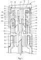
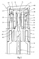
- FIGS. 1 and 2 are views in partial vertical cross section through a fluid dispenser according to the invention, respectively in the rest position and in the depressed position.
- the distributor comprises several constituent elements, namely a reservoir 1 and a dispensing member, which is in the embodiment of a pump, but it could also have been a valve.
- This pump comprises a body 2, a dip tube 3, a differential piston 4, a pusher 5 and a return and pre-compression spring 6.
- the dip tube 3 is here attached to the body 2, but it is also possible to make the dip tube in one piece with the body 2.
- the spring 6 is an independent piece, but it is possible alternatively to make it integrally with the body 2 or the differential piston 4. Therefore, the pump of the invention comprises three to five constituent elements.
- the reservoir 1 is intended to contain fluid product to be dispensed. It can be made of glass, metal or plastic. Its capacity may be of the order of two to three millimeters in the case of samples or may be much higher in the case of conventional tanks.
- the tank can have all the appropriate forms. It comprises a bottom (not shown), a side wall (partially shown), and an opening 10 defined here by a neck 11.
- This neck 11 comprises a peripheral annular groove 12 at its outer wall.
- the neck 11 also comprises an inner wall 14 which will serve to seal with the pump, as will be seen below.
- the neck 11 also defines an upper annular edge 13. Below the neck 11, the reservoir forms an outer shoulder 15 which is directed upwards. This is only a particular embodiment for the tank. In a very general way, it is sufficient that it defines a useful storage volume for the fluid product and an opening through which the fluid can be extracted from the reservoir.
- the pump used to illustrate the present invention is of the "pusher pump” type, which has the particularity that the pusher forms part of the pump chamber generally designated by C. In most cases, the pusher also defines a sliding shaft for the piston.
- the pump body 2 can be made by injection molding of suitable plastic material.
- the body is a piece that presents advantageously a symmetry of revolution around the visible X axis on the figure 1 .
- the body comprises in a very general manner two series of three concentric rings which extend on either side of a radial plate 25 which is traversed at its center by an inlet channel 20.
- the series of three concentric rings which extends downwards from the plate 25 comprises an external fixing ring 21 provided on its inner wall with a fastening cord 22 adapted to snap into the groove 12 of the neck 11.
- the ring 21 is the outermost ring.
- the body 2 comprises a self-sealing cylindrical sleeve 24 which comes into sealing contact with the inner wall 14 of the neck 11.
- the body forms a connecting sleeve 23 inside which is engaged the upper end of the dip tube 3 which extends into the tank 1 to near its bottom.
- the connecting sleeve 23 extends axially forming the inlet conduit 20.
- the ring 21, the sleeve 24 and the sleeve 23 all extend downwards from the annular radial plate 25.
- the self-sealing sleeve 24 will slide sealingly against the inner wall 14 of the neck 11 on a relatively large axial stroke.
- the cord 22 engages snap-fit inside the groove 12. This corresponds to the final mounting position of the body 2, and thus of the pump, on the reservoir.
- the series of three crowns that extend upward from the plate 25 includes an outermost guide sleeve 26 which is located the outermost.
- the guide sleeve 26 defines a shoulder 261 which will act as a stop, as will be seen below.
- the sleeve 26 serves as a bearing surface for the spring 6 which is housed between the sleeve 26 and the barrel 27.
- the body forms a sliding shaft 27 which has an inner wall essentially cylindrical.
- the inner wall of the barrel forms at least one boss or rib which defines a discontinuity 271 in the cylindricity of the barrel. Its function will be given below.
- the body further defines an inlet pipe 28 which internally defines a portion of the inlet conduit 20.
- the free upper end of the pipe 28 forms a sliding sealing bead 281, as will be seen hereinafter.
- the inlet duct 20 thus directly communicate the tubing 28 with the plunger tube 3. It should be noted that there is no system or vent passage between the body and the reservoir.
- the differential piston 4 comprises a hollow axial tube 41 whose free end defines a main piston lip 42 adapted to slide sealingly inside the barrel 27 of the body 2.
- the lip 42 is elastically deformable.
- the differential piston 4 comprises a rod 43 which performs a function of moving member of the inlet valve.
- This rod 43 advantageously defines three sections, namely a lower section 431 of reduced diameter or groove, an intermediate section 432 of maximum diameter and an upper section 433 defined with at least one protruding or hollow profile 434.
- the profile is in the form of one or more grooves which advantageously extend axially.
- the rod 43 is engaged inside the tubing 28 so that the sealing bead 281 is positioned at the reduced diameter lower section 431 when the pump is at rest, as shown in FIG. figure 1 . There is then no sealed contact between the bead 281 and the rod 43.
- the tubing 28, or more precisely its sealing bead 281 cooperates with the rod 43 to form together the inlet valve pump. Therefore, as we have just seen, the inlet valve is open in the rest position, since there is no contact between the cord 281, which serves as an inlet valve seat, and the rod 43, which serves as movable member of the inlet valve.
- the differential piston 4 forms a connecting channel 44 which passes through the tube 41.
- the differential piston 4 forms an annular flange 45 which extends radially outwards.
- this flange 45 forms a differential piston lip 46 and an annular flange 47 which serves as a movable outlet valve member, as will be seen hereinafter.
- the spring 6 bears under the annular flange 45.
- the pusher 5 comprises an upper support plate 51 on which the user can press with the aid of one or more fingers. On its outer periphery, this plate extends downwardly forming a skirt 52, here of substantially cylindrical shape.
- the skirt 52 defines near its upper end where it is connected to the plate 51 an internal distribution wall 53 at which is formed a dispensing orifice 50.
- the wall 53 also forms channels and a swirl chamber 54 centered on the orifice 50.
- the skirt 52 forms a sliding cylinder 55 which has a diameter slightly greater than that of the distribution wall 53.
- the skirt 52 forms an internal stop reinforcement 56 which is housed below the shoulder 261 of the guide sleeve 26.
- the skirt 52 also performs a guiding function by being engaged around the upper part of the sleeve 26.
- the stop reinforcement 56 prevents the withdrawal of the pusher 5 from the body 2 and defines the rest position.
- the plate 51 includes an inner bottom wall that will form a portion of the pump chamber. On the other hand, the plate 51 forms at its outer periphery an outlet valve seat 511, which has a generally frustoconical configuration.
- the differential piston 4 is engaged inside the pusher 5 so that its lip 46 comes into sealing contact with the sliding cylinder 55.
- the collar 47 comes into contact sealed with the seat 511 in the rest position, as shown on the figure 1 .
- the spring 6 urges the differential piston 4 against the plate 51 away from the body 2.
- the tube 41 is engaged inside the barrel 27 and the rod 43 is engaged inside the
- the pump chamber C defines a lower part formed between the barrel 27 and the tubing 28 and an upper part formed between the flange 45 and the plate 51. These two parts communicate with each other through the connecting channel 44. extending through the piston 4.
- the spring 6 which bears on the inner shoulder of the bushing 26 pushes the differential piston 4 away from the body 2. This has the effect of pressing the flange 47 of the piston 4 against the seat 511 of the plate 51.
- the pusher 5 is thus also biased away from the body 2 and the rest position is defined when the abutment reinforcement 56 abuts against the shoulder 261 of the sleeve 26.
- the pump chamber C is then isolated from the outside by the sealing contact between the flange 47 on the seat 511.
- the main piston lip 42 is at its highest position inside the barrel 27.
- the inlet valve it is open, since the cord 281 does not come into sealed contact with the rod 43.
- the pump chamber C then only communicates with the reservoir through the inlet duct 20 and the plunger tube 3.
- the differential piston 4 When axially pressing the push-button 5 from the rest position of the figure 1 , the differential piston 4 is driven axially downwards so that the intermediate section 432 of the rod 43 engages sealingly in the annular bead 281 of the pipe 28.
- the inlet valve is then closed and the chamber C no longer communicates with the tank.
- the pressure rises inside the chamber C, and because of the surface differential between the lower part and the upper part of the chamber, the differential piston 4 moves away from the plate 51, thus opening the valve of outlet formed by the flange 47 and the seat 511.
- the chamber C then communicates with the outside and the pressurized fluid can be dispensed through the orifice 50.
- the outlet valve For the outlet valve to open, it is necessary that the pressure inside the chamber is greater than the force exerted by the spring 6.
- the present invention is particularly interesting, not in the normal operating cycle of the dispenser, but during the mounting phase of the pump on the tank and during the priming phase of the pump. Indeed, when the pump is mounted on the tank, the self-sealing sleeve 23 slides sealingly over a certain stroke against the inner wall 14 of the neck 11. This would normally have the effect of considerably increasing the pressure at the top of the tank. inside the tank, especially when it is of a low capacity. Thanks to the escape routes F1 and F2, the air pressurized inside the tank can escape to the outside by following the arrow path of the figure 2 . In addition, this venting of the tank and the chamber allows easy and automatic priming of the pump.
- the inlet valve will close and the depression that forms inside the chamber will allow to suck fluid in the pump chamber, thus priming the pump.
- This simultaneous operation of venting the tank and priming the chamber can be performed when mounting the pump on the tank using a press that presses the pusher. The force exerted by the press will firstly snap the ring 21 on the neck 11 and secondly put the pump in the depressed position.
- Another interesting feature of the invention lies in the fact that the leak F1 is established before the leak F2, so that the chamber C first communicates with the tank and then only with the outside.
- the pressure prevailing inside the tank will first be balanced with the chamber and the residual pressure is balanced with the outside at atmospheric pressure.
- This phase shift or sequencing of the opening of the escape paths F1 and F2 also makes it possible to avoid any risk of leakage of fluid during normal operation of the dispenser. Indeed, since the escape path F1 opens before the escape path F2, the fluid remaining in the chamber C near the depressed position, when the outlet valve is closed, will be forced to flow to the tank through the F1 escape path, and not through the leakage path F2 which is still closed.
- the pressure in the chamber is no longer sufficient to keep the outlet valve open, but still higher than the pressure in the tank or the atmospheric pressure.
- the opening phase shift can be very simply achieved by providing that the seal between the bead 281 and the rod 43 is broken before the sealing contact between the lip 42 and the barrel is.
- the grooves 434 of the rod can be replaced by any configuration suitable for breaking the seal between the tubing 28 and the rod 43.
- the ribs or bosses 271 formed at the drum can be replaced by any configuration to break the seal with the lip 42.
- the second escape path F2 is separate from the outlet valve, so that the air is forced out of the chamber through the leakage path F2 while the outlet valve is and remains closed.
- venting system of the present invention thus makes it possible not only to avoid any overpressure inside the tank and to prime the pump, but also to avoid any risk of leakage during normal operation of the pump, and this advantageously through the implementation of two separate escape paths whose openings are not simultaneous.
Description
La présente invention concerne un distributeur de produit fluide comprenant un réservoir pourvu d'une ouverture et un organe de distribution, tel qu'une pompe ou une valve, monté dans l'ouverture du réservoir. Ce type de distributeur manuel portatif est fréquemment utilisé dans les domaines de la parfumerie, de la cosmétique ou encore de la pharmacie.The present invention relates to a fluid dispenser comprising a reservoir provided with an opening and a dispensing member, such as a pump or a valve, mounted in the opening of the reservoir. This type of portable manual dispenser is frequently used in the fields of perfumery, cosmetics or even pharmacy.
Dans l'art antérieur, on connaît déjà le document
Le distributeur décrit dans le document
Par conséquent, un premier but de la présente invention est d'atténuer ou d'éliminer cette surpression à l'intérieur du réservoir lors de l'assemblage du distributeur.Therefore, a first object of the present invention is to mitigate or eliminate this pressure inside the tank during assembly of the dispenser.
Un autre problème que l'on rencontre fréquemment avec ce type de distributeur est l'amorçage de la pompe, c'est-à-dire le premier remplissage de la chambre de pompe avec du produit fluide en provenance du réservoir. Initialement, après montage de la pompe sur le réservoir, la chambre de pompe est remplie d'air. En actionnant le poussoir, on fait diminuer le volume de la chambre de pompe et l'air est ainsi comprimé à l'intérieur. Cependant, la pression atteinte à l'intérieur de la chambre n'est souvent pas suffisante pour ouvrir le clapet de sortie de manière à permettre à l'air prisonnier dans la chambre d'être refoulé vers l'extérieur à travers l'orifice de distribution. Il est souvent nécessaire d'actionner plusieurs fois le poussoir pour remplir, c'est-à-dire amorcer, la chambre de pompe. Parfois, l'amorçage n'est même pas possible.Another problem that is frequently encountered with this type of dispenser is the priming of the pump, that is to say the first filling of the pump chamber with fluid from the reservoir. Initially, after mounting the pump on the tank, the pump chamber is filled with air. By actuating the pusher, the volume of the pump chamber is reduced and the air is thus compressed inside. However, the pressure reached inside the chamber is often not sufficient to open the outlet valve so as to allow air trapped in the chamber to be forced out through the orifice of the chamber. distribution. It is often necessary to actuate the pusher several times to fill, that is to say, prime, the pump chamber. Sometimes, booting is not even possible.
Par conséquent, un autre but de la présente invention est de permettre un amorçage aisé et rapide de la chambre de pompe. De préférence, la présente invention doit permettre à la fois une élimination de la surpression régnant dans le réservoir et un amorçage de la pompe au cours d'une seule et même opération simple, que l'on peut facilement mettre en oeuvre lors de l'assemblage du distributeur.Therefore, another object of the present invention is to allow easy and fast priming of the pump chamber. Preferably, the present invention must allow both an elimination of the pressure in the reservoir and a priming of the pump during a single simple operation, which can be easily implemented during the distributor assembly.
Le document
Pour atteindre ces buts, la présente invention propose un distributeur de produit fluide comprenant un réservoir de produit fluide pourvu d'une ouverture, et un organe de distribution, tel qu'une pompe ou une valve, monté sur l'ouverture du réservoir, l'organe formant une chambre de produit fluide pourvue d'un clapet d'entrée, d'un clapet de sortie et d'une lèvre déplaçable à coulissement étanche dans un fût cylindrique entre une position de repos et une position enfoncée pour faire varier le volume de la chambre, et refouler le produit fluide de la chambre à travers le clapet de sortie vers un orifice de distribution, caractérisé en ce que le clapet d'entrée définit, à proximité de la position enfoncée, un premier chemin de fuite qui fait communiquer le réservoir avec la chambre, la chambre communiquant, à proximité de la position enfoncée, avec l'extérieur à travers un second chemin de fuite qui ne passe pas par le clapet de sortie et l'orifice de distribution, de sorte que le réservoir et la chambre communiquent avec l'extérieur, à proximité de la position enfoncée, à travers les premier et second chemins de fuite ouverts avec le clapet de sortie fermé. Ainsi, la surpression régnant dans le réservoir peut être diminuée ou éliminée en communiquant avec la chambre, et l'air comprimé à l'intérieur de la chambre peut s'échapper vers l'extérieur, sans passer à travers le clapet de sortie. Au final, il y a une parfaite compensation des pressions à l'intérieur du distributeur avec la pression atmosphérique.To achieve these objects, the present invention provides a fluid dispenser comprising a fluid reservoir provided with an opening, and a dispensing member, such as a pump or a valve, mounted on the reservoir opening, member forming a fluid product chamber provided with an inlet valve, an outlet valve and a displaceably movable lip in a cylindrical barrel between a position resting position and a depressed position for varying the volume of the chamber, and discharging the fluid product from the chamber through the outlet valve to a dispensing orifice, characterized in that the inlet valve defines, close to the depressed position, a first escape route which makes the tank communicate with the chamber, the communicating chamber, proximity of the depressed position, with the outside through a second leakage path that does not pass through the outlet valve and the dispensing orifice, so that the tank and the chamber communicate with the outside, close to the depressed position, through the first and second vanishing paths open with the closed outlet valve. Thus, the overpressure in the reservoir can be decreased or eliminated by communicating with the chamber, and the compressed air within the chamber can escape outwardly without passing through the outlet valve. In the end, there is a perfect compensation of the pressures inside the distributor with the atmospheric pressure.
Selon une caractéristique avantageuse, le premier chemin de fuite est ouvert avant le second chemin de fuite, de sorte que la chambre communique avec le réservoir avant qu'elle ne communique avec l'extérieur. Ainsi, dans un premier temps, la pression régnant dans le réservoir est égalisée avec la pression régnant dans la chambre, et dans un second temps, la pression commune régnant dans le réservoir et la chambre est égalisée avec l'extérieur. L'établissement des premier et second chemins de fuite s'effectue en amenant le poussoir vers sa position enfoncée. Ceci peut être effectué lors du montage de l'organe de distribution sur l'ouverture du réservoir à l'aide d'une presse appuyant sur le poussoir. La presse commence par enfoncer le poussoir à fond dans la position enfoncée avant de monter l'organe de distribution dans l'ouverture du réservoir. Ainsi, les deux chemins de fuite sont établis avant même qu'une quelconque surpression puisse être générée à l'intérieur du réservoir. En continuant à appuyer sur le poussoir, avec les deux chemins de fuite ouverts, l'organe de distribution est amené en position de montage final dans l'ouverture du réservoir. La presse relâche alors sa pression sur le poussoir qui revient vers sa position de repos. Lors de cette phase de retour, le second chemin de fuite est fermé avant le premier chemin de fuite. Ensuite, le clapet d'entrée remplit sa fonction normale, créant une dépression à l'intérieur de la chambre qui va permettre d'aspirer du produit fluide en provenance du réservoir. L'organe de distribution est ainsi amorcé dès son montage sur le réservoir. De plus, toute surpression à l'intérieur du réservoir est empêchée.According to an advantageous characteristic, the first escape path is open before the second escape path, so that the chamber communicates with the reservoir before it communicates with the outside. Thus, in a first step, the pressure in the reservoir is equalized with the pressure prevailing in the chamber, and in a second step, the common pressure in the reservoir and the chamber is equalized with the outside. The establishment of the first and second escape paths is effected by bringing the pusher to its depressed position. This can be done when mounting the dispenser member on the opening of the tank with a press pressing the pusher. The press begins by pushing the pusher fully into the depressed position before mounting the dispensing member in the opening of the tank. Thus, the two escape routes are established before any overpressure can be generated inside the tank. Continuing to press the pusher, with both escape paths open, the dispensing member is brought into the final mounting position in the opening of the reservoir. The press then releases its pressure on the pusher returning to its rest position. During this return phase, the second escape route is closed before the first escape route. Then, the inlet valve performs its normal function, creating a vacuum inside the chamber that will allow to draw fluid from the tank. The dispensing member is thus initiated as soon as it is mounted on the reservoir. In addition, any overpressure inside the tank is prevented.
D'autre part, en fonctionnement normal, c'est-à-dire après amorçage de l'organe de distribution, le déphasage d'établissement ou d'ouverture des chemins de fuite permet d'éliminer tout risque de fuite de produit fluide hors de la chambre. En effet, étant donné que le premier chemin de fuite est ouvert avant le second chemin de fuite, du produit fluide sous pression à l'intérieur de la chambre C en fin de course du poussoir serait refoulé à travers le premier chemin de fuite en direction du réservoir, et non à travers le second chemin de fuite qui ne va s'ouvrir qu'ultérieurement. C'est donc ce séquençage temporel des ouvertures de chemin de fuite qui permet d'éviter tout risque de fuite de produit fluide au cours du fonctionnement normal du distributeur.On the other hand, in normal operation, that is to say after ignition of the dispensing member, the phase shift of establishment or opening of the escape paths makes it possible to eliminate any risk of leakage of fluid product out from the room. Indeed, since the first leakage path is open before the second leakage path, pressurized fluid inside chamber C at the end of the stroke of the plunger would be forced through the first leak path in the direction of flow. of the tank, and not through the second escape route which will only open later. It is therefore this temporal sequencing of the escape route openings that makes it possible to avoid any risk of leakage of fluid during normal operation of the dispenser.
Selon une forme de réalisation pratique, la lèvre rompt son coulissement étanche avec le fût cylindrique à proximité de la position enfoncée pour établir le second chemin de fuite. De préférence, le fût forme au moins une discontinuité sur laquelle passe la lèvre, créant ainsi le second chemin de fuite. La fonction de la ou des discontinuité(s) est de décoller au moins localement la lèvre du fût pour créer un défaut d'étanchéité qui va servir de chemin de fuite pour l'air sous pression.According to a practical embodiment, the lip breaks its tight sliding with the cylindrical barrel near the depressed position to establish the second escape path. Preferably, the barrel forms at least one discontinuity on which the lip passes, thus creating the second escape path. The function of the discontinuity (s) is to take off at least locally the lip of the barrel to create a leakage that will serve as a leakage path for pressurized air.
Selon un autre aspect pratique de l'invention, le clapet d'entrée comprend deux éléments engagés à coulissement étanche l'un dans l'autre, sauf en position de repos dans laquelle le clapet est ouvert et à proximité de la position enfoncée pour établir le premier chemin de fuite. Avantageusement, un des éléments forme au moins un profil sur lequel passe l'autre élément, créant ainsi le premier chemin de fuite. Là encore, la fonction du ou des profil(s) est de créer un défaut local d'étanchéité servant de chemin de fuite pour l'air sous pression et éventuellement pour le produit fluide sous pression.According to another practical aspect of the invention, the inlet valve comprises two elements engaged to slide one inside the other, except in the rest position in which the valve is open and close to the depressed position to establish the first escape route. Advantageously, one of the elements forms at least one profile over which the other element passes, thus creating the first escape route. Again, the function of the profile (s) is to create a local leakage leakage path for the pressurized air and possibly for the fluid under pressure.
Selon une forme de réalisation pratique, l'organe de distribution comprend un corps destiné à être monté sur l'ouverture du réservoir, le corps formant le fût cylindrique, un poussoir déplaçable axialement en va-et-vient sur le corps entre les positions de repos et enfoncée, un piston différentiel comprenant une première lèvre engagée à coulissement étanche dans le fût du corps et seconde lèvre engagée à coulissement étanche dans le poussoir. Avantageusement, le corps forme une tubulure d'entrée et le piston différentiel forme une tige engagée à coulissement étanche dans la tubulure de manière à définir ensemble le clapet d'entrée, la tige format au moins un profil au niveau duquel la tubulure n'est pas en contact étanche, établissant ainsi le premier chemin de fuite. Selon un autre aspect avantageux, l'organe de distribution comprend un ressort qui sollicite le piston différentiel vers le poussoir en éloignement du corps. Selon une autre caractéristique avantageuse, l'organe de distribution comprend une manchette auto-jointante qui vient en contact de coulissement étanche avec l'ouverture du réservoir lors du montage de l'organe de distribution sur le réservoir.According to a practical embodiment, the dispensing member comprises a body intended to be mounted on the opening of the reservoir, the body forming the cylindrical barrel, an axially displaceable pusher back and forth on the body between the rest and depressed positions, a differential piston comprising a first lip slidably engaged in the barrel of the body and second lip slidably engaged in the pusher. Advantageously, the body forms an inlet pipe and the differential piston forms a rod which is slidably engaged in the pipe in such a way as to define together the inlet valve, the rod forms at least one profile at the level of which the pipe is not not in sealed contact, thus establishing the first escape route. According to another advantageous aspect, the dispenser member comprises a spring which urges the differential piston toward the pusher away from the body. According to another advantageous characteristic, the dispensing member comprises a self-sealing sleeve which comes into sealing contact with the opening of the reservoir during assembly of the dispensing member on the reservoir.
C'est la course de contact étanche de la manchette dans l'ouverture du réservoir qui emprisonnerait de l'air à l'intérieur du réservoir et ferait monter considérablement sa pression en l'absence des deux chemins de fuite établis selon l'invention.It is the race of sealed contact of the sleeve in the opening of the tank which would trap air inside the tank and would increase considerably its pressure in the absence of the two escape routes established according to the invention.
La présente invention résout à la fois le problème de surpression dans le réservoir et le problème de l'amorçage de l'organe de distribution, sans pour autant créer un risque de fuite de produit fluide. La présente invention s'applique de préférence aux pompes, mais peut également s'appliquer aux valves. De même, elle s'applique de préférence aux distributeurs de faible contenance tels que les échantillons, mais peut également s'appliquer à tout autre distributeur de contenance supérieure.The present invention solves both the problem of overpressure in the tank and the problem of the priming of the dispensing member, without creating a risk of fluid leakage. The present invention is preferably applied to pumps, but can also be applied to valves. Similarly, it applies preferably to small capacity dispensers such as samples, but can also be applied to any other dispenser of higher capacity.
L'invention sera maintenant plus amplement décrite en référence aux dessins joints donnant à titre d'exemple non limitatif un mode de réalisation de l'invention.The invention will now be more fully described with reference to the accompanying drawings giving by way of non-limiting example an embodiment of the invention.
Les
On se réfèrera indifféremment aux
Le réservoir 1 est destiné à contenir du produit fluide à distribuer. Il peut être réalisé en verre, en métal ou en matière plastique. Sa contenance peut être de l'ordre de deux à trois millimètres dans le cas d'échantillons ou peut être bien supérieur dans le cas de réservoirs conventionnels. Le réservoir peut présenter toutes les formes appropriées. Il comprend un fond (non représenté), une paroi latérale (partiellement représentée), et une ouverture 10 définie ici par un col 11. Ce col 11 comprend une rainure annulaire périphérique 12 au niveau de sa paroi externe. Le col 11 comprend également une paroi interne 14 qui va servir à réaliser l'étanchéité avec la pompe, comme on le verra ci-après. Le col 11 définit également un bord annulaire supérieur 13. En dessous du col 11, le réservoir forme un épaulement extérieur 15 qui est orienté vers le haut. Il ne s'agit là que d'une forme particulière de réalisation pour le réservoir. De manière très générale, il suffit qu'il définisse un volume utile de stockage pour du produit fluide et une ouverture par laquelle le produit fluide peut être extrait du réservoir.The
La pompe utilisée pour illustrer la présente invention est du type « pompe poussoir », qui a ceci de particulier que le poussoir forme une partie de la chambre de pompe désignée dans son ensemble par C. Dans la plupart des cas, le poussoir définit également un fût de coulissement pour le piston.The pump used to illustrate the present invention is of the "pusher pump" type, which has the particularity that the pusher forms part of the pump chamber generally designated by C. In most cases, the pusher also defines a sliding shaft for the piston.
Le corps de pompe 2 peut être réalisé par injection moulage de matière plastique appropriée. Le corps est une pièce qui présente avantageusement une symétrie de révolution autour de l'axe X visible sur la
Plus précisément, la série de trois couronnes concentriques qui s'étend vers le bas à partir du plateau 25 comprend une bague de fixation externe 21 pourvue sur sa paroi interne d'un cordon d'accrochage 22 adapté à venir s'encliqueter dans la rainure 12 du col 11. La bague 21 est la couronne située la plus à l'extérieur. A l'intérieur de cette bague 21, le corps 2 comprend une manchette cylindrique auto-jointante 24 qui vient en contact étanche avec la paroi interne 14 du col 11. A l'intérieur de cette manchette 24, le corps forme un manchon de raccordement 23 à l'intérieur duquel est engagée l'extrémité supérieure du tube plongeur 3 qui s'étend dans le réservoir 1 jusqu'à proximité de son fond. Le manchon de raccordement 23 se prolonge axialement en formant le conduit d'entrée 20. La bague 21, la manchette 24 et le manchon 23 s'étendent tous vers le bas à partir du plateau radial annulaire 25. Lors du montage du corps 2 sur le col 11 du réservoir, la manchette auto-jointante 24 va coulisser de manière étanche contre la paroi interne 14 du col 11 sur une course axiale relativement importante. En fin de course, le cordon 22 s'engage par encliquetage à l'intérieur de la rainure 12. Ceci correspond à la position finale de montage du corps 2, et ainsi de la pompe, sur le réservoir.More specifically, the series of three concentric rings which extends downwards from the
La série de trois couronnes qui s'étendent vers le haut à partir du plateau 25 comprend une douille externe de guidage 26 qui est située la plus à l'extérieur. La douille de guidage 26 définit un épaulement vers le bas 261 qui va servir de butée, comme on le verra ci-après. Intérieurement, la douille 26 sert de surface d'appui pour le ressort 6 qui est logé entre la douille 26 et le fût 27. A l'intérieur de cette douille 26, le corps forme un fût de coulissement 27 qui présente une paroi interne essentiellement cylindrique. Selon l'invention, la paroi interne du fût forme au moins un bossage ou une nervure qui définit une discontinuité 271 dans la cylindricité du fût. Sa fonction sera donnée ci-après. A l'intérieur du fût 27, le corps définit en outre une tubulure d'entrée 28 qui définit intérieurement une partie du conduit d'entrée 20. L'extrémité supérieure libre de la tubulure 28 forme un cordon d'étanchéité coulissant 281, comme on le verra ci-après.The series of three crowns that extend upward from the
Le conduit d'entrée 20 fait ainsi directement communiquer la tubulure 28 avec le tube plongeur 3. Il faut noter qu'il n'y a aucun système ou passage d'éventation entre le corps et le réservoir.The
Le piston différentiel 4 comprend un tube axial creux 41 dont l'extrémité libre définit une lèvre de piston principal 42 adaptée à coulisser de manière étanche à l'intérieur du fût 27 du corps 2. Avantageusement, la lèvre 42 est élastiquement déformable. A l'intérieur du tube 41, le piston différentiel 4 comprend une tige 43 qui remplit une fonction d'organe mobile de clapet d'entrée. Cette tige 43 définit avantageusement trois sections, à savoir une section inférieure 431 de diamètre réduit ou rainure, une section intermédiaire 432 de diamètre maximal et une section supérieure 433 définie avec au moins un profil saillant ou en creux 434. Sur les figures, le profil se présente sous la forme d'une ou de plusieurs rainures qui s'étendent avantageusement axialement. La tige 43 est engagée à l'intérieur de la tubulure 28 de telle sorte que le cordon d'étanchéité 281 est positionné au niveau de la section inférieure de diamètre réduit 431 lorsque la pompe est au repos, comme représenté sur la
D'autre part, le piston différentiel 4 forme un canal de liaison 44 qui traverse le tube 41. A son extrémité supérieure, le piston différentiel 4 forme une bride annulaire 45 qui s'étend radialement vers l'extérieur. Sur sa périphérie extérieure, cette bride 45 forme une lèvre de piston différentiel 46 ainsi qu'une collerette annulaire 47 qui sert d'organe mobile de clapet de sortie, comme on le verra ci-après. Le ressort 6 prend appui sous la bride annulaire 45.On the other hand, the
Le poussoir 5 comprend un plateau supérieur d'appui 51 sur lequel l'utilisateur peut appuyer à l'aide d'un ou de plusieurs doigts. Sur sa périphérie extérieure, ce plateau se prolonge vers le bas en formant une jupe 52, ici de forme sensiblement cylindrique. La jupe 52 définit à proximité de son extrémité supérieure où elle se raccorde au plateau 51 une paroi de distribution interne 53 au niveau de laquelle est formé un orifice de distribution 50. Selon une forme de réalisation avantageuse, la paroi 53 forme également des canaux et une chambre de tourbillonnement 54 centrés sur l'orifice 50. En dessous de la paroi de distribution 53, la jupe 52 forme un cylindre de coulissement 55 qui présente un diamètre légèrement supérieur à celui de la paroi de distribution 53. A son extrémité inférieure, la jupe 52 forme un renfort de butée interne 56 qui vient se loger en dessous de l'épaulement 261 de la douille de guidage 26. La jupe 52 remplit d'ailleurs une fonction de guidage en étant engagée autour de la partie supérieure de la douille de guidage 26. Le renfort de butée 56 empêche le retrait du poussoir 5 à partir du corps 2 et définit la position de repos. Le plateau 51 comprend une paroi inférieure interne qui va former une partie de la chambre de pompe. D'autre part, le plateau 51 forme au niveau de sa périphérie externe un siège de clapet de sortie 511, qui présente une configuration globalement tronconique.The
Le piston différentiel 4 est engagé à l'intérieur du poussoir 5 de telle sorte que sa lèvre 46 vient en contact de coulissement étanche avec le cylindre de coulissement 55. D'autre part, la collerette 47 vient en contact étanche avec le siège 511 en position de repos, comme représenté sur la
Nous allons maintenant décrire un cycle complet de fonctionnement normal de ce distributeur depuis sa position de repos jusqu'à sa position enfoncée représentée sur la
En position de repos, le ressort 6 qui prend appui sur l'épaulement interne de la douille 26 pousse le piston différentiel 4 en éloignement du corps 2. Ceci a pour effet d'appuyer la collerette 47 du piston 4 contre le siège 511 du plateau 51. Le poussoir 5 est ainsi également sollicité en éloignement du corps 2 et la position de repos est définie lorsque le renfort de butée 56 vient en butée contre l'épaulement 261 de la douille 26. La chambre de pompe C est alors isolée de l'extérieur par le contact étanche entre la collerette 47 sur le siège 511. D'autre part, la lèvre de piston principal 42 est à sa position la plus haute à l'intérieur du fût 27. Quant au clapet d'entrée, il est ouvert, puisque le cordon 281 ne vient pas en contact étanche avec la tige 43. La chambre de pompe C communique alors seulement avec le réservoir à travers le conduit d'entrée 20 et le tube plongeur 3.In the rest position, the
Lorsque l'on appuie axialement sur le poussoir 5 à partir de la position de repos de la
En continuant à appuyer sur le poussoir, on parvient à la position enfoncée représentée sur la
En relâchant la pression exercée sur le poussoir, le piston différentiel va remonter sous l'action du ressort 6. La lèvre 42 va à nouveau regagner sa position de contact étanche dans le fût 27 et le clapet d'entrée va se refermer. Une dépression va se former à l'intérieur de la chambre C et lorsque le clapet va de nouveau retourner dans sa position de repos de la
La présente invention est particulièrement intéressante, non pas dans le cycle normal de fonctionnement du distributeur, mais lors de la phase de montage de la pompe sur le réservoir et lors de la phase d'amorçage de la pompe. En effet, lorsque l'on monte la pompe sur le réservoir, la manchette auto-jointante 23 coulisse de manière étanche sur une certaine course contre la paroi interne 14 du col 11. Ceci aurait normalement pour effet d'augmenter considérablement la pression à l'intérieur du réservoir, particulièrement lorsque celui-ci est d'une contenance faible. Grâce aux chemins de fuite F1 et F2, l'air mis sous pression à l'intérieur du réservoir peut s'échapper vers l'extérieur en suivant le parcours fléché de la
Une autre caractéristique intéressante de l'invention réside dans le fait que la fuite F1 est établie avant la fuite F2, de sorte que la chambre C communique d'abord avec le réservoir puis seulement ensuite avec l'extérieur. En d'autres termes, la surpression régnant à l'intérieur du réservoir va d'abord être équilibrée avec la chambre puis la surpression résiduelle est équilibrée avec l'extérieur à la pression atmosphérique. Ce déphasage ou séquençage de l'ouverture des chemins de fuite F1 et F2 permet d'autre part d'éviter tout risque de fuite de produit fluide au cours du fonctionnement normal du distributeur. En effet, puisque le chemin de fuite F1 s'ouvre avant le chemin de fuite F2, le produit fluide restant dans la chambre C à proximité de la position enfoncée, lorsque le clapet de sortie est fermé, sera contraint de s'écouler vers le réservoir à travers le chemin de fuite F1, et non pas à travers le chemin de fuite F2 qui est encore fermé. La pression dans la chambre n'est plus suffisante pour maintenir le clapet de sortie ouvert, mais tout de même supérieure à la pression régnant dans le réservoir ou la pression atmosphérique. Le déphasage d'ouverture peut être très simplement réalisé en prévoyant que l'étanchéité entre le cordon 281 et la tige 43 est rompu avant que le contact étanche entre la lèvre 42 et la fût ne le soit. On peut très simplement jouer sur la hauteur des nervures et/ou rainures permettant d'établir les chemins de fuite. Bien entendu, les rainures 434 de la tige peuvent être remplacées par n'importe quelle configuration appropriée permettant de rompre l'étanchéité entre la tubulure 28 et la tige 43. De même, les nervures ou bossages 271 formés au niveau du fût peuvent être remplacés par n'importe quelle configuration permettant de rompre l'étanchéité avec la lèvre 42.Another interesting feature of the invention lies in the fact that the leak F1 is established before the leak F2, so that the chamber C first communicates with the tank and then only with the outside. In other words, the pressure prevailing inside the tank will first be balanced with the chamber and the residual pressure is balanced with the outside at atmospheric pressure. This phase shift or sequencing of the opening of the escape paths F1 and F2 also makes it possible to avoid any risk of leakage of fluid during normal operation of the dispenser. Indeed, since the escape path F1 opens before the escape path F2, the fluid remaining in the chamber C near the depressed position, when the outlet valve is closed, will be forced to flow to the tank through the F1 escape path, and not through the leakage path F2 which is still closed. The pressure in the chamber is no longer sufficient to keep the outlet valve open, but still higher than the pressure in the tank or the atmospheric pressure. The opening phase shift can be very simply achieved by providing that the seal between the
Il faut bien remarquer que le second chemin de fuite F2 est distinct du clapet de sortie, de sorte que l'air est refoulé hors de la chambre à travers le chemin de fuite F2 alors que le clapet de sortie est et reste fermé.It should be noted that the second escape path F2 is separate from the outlet valve, so that the air is forced out of the chamber through the leakage path F2 while the outlet valve is and remains closed.
Le système d'éventation de la présente invention permet ainsi non seulement d'éviter toute surpression à l'intérieur du réservoir et d'amorcer la pompe, mais également d'éviter tout risque de fuite lors du fonctionnement normal de la pompe, et ceci avantageusement grâce à la mise en oeuvre de deux chemins de fuite distincts dont les ouvertures ne sont pas simultanées.The venting system of the present invention thus makes it possible not only to avoid any overpressure inside the tank and to prime the pump, but also to avoid any risk of leakage during normal operation of the pump, and this advantageously through the implementation of two separate escape paths whose openings are not simultaneous.
Claims (10)
- A fluid dispenser comprising:· a fluid reservoir (1) provided with an opening (10); and· a dispenser member (2, 3, 4, 5, 6), such as a pump or a valve, mounted on the opening (10) of the reservoir, the member forming a fluid chamber (C) that is provided with an inlet valve (28, 43), an outlet valve (47, 511), and a lip (42) that is movable in leaktight sliding in a cylinder (27) between a rest position and a depressed position, so as to cause the volume of the chamber (C) to vary, and the fluid in the chamber to be driven through the outlet valve towards a dispenser orifice (50);
in the proximity of the depressed position, the inlet valve defines a first escape path (F1) that puts the reservoir (1) into communication with the chamber (C),
said dispenser being characterized in that the chamber, in the proximity of the depressed position, communicates with the outside through a second escape path (F2) that does not passe via the outlet valve and the dispenser orifice so that, in the proximity of the depressed position, the reservoir (1) and the chamber communicate with the outside through the open first and second escape paths (F1 and F2), and with the outlet valve closed. - A dispenser according to claim 1, wherein the first escape path (F1) is opened before the second escape path (F2) so that the chamber (C) communicates with the reservoir (1) before it communicates with the outside.
- A dispenser according to claim 1 or claim 2, wherein the sliding of the lip (42) against the cylinder (27) ceases to be leaktight in the proximity of the depressed position, so as to establish the second escape path (F2).
- A dispenser according to claim 3, wherein the cylinder (27) forms at least one discontinuity (271) over which the lip (42) passes, thereby creating the second escape path (F2).
- A dispenser according to any preceding claim, wherein the inlet valve comprises two elements (28, 43) that are engaged to slide in leaktight manner one inside the other, except in the rest position in which the valve is open, and in the proximity of the depressed position so as to establish the first escape path (F1).
- A dispenser according to claim 5, wherein one (43) of the elements forms at least one profile (433) over which the other element (28) passes, thereby creating the first escape path (F2).
- A dispenser according to any preceding claim, wherein the dispenser member comprises:· a body (2) for mounting on the opening (10) of the reservoir (1), the body forming the cylinder (27);· a pusher (5) that is axially movable down and up on the body (2) between the rest position and the depressed position; and· a differential piston (4) including a first lip (42) that is engaged to slide in leaktight manner in the cylinder (27) of the body, and a second lip (46) that is engaged to slide in leaktight manner in the pusher (5).
- A dispenser according to claim 7, wherein the body (2) forms an inlet pipe (28), and the differential piston (4) forms a rod (43) that is engaged to slide in leaktight manner in the pipe (28) in such a manner as to co-operate to define the inlet valve, the rod forming at least one profile (434) where the pipe (28) is not in leaktight contact, thereby establishing the first escape path (F1).
- A dispenser according to claim 7 or claim 8, wherein the dispenser member includes a spring (6) that urges the differential piston (4) towards the pusher (5), away from the body (2).
- A dispenser according to any preceding claim, wherein the dispenser member includes a self-sealing cuff (24) that comes into leaktight sliding contact with the opening (10) of the reservoir (1) while the dispenser member is being mounted on the reservoir.
Applications Claiming Priority (2)
| Application Number | Priority Date | Filing Date | Title |
|---|---|---|---|
| FR0754117A FR2914286B1 (en) | 2007-03-29 | 2007-03-29 | FLUID PRODUCT DISPENSER |
| PCT/FR2008/050544 WO2008132413A2 (en) | 2007-03-29 | 2008-03-28 | Fluid product distributor |
Publications (2)
| Publication Number | Publication Date |
|---|---|
| EP2139606A2 EP2139606A2 (en) | 2010-01-06 |
| EP2139606B1 true EP2139606B1 (en) | 2014-01-08 |
Family
ID=38738906
Family Applications (1)
| Application Number | Title | Priority Date | Filing Date |
|---|---|---|---|
| EP08788070.4A Active EP2139606B1 (en) | 2007-03-29 | 2008-03-28 | Fluid product distributor |
Country Status (6)
| Country | Link |
|---|---|
| US (1) | US8763864B2 (en) |
| EP (1) | EP2139606B1 (en) |
| BR (1) | BRPI0809497B1 (en) |
| ES (1) | ES2452483T3 (en) |
| FR (1) | FR2914286B1 (en) |
| WO (1) | WO2008132413A2 (en) |
Families Citing this family (3)
| Publication number | Priority date | Publication date | Assignee | Title |
|---|---|---|---|---|
| FR2917650B1 (en) * | 2007-06-20 | 2011-03-18 | Valois Sas | METHOD AND DEVICE FOR PACKAGING FLUID PRODUCT DISPENSER |
| FR3005431B1 (en) | 2013-05-13 | 2017-10-06 | Aptar France Sas | FLUID PRODUCT DISPENSER. |
| USD745583S1 (en) * | 2013-10-17 | 2015-12-15 | Foseco International Limited | Fluid distribution device |
Family Cites Families (11)
| Publication number | Priority date | Publication date | Assignee | Title |
|---|---|---|---|---|
| FR2396182A1 (en) * | 1977-07-01 | 1979-01-26 | Normos Norbert | MANUAL PUMP WITH ACCUMULATION OVERCOMPRESSION |
| AU534828B2 (en) * | 1979-05-16 | 1984-02-16 | Yoshino Kogosho Co. Ltd. | Atomizer |
| JPS61905Y2 (en) * | 1979-06-28 | 1986-01-13 | ||
| FR2626253B1 (en) * | 1988-01-26 | 1990-05-18 | Aerosol Bouchage Ste Fse | PREPRESSURE PUMP |
| FR2652389B1 (en) * | 1989-09-26 | 1992-12-04 | Debard Andre | IMPROVEMENT IN PRE-PRESSURE PUMPS FOR THE DISTRIBUTION OF A LIQUID. |
| US5423459A (en) * | 1994-07-25 | 1995-06-13 | Newburgh Mfg Corporation | Continuous spray pump dispenser |
| US5626264A (en) * | 1996-08-09 | 1997-05-06 | Calmar Inc. | Precompression pump sprayer |
| FR2825348B1 (en) * | 2001-06-01 | 2003-08-15 | Daniel Crosnier | METERING PUMP |
| US7789274B2 (en) * | 2003-12-22 | 2010-09-07 | Valois S.A.S | Fluid dispenser member |
| WO2005070560A1 (en) * | 2003-12-22 | 2005-08-04 | Valois Sas | Fluid product dispensing member and dispenser comprising one such member |
| FR2864046B1 (en) * | 2003-12-22 | 2006-12-01 | Valois Sas | FLUID PRODUCT DISPENSING MEMBER. |
-
2007
- 2007-03-29 FR FR0754117A patent/FR2914286B1/en not_active Expired - Fee Related
-
2008
- 2008-03-28 US US12/593,215 patent/US8763864B2/en active Active
- 2008-03-28 ES ES08788070.4T patent/ES2452483T3/en active Active
- 2008-03-28 BR BRPI0809497A patent/BRPI0809497B1/en not_active IP Right Cessation
- 2008-03-28 WO PCT/FR2008/050544 patent/WO2008132413A2/en active Application Filing
- 2008-03-28 EP EP08788070.4A patent/EP2139606B1/en active Active
Also Published As
| Publication number | Publication date |
|---|---|
| BRPI0809497A8 (en) | 2016-02-10 |
| WO2008132413A2 (en) | 2008-11-06 |
| BRPI0809497B1 (en) | 2019-10-22 |
| FR2914286B1 (en) | 2011-09-30 |
| EP2139606A2 (en) | 2010-01-06 |
| US20100108720A1 (en) | 2010-05-06 |
| FR2914286A1 (en) | 2008-10-03 |
| BRPI0809497A2 (en) | 2014-09-23 |
| WO2008132413A3 (en) | 2008-12-24 |
| ES2452483T3 (en) | 2014-04-01 |
| US8763864B2 (en) | 2014-07-01 |
Similar Documents
| Publication | Publication Date | Title |
|---|---|---|
| EP1814672B1 (en) | Flexible part forming an output valve and a return spring for a dispensing device | |
| EP0623060A1 (en) | Improved precompression pump. | |
| LU83122A1 (en) | DISTRIBUTOR | |
| EP2838667B1 (en) | Container for a fluid product, and dispenser using such a container | |
| FR2999960A1 (en) | RECHARGEABLE FLUID PRODUCT DISPENSER. | |
| CA2256789A1 (en) | Conditioning and distribution device comprising an air-vacuum-tank and manufacturing process | |
| EP1701799B1 (en) | Fluid product dispensing member and dispenser comprising one such member | |
| EP2977110B1 (en) | Refillable fluid product dispenser | |
| EP2069076B1 (en) | Device for dispensing a fluid product | |
| EP2988880B1 (en) | Fluid product dispenser | |
| EP2139606B1 (en) | Fluid product distributor | |
| EP2069077B1 (en) | Fluid product dispensing device | |
| EP2178649B1 (en) | Fluid product dispensing member | |
| WO2014184483A1 (en) | Fluid product dispenser | |
| FR3003479A1 (en) | RECHARGEABLE FLUID PRODUCT DISPENSER. | |
| EP3609623B1 (en) | Refillable fluid product dispenser | |
| FR2877325A1 (en) | Viscous fluid product e.g. lotion, dispensing unit e.g. pump, for e.g. cosmetic field, has elastically deformable part formed by monoblock part forming rigid part displaced axially in to and fro manner by deforming deformable part | |
| EP1703985B1 (en) | Fluid product dispenser | |
| FR3003480A1 (en) | RECHARGEABLE FLUID PRODUCT DISPENSER. | |
| WO2022069808A1 (en) | Dispensing device with a hard-spot check valve | |
| FR2974792A1 (en) | FLUID PRODUCT DISPENSER. | |
| EP3408034A1 (en) | Refillable fluid product dispenser. |
Legal Events
| Date | Code | Title | Description |
|---|---|---|---|
| PUAI | Public reference made under article 153(3) epc to a published international application that has entered the european phase |
Free format text: ORIGINAL CODE: 0009012 |
|
| 17P | Request for examination filed |
Effective date: 20091027 |
|
| AK | Designated contracting states |
Kind code of ref document: A2 Designated state(s): AT BE BG CH CY CZ DE DK EE ES FI FR GB GR HR HU IE IS IT LI LT LU LV MC MT NL NO PL PT RO SE SI SK TR |
|
| 17Q | First examination report despatched |
Effective date: 20100305 |
|
| R17C | First examination report despatched (corrected) |
Effective date: 20100412 |
|
| RIN1 | Information on inventor provided before grant (corrected) |
Inventor name: DUQUET, FREDERIC |
|
| DAX | Request for extension of the european patent (deleted) | ||
| RAP1 | Party data changed (applicant data changed or rights of an application transferred) |
Owner name: APTAR FRANCE SAS |
|
| GRAP | Despatch of communication of intention to grant a patent |
Free format text: ORIGINAL CODE: EPIDOSNIGR1 |
|
| INTG | Intention to grant announced |
Effective date: 20130730 |
|
| GRAS | Grant fee paid |
Free format text: ORIGINAL CODE: EPIDOSNIGR3 |
|
| GRAA | (expected) grant |
Free format text: ORIGINAL CODE: 0009210 |
|
| AK | Designated contracting states |
Kind code of ref document: B1 Designated state(s): AT BE BG CH CY CZ DE DK EE ES FI FR GB GR HR HU IE IS IT LI LT LU LV MC MT NL NO PL PT RO SE SI SK TR |
|
| REG | Reference to a national code |
Ref country code: GB Ref legal event code: FG4D Free format text: NOT ENGLISH |
|
| REG | Reference to a national code |
Ref country code: CH Ref legal event code: EP |
|
| REG | Reference to a national code |
Ref country code: IE Ref legal event code: FG4D Free format text: LANGUAGE OF EP DOCUMENT: FRENCH |
|
| REG | Reference to a national code |
Ref country code: AT Ref legal event code: REF Ref document number: 648348 Country of ref document: AT Kind code of ref document: T Effective date: 20140215 |
|
| REG | Reference to a national code |
Ref country code: DE Ref legal event code: R096 Ref document number: 602008029807 Country of ref document: DE Effective date: 20140220 |
|
| REG | Reference to a national code |
Ref country code: ES Ref legal event code: FG2A Ref document number: 2452483 Country of ref document: ES Kind code of ref document: T3 Effective date: 20140401 |
|
| REG | Reference to a national code |
Ref country code: AT Ref legal event code: MK05 Ref document number: 648348 Country of ref document: AT Kind code of ref document: T Effective date: 20140108 |
|
| REG | Reference to a national code |
Ref country code: NL Ref legal event code: VDEP Effective date: 20140108 |
|
| REG | Reference to a national code |
Ref country code: LT Ref legal event code: MG4D |
|
| PG25 | Lapsed in a contracting state [announced via postgrant information from national office to epo] |
Ref country code: LT Free format text: LAPSE BECAUSE OF FAILURE TO SUBMIT A TRANSLATION OF THE DESCRIPTION OR TO PAY THE FEE WITHIN THE PRESCRIBED TIME-LIMIT Effective date: 20140108 Ref country code: NO Free format text: LAPSE BECAUSE OF FAILURE TO SUBMIT A TRANSLATION OF THE DESCRIPTION OR TO PAY THE FEE WITHIN THE PRESCRIBED TIME-LIMIT Effective date: 20140408 Ref country code: IS Free format text: LAPSE BECAUSE OF FAILURE TO SUBMIT A TRANSLATION OF THE DESCRIPTION OR TO PAY THE FEE WITHIN THE PRESCRIBED TIME-LIMIT Effective date: 20140508 |
|
| PG25 | Lapsed in a contracting state [announced via postgrant information from national office to epo] |
Ref country code: AT Free format text: LAPSE BECAUSE OF FAILURE TO SUBMIT A TRANSLATION OF THE DESCRIPTION OR TO PAY THE FEE WITHIN THE PRESCRIBED TIME-LIMIT Effective date: 20140108 Ref country code: FI Free format text: LAPSE BECAUSE OF FAILURE TO SUBMIT A TRANSLATION OF THE DESCRIPTION OR TO PAY THE FEE WITHIN THE PRESCRIBED TIME-LIMIT Effective date: 20140108 Ref country code: CY Free format text: LAPSE BECAUSE OF FAILURE TO SUBMIT A TRANSLATION OF THE DESCRIPTION OR TO PAY THE FEE WITHIN THE PRESCRIBED TIME-LIMIT Effective date: 20140108 Ref country code: PT Free format text: LAPSE BECAUSE OF FAILURE TO SUBMIT A TRANSLATION OF THE DESCRIPTION OR TO PAY THE FEE WITHIN THE PRESCRIBED TIME-LIMIT Effective date: 20140508 Ref country code: SE Free format text: LAPSE BECAUSE OF FAILURE TO SUBMIT A TRANSLATION OF THE DESCRIPTION OR TO PAY THE FEE WITHIN THE PRESCRIBED TIME-LIMIT Effective date: 20140108 Ref country code: NL Free format text: LAPSE BECAUSE OF FAILURE TO SUBMIT A TRANSLATION OF THE DESCRIPTION OR TO PAY THE FEE WITHIN THE PRESCRIBED TIME-LIMIT Effective date: 20140108 |
|
| PG25 | Lapsed in a contracting state [announced via postgrant information from national office to epo] |
Ref country code: HR Free format text: LAPSE BECAUSE OF FAILURE TO SUBMIT A TRANSLATION OF THE DESCRIPTION OR TO PAY THE FEE WITHIN THE PRESCRIBED TIME-LIMIT Effective date: 20140108 Ref country code: LV Free format text: LAPSE BECAUSE OF FAILURE TO SUBMIT A TRANSLATION OF THE DESCRIPTION OR TO PAY THE FEE WITHIN THE PRESCRIBED TIME-LIMIT Effective date: 20140108 |
|
| REG | Reference to a national code |
Ref country code: DE Ref legal event code: R097 Ref document number: 602008029807 Country of ref document: DE |
|
| PG25 | Lapsed in a contracting state [announced via postgrant information from national office to epo] |
Ref country code: LU Free format text: LAPSE BECAUSE OF FAILURE TO SUBMIT A TRANSLATION OF THE DESCRIPTION OR TO PAY THE FEE WITHIN THE PRESCRIBED TIME-LIMIT Effective date: 20140328 Ref country code: CZ Free format text: LAPSE BECAUSE OF FAILURE TO SUBMIT A TRANSLATION OF THE DESCRIPTION OR TO PAY THE FEE WITHIN THE PRESCRIBED TIME-LIMIT Effective date: 20140108 Ref country code: DK Free format text: LAPSE BECAUSE OF FAILURE TO SUBMIT A TRANSLATION OF THE DESCRIPTION OR TO PAY THE FEE WITHIN THE PRESCRIBED TIME-LIMIT Effective date: 20140108 Ref country code: RO Free format text: LAPSE BECAUSE OF FAILURE TO SUBMIT A TRANSLATION OF THE DESCRIPTION OR TO PAY THE FEE WITHIN THE PRESCRIBED TIME-LIMIT Effective date: 20140108 Ref country code: EE Free format text: LAPSE BECAUSE OF FAILURE TO SUBMIT A TRANSLATION OF THE DESCRIPTION OR TO PAY THE FEE WITHIN THE PRESCRIBED TIME-LIMIT Effective date: 20140108 |
|
| REG | Reference to a national code |
Ref country code: CH Ref legal event code: PL |
|
| PLBE | No opposition filed within time limit |
Free format text: ORIGINAL CODE: 0009261 |
|
| STAA | Information on the status of an ep patent application or granted ep patent |
Free format text: STATUS: NO OPPOSITION FILED WITHIN TIME LIMIT |
|
| PG25 | Lapsed in a contracting state [announced via postgrant information from national office to epo] |
Ref country code: SK Free format text: LAPSE BECAUSE OF FAILURE TO SUBMIT A TRANSLATION OF THE DESCRIPTION OR TO PAY THE FEE WITHIN THE PRESCRIBED TIME-LIMIT Effective date: 20140108 Ref country code: PL Free format text: LAPSE BECAUSE OF FAILURE TO SUBMIT A TRANSLATION OF THE DESCRIPTION OR TO PAY THE FEE WITHIN THE PRESCRIBED TIME-LIMIT Effective date: 20140108 |
|
| 26N | No opposition filed |
Effective date: 20141009 |
|
| REG | Reference to a national code |
Ref country code: IE Ref legal event code: MM4A |
|
| REG | Reference to a national code |
Ref country code: DE Ref legal event code: R097 Ref document number: 602008029807 Country of ref document: DE Effective date: 20141009 |
|
| PG25 | Lapsed in a contracting state [announced via postgrant information from national office to epo] |
Ref country code: LI Free format text: LAPSE BECAUSE OF NON-PAYMENT OF DUE FEES Effective date: 20140331 Ref country code: CH Free format text: LAPSE BECAUSE OF NON-PAYMENT OF DUE FEES Effective date: 20140331 Ref country code: IE Free format text: LAPSE BECAUSE OF NON-PAYMENT OF DUE FEES Effective date: 20140328 |
|
| REG | Reference to a national code |
Ref country code: FR Ref legal event code: PLFP Year of fee payment: 8 |
|
| PG25 | Lapsed in a contracting state [announced via postgrant information from national office to epo] |
Ref country code: SI Free format text: LAPSE BECAUSE OF FAILURE TO SUBMIT A TRANSLATION OF THE DESCRIPTION OR TO PAY THE FEE WITHIN THE PRESCRIBED TIME-LIMIT Effective date: 20140108 |
|
| PG25 | Lapsed in a contracting state [announced via postgrant information from national office to epo] |
Ref country code: MT Free format text: LAPSE BECAUSE OF FAILURE TO SUBMIT A TRANSLATION OF THE DESCRIPTION OR TO PAY THE FEE WITHIN THE PRESCRIBED TIME-LIMIT Effective date: 20140108 |
|
| REG | Reference to a national code |
Ref country code: FR Ref legal event code: PLFP Year of fee payment: 9 |
|
| PG25 | Lapsed in a contracting state [announced via postgrant information from national office to epo] |
Ref country code: BG Free format text: LAPSE BECAUSE OF FAILURE TO SUBMIT A TRANSLATION OF THE DESCRIPTION OR TO PAY THE FEE WITHIN THE PRESCRIBED TIME-LIMIT Effective date: 20140108 Ref country code: MC Free format text: LAPSE BECAUSE OF FAILURE TO SUBMIT A TRANSLATION OF THE DESCRIPTION OR TO PAY THE FEE WITHIN THE PRESCRIBED TIME-LIMIT Effective date: 20140108 |
|
| PG25 | Lapsed in a contracting state [announced via postgrant information from national office to epo] |
Ref country code: GR Free format text: LAPSE BECAUSE OF FAILURE TO SUBMIT A TRANSLATION OF THE DESCRIPTION OR TO PAY THE FEE WITHIN THE PRESCRIBED TIME-LIMIT Effective date: 20140409 |
|
| PG25 | Lapsed in a contracting state [announced via postgrant information from national office to epo] |
Ref country code: HU Free format text: LAPSE BECAUSE OF FAILURE TO SUBMIT A TRANSLATION OF THE DESCRIPTION OR TO PAY THE FEE WITHIN THE PRESCRIBED TIME-LIMIT; INVALID AB INITIO Effective date: 20080328 Ref country code: TR Free format text: LAPSE BECAUSE OF FAILURE TO SUBMIT A TRANSLATION OF THE DESCRIPTION OR TO PAY THE FEE WITHIN THE PRESCRIBED TIME-LIMIT Effective date: 20140108 Ref country code: BE Free format text: LAPSE BECAUSE OF FAILURE TO SUBMIT A TRANSLATION OF THE DESCRIPTION OR TO PAY THE FEE WITHIN THE PRESCRIBED TIME-LIMIT Effective date: 20140331 |
|
| REG | Reference to a national code |
Ref country code: FR Ref legal event code: PLFP Year of fee payment: 10 |
|
| REG | Reference to a national code |
Ref country code: FR Ref legal event code: PLFP Year of fee payment: 11 |
|
| PGFP | Annual fee paid to national office [announced via postgrant information from national office to epo] |
Ref country code: GB Payment date: 20180316 Year of fee payment: 11 Ref country code: DE Payment date: 20180309 Year of fee payment: 11 |
|
| PGFP | Annual fee paid to national office [announced via postgrant information from national office to epo] |
Ref country code: IT Payment date: 20180312 Year of fee payment: 11 |
|
| REG | Reference to a national code |
Ref country code: DE Ref legal event code: R119 Ref document number: 602008029807 Country of ref document: DE |
|
| GBPC | Gb: european patent ceased through non-payment of renewal fee |
Effective date: 20190328 |
|
| PG25 | Lapsed in a contracting state [announced via postgrant information from national office to epo] |
Ref country code: GB Free format text: LAPSE BECAUSE OF NON-PAYMENT OF DUE FEES Effective date: 20190328 Ref country code: DE Free format text: LAPSE BECAUSE OF NON-PAYMENT OF DUE FEES Effective date: 20191001 |
|
| PG25 | Lapsed in a contracting state [announced via postgrant information from national office to epo] |
Ref country code: IT Free format text: LAPSE BECAUSE OF NON-PAYMENT OF DUE FEES Effective date: 20190328 |
|
| PGFP | Annual fee paid to national office [announced via postgrant information from national office to epo] |
Ref country code: FR Payment date: 20230327 Year of fee payment: 16 |
|
| P01 | Opt-out of the competence of the unified patent court (upc) registered |
Effective date: 20230526 |
|
| PGFP | Annual fee paid to national office [announced via postgrant information from national office to epo] |
Ref country code: ES Payment date: 20230405 Year of fee payment: 16 |