EP2139379B1 - Indicateur d'angle pour la mesure des dimensions d'un sac capsulaire - Google Patents
Indicateur d'angle pour la mesure des dimensions d'un sac capsulaire Download PDFInfo
- Publication number
- EP2139379B1 EP2139379B1 EP08746574.6A EP08746574A EP2139379B1 EP 2139379 B1 EP2139379 B1 EP 2139379B1 EP 08746574 A EP08746574 A EP 08746574A EP 2139379 B1 EP2139379 B1 EP 2139379B1
- Authority
- EP
- European Patent Office
- Prior art keywords
- angle indicator
- angle
- segments
- segment
- incomplete annulus
- Prior art date
- Legal status (The legal status is an assumption and is not a legal conclusion. Google has not performed a legal analysis and makes no representation as to the accuracy of the status listed.)
- Not-in-force
Links
- 238000005259 measurement Methods 0.000 title description 27
- 210000004087 cornea Anatomy 0.000 claims description 20
- 230000006835 compression Effects 0.000 claims description 3
- 238000007906 compression Methods 0.000 claims description 3
- 230000009467 reduction Effects 0.000 claims description 3
- 230000004044 response Effects 0.000 claims description 2
- 230000001154 acute effect Effects 0.000 claims 1
- 210000000695 crystalline len Anatomy 0.000 description 57
- 239000000463 material Substances 0.000 description 12
- 210000001747 pupil Anatomy 0.000 description 9
- 238000000034 method Methods 0.000 description 8
- 230000008859 change Effects 0.000 description 6
- 238000002513 implantation Methods 0.000 description 6
- 230000035945 sensitivity Effects 0.000 description 6
- 238000001356 surgical procedure Methods 0.000 description 5
- 239000002775 capsule Substances 0.000 description 4
- 238000003780 insertion Methods 0.000 description 4
- 230000037431 insertion Effects 0.000 description 4
- 230000033001 locomotion Effects 0.000 description 4
- 230000004308 accommodation Effects 0.000 description 3
- 238000013461 design Methods 0.000 description 3
- 239000000835 fiber Substances 0.000 description 3
- 239000011800 void material Substances 0.000 description 3
- 230000004323 axial length Effects 0.000 description 2
- 238000005452 bending Methods 0.000 description 2
- 238000006243 chemical reaction Methods 0.000 description 2
- 230000003247 decreasing effect Effects 0.000 description 2
- 230000014509 gene expression Effects 0.000 description 2
- 238000003384 imaging method Methods 0.000 description 2
- 239000007943 implant Substances 0.000 description 2
- 238000012986 modification Methods 0.000 description 2
- 230000004048 modification Effects 0.000 description 2
- 230000002093 peripheral effect Effects 0.000 description 2
- 229920001296 polysiloxane Polymers 0.000 description 2
- 238000000926 separation method Methods 0.000 description 2
- 238000002604 ultrasonography Methods 0.000 description 2
- 208000002177 Cataract Diseases 0.000 description 1
- 208000031481 Pathologic Constriction Diseases 0.000 description 1
- 208000002847 Surgical Wound Diseases 0.000 description 1
- 208000027418 Wounds and injury Diseases 0.000 description 1
- 210000002159 anterior chamber Anatomy 0.000 description 1
- 230000009286 beneficial effect Effects 0.000 description 1
- 230000001886 ciliary effect Effects 0.000 description 1
- 239000003086 colorant Substances 0.000 description 1
- 230000006378 damage Effects 0.000 description 1
- 230000007423 decrease Effects 0.000 description 1
- 230000001419 dependent effect Effects 0.000 description 1
- 238000001514 detection method Methods 0.000 description 1
- 201000010099 disease Diseases 0.000 description 1
- 208000037265 diseases, disorders, signs and symptoms Diseases 0.000 description 1
- 238000005530 etching Methods 0.000 description 1
- 238000000605 extraction Methods 0.000 description 1
- 230000001815 facial effect Effects 0.000 description 1
- 238000001727 in vivo Methods 0.000 description 1
- 208000014674 injury Diseases 0.000 description 1
- 125000002496 methyl group Chemical group [H]C([H])([H])* 0.000 description 1
- 210000003205 muscle Anatomy 0.000 description 1
- 230000003287 optical effect Effects 0.000 description 1
- 230000001151 other effect Effects 0.000 description 1
- 229920003229 poly(methyl methacrylate) Polymers 0.000 description 1
- 239000004926 polymethyl methacrylate Substances 0.000 description 1
- 230000008569 process Effects 0.000 description 1
- 238000000611 regression analysis Methods 0.000 description 1
- 230000000717 retained effect Effects 0.000 description 1
- 238000006748 scratching Methods 0.000 description 1
- 230000002393 scratching effect Effects 0.000 description 1
- 238000004088 simulation Methods 0.000 description 1
- 238000004513 sizing Methods 0.000 description 1
- 239000007779 soft material Substances 0.000 description 1
- 230000036262 stenosis Effects 0.000 description 1
- 208000037804 stenosis Diseases 0.000 description 1
- 230000001954 sterilising effect Effects 0.000 description 1
- 238000004659 sterilization and disinfection Methods 0.000 description 1
- 210000001519 tissue Anatomy 0.000 description 1
- 239000012780 transparent material Substances 0.000 description 1
- 230000002792 vascular Effects 0.000 description 1
- 230000000007 visual effect Effects 0.000 description 1
Images


Classifications
-
- A—HUMAN NECESSITIES
- A61—MEDICAL OR VETERINARY SCIENCE; HYGIENE
- A61B—DIAGNOSIS; SURGERY; IDENTIFICATION
- A61B3/00—Apparatus for testing the eyes; Instruments for examining the eyes
- A61B3/10—Objective types, i.e. instruments for examining the eyes independent of the patients' perceptions or reactions
- A61B3/1005—Objective types, i.e. instruments for examining the eyes independent of the patients' perceptions or reactions for measuring distances inside the eye, e.g. thickness of the cornea
-
- A—HUMAN NECESSITIES
- A61—MEDICAL OR VETERINARY SCIENCE; HYGIENE
- A61B—DIAGNOSIS; SURGERY; IDENTIFICATION
- A61B5/00—Measuring for diagnostic purposes; Identification of persons
- A61B5/103—Measuring devices for testing the shape, pattern, colour, size or movement of the body or parts thereof, for diagnostic purposes
- A61B5/107—Measuring physical dimensions, e.g. size of the entire body or parts thereof
- A61B5/1076—Measuring physical dimensions, e.g. size of the entire body or parts thereof for measuring dimensions inside body cavities, e.g. using catheters
-
- A—HUMAN NECESSITIES
- A61—MEDICAL OR VETERINARY SCIENCE; HYGIENE
- A61F—FILTERS IMPLANTABLE INTO BLOOD VESSELS; PROSTHESES; DEVICES PROVIDING PATENCY TO, OR PREVENTING COLLAPSING OF, TUBULAR STRUCTURES OF THE BODY, e.g. STENTS; ORTHOPAEDIC, NURSING OR CONTRACEPTIVE DEVICES; FOMENTATION; TREATMENT OR PROTECTION OF EYES OR EARS; BANDAGES, DRESSINGS OR ABSORBENT PADS; FIRST-AID KITS
- A61F2/00—Filters implantable into blood vessels; Prostheses, i.e. artificial substitutes or replacements for parts of the body; Appliances for connecting them with the body; Devices providing patency to, or preventing collapsing of, tubular structures of the body, e.g. stents
- A61F2/02—Prostheses implantable into the body
- A61F2/14—Eye parts, e.g. lenses or corneal implants; Artificial eyes
- A61F2/16—Intraocular lenses
- A61F2/1694—Capsular bag spreaders therefor
-
- G—PHYSICS
- G01—MEASURING; TESTING
- G01B—MEASURING LENGTH, THICKNESS OR SIMILAR LINEAR DIMENSIONS; MEASURING ANGLES; MEASURING AREAS; MEASURING IRREGULARITIES OF SURFACES OR CONTOURS
- G01B3/00—Measuring instruments characterised by the use of mechanical techniques
- G01B3/56—Gauges for measuring angles or tapers, e.g. conical calipers
- G01B3/563—Protractors
-
- A—HUMAN NECESSITIES
- A61—MEDICAL OR VETERINARY SCIENCE; HYGIENE
- A61B—DIAGNOSIS; SURGERY; IDENTIFICATION
- A61B3/00—Apparatus for testing the eyes; Instruments for examining the eyes
- A61B3/10—Objective types, i.e. instruments for examining the eyes independent of the patients' perceptions or reactions
- A61B3/117—Objective types, i.e. instruments for examining the eyes independent of the patients' perceptions or reactions for examining the anterior chamber or the anterior chamber angle, e.g. gonioscopes
-
- A—HUMAN NECESSITIES
- A61—MEDICAL OR VETERINARY SCIENCE; HYGIENE
- A61F—FILTERS IMPLANTABLE INTO BLOOD VESSELS; PROSTHESES; DEVICES PROVIDING PATENCY TO, OR PREVENTING COLLAPSING OF, TUBULAR STRUCTURES OF THE BODY, e.g. STENTS; ORTHOPAEDIC, NURSING OR CONTRACEPTIVE DEVICES; FOMENTATION; TREATMENT OR PROTECTION OF EYES OR EARS; BANDAGES, DRESSINGS OR ABSORBENT PADS; FIRST-AID KITS
- A61F2250/00—Special features of prostheses classified in groups A61F2/00 - A61F2/26 or A61F2/82 or A61F9/00 or A61F11/00 or subgroups thereof
- A61F2250/0058—Additional features; Implant or prostheses properties not otherwise provided for
- A61F2250/0059—Additional features; Implant or prostheses properties not otherwise provided for temporary
Definitions
- the present invention is directed to a method and apparatus for measuring the size of the capsular bag of a human eye.
- the accommodating intraocular lens is generally inserted into the capsular bag of the eye, which is a transparent structure that houses the natural lens of the eye and generally remains in the eye after the natural lens has been surgically removed.
- the accommodating intraocular lens changes its power in response to a squeezing and/or expanding force applied to the lens by the capsular bag via the ciliary muscle.
- the capsular bag size may vary patient-to-patient or eye-to-eye, and if the bag is larger or smaller than expected, the lens may end up slightly expanded or squeezed upon implantation. This, in turn, may result in a shift in the nominal base power and/or a reduction in the accommodation range, both of which are undesirable.
- the capsular bag diameter is a desirable and useful quantity, it is also quite difficult to measure.
- CTR capsular tension ring
- capsular bag size there have been attempts to correlate capsular bag size with other eye properties that can be measured more easily. See, for instance, C. VASS, R. MENAPACE, K. SCHMETTERER, O. FINDL, G. RAINER AND I. STEINECK, "Prediction of pseudophakic capsular bag diameter based on biometric variables," J Cateract Refract Surg, October 1999, pp. 1376-1381, Vol. 25 .
- measurements of capsular bag diameter were taken on a sample of patients, using the CTR noted above.
- measurements of corneal power and axial length were taken on the same patients, using known methods.
- a regression analysis of the measurements produced a statistically significant correlation between capsular bag diameter and corneal power and axial length, but not with a sufficient accuracy for predicting the required size of an accommodating intraocular lens.
- the ring is an incomplete circle, with appendices on each end, so that when the ring is inserted into the capsular bag, the separation between the appendices is related to the capsular bag circumference.
- the ring is left in the eye after the measurement is taken, which may be undesirable.
- the measurement of the appendix separation may be disadvantageous for two reasons.
- the measurement is taken at the peripheral edge of the eye, which is a difficult region of the eye for measurement.
- the region to be measured might be outside the area of the pupil, and might require use of a slitlamp, or unusual and undesirable handling of the pupil.
- the measurement may have to be taken through the microscope, which may have a zoom feature or a variable focal length that may further complicate a linear dimension measurement.
- Implantation of an accommodating intraocular lens in an eye may require the accurate measurement of the circumference, or, equivalently, the diameter of the capsular bag of the eye.
- a flexible ring may be temporarily inserted into the capsular bag for measuring the circumference of the capsular bag.
- the ring compresses to fit through a surgical incision, then expands to fill the capsular bag along an equatorial region.
- the ring has a central component that changes shape as the ring is compressed, where a relatively small change in circumference produces a relatively large change in shape.
- the shape may be measured visually or with a camera through the cornea, and is independent of corneal or camera magnification.
- the ring extends into the center of the capsular bag and is compliant, so that it may be safely removed by grasping the central features and withdrawing it from the capsular bag.
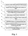
- FIG. 1 is a flow chart of an exemplary method 10 of replacing a lens in the capsular bag of an eye.
- the lens is removed from the capsular bag of the eye.
- the removed lens may be the natural crystalline lens of the eye, which has become opaque due to cataracts, or has become damaged by some other disease or injury.
- the removed lens may be an existing intraocular lens.
- the lens is removed in a surgical procedure in which the lens is broken up and vacuumed out of the eye.
- the capsular bag which supports the lens before removal, is retained in the eye, and may be used to support a replacement lens.
- the replacement lens may be an accommodating intraocular lens, which relies on forces transferred by the zonular fibers in the eye to the capsular bag. These forces can change the power and/or location of the lens by distorting and/or translating one or both of the lens surfaces.
- the distorting force exerted by the zonular fibers is limited by the finite strength of the lens capsule, fibers, and surrounding structures, and typically the intraocular lenses are designed to use this limited force to change power to cover all or part of the range of accommodation for the eye.
- the intraocular lens may be quite sensitive to compressive or expansive forces applied to its equator, and may be designed to work optimally for a particular size of capsular bag.
- the intraocular lens may experience a shift in nominal power, or a truncation of the accommodation range, which may be undesirable. Accordingly, it may be useful during a surgical procedure to measure the actual size of the capsular bag, so that an intraocular lens may be selected for implantation that corresponds to the actual size of the capsular bag.
- an angle indicator is inserted into the capsular bag. During insertion, it is often desirable to use as small an incision as possible, so the angle indicator may optionally be inserted in a folded state.
- the angle indicator is expanded.to coincide with a diameter of the capsular bag. If the angle indicator is inserted in a folded state, it may be first unfolded to reach its full size.
- the capsular bag material is flexible, so that it may be bent and reshaped. It may be relatively straightforward to position the angle indicator, which is generally ring-shaped, along the equator of the capsular bag. Typically, some gentle, back-and-forth motions applied by the surgeon are sufficient to move the angle indicator to lie along the equator of the capsular bag.
- the shape of the empty capsular bag is such that it may be well-approximated as circular when viewed from the front. Any azimuthal errors in the positioning of the angle indicator do not significantly affect the angular reading from the angle indicator, or the measured value for the capsular bag size.
- the angle indicator is read from the angle indicator.
- the angle may be formed from the intersection of two generally straight elements on the angle indicator, and may be read from a roughly central portion of the angle indicator, rather than at an edge of the angle indicator. The angle may be seen visually by the surgeon or by a camera or microscope trained on the eye.
- the angle indicator may be removed from the capsular bag of the eye.
- the angle indicator may be folded upon itself for removal, which is especially convenient if the angle indicator is inserted in the folded state.
- the angle indicator may be broken or separated into segments, and then the segment may be removed through the incision in the eye.
- the angle indicator includes cutaways on its posterior surface, which may allow sectioning in vivo for removal of the angle indicator.
- the read angle is converted to a capsular bag size.
- the size may be reported as a diameter, or, equivalently, as a circumference.
- the conversion may be done by reading values off a printed table, by reading values off a graph, by plugging the read angle into a predictive formula, by a computer, or directly by comparing the angle to a dedicated device.
- an intraocular lens may be selected.
- the lens selection may be based in part on the capsular bag size, as well as on other data, such as the required lens power.
- intraocular lenses for a given required nominal lens power, there may be several intraocular lenses available, each sized for a particular capsular bag diameter.
- the available lenses may be part of a kit, with diameter spacings of 0.5 mm, 0.25 mm, 0.2 mm, 0.15 mm, 0.1 mm, 0.05 mm, or any suitable value.
- the exact size value given from element 16 may not be exactly available in the kit, and the surgeon or practitioner may have to round off to the nearest size that is available in the kit.
- the intraocular lens may have an adapter that can attach to the circumference of the lens, which allows a single lens to be used with multiple sizes of capsular bags.
- the intraocular lens may itself be adjustable, for instance, with an adjustable haptic that can couple a particular optic to a capsular bag sized within a particular range.
- the selected lens may be surgically implanted in the capsular bag.
- element 15 follows element 14, and elements 16 and 17 follow element 14, but elements 16 and 17 need not follow element 15.
- element 15 may follow element 17, which follows element 16, which follows element 14.
- the conversion of the read angle to a capsular bag size and the selection of a lens based on the capsular bag size are essentially independent of removal of the angle indicator from the capsular bag, and these elements may be performed in any suitable order.
- FIG. 2 A schematic drawing of the angle indicator itself is shown in FIG. 2 .
- the angle indicator is shaped roughly like a broken ring, with the broken portion of the ring replaced by two segments that connect near the center of the ring.
- the ring is inserted into the capsular bag and expands until it is coincident with a diameter of the capsular bag. As the ring itself expands and contracts, the angle between the two segments increases and decreases.
- the ring may be designed so that a relatively small change in diameter produces a relatively large change in angle.
- three exemplary diameters D1, D2 and D3, are shown in FIG. 2 , along with their corresponding angles A1, A2 and A3.
- the relationship between measured angle and ring (and, therefore, capsular bag) diameter is shown in the exemplary plot in FIG. 2 . Note that the relationship need not be truly linear, as shown in FIG. 2 , but may have any suitable increasing relationship, such as a quadratic or more complex polynomial relationship.
- the practitioner inserts the angle indicator into the capsular bag, expands the angle indicator to fill the capsular bag, reads the angular value from angle indicator, and converts the read angular value to a capsular bag diameter, or equivalently, circumference.
- the angle is viewable near the center of the pupil of the lens, rather than only at the edge of the pupil or the edge of the capsular bag. This reduces the need for unusual viewing techniques, or extra handling of the pupil, and may help reduce distortion of the angle when viewed through the patient's cornea.
- angle indicator remains essentially round, for all angles/diameters within a particular range. This is accomplished by varying the radial thickness of the ring, with a maximum thickness opposite the two segments, and a minimum thickness in the regions adjacent to the joints that attach the straight segments to the rest of the ring. This is shown more clearly in FIG. 3 .
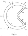
- FIG. 3 is a front-view plan drawing of an angle indicator 30.
- An incomplete annulus 31, shaped generally as an open-ended ring-shaped portion, is hingedly connected to two straight sections 32 and 33 that are hingedly connected to each other in the interior of the circle.
- the incomplete annulus 31 may optionally have a varying radial thickness around its circumference. Adjacent to the hinges 34 and 35, the radial thickness 36 may be its minimum. The radial thickness may increase farther away from the hinges 34 and 35, reaching an intermediate value 37 partially around the ring, and may finally reach a maximum value 38 directly opposite and between the hinges 34 and 35. Alternatively, the radial thickness may be constant around its circumference, or may vary In a manner other than the exemplary manner described above.
- the out-of-plane thickness is essentially constant along the incomplete annulus 31 and segments 32 and 33.
- the corners may be rounded, or may be un-rounded.
- the variation in radial thickness around the ring helps ensure that the incomplete annulus stays essentially round, even as the angle between the straight segments 32 and 33 varies.
- the diameter dimensions D1, D2 and D3 in FIG. 2 are truly diameters, and the outermost shapes of the angle indicators are essentially round at each of the three sizes shown.
- the angle indicator 30 retains its round periphery as it is compressed.
- the radial thickness of the angle indicator 30 may remain essentially constant around the ring, and the out-of-plane thickness may vary along the ring.
- both the radial thickness and the out-of-plane thickness may vary around the ring.
- the hinges 34 and 35 may be formed integrally as weakened portions of the angle indicator 30.
- the hinges 34 and 35 are formed at regions of reduced in-plane thickness at the intersections of the straight segments 32 and 33 with the incomplete annulus 31. As such, the hinges 34 and 35 may bend freely in the in-plane direction, allowing the angle indicator to freely expand and contract to attain its maximum size inside the capsular bag.
- the hinges 34 and 35 do not freely permit movement of the two segments 32 and 33 out of the plane of the angle indicator 30.
- the segments 32 and 33 are joined to each other by a third hinge 39, which is also formed as a reduction in the in-plane thickness near the hinge, also permits free in-plane movement of the segments with respect to each other and free diametric expansion and compression of the angle indicator 30, and also restricts out-of-plane movement.
- a third hinge 39 which is also formed as a reduction in the in-plane thickness near the hinge, also permits free in-plane movement of the segments with respect to each other and free diametric expansion and compression of the angle indicator 30, and also restricts out-of-plane movement.
- the segments 32 and 33 are shown in the figures as being entirely straight. In practice, there may be some curvature to all or a portion of either or both of the segments. For instance, there may be some local waviness to all or a portion of the segments 32 and 33. Alternatively, there may be a more global curvature, having a radius on the order of or larger than the angle indicator radius. In one embodiment of the angle indicator, the segments 32 and 33 are straight throughout.
- the angle indicator may measure capsular bags having a size larger than the incision through which the angle indicator is inserted.
- the angle indicator may measure capsular bag diameters on the order of 11 mm, and may fit through incisions on the order of 3 mm.
- the angle indicator may be compressed in an injector or folded upon itself during insertion (and later, during extraction), and may be unfolded and expanded for performing the measurement.
- angle indicator 30 During insertion and positioning of the angle indicator 30, it may be beneficial to gently "force open” the straight segments 32 and 33 of the angle indicator 30. This may be accomplished by applying a force on or near the rear (essentially flat) side of the hinge 39, directed outward from the ring, toward the opening between the segments.
- the force may be applied by the practitioner using the equipment that is typically used to position objects during surgery, such as a hook or forceps. Because the force may be applied directly to angle indicator 30, there may be no need for extra holes or tabs for this purpose, although holes and/or tabs may optionally be used.
- the length of the segments 32 and 33 may be varied, so that the hinge that joins them may fall on either side of the center of the ring at its nominal position. As the segment length is increased, the angle becomes easier for the practitioner to read during use, although the sensitivity is decreased. Likewise, as the segment length is decreased, the angle becomes more difficult for the practitioner to read during use, but the sensitivity is increased. In practice, the designer of ordinary skill in the art understands this trade-off, and may design an angle indicator 30 with a suitable range of operation, a suitable sensitivity, and a suitable ease of angle viewing.
- each angle indicator may be used for capsular bag diameters in the range of 9 to 10 mm, and another angle indicator may be used for the range 10 to 11 mm.
- 9 to 10 mm the range of 9 to 10 mm
- 10 to 11 mm the range of 9 to 10 mm
- the angle may be measured from roughly the center of the pupil, there is little distortion of the angle caused by the cornea. If the cornea imparts a magnification an image of the segments forming the angle, the segments themselves may appear to grow or shrink in size, but the angle between the segments remains essentially unchanged. This holds for a wide range of cornea radii, and a wide range of magnifications caused by the cornea.
- FIG. 4 shows an exemplary geometry for one embodiment of an angle indicator.
- Both the length of the incomplete annulus and the length of each straight segment may be related to a "close diameter" D 0 , which is the diameter of the angle indicator when the segments are parallel, or "closed".
- the length of the incomplete annulus is ⁇ D 0
- the length of each straight segment is qD 0 , where q is a dimensionless quantity than can between 0 and 1.
- q is 0.5
- the straight segments extend to exactly the center of the ring when the ring is "closed”.
- q 1
- the straight segments extend all the way to the opposite end of the ring when the ring is "closed”.
- the straight segments are infinitesimally small.
- the angle indicator expands to a diameter of D, with a measured angle A between the straight segments.
- Length y and angle a are mathematical constructs. We attempt to solve for A in terms of D.
- FIG. 5 is a graph of the above equation, which predicts capsular bag diameter D versus measured angle A, for several values of q.
- q is related to both sensitivity and dynamic range. For relatively short straight segments (low q), there is high sensitivity and low dynamic range. Similarly, for relatively long straight segments (high q), there is low sensitivity and high dynamic range.
- the vertex, or intersection between the straight segments is located at or near the center of the ring for at least part of the range of use.
- the circles superimposed on the various plotted curves in FIG. 5 show the operating condition at which the vertex is at the center of the ring. Note that for short segments (q ⁇ 0.5), there is no condition under which the vertex can be located in the center of the ring; these segments are just too short to extend to the center, regardless of angle A.
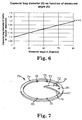
- FIG. 6 we choose a convenient set of numbers, which are merely exemplary and are not intended to be limiting in any way. For instance, if we wish to measure capsular bags having a diameter in the range of 11 mm to 13 mm, we use an angle indicator having a "closed" diameter of 10 mm and a short segment length of 6 mm, and detect angles between 30 and 90 degrees. If our detection scheme allows us to detect angle A to the nearest 15 degrees, we may measure the diameter of the capsular bag to the nearest 0.5 mm (based on the 10 mm diameter of the angle indicator). These values are merely exemplary, and any lengths and diameters may be scaled upwards or downwards. Other suitable values may also be used.
- the straight segments form an angle that is visible through the cornea.
- the angle may be viewed by eye, or may be viewed through a microscope, camera, or any suitable imaging system. Because the angle may be subject to distortion by a camera or imaging system, one angle measurement embodiment is a protractor that may be removably placed on the cornea.
- a protractor may include any instrument or device that can read an angle visually or by electronic means.
- a protractor may include a flexible sheet (e.g., a contact lens) having radial marks, a circular device having regular markings at predetermined locations along its circumference, and so forth.
- a protractor may also include software that can return a measured angle value for an angle embedded within an image.
- a protractor may include a calibrated reticle for an optical instrument, such as a microscope or a camera.
- the increments on the protractor may include one degree, five degrees, 10 degrees, 15 degrees, 20 degrees, 25 degrees, 30 degrees, 35 degrees, 40 degrees, 45 degrees, or any suitable increment.
- the protractor may be marked with indicia that correspond directly to the capsular bag size or appropriate ranges corresponding to available implant sizes.
- An exemplary protractor 70 is shown in the isometric drawing of FIG. 7 and the three views of the plan drawing of FIG. 8 .
- the protractor 70 has a generally circular ring 71 that is sized to rest on the cornea to allow measurement of the angle from the angle indicator.
- the ring 71 is small enough to fit on the eye of the patient, and large enough to surround the pupil of the eye.
- a typical range of diameters for the protractor ring may be from about 3 mm to about 12 mm, or from about 5 mm to about 8 mm.
- the straight segments 32 and 33 of the angle indicator 30 are viewable from roughly the center of the pupil, rather than requiring a measurement taken at the edge of the capsular bag.
- ring 71 of the protractor need not extend all the way to the edge of the capsular bag or to the edge of the cornea.
- the ring 71 may optionally have rounded or chamfered edges that may reduce the risk of scratching the cornea.
- the protractor 70 has a reference portion 72 that has radial edges 73 and 77.
- the reference portion 72 generally extends out of the plane of the ring 71, so that it may rest upon or extend over the cornea, which is curved.
- the intersection of radial edges 73 and 77 may fall at or near the center of the ring 71, and/or at the intersection of the straight segments 32 and 33 (e.g., at the hinge 39).
- the reference portion 72 may deform so that this intersection of radial edges 73 and 77 may lie away from the center when the protractor is not in use.
- the protractor is rigid, so that the protractor roughly maintains its shape before, during and after use.
- the reference portion 72 may extend out of the plane of the ring 71 in its relaxed state before use.
- the reference portion may 72 may be located roughly in the plane of the ring 71 before use, and may pivot in the anterior direction during use. The pivoting may occur around a weakened portion of the reference portion, which may include an optional hole or void area 81.
- the void area 81 may have a more complex shape that the hole shown in FIG. 7 , for example, to provided a weakened zone with predetermined bending characteristics or to avoid confusion that the void area 81 represents an alignment mark with the straight segments 32 and 33.
- the protractor 70 is flexible, and may be draped onto the cornea of the eye. Such a flexible protractor conforms generally to the shape of the cornea, without significantly deforming in the plane of the protractor.
- the protractor 70 may be made from a largely transparent material, and may include markings or features that indicate predetermined angle values.
- the protractor 70 may include a central feature that may be overlaid with the hinge 39 during use, and various angular features, such as reticle marks or other radial lines or features.
- the protractor may be formed on or be made integral with a contact lens that is placed onto the cornea during use.
- the protractor 70 of FIG. 7 is positioned during use so that one of the radial edges 73 and 77 lines up with one of the straight segments 32 and 33.
- the other straight segment falls elsewhere around the circumference of the ring, and may fall near one of several calibration features, such as notches, tabs, holes, extensions, annotations, colors or members.
- straight segment 33 may fall near one of feature 74, feature 75 or feature 76.
- the features may be in calibrated increments, such as 30 degrees, 20 degrees, 15 degrees, 10 degrees, or any suitable increment. For instance, if the increment is 30 degrees between each of the features 74-76, then if the straight segment 32 falls closest to the feature 74, then the angle of the indicator is closest to 30 degrees. Similarly, if the straight segment 32 falls closest to the feature 76, then the angle of the indicator is closest to 90 degrees.
- a second set of radial edge 77 and features 78-80 which may be used equally as well as the first set of radial edge 73 and features 74-76.
- the second set may be calibrated with the same angular increment as the first, or with a different angular increment as the first.
- the features may be evenly or unevenly spaced.
- the protractor 70 may be removed from the cornea of the patient.
- the protractor 70 may be removed by grasping it with the hole 81, or by an optional elevated feature or tab (not shown).
- angular measurement devices there may be other suitable angular measurement devices that may be used, as alternatives to the device shown in FIGs. 7 and 8 .
- a more conventional protractor may be used, with notches, tick marks, lines, or other visual cues extending around the circumference at a prescribed interval, such as every 30 degrees, or any other suitable interval.
- This more conventional protractor may lack the reference portion 72.
- the protractor may be made from a soft material that is draped over the cornea or rests on the facial tissue that surrounds the eye, rather than on the eye itself.
- the angle may be measured from an image formed of the eye on a screen or in software.
- the angle indicator 30 may be made integrally as a single unit, or may be made from several pieces that are assembled. The assembled pieces may be made from the same or from different materials.
- Both the angle indicator 30 and the protractor 70 may be made from any suitable biocompatible and flexible materials. For instance, either or both may be made from silicone or any polymeric material, PMMA, or any other suitable material. In one embodiment, the material or materials used may be moldable, and may not be hydrophilic. In one embodiment, the material is sterilizable by autoclave, by ETO, or by any suitable sterilization process.
- the angle indicator 30 and protractor 70 may be made from the same or from different materials.
- the angle indicator 30 and protractor 70 may be made of a tinted, opaque or fluorescing material, so that they may easily be read visually.
- the angle indicator and protractor may be supplied in pre-sterilized, sealed packages that accompany an intraocular lens. Both the angle indicator and protractor may be unsealed when needed, and disposed of once a measurement has been taken.
- each set may be used for a size range of 9 to 10 mm, and another set may be used for a size range of 10 to 11 mm.
- Each set may be color-coded so that the particular protractor is easily associated with its corresponding angle indicator, and the measured angles are easily associated with their proper measured capsular bag sizes.
- there may be other identifying characteristics for matched sets of angle indicators and protractors such as texture, etching, surface characteristics, ridges and so forth.
- the outer edges of the angle indicator may expand through viscoelastic/OVD in the capsular bag.
- the straight segments, or central arms, of the angle indicator may extend past the center of the angle indicator. These longer straight segments may fill a larger area of the pupil, and may provide an easier measurement than smaller or shorter straight segments.
- the angle indicator may be inserted into the capsular bag by an injector.
- the angle indicator may include a tether, so that the angle indicator may be more easily withdrawn after the measurement has been taken.
- the withdrawing may be done directly by the tether.
- the tether may attach the angle indicator to an injector, so that the withdrawal may be done by the via injector.
- the angle indicator may include one or more loops on the straight segments or on the incomplete annulus that extend in the anterior direction (i.e., away from the patient's eye), for positioning and removal of the angle indicator.
- the flexural characteristics of the straight segments, or arms, their bases, and/or the central hinge may be "tuned” in shape or stiffness, so that the angle indicator may stay round over a wide range of compression.
- the modulus of the angle indicator material and the width of the various angle indicator sections may be varied, so that reliable measurements may be made without excessively stretching the capsular bag.
- the angle indicators are provided in a kit, with each angle indicator having a different expansile strength.
- a kit may be used to determine the elasticity of a particular evacuated capsular bag, in order to best determine the most compatible accommodating intraocular lens.
- the angle indicators are provided in a kit, with each angle indicator having a different axial thickness.
- a kit may help match the measurement of the capsular bag size to the axial thickness of the intended implanted intraocular lens, both at the edge of the lens and centrally.
- the central linear arms, or straight segments include overlapping, curved vernier extensions.
- straight segment 32 may include one or more tangentially-curved extensions that protrudes toward segment 33
- straight segment 33 may also include one or more tangentially-curved extensions that protrudes toward segment 32, with the tangentially-curved extensions being located next to each other. In this manner, the angle may be read directly from the extensions, rather than with an additional external device such as a protractor.
- the incomplete annulus 31 may include extensions or tabs protruding from one or both of the straight segments 32, 33 and disposed along the circumference of, and in the plane of, the incomplete annulus 31. These optional extensions may help maintain the capsular circularity in the region between the straight segments 32, 33.
- the angle indicator may be used for other fields as well, such as measuring the diameters and stenosis of body cavities, especially in endoscopic and catheter-based procedures for sizing shunts and implants.
- the angle indicator allows estimation of a particular diameter, regardless of viewing magnification. This may also be used in the fields of interventional cardiology, as well as vascular, bariatric and gastroenteric surgeries.
- the angle indicator, or variations thereof may also be used to measure the size of the anterior chamber or other cavities of the eye.
Landscapes
- Health & Medical Sciences (AREA)
- Life Sciences & Earth Sciences (AREA)
- Public Health (AREA)
- Physics & Mathematics (AREA)
- Engineering & Computer Science (AREA)
- Biomedical Technology (AREA)
- Heart & Thoracic Surgery (AREA)
- General Health & Medical Sciences (AREA)
- Veterinary Medicine (AREA)
- Animal Behavior & Ethology (AREA)
- Ophthalmology & Optometry (AREA)
- Surgery (AREA)
- Oral & Maxillofacial Surgery (AREA)
- Biophysics (AREA)
- Medical Informatics (AREA)
- Molecular Biology (AREA)
- Cardiology (AREA)
- Vascular Medicine (AREA)
- Transplantation (AREA)
- Dentistry (AREA)
- Pathology (AREA)
- General Physics & Mathematics (AREA)
- Prostheses (AREA)
- Length-Measuring Instruments Using Mechanical Means (AREA)
Claims (15)
- Indicateur d'angle (30) pour mesurer la dimension du sac capsulaire d'un oeil, comprenant :un tore incomplet (31), compressible comportant une première extrémité, une seconde extrémité, une surface intérieure et une extérieure ;un premier segment (32) fixé à la première extrémité du tore incomplet et pénétrant l'intérieur du tore incomplet ; etun second segment (33) fixé à la seconde extrémité du tore incomplet,dans lequel les premier et second segments forment un certain angle, et
dans lequel le tore incomplet reste essentiellement circulaire quand il est comprimé, la surface extérieure ayant un diamètre qui varie en réaction à la compression du tore incomplet ; et
l'angle entre le premier et le second segment étant révélateur du diamètre de la surface extérieure du tore incomplet,
caractérisé en ce que le second segment est en outre fixé à l'extrémité distale du premier segment (32). - Indicateur d'angle selon la revendication 1, dans lequel le premier segment (32) est articulé en (34) sur la première extrémité du tore incomplet (31) ; et
dans lequel le second segment (33) est articulé en (35, 39) sur la seconde extrémité du tore incomplet (31) et le premier segment (32). - Indicateur d'angle selon la revendication 1 ou 2, dans lequel le premier segment (32) comprend une première partie rectiligne, et dans lequel le second segment (33) comprend une seconde partie rectiligne.
- Indicateur d'angle selon la revendication 1, 2 ou 3, dans lequel le tore incomplet (31) présente une épaisseur radiale qui varie le long de sa longueur, l'épaisseur radiale au milieu (38) équidistant des première et seconde extrémités étant supérieure à celle aux deux extrémités (36), première et seconde.
- Indicateur d'angle selon l'une quelconque des revendications précédentes, dans lequel l'angle formé par les premier et second segments est aigu.
- Indicateur d'angle selon l'une quelconque des revendications précédentes, dans lequel le tore incomplet et les premier et second segments sont formés d'une seule pièce.
- Indicateur d'angle selon l'une quelconque des revendications précédentes, dans lequel le tore incomplet (31) et les premier et second segments (32, 33) sont joints par des charnières (34, 35), chaque charnière comprenant une réduction d'épaisseur dans le plan.
- Indicateur d'angle selon l'une quelconque des revendications précédentes, dans lequel les premier et second segments (32, 33) ont des longueurs qui sont supérieures à la moitié du diamètre du tore incomplet et inférieures au diamètre du tore incomplet et/ou qui sont égales l'une à l'autre.
- Indicateur d'angle selon l'une quelconque des revendications précédentes, dans lequel le tore incomplet et les premier et second segments ont des bords arrondis.
- Combinaison de l'indicateur d'angle selon l'une quelconque des revendications précédentes et
d'un rapporteur d'angle (70) qui peut être disposé en face de l'indicateur d'angle (30) pour mesurer l'angle formé par les segments (32, 33), le rapporteur comprenant :un repère d'alignement (72) à disposer en face de l'intersection des segments de l'indicateur d'angle et au moins un bord radial (73, 77) de référence disposé le long de l'un des segments ; etune pluralité d'éléments (74 à 80) disposés avec précision, situés à des emplacements angulaires prédéterminés à partir dudit bord radial (73, 77) de référence. - Combinaison selon la revendication 10, dans laquelle les éléments (74 à 80) du rapporteur (70) sont des protubérances et/ou des encoches et/ou des trous et comportent un code couleur et/ou un symbole alphanumérique.
- Combinaison selon la revendication 10 ou 11, dans laquelle les emplacements angulaires prédéterminés du rapporteur sont équidistants.
- Combinaison selon l'une quelconque des revendications 10 à 12, dans laquelle le rapporteur est flexible et est configuré pour être étendu sur la cornée de l'oeil.
- Combinaison selon l'une quelconque des revendications 10 à 13, dans laquelle le rapporteur comprend une partie annulaire (71) et une partie de référence (72) disposé à l'intérieur de la partie annulaire (71), la partie de référence (72) comportant le bord radial (73, 77) de référence, les éléments (74 à 80) étant disposé le long de la partie annulaire (71).
- Combinaison selon la revendication 14, dans laquelle la partie de référence (72) s'éloigne vers l'avant de la partie annulaire (71).
Applications Claiming Priority (2)
| Application Number | Priority Date | Filing Date | Title |
|---|---|---|---|
| US11/739,392 US7993398B2 (en) | 2007-04-24 | 2007-04-24 | Angle indicator for capsular bag size measurement |
| PCT/US2008/061180 WO2008134322A1 (fr) | 2007-04-24 | 2008-04-22 | Indicateur d'angle pour la mesure des dimensions d'un sac capsulaire |
Publications (2)
| Publication Number | Publication Date |
|---|---|
| EP2139379A1 EP2139379A1 (fr) | 2010-01-06 |
| EP2139379B1 true EP2139379B1 (fr) | 2016-06-22 |
Family
ID=41280279
Family Applications (1)
| Application Number | Title | Priority Date | Filing Date |
|---|---|---|---|
| EP08746574.6A Not-in-force EP2139379B1 (fr) | 2007-04-24 | 2008-04-22 | Indicateur d'angle pour la mesure des dimensions d'un sac capsulaire |
Country Status (5)
| Country | Link |
|---|---|
| US (1) | US7993398B2 (fr) |
| EP (1) | EP2139379B1 (fr) |
| AU (1) | AU2008245833B2 (fr) |
| CA (1) | CA2685203C (fr) |
| WO (1) | WO2008134322A1 (fr) |
Families Citing this family (27)
| Publication number | Priority date | Publication date | Assignee | Title |
|---|---|---|---|---|
| US7303582B2 (en) * | 2003-03-21 | 2007-12-04 | Advanced Medical Optics, Inc. | Foldable angle-fixated intraocular lens |
| US7993398B2 (en) | 2007-04-24 | 2011-08-09 | Abbott Medical Optics Inc. | Angle indicator for capsular bag size measurement |
| US9216080B2 (en) | 2007-08-27 | 2015-12-22 | Amo Groningen B.V. | Toric lens with decreased sensitivity to cylinder power and rotation and method of using the same |
| US8974526B2 (en) * | 2007-08-27 | 2015-03-10 | Amo Groningen B.V. | Multizonal lens with extended depth of focus |
| EP2243052B1 (fr) | 2008-02-15 | 2011-09-07 | AMO Regional Holdings | Système, verre ophtalmique et procédé pour étendre la profondeur de foyer |
| US8439498B2 (en) | 2008-02-21 | 2013-05-14 | Abbott Medical Optics Inc. | Toric intraocular lens with modified power characteristics |
| EP2268191B1 (fr) * | 2008-03-28 | 2013-03-20 | Abbott Medical Optics Inc. | Systèmes de mesure oculaire |
| US8862447B2 (en) | 2010-04-30 | 2014-10-14 | Amo Groningen B.V. | Apparatus, system and method for predictive modeling to design, evaluate and optimize ophthalmic lenses |
| EP2322123A1 (fr) | 2009-11-13 | 2011-05-18 | Carl Zeiss Surgical GmbH | Dispositif chirurgical |
| WO2011075668A1 (fr) | 2009-12-18 | 2011-06-23 | Abbott Medical Optics Inc. | Lentille ophtalmique, systèmes et procédés dotés d'un retard de phase variable et angulaire |
| DE102010010554A1 (de) * | 2010-03-05 | 2011-09-08 | Geuder Ag | Vorrichtung zum Vermessen des Kapselsacks eines Auges |
| US9220590B2 (en) | 2010-06-10 | 2015-12-29 | Z Lens, Llc | Accommodative intraocular lens and method of improving accommodation |
| WO2012073112A1 (fr) | 2010-12-01 | 2012-06-07 | Amo Groningen B.V. | Verre progressif possédant une progression de puissance d'addition optique, et système et procédé l'utilisant |
| US9364318B2 (en) | 2012-05-10 | 2016-06-14 | Z Lens, Llc | Accommodative-disaccommodative intraocular lens |
| CA2877203A1 (fr) | 2012-12-04 | 2014-06-12 | Amo Groningen B.V. | Lentilles, systemes et procedes pour fournir des traitements personnalises binoculaires pour corriger une presbytie |
| US10117572B2 (en) * | 2013-04-26 | 2018-11-06 | Carl Zeiss Meditec Ag | Method, ophthalmic measuring system and computer-readable storage medium for selecting an intraocular lens |
| CA3013858A1 (fr) | 2016-02-09 | 2017-08-17 | Amo Groningen B.V. | Lentille intraoculaire progressive et ses procedes d'utilisation et de fabrication |
| WO2017165679A1 (fr) | 2016-03-23 | 2017-09-28 | Abbott Medical Optics Inc. | Appareil ophtalmique à méridiens correctifs comportant une bande de tolérance étendue dotée de surfaces réfractives de forme libre |
| EP3932368B1 (fr) | 2016-03-23 | 2025-02-26 | Johnson & Johnson Surgical Vision, Inc. | Appareil ophtalmique à méridiens correctifs présentant une bande de tolérance étendue |
| CN109890325B (zh) | 2016-08-24 | 2021-10-26 | Z晶状体有限责任公司 | 双模式调节-去调节型人工晶状体 |
| AU2017352030B2 (en) | 2016-10-25 | 2023-03-23 | Amo Groningen B.V. | Realistic eye models to design and evaluate intraocular lenses for a large field of view |
| US10739227B2 (en) | 2017-03-23 | 2020-08-11 | Johnson & Johnson Surgical Vision, Inc. | Methods and systems for measuring image quality |
| CA3082053A1 (fr) | 2017-11-30 | 2019-06-06 | Amo Groningen B.V. | Lentilles intraoculaires permettant d'ameliorer l'independance vis a vis des lunettes apres une intervention chirurgicale et leurs procedes de fabrication |
| US11886046B2 (en) | 2019-12-30 | 2024-01-30 | Amo Groningen B.V. | Multi-region refractive lenses for vision treatment |
| US12239529B2 (en) | 2021-03-09 | 2025-03-04 | Amo Groningen B.V. | Refractive extended depth of focus intraocular lens, and methods of use and manufacture |
| EP4333685B1 (fr) | 2021-05-05 | 2026-01-14 | AMO Groningen B.V. | Système d'halomètre annulaire et procédé de quantification de dysphotopsies |
| CN114027883B (zh) * | 2021-11-08 | 2023-06-23 | 中山大学中山眼科中心 | 一种晶状体生物参数的测量方法、装置及系统 |
Family Cites Families (84)
| Publication number | Priority date | Publication date | Assignee | Title |
|---|---|---|---|---|
| US4093361A (en) | 1971-11-15 | 1978-06-06 | Precision Cosmet Co., Inc. | Composite prosthetic polymeric devices |
| US4077071A (en) | 1976-03-15 | 1978-03-07 | Freeman Jerre M | Neutral buoyancy intraocular lens device |
| US4134160A (en) | 1977-03-16 | 1979-01-16 | Bayers Jon Herbert | Intraocular lens |
| US4174543A (en) | 1978-06-01 | 1979-11-20 | Kelman Charles D | Intraocular lenses |
| US4254509A (en) | 1979-04-09 | 1981-03-10 | Tennant Jerald L | Accommodating intraocular implant |
| US4254510A (en) | 1979-06-18 | 1981-03-10 | Tennant Jerald L | Implant lens with biarcuate fixation |
| US4316293A (en) | 1979-08-27 | 1982-02-23 | Bayers Jon Herbert | Flexible intraocular lens |
| US4319564A (en) | 1980-01-03 | 1982-03-16 | Karickhoff John R | Instrument for measurement of the diameter of the anterior chamber of the eye |
| US4249272A (en) | 1980-03-05 | 1981-02-10 | Stanley Poler | Intraocular lens |
| USRE32525F1 (en) | 1980-04-01 | 1989-05-09 | Universal intraocular lens and a method of measuring an eye chamber size | |
| US4377873A (en) | 1980-10-30 | 1983-03-29 | Reichert Jr Henry L | Intraocular lens |
| US4480340A (en) | 1981-02-18 | 1984-11-06 | Shepard Dennis D | Intraocular lens with resilient support means |
| DE8107675U1 (de) | 1981-03-03 | 1981-07-30 | Porsche Design Produkte Vertriebsgesellschaft mbH, 5020 Salzburg | "geodreieck" |
| US4370760A (en) | 1981-03-25 | 1983-02-01 | Kelman Charles D | Anterior chamber intraocular lens |
| DE3119002A1 (de) | 1981-05-13 | 1982-12-02 | INPROHOLD Establishment, 9490 Vaduz | Hinterkammer-implantationslinse |
| US4403353A (en) | 1981-06-25 | 1983-09-13 | Tennant Jerald L | Anterior chamber implant lens |
| US4446581A (en) | 1981-09-02 | 1984-05-08 | Blake L W | Intraocular lens with free-ended sizing prong |
| US4404694A (en) | 1982-03-18 | 1983-09-20 | Kelman Charles D | Intraocular lens |
| DE3431224A1 (de) | 1983-08-04 | 1986-03-06 | Steven B Siepser | Kuenstliche intraokulare linse |
| US4556998A (en) | 1983-08-04 | 1985-12-10 | Siepser Steven B | Artificial intraocular lenses and method for their surgical implantation |
| US4551864A (en) | 1983-08-18 | 1985-11-12 | Iolab Corporation | Anterior chamber lens |
| US4560383A (en) | 1983-10-27 | 1985-12-24 | Leiske Larry G | Anterior chamber intraocular lens |
| US4687484A (en) | 1983-12-12 | 1987-08-18 | Kaplan Linda J | Anterior chamber intraocular lens |
| US4605409A (en) | 1984-05-21 | 1986-08-12 | Kelman Charles D | Intraocular lens with miniature optic having expandable and contractible glare-reducing means |
| US4629460A (en) | 1984-06-25 | 1986-12-16 | Dyer Robert L | Intraocular lens |
| US4787904A (en) | 1984-07-06 | 1988-11-29 | Severin Sanford L | Hydrophillic intraocular lens |
| US4629462A (en) | 1984-07-13 | 1986-12-16 | Feaster Fred T | Intraocular lens with coiled haptics |
| SU1311063A1 (ru) | 1984-09-27 | 1988-01-30 | Московский научно-исследовательский институт микрохирургии глаза | Искусственный хрусталик глаза |
| US4781717A (en) | 1985-07-24 | 1988-11-01 | Grendahl Dennis T | Intraocular lens |
| US4676791A (en) | 1985-08-01 | 1987-06-30 | Surgidev Corporation | Intraocular lens and method for making same |
| US4687485A (en) | 1985-08-23 | 1987-08-18 | Barnes-Hind, Inc. | Intraocular lens with leg means having compressible regions and/or color |
| US4681102A (en) | 1985-09-11 | 1987-07-21 | Bartell Michael T | Apparatus and method for insertion of an intra-ocular lens |
| US4725277A (en) | 1986-05-14 | 1988-02-16 | Precision-Cosmet Co., Inc. | Intraocular lens with tapered haptics |
| US4676792A (en) | 1986-08-26 | 1987-06-30 | Donald Praeger | Method and artificial intraocular lens device for the phakic treatment of myopia |
| US5225858A (en) | 1987-06-01 | 1993-07-06 | Valdemar Portney | Multifocal ophthalmic lens |
| US4834748A (en) | 1987-09-29 | 1989-05-30 | Allergan, Inc. | Method and apparatus for removing corneal tissue |
| US4863539A (en) | 1987-11-06 | 1989-09-05 | Optical Radiation Corporation | Haptic attachment for intraocular lenses |
| US5047052A (en) | 1987-11-06 | 1991-09-10 | Seymour Dubroff | Anterior chamber intraocular lens with four point fixation |
| FR2631228B1 (fr) | 1988-05-11 | 1990-08-10 | Domilens Laboratoires | Implant intra-oculaire de chambre anterieure |
| US4997442A (en) | 1989-05-04 | 1991-03-05 | Alcon Laboratories, Inc. | Bicomposite intraocular lenses |
| US5078742A (en) | 1989-08-28 | 1992-01-07 | Elie Dahan | Posterior chamber lens implant |
| US5019097A (en) | 1989-11-22 | 1991-05-28 | Allergan, Inc. | Corneal onlay lenses and methods for attaching same |
| US5147397A (en) | 1990-07-03 | 1992-09-15 | Allergan, Inc. | Intraocular lens and method for making same |
| US5258025A (en) | 1990-11-21 | 1993-11-02 | Fedorov Svjatoslav N | Corrective intraocular lens |
| US5217491A (en) | 1990-12-27 | 1993-06-08 | American Cyanamid Company | Composite intraocular lens |
| US5133749A (en) | 1991-05-13 | 1992-07-28 | Nordan Lee T | Centrating haptics |
| US5147395A (en) | 1991-07-16 | 1992-09-15 | Allergan Inc. | Small incision endocapsulator IOL |
| US5203790A (en) | 1991-11-12 | 1993-04-20 | Henry H. McDonald | Foldable plastic optical lens with reduced thickness light blocking segments, and anchoring means |
| US5476513A (en) | 1992-02-28 | 1995-12-19 | Allergan, Inc. | Intraocular lens |
| US5201763A (en) | 1992-02-28 | 1993-04-13 | Allergan, Inc. | Thin intraocular lens |
| US5197981A (en) | 1992-04-23 | 1993-03-30 | Alcon Surgical, Inc. | Intraocular lens having haptic of specific curvature and proportion |
| US5433745A (en) | 1993-10-13 | 1995-07-18 | Allergan, Inc. | Corneal implants and methods for producing same |
| JP3745394B2 (ja) | 1994-07-04 | 2006-02-15 | 武敏 鈴木 | 眼内レンズ |
| JPH08196507A (ja) | 1995-01-23 | 1996-08-06 | Nikon Corp | 眼科装置 |
| US5801807A (en) | 1995-08-08 | 1998-09-01 | Nikon Corporation | Ophthalmic illumination device having adjustable transmittance member and microscope for operation using the same |
| WO1997012564A1 (fr) | 1995-10-06 | 1997-04-10 | Cumming J Stuart | Lentilles intraoculaires a haptiques fixes |
| US5716403A (en) | 1995-12-06 | 1998-02-10 | Alcon Laboratories, Inc. | Single piece foldable intraocular lens |
| FR2745711B1 (fr) | 1996-03-05 | 1998-05-07 | Ioltechnologie Production | Implant souple formant lentille intraoculaire de chambre posterieure |
| FR2748200B1 (fr) | 1996-05-03 | 1998-09-25 | W K Et Associes | Implant intraoculaire monobloc souple |
| US6015435A (en) | 1996-10-24 | 2000-01-18 | International Vision, Inc. | Self-centering phakic intraocular lens |
| DE19724108C1 (de) | 1997-06-09 | 1998-11-19 | Morcher Gmbh | Kapseläquatorring |
| US5928282A (en) | 1997-06-13 | 1999-07-27 | Bausch & Lomb Surgical, Inc. | Intraocular lens |
| US6129759A (en) | 1997-12-10 | 2000-10-10 | Staar Surgical Company, Inc. | Frosted haptic intraocular lens |
| SE510945C2 (sv) | 1998-05-13 | 1999-07-12 | Tormek Ab | Vinkelmätare vid slipning av eggverktyg |
| US6235055B1 (en) | 1999-08-09 | 2001-05-22 | Milton W. Chu | Intraocular lens having colored haptics for anterior/posterior orientation, and method for implanting it |
| US6261321B1 (en) | 1999-09-01 | 2001-07-17 | Robert E. Kellan | Phakic or aphakic intraocular lens assembly |
| FR2801192B1 (fr) | 1999-11-19 | 2002-08-09 | Corneal Ind | Anneau pour sac capsulaire et ensemble constitue par un tel anneau et son injecteur |
| US20010051825A1 (en) | 1999-12-27 | 2001-12-13 | Peterson Norman D. | Temporary lenses and method for providing correct lens power |
| DE10002672C2 (de) | 2000-01-24 | 2002-01-03 | Bioshape Ag | Vorrichtung und Verfahren zur Bestimmung des Radius oder des Durchmesssers des Kammerwinkels eines Auges |
| US7455407B2 (en) | 2000-02-11 | 2008-11-25 | Amo Wavefront Sciences, Llc | System and method of measuring and mapping three dimensional structures |
| US6598606B2 (en) | 2000-05-24 | 2003-07-29 | Pharmacia Groningen Bv | Methods of implanting an intraocular lens |
| US20050251254A1 (en) | 2000-06-02 | 2005-11-10 | Brady Daniel G | Method of implanting accommodating intraocular lenses |
| US6419697B1 (en) | 2000-07-07 | 2002-07-16 | Charles David Kelman | Clip-on optic assembly |
| AU2002240147A1 (en) | 2001-02-01 | 2002-08-12 | Tekia, Inc. | Two part "l"- or "s"-shaped phakic iol |
| US20040167622A1 (en) | 2001-03-26 | 2004-08-26 | Sunalp Murad A. | Temporary refractive intraocular lens and methods of use |
| US7130835B2 (en) | 2002-03-28 | 2006-10-31 | Bausch & Lomb Incorporated | System and method for predictive ophthalmic correction |
| US20040068317A1 (en) | 2002-10-07 | 2004-04-08 | Knight Patricia M. | Anterior chamber intraocular lens with size and position indicators |
| US7303582B2 (en) | 2003-03-21 | 2007-12-04 | Advanced Medical Optics, Inc. | Foldable angle-fixated intraocular lens |
| DE10344781A1 (de) | 2003-09-23 | 2005-04-14 | Carl Zeiss Meditec Ag | Verfahren zur Bestimmung einer Intraokularlinse |
| DE102004046577A1 (de) | 2004-09-23 | 2006-04-06 | Geuder Ag | Vorrichtung zum Vermessen der Vorderkammer eines Auges |
| US7623251B2 (en) | 2006-04-07 | 2009-11-24 | Amo Wavefront Sciences, Llc. | Geometric measurement system and method of measuring a geometric characteristic of an object |
| US7879089B2 (en) | 2006-05-17 | 2011-02-01 | Alcon, Inc. | Correction of higher order aberrations in intraocular lenses |
| US7993398B2 (en) | 2007-04-24 | 2011-08-09 | Abbott Medical Optics Inc. | Angle indicator for capsular bag size measurement |
| EP2268191B1 (fr) | 2008-03-28 | 2013-03-20 | Abbott Medical Optics Inc. | Systèmes de mesure oculaire |
-
2007
- 2007-04-24 US US11/739,392 patent/US7993398B2/en not_active Expired - Fee Related
-
2008
- 2008-04-22 EP EP08746574.6A patent/EP2139379B1/fr not_active Not-in-force
- 2008-04-22 AU AU2008245833A patent/AU2008245833B2/en not_active Ceased
- 2008-04-22 WO PCT/US2008/061180 patent/WO2008134322A1/fr not_active Ceased
- 2008-04-22 CA CA2685203A patent/CA2685203C/fr active Active
Non-Patent Citations (1)
| Title |
|---|
| None * |
Also Published As
| Publication number | Publication date |
|---|---|
| US7993398B2 (en) | 2011-08-09 |
| CA2685203C (fr) | 2017-09-12 |
| AU2008245833A1 (en) | 2008-11-06 |
| WO2008134322A1 (fr) | 2008-11-06 |
| AU2008245833B2 (en) | 2013-08-15 |
| US20080269642A1 (en) | 2008-10-30 |
| EP2139379A1 (fr) | 2010-01-06 |
| CA2685203A1 (fr) | 2008-11-06 |
Similar Documents
| Publication | Publication Date | Title |
|---|---|---|
| EP2139379B1 (fr) | Indicateur d'angle pour la mesure des dimensions d'un sac capsulaire | |
| US8241353B2 (en) | Angle indicator for ocular measurements | |
| US5171248A (en) | Medullary caliper | |
| CN102014793B (zh) | 非球面复曲面眼内透镜 | |
| JP2010057931A (ja) | 調節式眼内レンズアッセンブリと、調節能力測定インプラント | |
| RU2232561C2 (ru) | Внутриглазной хрусталик, имеющий конструкцию для регулирования его осевого смещения после имплантации | |
| US20050107873A1 (en) | Accommodative intraocular lens and method of implantation | |
| EP0297115A1 (fr) | Lentille intraoculaire a incision reduite et a puissance ajustable | |
| US20010051825A1 (en) | Temporary lenses and method for providing correct lens power | |
| EP3531973A1 (fr) | Lentille intraoculaire d'accommodation et procédés d'implantation | |
| JPH0470018B2 (fr) | ||
| US20140107459A1 (en) | Devices, systems, and methods for intraocular measurements | |
| EP3247312A1 (fr) | Dispositif de calibrage de valve prothétique et ensemble comprenant celui-ci | |
| EP2552351B1 (fr) | Lentille intra-oculaire | |
| WO2025034817A1 (fr) | Dispositifs, systèmes et procédés d'évaluation objective de l'accommodation de lentilles intraoculaires | |
| CA2719935A1 (fr) | Systemes de mesure oculaire | |
| CN108472050A (zh) | 用于检测中空部件的变形的装置 | |
| EP2078507A1 (fr) | Petit crochet de sonde pour arthroscopie | |
| Fleming | Radial keratotomy and corneal topography | |
| HK1175391B (en) | Intraocular lens |
Legal Events
| Date | Code | Title | Description |
|---|---|---|---|
| PUAI | Public reference made under article 153(3) epc to a published international application that has entered the european phase |
Free format text: ORIGINAL CODE: 0009012 |
|
| 17P | Request for examination filed |
Effective date: 20091020 |
|
| AK | Designated contracting states |
Kind code of ref document: A1 Designated state(s): AT BE BG CH CY CZ DE DK EE ES FI FR GB GR HR HU IE IS IT LI LT LU LV MC MT NL NO PL PT RO SE SI SK TR |
|
| RAP1 | Party data changed (applicant data changed or rights of an application transferred) |
Owner name: ABBOTT MEDICAL OPTICS INC. |
|
| DAX | Request for extension of the european patent (deleted) | ||
| 17Q | First examination report despatched |
Effective date: 20110419 |
|
| GRAP | Despatch of communication of intention to grant a patent |
Free format text: ORIGINAL CODE: EPIDOSNIGR1 |
|
| INTG | Intention to grant announced |
Effective date: 20160208 |
|
| GRAS | Grant fee paid |
Free format text: ORIGINAL CODE: EPIDOSNIGR3 |
|
| GRAA | (expected) grant |
Free format text: ORIGINAL CODE: 0009210 |
|
| AK | Designated contracting states |
Kind code of ref document: B1 Designated state(s): AT BE BG CH CY CZ DE DK EE ES FI FR GB GR HR HU IE IS IT LI LT LU LV MC MT NL NO PL PT RO SE SI SK TR |
|
| REG | Reference to a national code |
Ref country code: GB Ref legal event code: FG4D |
|
| REG | Reference to a national code |
Ref country code: CH Ref legal event code: EP |
|
| REG | Reference to a national code |
Ref country code: IE Ref legal event code: FG4D |
|
| REG | Reference to a national code |
Ref country code: AT Ref legal event code: REF Ref document number: 807163 Country of ref document: AT Kind code of ref document: T Effective date: 20160715 |
|
| REG | Reference to a national code |
Ref country code: DE Ref legal event code: R096 Ref document number: 602008044789 Country of ref document: DE |
|
| REG | Reference to a national code |
Ref country code: NL Ref legal event code: FP |
|
| REG | Reference to a national code |
Ref country code: LT Ref legal event code: MG4D |
|
| PG25 | Lapsed in a contracting state [announced via postgrant information from national office to epo] |
Ref country code: NO Free format text: LAPSE BECAUSE OF FAILURE TO SUBMIT A TRANSLATION OF THE DESCRIPTION OR TO PAY THE FEE WITHIN THE PRESCRIBED TIME-LIMIT Effective date: 20160922 Ref country code: LT Free format text: LAPSE BECAUSE OF FAILURE TO SUBMIT A TRANSLATION OF THE DESCRIPTION OR TO PAY THE FEE WITHIN THE PRESCRIBED TIME-LIMIT Effective date: 20160622 Ref country code: FI Free format text: LAPSE BECAUSE OF FAILURE TO SUBMIT A TRANSLATION OF THE DESCRIPTION OR TO PAY THE FEE WITHIN THE PRESCRIBED TIME-LIMIT Effective date: 20160622 |
|
| REG | Reference to a national code |
Ref country code: AT Ref legal event code: MK05 Ref document number: 807163 Country of ref document: AT Kind code of ref document: T Effective date: 20160622 |
|
| PG25 | Lapsed in a contracting state [announced via postgrant information from national office to epo] |
Ref country code: GR Free format text: LAPSE BECAUSE OF FAILURE TO SUBMIT A TRANSLATION OF THE DESCRIPTION OR TO PAY THE FEE WITHIN THE PRESCRIBED TIME-LIMIT Effective date: 20160923 Ref country code: LV Free format text: LAPSE BECAUSE OF FAILURE TO SUBMIT A TRANSLATION OF THE DESCRIPTION OR TO PAY THE FEE WITHIN THE PRESCRIBED TIME-LIMIT Effective date: 20160622 Ref country code: HR Free format text: LAPSE BECAUSE OF FAILURE TO SUBMIT A TRANSLATION OF THE DESCRIPTION OR TO PAY THE FEE WITHIN THE PRESCRIBED TIME-LIMIT Effective date: 20160622 Ref country code: SE Free format text: LAPSE BECAUSE OF FAILURE TO SUBMIT A TRANSLATION OF THE DESCRIPTION OR TO PAY THE FEE WITHIN THE PRESCRIBED TIME-LIMIT Effective date: 20160622 |
|
| PG25 | Lapsed in a contracting state [announced via postgrant information from national office to epo] |
Ref country code: EE Free format text: LAPSE BECAUSE OF FAILURE TO SUBMIT A TRANSLATION OF THE DESCRIPTION OR TO PAY THE FEE WITHIN THE PRESCRIBED TIME-LIMIT Effective date: 20160622 Ref country code: IS Free format text: LAPSE BECAUSE OF FAILURE TO SUBMIT A TRANSLATION OF THE DESCRIPTION OR TO PAY THE FEE WITHIN THE PRESCRIBED TIME-LIMIT Effective date: 20161022 Ref country code: CZ Free format text: LAPSE BECAUSE OF FAILURE TO SUBMIT A TRANSLATION OF THE DESCRIPTION OR TO PAY THE FEE WITHIN THE PRESCRIBED TIME-LIMIT Effective date: 20160622 Ref country code: SK Free format text: LAPSE BECAUSE OF FAILURE TO SUBMIT A TRANSLATION OF THE DESCRIPTION OR TO PAY THE FEE WITHIN THE PRESCRIBED TIME-LIMIT Effective date: 20160622 Ref country code: RO Free format text: LAPSE BECAUSE OF FAILURE TO SUBMIT A TRANSLATION OF THE DESCRIPTION OR TO PAY THE FEE WITHIN THE PRESCRIBED TIME-LIMIT Effective date: 20160622 Ref country code: IT Free format text: LAPSE BECAUSE OF FAILURE TO SUBMIT A TRANSLATION OF THE DESCRIPTION OR TO PAY THE FEE WITHIN THE PRESCRIBED TIME-LIMIT Effective date: 20160622 |
|
| PG25 | Lapsed in a contracting state [announced via postgrant information from national office to epo] |
Ref country code: PT Free format text: LAPSE BECAUSE OF FAILURE TO SUBMIT A TRANSLATION OF THE DESCRIPTION OR TO PAY THE FEE WITHIN THE PRESCRIBED TIME-LIMIT Effective date: 20161024 Ref country code: PL Free format text: LAPSE BECAUSE OF FAILURE TO SUBMIT A TRANSLATION OF THE DESCRIPTION OR TO PAY THE FEE WITHIN THE PRESCRIBED TIME-LIMIT Effective date: 20160622 Ref country code: AT Free format text: LAPSE BECAUSE OF FAILURE TO SUBMIT A TRANSLATION OF THE DESCRIPTION OR TO PAY THE FEE WITHIN THE PRESCRIBED TIME-LIMIT Effective date: 20160622 Ref country code: BE Free format text: LAPSE BECAUSE OF FAILURE TO SUBMIT A TRANSLATION OF THE DESCRIPTION OR TO PAY THE FEE WITHIN THE PRESCRIBED TIME-LIMIT Effective date: 20160622 Ref country code: ES Free format text: LAPSE BECAUSE OF FAILURE TO SUBMIT A TRANSLATION OF THE DESCRIPTION OR TO PAY THE FEE WITHIN THE PRESCRIBED TIME-LIMIT Effective date: 20160622 |
|
| REG | Reference to a national code |
Ref country code: FR Ref legal event code: PLFP Year of fee payment: 10 |
|
| REG | Reference to a national code |
Ref country code: DE Ref legal event code: R097 Ref document number: 602008044789 Country of ref document: DE |
|
| PLBE | No opposition filed within time limit |
Free format text: ORIGINAL CODE: 0009261 |
|
| STAA | Information on the status of an ep patent application or granted ep patent |
Free format text: STATUS: NO OPPOSITION FILED WITHIN TIME LIMIT |
|
| 26N | No opposition filed |
Effective date: 20170323 |
|
| PG25 | Lapsed in a contracting state [announced via postgrant information from national office to epo] |
Ref country code: DK Free format text: LAPSE BECAUSE OF FAILURE TO SUBMIT A TRANSLATION OF THE DESCRIPTION OR TO PAY THE FEE WITHIN THE PRESCRIBED TIME-LIMIT Effective date: 20160622 |
|
| PG25 | Lapsed in a contracting state [announced via postgrant information from national office to epo] |
Ref country code: SI Free format text: LAPSE BECAUSE OF FAILURE TO SUBMIT A TRANSLATION OF THE DESCRIPTION OR TO PAY THE FEE WITHIN THE PRESCRIBED TIME-LIMIT Effective date: 20160622 |
|
| REG | Reference to a national code |
Ref country code: IE Ref legal event code: MM4A |
|
| PG25 | Lapsed in a contracting state [announced via postgrant information from national office to epo] |
Ref country code: MC Free format text: LAPSE BECAUSE OF FAILURE TO SUBMIT A TRANSLATION OF THE DESCRIPTION OR TO PAY THE FEE WITHIN THE PRESCRIBED TIME-LIMIT Effective date: 20160622 |
|
| REG | Reference to a national code |
Ref country code: CH Ref legal event code: NV Representative=s name: E. BLUM AND CO. AG PATENT- UND MARKENANWAELTE , CH |
|
| PG25 | Lapsed in a contracting state [announced via postgrant information from national office to epo] |
Ref country code: LU Free format text: LAPSE BECAUSE OF NON-PAYMENT OF DUE FEES Effective date: 20170422 |
|
| REG | Reference to a national code |
Ref country code: FR Ref legal event code: PLFP Year of fee payment: 11 |
|
| PG25 | Lapsed in a contracting state [announced via postgrant information from national office to epo] |
Ref country code: IE Free format text: LAPSE BECAUSE OF NON-PAYMENT OF DUE FEES Effective date: 20170422 |
|
| PG25 | Lapsed in a contracting state [announced via postgrant information from national office to epo] |
Ref country code: MT Free format text: LAPSE BECAUSE OF NON-PAYMENT OF DUE FEES Effective date: 20170422 |
|
| REG | Reference to a national code |
Ref country code: CH Ref legal event code: PFA Owner name: JOHNSON AND JOHNSON SURGICAL VISION, INC., US Free format text: FORMER OWNER: ABBOTT MEDICAL OPTICS INC., US |
|
| REG | Reference to a national code |
Ref country code: DE Ref legal event code: R081 Ref document number: 602008044789 Country of ref document: DE Owner name: JOHNSON & JOHNSON SURGICAL VISION, INC., IRVIN, US Free format text: FORMER OWNER: ABBOTT MEDICAL OPTICS INC., SANTA ANA, CALIF., US Ref country code: DE Ref legal event code: R081 Ref document number: 602008044789 Country of ref document: DE Owner name: JOHNSON & JOHNSON SURGICAL VISION, INC. (N. D., US Free format text: FORMER OWNER: ABBOTT MEDICAL OPTICS INC., SANTA ANA, CALIF., US |
|
| REG | Reference to a national code |
Ref country code: NL Ref legal event code: HC Owner name: JOHNSON & JOHNSON SURGICAL VISION, INC.; US Free format text: DETAILS ASSIGNMENT: CHANGE OF OWNER(S), CHANGE OF OWNER(S) NAME; FORMER OWNER NAME: ABBOTT MEDICAL OPTICS INC. Effective date: 20181204 |
|
| PG25 | Lapsed in a contracting state [announced via postgrant information from national office to epo] |
Ref country code: HU Free format text: LAPSE BECAUSE OF FAILURE TO SUBMIT A TRANSLATION OF THE DESCRIPTION OR TO PAY THE FEE WITHIN THE PRESCRIBED TIME-LIMIT; INVALID AB INITIO Effective date: 20080422 |
|
| PG25 | Lapsed in a contracting state [announced via postgrant information from national office to epo] |
Ref country code: BG Free format text: LAPSE BECAUSE OF FAILURE TO SUBMIT A TRANSLATION OF THE DESCRIPTION OR TO PAY THE FEE WITHIN THE PRESCRIBED TIME-LIMIT Effective date: 20160622 |
|
| PG25 | Lapsed in a contracting state [announced via postgrant information from national office to epo] |
Ref country code: CY Free format text: LAPSE BECAUSE OF NON-PAYMENT OF DUE FEES Effective date: 20160622 |
|
| PG25 | Lapsed in a contracting state [announced via postgrant information from national office to epo] |
Ref country code: TR Free format text: LAPSE BECAUSE OF FAILURE TO SUBMIT A TRANSLATION OF THE DESCRIPTION OR TO PAY THE FEE WITHIN THE PRESCRIBED TIME-LIMIT Effective date: 20160622 |
|
| PGFP | Annual fee paid to national office [announced via postgrant information from national office to epo] |
Ref country code: GB Payment date: 20220303 Year of fee payment: 15 Ref country code: CH Payment date: 20220314 Year of fee payment: 15 |
|
| PGFP | Annual fee paid to national office [announced via postgrant information from national office to epo] |
Ref country code: NL Payment date: 20220314 Year of fee payment: 15 Ref country code: FR Payment date: 20220308 Year of fee payment: 15 |
|
| PGFP | Annual fee paid to national office [announced via postgrant information from national office to epo] |
Ref country code: DE Payment date: 20220302 Year of fee payment: 15 |
|
| REG | Reference to a national code |
Ref country code: DE Ref legal event code: R081 Ref document number: 602008044789 Country of ref document: DE Owner name: JOHNSON & JOHNSON SURGICAL VISION, INC., IRVIN, US Free format text: FORMER OWNER: JOHNSON & JOHNSON SURGICAL VISION, INC. (N. D. GES. D. STAATES DELAWARE), SANTA ANA, CA, US |
|
| REG | Reference to a national code |
Ref country code: DE Ref legal event code: R119 Ref document number: 602008044789 Country of ref document: DE |
|
| REG | Reference to a national code |
Ref country code: CH Ref legal event code: PL |
|
| REG | Reference to a national code |
Ref country code: NL Ref legal event code: MM Effective date: 20230501 |
|
| GBPC | Gb: european patent ceased through non-payment of renewal fee |
Effective date: 20230422 |
|
| PG25 | Lapsed in a contracting state [announced via postgrant information from national office to epo] |
Ref country code: GB Free format text: LAPSE BECAUSE OF NON-PAYMENT OF DUE FEES Effective date: 20230422 |
|
| PG25 | Lapsed in a contracting state [announced via postgrant information from national office to epo] |
Ref country code: NL Free format text: LAPSE BECAUSE OF NON-PAYMENT OF DUE FEES Effective date: 20230501 Ref country code: LI Free format text: LAPSE BECAUSE OF NON-PAYMENT OF DUE FEES Effective date: 20230430 Ref country code: GB Free format text: LAPSE BECAUSE OF NON-PAYMENT OF DUE FEES Effective date: 20230422 Ref country code: FR Free format text: LAPSE BECAUSE OF NON-PAYMENT OF DUE FEES Effective date: 20230430 Ref country code: DE Free format text: LAPSE BECAUSE OF NON-PAYMENT OF DUE FEES Effective date: 20231103 Ref country code: CH Free format text: LAPSE BECAUSE OF NON-PAYMENT OF DUE FEES Effective date: 20230430 |