EP2139267A1 - Akustische wiedergabeanordnung - Google Patents
Akustische wiedergabeanordnung Download PDFInfo
- Publication number
- EP2139267A1 EP2139267A1 EP08720376A EP08720376A EP2139267A1 EP 2139267 A1 EP2139267 A1 EP 2139267A1 EP 08720376 A EP08720376 A EP 08720376A EP 08720376 A EP08720376 A EP 08720376A EP 2139267 A1 EP2139267 A1 EP 2139267A1
- Authority
- EP
- European Patent Office
- Prior art keywords
- speaker
- range
- speaker unit
- sound
- signal
- Prior art date
- Legal status (The legal status is an assumption and is not a legal conclusion. Google has not performed a legal analysis and makes no representation as to the accuracy of the status listed.)
- Withdrawn
Links
Images


Classifications
-
- H—ELECTRICITY
- H04—ELECTRIC COMMUNICATION TECHNIQUE
- H04R—LOUDSPEAKERS, MICROPHONES, GRAMOPHONE PICK-UPS OR LIKE ACOUSTIC ELECTROMECHANICAL TRANSDUCERS; DEAF-AID SETS; PUBLIC ADDRESS SYSTEMS
- H04R1/00—Details of transducers, loudspeakers or microphones
- H04R1/20—Arrangements for obtaining desired frequency or directional characteristics
- H04R1/22—Arrangements for obtaining desired frequency or directional characteristics for obtaining desired frequency characteristic only
- H04R1/26—Spatial arrangements of separate transducers responsive to two or more frequency ranges
-
- H—ELECTRICITY
- H04—ELECTRIC COMMUNICATION TECHNIQUE
- H04R—LOUDSPEAKERS, MICROPHONES, GRAMOPHONE PICK-UPS OR LIKE ACOUSTIC ELECTROMECHANICAL TRANSDUCERS; DEAF-AID SETS; PUBLIC ADDRESS SYSTEMS
- H04R1/00—Details of transducers, loudspeakers or microphones
- H04R1/20—Arrangements for obtaining desired frequency or directional characteristics
- H04R1/32—Arrangements for obtaining desired frequency or directional characteristics for obtaining desired directional characteristic only
- H04R1/34—Arrangements for obtaining desired frequency or directional characteristics for obtaining desired directional characteristic only by using a single transducer with sound reflecting, diffracting, directing or guiding means
- H04R1/345—Arrangements for obtaining desired frequency or directional characteristics for obtaining desired directional characteristic only by using a single transducer with sound reflecting, diffracting, directing or guiding means for loudspeakers
-
- H—ELECTRICITY
- H04—ELECTRIC COMMUNICATION TECHNIQUE
- H04R—LOUDSPEAKERS, MICROPHONES, GRAMOPHONE PICK-UPS OR LIKE ACOUSTIC ELECTROMECHANICAL TRANSDUCERS; DEAF-AID SETS; PUBLIC ADDRESS SYSTEMS
- H04R3/00—Circuits for transducers, loudspeakers or microphones
- H04R3/12—Circuits for transducers, loudspeakers or microphones for distributing signals to two or more loudspeakers
-
- H—ELECTRICITY
- H04—ELECTRIC COMMUNICATION TECHNIQUE
- H04R—LOUDSPEAKERS, MICROPHONES, GRAMOPHONE PICK-UPS OR LIKE ACOUSTIC ELECTROMECHANICAL TRANSDUCERS; DEAF-AID SETS; PUBLIC ADDRESS SYSTEMS
- H04R5/00—Stereophonic arrangements
- H04R5/02—Spatial or constructional arrangements of loudspeakers
-
- H—ELECTRICITY
- H04—ELECTRIC COMMUNICATION TECHNIQUE
- H04S—STEREOPHONIC SYSTEMS
- H04S1/00—Two-channel systems
- H04S1/002—Non-adaptive circuits, e.g. manually adjustable or static, for enhancing the sound image or the spatial distribution
-
- H—ELECTRICITY
- H04—ELECTRIC COMMUNICATION TECHNIQUE
- H04S—STEREOPHONIC SYSTEMS
- H04S7/00—Indicating arrangements; Control arrangements, e.g. balance control
- H04S7/30—Control circuits for electronic adaptation of the sound field
- H04S7/302—Electronic adaptation of stereophonic sound system to listener position or orientation
-
- H—ELECTRICITY
- H04—ELECTRIC COMMUNICATION TECHNIQUE
- H04S—STEREOPHONIC SYSTEMS
- H04S2400/00—Details of stereophonic systems covered by H04S but not provided for in its groups
- H04S2400/05—Generation or adaptation of centre channel in multi-channel audio systems
-
- H—ELECTRICITY
- H04—ELECTRIC COMMUNICATION TECHNIQUE
- H04S—STEREOPHONIC SYSTEMS
- H04S3/00—Systems employing more than two channels, e.g. quadraphonic
Definitions
- the present invention relates to an acoustic reproduction device for use in movie multichannel sound reproduction equipment such as stereophonic reproduction equipment or a so-called home theater system.
- a method for reproducing movie multichannel in a so-called home theater system a method is available in which a center channel signal is reproduced by right and left front speakers without installing an independent center speaker. This is, in other words, in this method the center channel signals are divided equally between right and left front speakers and are superimposed on front channel signals.
- This method has an advantage that there is no need to install an independent center speaker.
- the listening range where excellent sound image localization of center channel audio signals can be achieved is limited to the midmost area between the right and left front speakers, as is the case with the stereophonic reproduction.
- center channel audio signals be localized in the vicinity of the center of a screen, so that sounds and video images match each other.
- center channel signals are reproduced by right and left speakers as described above, if the listening position is deviated from the midmost area, sound images of voice such as speech on the center channel are localized at positions extremely deviated from the screen center, which causes a listener to feel a sense of discomfort. Thus, natural reproduction of movies cannot be performed.
- FIG. 13 is an explanatory view illustrating the effect of a conventional speaker device, in which a left-side speaker system 50 and a right-side speaker system 51 are arranged at positions symmetrical with respect to a listening center axis X1-X2, and a display 52 is installed at the center.
- the drawing shows a case where a listening position P is deviated leftward.
- Sound emitted by a speaker unit 53 of the left-side speaker system 50 and sound emitted by a speaker unit 54 of the right-side speaker system 51 form a synthetic sound pressure vector Vt at the listening position P.
- the right-side speaker unit 54 is farther from the listening position P than the left-side speaker unit 53 is, and the direction thereof is oblique. Therefore, a sound pressure vector V2 of the right-side speaker unit 54 at the listening position P is made significantly smaller than a sound pressure vector V1 of the left-side speaker unit 53 by the attenuation due to distance and the directivity
- the sound pressure vector V1 of the left-side speaker unit 53 is dominant, whereby a sound image localization position S is close to the left-side speaker system 50, lying off the display 52.
- the precedence effect is the following auditory physiological phenomenon: even if two sounds arriving at the same location have the same intensities, the sound arriving slightly earlier in time is perceived to be more intense.
- the sound from the left-side speaker unit 53 arrives at the listening position P earlier than the sound from the right-side speaker unit 54.
- the precedence effect is caused, and the sound from the left-side speaker unit 53 is perceived to be more intense, whereby the actual sound image localization position S tends to be deviated further leftward, even as compared with FIG. 13 .
- the listening position range is limited to the midmost in order to achieve the sound image localization at the center (hereinafter referred to as "center sound image localization"). Therefore, with the method in which no independent center speaker is installed, it is impossible for a plurality of persons to be involved at once in natural appreciation of movies. Likewise, in the stereo music reproduction also, it is impossible for a plurality of persons to be involved at once in music appreciation with excellent sound image localization.
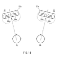
- FIG. 14 a speaker device as shown in FIG. 14 is proposed in the Patent Document 1.
- a speaker device as shown in FIG. 14
- two speaker units 56a and 56b are arranged horizontally in a cabinet 55a
- two speaker units 58a and 58b are arranged horizontally in a cabinet 57a.
- the speaker units 56a and 56b are driven with frequencies in a range of 100 Hz to 2 kHz, for example, with a predetermined phase difference being provided from each other, and so are the speaker unit 58a and 58b.
- the speaker systems 55 and 57 form dipole-like sound sources.
- This dipole-like sound source has frequency characteristics in that emission power attenuates in the mid-frequency range and below. Therefore, the frequency characteristic is corrected by a large-scale boosting on the low frequency side up to 200 Hz.
- Patent Document 1 JP 4(1992)-23399 U
- the conventional speaker device disclosed by the Patent Document 1 needs large-scale boosting on the low frequency side so as to correct the emission power attenuation characteristic of the dipole-like sound source in the mid-range and below Therefore, extremely large electric power is supplied to the speaker units 56a, 56b, 58a, and 58b, thereby damaging the speakers or distorting sounds.
- the foregoing speaker device has a problem that a high sound pressure level cannot be obtained.
- the directivity of the speaker units 56a, 56b, 58a, and 58b becomes acute in the treble range, for example, the sound pressure level in the treble range reaching the listener PL on the left side from the right-side speaker system 55 falls significantly As a result, the effect of improving the sound image localization position falls drastically in the treble range, and the effect of improving the sound image localization position cannot be achieved sufficiently.
- sounds in a low frequency band emitted from a dipole-like sound source give a sense of significant discomfort.
- a low frequency sound has an extremely long wavelength, and hence the sound emitted from each speaker unit reaches right and left ears of a human, with a phase difference being maintained completely.
- the sounds from the speaker unit 56b predominantly reach the left ear, while the sounds from the speaker unit 56a predominantly reach the right ear. Therefore, the right and left ears constantly hear sounds with phases reverse to each other, respectively, which causes the listener to feel a sense of significant discomfort.
- An object of the present invention is to provide an acoustic reproduction device that has an excellent effect in expanding a listening position range where the center sound image localization can be achieved with respect to voices such as singing and speech; and that is configured so that a center speaker for multichannel sound reproduction can be provided integrally with left-side and right-side front speaker systems.
- An acoustic reproduction device of the present invention includes: a pair of speaker systems, each speaker system having a first speaker unit and a second speaker unit; a signal processing unit that performs a predetermined processing operation with respect to an input signal; and an amplifier that amplifies an output signal from the signal processing unit, and applies the signal to the speaker systems, wherein when the pair of speaker systems are arranged symmetrically with respect to a listening center axis, the first speaker units are arranged symmetrically with respect to the listening center axis, and the second speaker units are arranged symmetrically with respect to the listening center axis.
- the first and second speaker units are arranged so that the first speaker unit emits a sound in an inward direction, and the second speaker unit emits a sound in a front direction of the speaker system or in an outward direction as compared with the direction of the first speaker unit, where the inward direction is defined as a direction toward the listening center axis from each speaker system.
- the signal processing unit is configured so as to include a first processing part that processes a center channel signal, of multichannel signals supplied as input signals, and outputs the processed signal as a signal for the first speaker unit, and a second processing part that processes the center channel signal and outputs the processed signal as a signal for the second speaker unit, and is configured to superimpose respective front channel signals, of the multichannel signals, onto the output signal of the second processing part, and supply the signals in the superimposed state to the second speaker units, respectively.
- the first processing part includes a HPF (high-pass filter) block that performs a processing operation for attenuating a low-range component of the center channel signal; and a first high-shelf block that performs a processing operation for obtaining step-like characteristics for boosting a high-range component.
- HPF high-pass filter
- the second processing part includes a LPF (low-pass filter) block that performs a processing operation for attenuating a high-range component of the center channel signal; a low-shelf block that performs a processing operation for obtaining step-like characteristics for attenuating a part of a low-range signal component, of signal components in a band below the high-range component attenuated by the low-pass filter block; and a second high-shelf block that performs a processing operation for obtaining a step-like characteristics for attenuating a part of a high-range signal component.
- LPF low-pass filter
- the acoustic reproduction device is configured so that at a listening position in a front direction of one of the speaker systems, a reproduced sound of the center channel signal arriving from the first speaker unit of the one of the speaker systems that is closer to the listening position, and a reproduced sound of the center channel signal arriving from the second speaker unit of the same speaker system, are destructive to each other in the mid-range owing to a phase difference therebetween.
- the acoustic reproduction device of the present invention may have the following various modifications based on the above-described configuration.
- the mid-range preferably is set to a frequency range including 1.5 kHz.
- the mid-range is set to a frequency range including a part or an entirety of the second formant frequency and the third formant frequency of human voice. This makes it possible to achieve an excellent effect of expanding the listening position range in which the center sound image localization can be achieved with respect to voice such as singing and speech in particular.
- the configuration may be such that the first speaker unit is arranged on an inner side with respect to the second speaker unit as viewed from the listening center axis, and in the mid-range, a phase of an emitted sound of the first speaker unit is delayed as compared with a phase of an emitted sound of the second speaker unit.
- the configuration may be such that the first speaker unit is arranged on an outer side with respect to the second speaker unit as viewed from the listening center axis, and in the mid-range, a phase of an emitted sound of the first speaker unit is advanced as compared with a phase of an emitted sound of the second speaker unit.
- first speaker unit and the second speaker unit may be arranged in a vertical relationship, whereby the speaker systems can be downsized in the width direction.
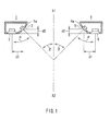
- FIG. 1 shows a configuration of a speaker device according to an Embodiment of the present invention.
- FIG. 2 is a perspective view of the forgoing speaker device.
- FIG. 3 is a network circuit diagram of the foregoing speaker device.
- FIG. 4 is a frequency characteristic diagram of each speaker unit of the foregoing speaker device.
- the left-side speaker system 1 and the right-side speaker system 4 are placed on both sides of a listening center axis X1-X2, at substantially the same distances from the listening center axis X1-X2.
- a cabinet 1a of the left-side speaker system 1 there are installed a first speaker unit 2 and a second speaker unit 3.
- a cabinet 4a of the right-side speaker system 4 there are installed a first speaker unit 5 and a second speaker unit 6.
- the arrangement of the speaker units 2, 3, 5, and 6 is symmetrical with respect to the listening center axis X1-X2.
- Each of the first speaker units 2 and 5 is, for example, a 6.5-cm-diameter full-range unit, and is sealed on the back so that its diaphragm is not vibrated by the air pressure of a bass sound in the cabinet.
- Each of the second speaker units 3 and 6 is a 8-cm-diameter bass-range unit, for example.
- the first speaker units 2 and 5 are positioned on inner sides with respect to the second speaker units 3 and 6, respectively, and are arranged so as to emit sounds in the inward direction.
- the second speaker units 3 and 6 are arranged so as to emit sounds in a front direction, and hence, they emit sounds in directions outward with respect to the directions of the first speaker units 2 and 5, respectively
- Angles ⁇ of the sound emission direction of each of the first speaker units 2 and 5 with respect to the listening center axis X1-X2 are approximately 45°. Therefore, each angle ⁇ between the sound emission directions of the second speaker units 3 and 6 and the sound emission directions of the first speaker units 2 and 5, respectively, is approximately 45°.
- a distance d1 in the horizontal direction between the first speaker units 2 and 5 and the second speaker units 3 and 6, respectively, is approximately 9 cm, and a distance d2 in the depth direction therebetween is approximately 4 cm.
- the first speaker units 2 and 5 and the second speaker units 3 and 6 are arranged horizontally as shown in the perspective view of FIG. 2 .
- signals to drive this speaker device are supplied via a 6-dB/oct-type network circuit composed of a low-range cut-off capacitor C and a high-range cut-off coil L.
- signals whose low range is attenuated are fed to the first speaker units 2 and 5, while signals whose high range is attenuated are fed to the second speaker units 3 and 6.
- the first speaker units 2 and 5 and the second speaker units 3 and 6 are connected to a network circuit, with polarities reverse to each other, respectively
- Frequency characteristics of the speaker units 2, 3, 5, and 6 at the same measurement distances on the axes are as shown in FIG. 4 .
- Sound pressure frequency characteristics of the first speaker units 2 and 5 are indicated with a broken line B, and a phase frequency characteristic thereof is indicated with a broken line D.
- a sound pressure frequency characteristic of the second speaker units 3 and 6 is indicated with a solid line A, and a phase frequency characteristic thereof is indicated with a solid line C.
- the frequency characteristics in FIG. 4 show a synergistic effect of characteristics of the speaker units 2, 3, 5, and 6, and division characteristic of the network circuit shown in FIG. 3 .
- the first speaker units 2 and 5 have a reproduction frequency band of not lower than about 500 Hz (-6 dB), as indicated by the broken line B.
- the second speaker units 3 and 6 have a reproduction frequency band ranging from a bass range to about 4 kHz (-6 dB), as indicated by the solid line A Therefore, mid-range sounds of about 500 Hz to 4 kHz are reproduced by both of the first speaker units 2 and 5 and the second speaker units 3 and 6.
- the sound pressure level of the first speaker units 2 and 5 is set slightly lower than that of the second speaker units 3 and 6. This is intended to adjust the effect of the center sound image localization, as described below.
- FIG. 5 is a frequency characteristic diagram of the speaker device configured as described above.
- FIG. 6 is an explanatory view showing the operation of the foregoing speaker device in the mid-range, and
- FIG. 7 is an explanatory view showing the operation of the foregoing speaker device in the treble range.
- a solid line P 1 represents a sound pressure frequency characteristic of the speaker system 1 (or 4) in the front direction of the first speaker unit 2 (or 5), as shown in a reference drawing in FIG. 5 .
- Abroken line P2 represents sound pressure frequency characteristic of the speaker system 1 (4) in the front direction of the second speaker unit 3 (6), in other words, in the front direction of the speaker system 1 (4).
- the following characteristics are obtained: a high sound pressure level is obtained in the front direction of the first speaker unit 2 (P1), while the sound pressure level significantly attenuates in the mid-range band and above in the front direction of the speaker system 1 (P2).
- an emitted sound in a mid-range of several hundreds Hz which is a middle range of a reproduction band, has a phase of about 0°.
- This phase is delayed by about 90° toward the treble range by a 6-dB/oct-type low-pass filter (high-cut) network circuit ( FIG. 3 ).
- the reason why the phase advances in the bass range is that attenuation occurs in the low frequency range.
- a phase frequency characteristic thereof delays by 180° in the treble range as represented by a dotted line D in FIG. 4 .
- the phase thereof would be 0° in the treble range.
- the phase advances by about 90° toward the bass range side by the 6-dB/oct-type high-pass filter (low-cut) network circuit, and the phase further advances due to the attenuation in the bass range of the speaker units 2 and 5 themselves.
- the phase (the dotted line D) of the emitted sound of the first speaker units 2 and 5 has a delay of about 90° as compared with the phase of the emitted sound of the second speaker units 3 and 6.
- the sound pressure frequency characteristic of the speaker system 1 (4) in the vicinity of the front direction of the first speaker unit 2 (5) is such a characteristic, obtained by adding respective sound pressures of the first speaker unit 2 (5) and the second speaker unit 3 (6), as represented by the solid line P 1 shown in FIG. 5 .
- the sound pressure frequency characteristic of the speaker system 1 (4) in the vicinity of the front direction of the second speaker unit 3 (6) is such a characteristic having level attenuation in a range from the mid-range to the treble range as represented by the dotted line P2 in FIG. 5 .
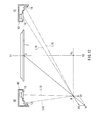
- FIG. 6 a display 7 is installed at the midpoint between the left-side speaker system 1 and the right-side speaker system 4, and a center position of the display 7 is denoted as S.
- An ideal center listening position Pc lies on the listening center axis X1-X2. Assume that an actual listening position P lies approximately in the front direction of the speaker system 1 closer thereto.
- Each of the speaker systems 1 and 4 is similar to that shown in FIG. 1 .
- This standard arrangement is recommended not only for the conventional 2-channel stereo reproduction, but also for multichannel speaker systems in the ITU-R Recommendations.
- a distance L5 from the first speaker unit 5 of the speaker system 4, which is farther from the listening position P, to the listening position P is shorter than a distance L6 from the second speaker unit 6 to the listening position P.
- the distance L5 is about 4 cm shorter than the distance L6.
- phase of the emitted sound of the first speaker unit 5 delays by about 90° in the mid-range originally (immediately after the emission from the speaker unit) as compared with the phase of the emitted sound of the second speaker unit 6, the phase difference at the listening point P between the respective arriving sounds from the foregoing units is caused to decrease due to L5 being shorter than L6.
- the phase difference between the arriving sound from the first speaker unit 5 and the arriving sound from the second speaker unit 6 approaches 0°, whereby both the emitted sounds are constructive each other.
- the distance L2 from the first speaker unit 2 to the listening position P is greater than the distance L3 from the second speaker unit 3 to the listening position P.
- the distance L2 is about 4 cm longer than the distance L3.
- phase difference at the listening point P between the respective arriving sounds from the foregoing units is caused to increase due to L3 being shorter than L2.
- the phase difference between the arriving sound from the first speaker unit 5 and the arriving sound from the second speaker unit 6 approaches 180°, whereby both the emitted sounds are destructive to each other.
- the above effect is maximized at the frequency with which a sound wave has a phase rotation of 90° due to the distance difference between L5 and L6 or the distance difference between L2 and L3, that is, at the frequency with which the distance difference becomes equal to 1/4 the wavelength of the sound.
- the distance difference between L5 and L6 and the distance difference between L2 and L3 are 4 cm each. Therefore, the above-described effect is maximized in the vicinity of 2 kHz at which 4 cm is equivalent to 1/4 wavelength. As the frequency decreases from the vicinity of 2 kHz, this effect gradually decreases. This applies to the speaker system 1 closer to the listening position P similarly.
- the sound wave has a phase advance of 180° due to the distance difference, whereby the phase of the arriving sound from the first speaker unit 5 to the listening position P advances by 90° with respect to the phase of the arriving sound from the second speaker unit 6 to the listening position P.
- the arriving sound from the first speaker unit 5 and the arriving sound from the second speaker unit 6 are not constructive to each other, and hence, the above-described effect is minimized.
- a sound wave has a phase advance of 270° due to the foregoing distance difference, and hence, the phase of the arriving sound from the first speaker unit 5 to the listening position P advances by 180° as compared with the phase of the arriving sound from the second speaker unit 6 to the listening position P.
- the emitted sound of the first speaker unit 5 and the emitted sound of the second speaker unit 6 cancel each other; this is the inverse of the intended effect.
- the treble range of the second speaker units 3 and 6 are attenuated, as represented by the solid line A of FIG. 4 .
- a sound pressure vector V1 of the speaker system 1 closer to the listening position P can be decreased significantly as compared with a sound pressure vector V2 of the speaker system 4 farther from the listening position P.
- a sound image in the mid-range can be localized in the vicinity of the center position S of the display 7.
- the direction of sound emission from the first speaker unit 5 farther from the listening position P is in the vicinity of the front direction of the listening position P.
- the direction of sound emission of the first speaker unit 2 closer to the listening position P is tilted significantly with respect to the listening position P. Therefore, sounds from the first speaker unit 5 farther from the listening position P are not caused to have the treble-range attenuation due to the directivity characteristic of the first speaker unit 5.
- sounds from the first speaker unit 2 closer to the listening position P are caused to have the treble-range attenuation significantly due to the directivity characteristic of the first speaker unit 2.
- the sound pressure vector V1 in the treble range of the first speaker unit 2 closer to the listening position P can be decreased significantly, as compared with the sound pressure vector V2 in the treble range of the first speaker unit 5 farther from the listening position P. Consequently, a sound image in the treble range can be localized in the vicinity of the center position S of the display 7.
- the effect based on the directivity of the first speaker units 2 and 5 is utilized as a result, an effect of sufficiently decreasing the sound pressure vector V1 of the speaker system 1 closer to the listening position P as compared with the sound pressure vector V2 of the speaker system 4 farther from the listening position P can be obtained over the entire frequency band in the mid-range and above.
- an attenuated sound pressure level of the sound pressure vector V1 of the speaker system 1 closer to the listening position P should have a smaller difference from a sound pressure level of the sound pressure vector V2 of the speaker system 4 farther from the listening position P.
- the sound pressure level difference is about 4 dB in order to achieve a sufficient effect.
- the difference between the distance to the listening position P from the first speaker units 2 and 5 and the distance thereto from the second speaker units 3 and 6 decreases roughly proportionally Therefore, in the mid-range, the phase rotation amount of a sound wave owing to the distance difference decreases roughly proportionally, and the interference effect between arriving sounds owing to the phase rotation also decreases, whereas a sound pressure level difference required for localizing a sound image in the vicinity of the center also decreases roughly proportionally.
- the listening position range where the center sound image localization can be achieved can be expanded to the full distance between the speaker systems 1 and 4.
- the following describes results of analytical calculation regarding the case where the listening position P moves outward from the vicinity of the front of the speaker system 1. For example, when the listening position P moved to the left side by about Wx 1/2 from the position in the front direction of the speaker system 1 closer to the listening position P, the above-described required sound pressure level difference was found to be about 9.5 dB.
- the listening position range in which the center sound image localization is achieved can be expanded beyond the range extending between the speaker systems 1 and 4.
- the sound pressure level difference for obtaining the center sound image localization is set slightly greater than the above-described value.
- the above-described sound pressure level difference is excessively great, in some cases a sound image is localized at a position deviated, over the vicinity of the center, toward the speaker system farther from the listening position. In such a case, a small level difference may be provided between the sound pressure level of the first speaker unit 2 and 5 and the sound pressure level of the second speaker units 3 and 6 in the mid-range.
- the speaker device of the present embodiment is configured so that, as shown in FIG. 5 , in the frequency band of about 1 kHz and above, the sound pressure vector V1 of the speaker system 1 closer to the listening position P is significantly smaller than the sound pressure vector V2 of the speaker system 4 farther from the listening position P.
- Basic frequencies of human voices are about 80 Hz to 400 Hz for male voices, and about 150 Hz to 900 Hz for female and child voices, which are rather close to the bass range. It is known, however, that apart from these, there are peculiar frequency spectra called "formants", which characterize human voices, and that the formants of vowels are important particularly.
- the formants are called “first formant”, “second formant”, and “third formant” in the frequency ascending order. Irrespective of the language, for the male, female, and child voices in general, the range of the first formant frequency is about 300 Hz to 1 kHz. The range of the second formant frequency is about 800 Hz to 3 kHz, and the range of the third formant frequency is about 2.5 kHz to 4 kHz.
- An acoustic reproduction device in an Embodiment of the present invention is configured so that each of the speaker systems included in the above-described speaker devices is configured so as to function as both a center speaker and a front speaker system for multichannel reproduction at the same time.
- the acoustic reproduction device having such a configuration is described with reference to FIG. 8 .
- the device shown in FIG. 8 has a configuration for allowing the same speaker systems 11 and 14 as the speaker systems 1 and 4 shown FIG. 1 to function as a center speaker and a front speaker system, when the speaker systems 11 and 14 are driven with signals having been subjected to the same signal processing as that of the network circuit shown in FIG. 3 .
- This configuration corresponds to a preliminary stage for an Embodiment of the present invention.
- a left-side speaker system 11 is provided with a first speaker unit 12 and a second speaker unit 13.
- Aright-side speaker system 14 is provided with a first speaker unit 15 and a second speaker unit 16.
- the arrangement relationship of the first speaker units 12 and 15 and the second speaker units 13 and 16 is similar to that of the speaker device shown in FIG. 1 .
- each of the first speaker units 12 and 15 is, for example, a 6.5-cm-diameter full-range unit
- each of the second speaker units 13 and 16 is, for example, a 8-cm-diameter full-range unit.
- a center channel signal supplied to a terminal TC is divided into signals for two paths.
- Acenter channel signal supplied to one of the two paths is inputted to a 6-dB/oct-type HPF (high-pass filter) 17, so that a part thereof in the mid-range and the treble range is passed through, then a phase thereof is inverted by an inverter 18.
- the signal is amplified by a center channel amplifier (C) 19, and drives the first speaker units 12 and 15.
- Acenter channel signal supplied to the other path is inputted to a 6-dB/oct-type LPF (low-pass filter) 20, so that a part thereof in the treble range is attenuated, then the signal is amplified by front channel amplifiers (R+C) 21 and (L+C) 22, so as to drive the second speaker units 13 and 16.
- LPF low-pass filter
- a front R channel signal and a front L channel signal fed via terminals TR and TL are fed to the amplifier (R+C) 21 and the amplifier (L+C) 22, respectively, and drive the second speaker units 13 and 16, respectively
- each of the second speaker units 13 and 16 is fed with a superimposed signal of the center channel signal with the treble range attenuated and the front channel signal, and reproduces both signals together.
- the characteristics of input signals applied to the first speaker units 12 and 15 and the second speaker units 13 and 16 are similar to those of the speaker device described in the above "Basic Concept" section. Therefore, the operation and effect described above are exhibited with respect to the center channel signal, whereby an excellent effect of expanding the listening position range in which the center sound image localization can be achieved with respect to audio signals on the center channel can be achieved.
- an acoustic reproduction device that reproduces the center channel and the front L and R channels can be obtained with a total of four speaker units, which is the minimum number of speaker units.
- the center speaker system is configured integrally with the front speaker system, there is no need to install an independent center speaker system.
- This configuration makes control easier when a sufficient distance in the horizontal direction can be ensured between the first speaker unit 12 (15) configured to be directed inward and the second speaker unit 13 (16) configured to be directed forward.
- the following problem arises.
- a cabinet is configured to be long in the vertical direction in some cases, taking into consideration the convenience of placing the speaker device.
- a first speaker unit 24 and a second speaker unit 25 are arranged so that the first speaker unit 24 emits sounds in an inward direction and the second speaker unit 25 emits sounds toward the vicinity in a front direction.
- the first speaker unit 24 and the second speaker unit 25 are installed in a cabinet 23a so that they are arranged in a vertical relationship. This configuration makes it possible to downsize the speaker system 23 in the width direction.
- the first speaker unit 24 and the second speaker unit 25 are close to each other in the horizontal direction. Therefore, it is difficult to make a distance therebetween in the horizontal direction sufficient, the distance being equivalent to the distance d1 in the horizontal direction between the first speaker unit 2 and the second speaker unit 3 shown in FIG. 1 . As a result, it is difficult to adjust a sound pressure using a difference between a distance from the first speaker unit 24 to the listening position P and a distance from the second speaker unit 25 to the listening position P.
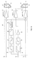
- a signal processing unit 30 as shown in FIG. 10 is used in place of the signal processing unit in the acoustic reproduction device shown in FIG. 8 .
- the signal processing unit 30 includes a first processing part 31 and a second processing part 32, and desirably is composed of a DSP (digital signal processor).
- DSP digital signal processor
- the configuration of the acoustic reproduction device shown in FIG. 10 is particularly advantageous when it is applied to the speaker system 23 shown in FIG. 9 , but for convenience of illustration, the same configuration using the speaker systems 11 and 12 as that shown in FIG. 8 is illustrated.
- a first speaker unit 12 and a second speaker unit 13 are installed in a left-side speaker system 11.
- a first speaker unit 15 and a second speaker unit 16 are installed in a right-side speaker system 14.
- the arrangement relationship of the first speaker units 12 and 15 and the second speaker units 13 and 16 may be similar to that of the speaker device shown in FIG. 9 .
- a center channel signal supplied to a terminal TC is divided into signals for two paths.
- a center channel signal supplied to one of the two paths is processed by the first processing part 31 and is amplified by an amplifier (C) 19, so as to drive the first speaker units 12 and 15.
- the first processing part 31 is composed of a HPF block 33, a first high-shelf block 34, and a phase inversion block 35.
- a center channel signal supplied to the other path is processed by the second processing part 32 and is amplified by an amplifier (R+C) 18 and an amplifier (L+C) 19, so as to drive the second speaker units 13 and 16.
- the second processing part 32 is composed of a low-shelf block 36, a second high-shelf block 37, a LPF block 38, and a level adjustment block 39.
- a front R channel signal and a front L channel signal fed via terminals TR and TL are amplified by the amplifier (R+C) 21 and the amplifier (L+C) 22, respectively, and drive the second speaker units 13 and 16, respectively.
- the center channel signal having been processed by the second processing part 32 and front channel signals are fed in a superimposed state, and are reproduced together.
- the HPF block 33 cuts off low frequencies.
- the first high-shelf block 34 performs a processing operation for obtaining a step-like characteristics such that a level of a signal in a high range higher than a cut-off frequency is boosted.
- the low-shelf block 36 performs a processing operation for obtaining a step-like characteristics such that a level of a signal in a middle and low range lower than a cut-off frequency is dropped.
- the second high-shelf block 37 performs a processing operation for obtaining a step-like characteristics such that a level of a signal in a high range higher than a cut-off frequency is dropped
- the LPF block 38 cuts offhigh frequencies.
- Exemplary coefficients set for the blocks are shown in Table 1 below, which are set in the case of an acoustic reproduction device configured so that 6.5-cm-diameter cone-type speaker units are used for the first speaker units 12 and 15 and the second speaker units 13 and 16, and a distance in the horizontal direction between the first speaker unit 12 (15) and the second speaker unit 13 (16) is set at 20 mm.
- the order of each filter or the like is the second order.
- FIG. 11 shows frequency characteristics of a signal supplied to the amplifier (C) 19 (a signal for the first speaker units 12, 15) and frequency characteristics of a mixed signal supplied to the amplifiers (R+C) 18 and (L+C) 19 (a signal for the second speaker units 13, 16) obtained in this configuration.
- a level frequency characteristic of the signal for the first speaker units 12 and 15 is indicated by a broken line A1, and a phase frequency characteristic thereof is indicated by a broken line PH1.
- Alevel frequency characteristic of the signal for the second speaker units 13 and 16 is indicated by a solid line A2, and a phase frequency characteristic thereof is indicated by a solid line PH2.
- the low-shelf block 36 has a function of adjusting a level and a phase of a middle- and low-range component of a signal allocated to the second speaker units 13 and 16, and in the relationship with the signal supplied to the first speaker units 12 and 15, the low-shelf block 36 makes a significant contribution to the flattening of the total frequency characteristic for frequencies of 2 kHz or lower.
- the phase characteristic also varies as indicated by a reference numeral "a”. Therefore, the relationship with the level and phase of the signal applied to the first speaker units 12 and 15 may be adjusted minutely by the setting of the cut-off frequency and the value Q, whereby a flat total frequency characteristic can be obtained.
- the first high-shelf block 34 has a function of correcting energy in the high range of a signal for the first speaker units 12 and 15 (high range boosting). However, as indicated by a reference numeral "b" in FIG. 11 , the phase characteristic also varies. Therefore, the second high-shelf block 37 appropriately controls the phase of the signal applied to the second speaker units 13 and 16, as indicated by a reference numeral "c", in a frequency band in which the phase characteristic of the signal applied to the first speaker units 12 and 15 varies. This allows the minute adjustment for obtaining the flat total frequency characteristic for frequencies of 2 kHz or lower as described above to be carried out.
- a decrease in this angle ⁇ allows the dimensions in the front-back direction of the speaker systems 11 and 14 to decrease.
- the listening position at which the effect of the present invention can be achieved is located at a position in the front-back direction far from the speaker systems 11 and 14. Therefore, the angle ⁇ may be determined with the dimensions required of the speaker systems and the desired listening position range being taken into consideration.
- the sound emission direction of the second speaker units 13 and 16 may be any direction as long as it is outward as compared with the sound emission direction of the first speaker units 12 and 15, and are not necessarily a completely front direction. Further, if an angle ⁇ (see FIG. 1 ) between the sound emission directions of the second speaker units 13 and 16 and the sound emission directions of the first speaker units 12 and 15, respectively, is set at 15° to 90°, it is possible to achieve an effect as described above.
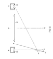
- the speaker units may be arranged as shown in FIG. 12 .
- first speaker units 12 and 15 and second speaker units 13 and 16 are the same as those shown in FIG. 10
- a display 17 is the same as that shown in FIG. 6 .
- This arrangement is different from the case shown in FIG. 10 in the shape of the left-side speaker system 40 and the shape of the right-side speaker system 41, i.e., the shapes of cabinets 42 and 43, and the arrangement relationship of the speaker units 12, 13, 15, and 16.
- the first speaker units 12 and 15 are arranged on outer sides with respect to the second speaker units 13 and 16, respectively, and are arranged so as to emit sounds in inward directions.
- the second speaker units 13 and 16 are arranged so as to emit sounds in the front direction, and to emit sounds in outward directions as compared with the first speaker units 12 and 15, respectively.
- Each angle of the sound emission directions of the first speaker units 12 and 15 with respect to the listening center axis X1-X2 is approximately 45°.
- a distance L15 to the listening position P from the first speaker unit 15 of the right-side speaker system 14 farther from the listening position P becomes about 4 cm longer than a distance L16 from the second speaker unit 16 to the listening position P, as shown in FIG. 12 .
- a distance L12 to the listening position P from the first speaker unit 12 of the left-side speaker system 40 closer to the listening position P is about 4 cm shorter than a distance L 13 to the listening position P from the second speaker unit 13.
- the phase of an emitted sound of the first speaker units 12 and 15 is caused to advance by about 90° in a range from the mid-range to the treble range as compared with the phase of an emitted sound of the second speaker units 13 and 16.
- phase difference therebetween at the listening position P decreases. This causes a phase difference between a sound having arrived from the first speaker unit 15 and a sound having arrived from the second speaker unit 16 to approach 0°, whereby both the emitted sounds are constructive to each other.
- the same operation and effect as those in the above-described case can be achieved.
- phase difference therebetween at the listening position P increases. This causes the phase difference between a sound arriving from the first speaker unit 15 and a sound arriving from the second speaker unit 16 to approach 180°, whereby both the emitted sounds are destructive to each other.
- the same operation and effect as those described with reference to FIG. 6 can be achieved Besides, in this configuration, since the first speaker units 12 and 15 are arranged on outer sides with respect to the second speaker units 13 and 16, respectively, the emitted sounds of the first speaker units 12 and 15 become less obstructed by the display Therefore, the left-side speaker system 40 and the right-side speaker system can be disposed further back.
- the acoustic reproduction device of the present invention has an excellent effect of expanding the listening position range in which the center sound image localization can be achieved with respect to a voice such as singing voice or speech also, and is configured so that a center speaker for multichannel reproduction can be provided integrally with left-side and right-side front speaker systems. Therefore, the acoustic reproduction device of the present invention is useful, not only for sound reproduction of general two-channel stereophonic reproduction equipment or multichannel sound reproduction equipment, but also for sound reproduction of electronic equipment in general, such as sound reproduction equipment for television, on-vehicle sound reproduction equipment, sound reproduction equipment built in personal computers, and portable sound reproduction equipment.
Landscapes
- Physics & Mathematics (AREA)
- Engineering & Computer Science (AREA)
- Acoustics & Sound (AREA)
- Signal Processing (AREA)
- Health & Medical Sciences (AREA)
- Otolaryngology (AREA)
- General Health & Medical Sciences (AREA)
- Stereophonic System (AREA)
- Obtaining Desirable Characteristics In Audible-Bandwidth Transducers (AREA)
Applications Claiming Priority (2)
| Application Number | Priority Date | Filing Date | Title |
|---|---|---|---|
| JP2007107370A JP4418479B2 (ja) | 2007-04-16 | 2007-04-16 | 音響再生装置 |
| PCT/JP2008/000490 WO2008129767A1 (ja) | 2007-04-16 | 2008-03-07 | 音響再生装置 |
Publications (2)
| Publication Number | Publication Date |
|---|---|
| EP2139267A1 true EP2139267A1 (de) | 2009-12-30 |
| EP2139267A4 EP2139267A4 (de) | 2012-01-11 |
Family
ID=39875304
Family Applications (1)
| Application Number | Title | Priority Date | Filing Date |
|---|---|---|---|
| EP08720376A Withdrawn EP2139267A4 (de) | 2007-04-16 | 2008-03-07 | Akustische wiedergabeanordnung |
Country Status (4)
| Country | Link |
|---|---|
| US (1) | US20100119091A1 (de) |
| EP (1) | EP2139267A4 (de) |
| JP (1) | JP4418479B2 (de) |
| WO (1) | WO2008129767A1 (de) |
Families Citing this family (3)
| Publication number | Priority date | Publication date | Assignee | Title |
|---|---|---|---|---|
| JP2013146051A (ja) * | 2011-12-15 | 2013-07-25 | Tei Co Ltd | スピーカシステム |
| JP6012343B2 (ja) * | 2012-09-03 | 2016-10-25 | 日本放送協会 | 音響再生環境提示装置および音響再生環境提示プログラム |
| US9973851B2 (en) * | 2014-12-01 | 2018-05-15 | Sonos, Inc. | Multi-channel playback of audio content |
Family Cites Families (12)
| Publication number | Priority date | Publication date | Assignee | Title |
|---|---|---|---|---|
| JPS51163901U (de) * | 1975-06-19 | 1976-12-27 | ||
| DE3233990C2 (de) | 1982-09-14 | 1986-11-06 | Paul Dipl.-Ing. Dr.-Ing. 5100 Aachen Scherer | Verfahren und Vorrichtungen zur verbesserten Wiedergabe von Phantomschallquellen |
| JPS60261299A (ja) | 1984-06-07 | 1985-12-24 | Pioneer Electronic Corp | スピ−カシステム |
| JPS6154800A (ja) * | 1984-08-27 | 1986-03-19 | Pioneer Electronic Corp | ステレオ用スピ−カシステム |
| DE3688606T2 (de) * | 1985-04-12 | 1993-11-25 | Mitsubishi Electric Corp | Lautsprechersystem. |
| US4723289A (en) * | 1986-03-17 | 1988-02-02 | Bose Corporation | Stereo electroacoustic transducing |
| US4764960A (en) * | 1986-07-18 | 1988-08-16 | Nippon Telegraph And Telephone Corporation | Stereo reproduction system |
| JPS6326197A (ja) * | 1986-07-18 | 1988-02-03 | Nippon Telegr & Teleph Corp <Ntt> | ステレオ再生装置の調整方法 |
| JPH02228200A (ja) * | 1989-03-01 | 1990-09-11 | Matsushita Electric Ind Co Ltd | 音響再生システム内蔵型テレビセット |
| JPH0423399U (de) * | 1990-06-18 | 1992-02-26 | ||
| US5557680A (en) * | 1995-04-19 | 1996-09-17 | Janes; Thomas A. | Loudspeaker system for producing multiple sound images within a listening area from dual source locations |
| JP2004247890A (ja) * | 2003-02-13 | 2004-09-02 | Sony Corp | テレビジョン受像機のスピーカ装置 |
-
2007
- 2007-04-16 JP JP2007107370A patent/JP4418479B2/ja not_active Expired - Fee Related
-
2008
- 2008-03-07 US US12/596,029 patent/US20100119091A1/en not_active Abandoned
- 2008-03-07 EP EP08720376A patent/EP2139267A4/de not_active Withdrawn
- 2008-03-07 WO PCT/JP2008/000490 patent/WO2008129767A1/ja not_active Ceased
Also Published As
| Publication number | Publication date |
|---|---|
| US20100119091A1 (en) | 2010-05-13 |
| WO2008129767A1 (ja) | 2008-10-30 |
| EP2139267A4 (de) | 2012-01-11 |
| JP4418479B2 (ja) | 2010-02-17 |
| JP2008270909A (ja) | 2008-11-06 |
Similar Documents
| Publication | Publication Date | Title |
|---|---|---|
| EP2009957B1 (de) | Lautsprechereinrichtung | |
| EP3439330B1 (de) | Einstellung der wahrgenommenen höhe eines audiobildes auf einer festen kinoleinwand | |
| US8369533B2 (en) | Array speaker apparatus | |
| US5870484A (en) | Loudspeaker array with signal dependent radiation pattern | |
| CN104641659B (zh) | 扬声器设备和音频信号处理方法 | |
| JP2708105B2 (ja) | 車載用音響再生装置 | |
| US10645521B2 (en) | Stereo and filter control for multi-speaker device | |
| EP3061268B1 (de) | Verfahren und mobile vorrichtung zur verarbeitung eines audiosignals | |
| JP5788894B2 (ja) | サラウンドサウンド生成のためのマルチチャンネルオーディオ信号を処理するための方法およびオーディオシステム | |
| KR20190062902A (ko) | 오디오 신호 출력 장치 및 방법, 이를 이용한 디스플레이 장치 | |
| US8411884B2 (en) | Audio reproduction device and audio-video reproduction system | |
| JP6380060B2 (ja) | スピーカ装置 | |
| TWI411315B (zh) | 具有大型感知聲頻規模及音像之小型音頻播放系統 | |
| EP2139267A1 (de) | Akustische wiedergabeanordnung | |
| US7676049B2 (en) | Reconfigurable audio-video surround sound receiver (AVR) and method | |
| US8009834B2 (en) | Sound reproduction apparatus and method of enhancing low frequency component | |
| JP2012195800A (ja) | スピーカ装置 | |
| JPH09252500A (ja) | 音響機器におけるステレオ再生方式 | |
| KR101758056B1 (ko) | 스테레오 정위감 제공 일체형 스피커 |
Legal Events
| Date | Code | Title | Description |
|---|---|---|---|
| PUAI | Public reference made under article 153(3) epc to a published international application that has entered the european phase |
Free format text: ORIGINAL CODE: 0009012 |
|
| 17P | Request for examination filed |
Effective date: 20091116 |
|
| AK | Designated contracting states |
Kind code of ref document: A1 Designated state(s): AT BE BG CH CY CZ DE DK EE ES FI FR GB GR HR HU IE IS IT LI LT LU LV MC MT NL NO PL PT RO SE SI SK TR |
|
| DAX | Request for extension of the european patent (deleted) | ||
| A4 | Supplementary search report drawn up and despatched |
Effective date: 20111208 |
|
| RIC1 | Information provided on ipc code assigned before grant |
Ipc: H04S 1/00 20060101ALI20111202BHEP Ipc: H04R 5/02 20060101ALI20111202BHEP Ipc: H04R 1/34 20060101ALI20111202BHEP Ipc: H04R 3/12 20060101ALI20111202BHEP Ipc: H04S 3/00 20060101AFI20111202BHEP Ipc: H04R 1/26 20060101ALI20111202BHEP |
|
| RIC1 | Information provided on ipc code assigned before grant |
Ipc: H04R 1/34 20060101ALI20120730BHEP Ipc: H04R 5/02 20060101ALI20120730BHEP Ipc: H04R 1/26 20060101ALI20120730BHEP Ipc: H04S 3/00 20060101AFI20120730BHEP Ipc: H04R 3/12 20060101ALI20120730BHEP Ipc: H04S 1/00 20060101ALI20120730BHEP |
|
| GRAP | Despatch of communication of intention to grant a patent |
Free format text: ORIGINAL CODE: EPIDOSNIGR1 |
|
| STAA | Information on the status of an ep patent application or granted ep patent |
Free format text: STATUS: THE APPLICATION HAS BEEN WITHDRAWN |
|
| 18W | Application withdrawn |
Effective date: 20120903 |