EP2139200A2 - WSN-basierte kontextsensible Maschine - Google Patents
WSN-basierte kontextsensible Maschine Download PDFInfo
- Publication number
- EP2139200A2 EP2139200A2 EP09163611A EP09163611A EP2139200A2 EP 2139200 A2 EP2139200 A2 EP 2139200A2 EP 09163611 A EP09163611 A EP 09163611A EP 09163611 A EP09163611 A EP 09163611A EP 2139200 A2 EP2139200 A2 EP 2139200A2
- Authority
- EP
- European Patent Office
- Prior art keywords
- data
- context
- sensor
- unit
- group
- Prior art date
- Legal status (The legal status is an assumption and is not a legal conclusion. Google has not performed a legal analysis and makes no representation as to the accuracy of the status listed.)
- Withdrawn
Links
Images




Classifications
-
- H—ELECTRICITY
- H04—ELECTRIC COMMUNICATION TECHNIQUE
- H04L—TRANSMISSION OF DIGITAL INFORMATION, e.g. TELEGRAPHIC COMMUNICATION
- H04L12/00—Data switching networks
- H04L12/28—Data switching networks characterised by path configuration, e.g. LAN [Local Area Networks] or WAN [Wide Area Networks]
-
- H—ELECTRICITY
- H04—ELECTRIC COMMUNICATION TECHNIQUE
- H04L—TRANSMISSION OF DIGITAL INFORMATION, e.g. TELEGRAPHIC COMMUNICATION
- H04L67/00—Network arrangements or protocols for supporting network services or applications
- H04L67/01—Protocols
- H04L67/12—Protocols specially adapted for proprietary or special-purpose networking environments, e.g. medical networks, sensor networks, networks in vehicles or remote metering networks
-
- G—PHYSICS
- G06—COMPUTING OR CALCULATING; COUNTING
- G06Q—INFORMATION AND COMMUNICATION TECHNOLOGY [ICT] SPECIALLY ADAPTED FOR ADMINISTRATIVE, COMMERCIAL, FINANCIAL, MANAGERIAL OR SUPERVISORY PURPOSES; SYSTEMS OR METHODS SPECIALLY ADAPTED FOR ADMINISTRATIVE, COMMERCIAL, FINANCIAL, MANAGERIAL OR SUPERVISORY PURPOSES, NOT OTHERWISE PROVIDED FOR
- G06Q50/00—Information and communication technology [ICT] specially adapted for implementation of business processes of specific business sectors, e.g. utilities or tourism
- G06Q50/02—Agriculture; Fishing; Forestry; Mining
-
- H—ELECTRICITY
- H04—ELECTRIC COMMUNICATION TECHNIQUE
- H04L—TRANSMISSION OF DIGITAL INFORMATION, e.g. TELEGRAPHIC COMMUNICATION
- H04L67/00—Network arrangements or protocols for supporting network services or applications
- H04L67/50—Network services
- H04L67/60—Scheduling or organising the servicing of application requests, e.g. requests for application data transmissions using the analysis and optimisation of the required network resources
- H04L67/63—Routing a service request depending on the request content or context
Definitions
- the present disclosure relates to a context-awareness engine, and more particularly, to a context-awareness engine for processing sensed data and perceiving context under the wireless sensor network (WSN) environment.
- WSN wireless sensor network
- a WSN or a ubiquitous sensor network refers to one of main technologies of the ubiquitous system in which various sensors sense data and transmit the sensed data to a corresponding computer through a network and the sensor middleware of the computer intelligently analyzes the sensed data. That is, the WSN or USN technology adds a network concept to the sensor which senses circumferential physical phenomena and manages and controls information sensed by the sensor in real time in association with the network.
- an aspect of the present disclosure is to provide a context-awareness engine, which can analyze sensed data more specifically and perceive context more accurately.
- a context-awareness engine including a spatial filtering unit which applies spatial filtering to sensed data which is output from sensors included in a group to filter data in which an error is not generated, a conditional decision unit which compares the filtered data with at least one condition to determine a current state of a place corresponding to the group, and a result processing unit which combines the determined current state and information regarding the group to generate a context-awareness result.
- the spatial filtering unit may include an identification unit which compares a sensor which outputs the sensed data and a sensor included in the group to identify an operated sensor and a non-operated sensor, and an error data removal unit which removes error data from the data which is sensed by the operated sensor, and outputs the data in which the error is not generated to the conditional decision unit.
- the spatial filtering unit may further include an administrator confirmation module which notifies an administrator of an alarming message based on identification information regarding the non-operated sensor and the sensor which outputs the error data.
- the at least one condition may include a duration, a range of sensed data, and a state which corresponds to the duration and the sensed data, and if a plurality of conditions is provided, the conditional decision unit may determine a state corresponding to a condition of the plurality of conditions that conforms to the filtered data as the current state.
- the context-awareness engine may further include a temporal decision unit which re-determines the current state using the filtered data and stored past data to output a final decision result.
- the temporal decision unit may compare the past data, a regulation which is extracted based on the past data, and the filtered data which is input from the conditional decision unit to re-determine the current state.
- the extracted regulation may comprise a range of past data corresponding to a normal state, a range of past data corresponding to an abnormal state, a normal variation in the past data, and an upper limit value and a lower limit value of the past data.
- the temporal decision unit may compare the filtered data and the stored past data to re-determine the current state.
- the result of re-determination may be one of normal, caution, attention, warning, danger and user-defined state, and the result processing unit may selectively provide an administrator with an alarming message according to the result of re-determination.
- the result processing unit may combine one of the determined current state and the re-determined current state with identification information of the group, a time during which the data is sensed, and identification information of the sensor which senses the data to generate a context-awareness result.
- the group may be a set of sensors which are installed in the same place and have the same operational condition.
- FIG. 1 is a block diagram illustrating a context-awareness system to which a context-awareness engine is applied according to an exemplary embodiment of the present disclosure
- FIG. 2 illustrates the sensor environment registry module and the context-awareness engine of FIG. 1 in detail.
- the context-awareness system refers to a system which uses a sensor middleware to intelligently analyze sensed data in the WSN or USN environment.
- the context-awareness system designates a plurality of groups including at least one sensor and perceives context in the unit of group.
- the context-awareness system determines the current state of a place corresponding to the group by applying spatial filtering and conditional decision to the data sensed by the sensor of the group, or determines the current state more accurately by selectively applying temporal decision using past data.
- the group refers to a set of sensors which are of the same type and have the same operational condition, among the sensors installed in the same place, that is, the sensors communicating with the same gateway.
- the context-awareness system includes places L1, L2, ..., Ln (n is a positive integer) where sensors are installed, a sensor environment registry module 200, and a context-awareness engine 300.
- a plurality of sensors S1, S2,..., Sm (m is a positive integer) and a gateway G may be installed in each place L1 , L2,..., Ln, and an administrator or a user selects at least one sensor from the sensors installed in each place L1, L2,..., Ln and designates the selected sensor as a group.
- the name of the designated group may be set by the administrator or the user or may be automatically assigned by the sensor environment registry module 200.
- the gateway G transmits information about the sensor belonging to the designated group, that is, sensor environment information, to the sensor environment registry module 200, and transmits data sensed by the sensor to the context-awareness engine 300.
- the sensor environment information may include information about the designated group.
- the gateway G transmits the information about the sensor and the sensed data using a wired network or a wireless network.
- the sensor environment registry module 200 registers the sensor environment information and the group information which are transmitted from the gateway G of each place L1, L2, ..., Ln and condition information which will be used for conditional decision.
- the sensor environment information includes information about the places L1, L2,..., Ln where the sensors are installed and information about the sensors S1, S2,..., Sm which are installed in each place L 1, L2, ..., Ln.
- the sensor environment registry module 200 includes a control module 210, a sensor environment information storage unit 220, a CDML schema providing unit 230, and a condition information storage unit 240.
- the control module 210 analyzes the sensor environment information transmitted from the places L1, L2,..., Ln and classifies the sensor environment information into place information, group information, and sensor information, and store the classified information to the sensor environment information storage unit 220.
- the control module 210 registers the place information, the group information, and the sensor information to a place information storage unit 221, a group information storage unit 222, and a sensor information storage unit 223 of the sensor environment information storage unit 220, respectively, and registers the condition information to be used in a conditional decision unit 320 to the condition information storage unit 240.
- the administrator is not required to designate the group in the sensor environment registry module 200 separately, but, if the sensor environment information does not include the information about the group, the administrator divides the group in the sensor environment registry module 200 and should directly register sensors belonging to the divided group.
- each group refers to a set of sensors which are installed in the same place, have the same operational condition, and are of the same type. Therefore, each group includes the sensors of the same type. For example, if there are 1 st through 3 rd groups, the 1 st group may include sensors relating to temperature, the 2 nd group may include sensors relating to humidity, and the 3 rd group may include sensors relating to a fire.
- the group may be automatically classified by type of sensor by the control module 210 or may be manually classified by the administrator.
- the place information storage unit 221 registers and stores place information, such as addresses, names (e.g., A block green house), and IDs of the places L1, L2,...Ln, administrator's name, administrator's phone number, and sensing period of the sensors S1, S2, ..., Sm, under the control of the control module 210.
- place information such as addresses, names (e.g., A block green house), and IDs of the places L1, L2,...Ln, administrator's name, administrator's phone number, and sensing period of the sensors S1, S2, ..., Sm, under the control of the control module 210.
- the group information storage unit 222 registers and stores information about the sensors of the same type to control the sensors.
- the information stored in the group information storage unit 222 includes group information such as the ID of the group classified by the administrator or the user, the type of the sensor belonging to the group, the number of sensors, the ID list of the sensor, the conceptual meaning of the group place (e.g., a green house exit).
- the sensor information storage unit 223 registers and stores information about the sensor installed in each place L1, L2,..., Ln, such as the type of sensor, the ID of sensor, sensor manufacturer, sensor installation place (e.g., first area of A block green house), and sensing period.
- the type of sensor may include a temperature sensor, a humidity sensor, a CO 2 sensor, a short circuit sensor, a fire sensor, a spark sensor, a door sensor, or an illuminance sensor.
- the control module 210 generates condition information based on the conditional data markup language (CDML) schema of the CDML schema providing unit 230 and registers and store the generated condition information to the condition information storage unit 240.
- the CDML schema has a structure shown in FIG. 6A and the condition information expressed by the CDML includes duration, sensed data (sensed value), and decision (meaning or level) and is generated for each group (Group, Group ID).
- the condition information is generated as in following table 1.
- Table 1 Duration Sensed Data Decision Condition Information 1: Group 1 Always 20°C-30°C Normal Condition Information 2: Group 2 From Jan. 1, 2008 to Dec. 31, 2008 Below 10°C Warning Condition Information 3: Group 3 From 7o'clok to 13 o'clock 20°C ⁇ 30°C Normal
- condition information 1 it is determined that a current state is always normal if the data sensed by the sensors belonging to one group falls within 20°C to 30°C.
- the condition information stored in the condition information storage unit 240 is input to the conditional decision unit 320.
- the context-awareness engine 300 conducts context-awareness in the unit of group based on the data sensed by one or more sensors installed in each place L1, L2,..., Ln. That is, as described above, the administrator or the user selects one or more sensors installed in each place L1, L2, ..., Ln and indicates the sensors as a group, and the context awareness engine 300 perceives the context of the group or the place (e.g. L1) of the group based on the sensed data of the sensors belonging to the same group.
- the place e.g. L1
- the context-awareness engine 300 includes a spatial filtering unit 310, the conditional decision unit 320, a temporal decision unit 330, a result processing unit 340, and a data base (DB) 350.
- the spatial filtering unit 310 applies spatial filtering to the data sensed by the sensors of the same group, thereby filtering the data in which an error does not occur.
- the spatial filtering unit 310 performs spatial filtering using the sensor environment information stored in the sensor environment information storage unit 220, that is, the place information, the group information, and the sensor information.
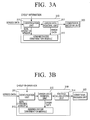
- FIG. 3A is a view illustrating an example of the spatial filtering unit of FIG. 2 .
- the spatial filtering unit 310 includes an identification unit 311, an error data removal unit 312, and an administrator confirmation module 313.
- the identification unit 311 analyzes the sensed data and identifies a sensor which has never transmitted sensed value. For this, the identification unit 311 receives sensed data transmitted from the sensors S1, S2, ..., Sm of each place L1, L2,..., Ln through the gateway G, and receives the sensor environment information including the group information from the sensor environment information storage unit 220.
- the sensed data include values sensed by the sensors S1, S2,..., Sm, place information of the sensors S1, S2,...Sm, time information regarding when the values are sensed, and group information of the group including the sensors S1, S2,...Sm.
- the identification unit 311 identifies the group to which the sensors S1, S2,..., Sm belong based on the group information of the sensor environment information, and identifies information regarding the sensors included in the identified group.
- the identification unit 311 compares the information about the sensor which outputs the sensed data (e.g., sensor ID) with the sensor information of the identified group, thereby identifying an operated sensor and a non-operated sensor. For example, if there are 4 sensors (A ⁇ D) which output sensed data but if 5 sensors (A ⁇ E) are already registered in the group corresponding to the sensors (A ⁇ D), the identification unit 311 identifies the sensor E as a non-operated sensor or a malfunctioning sensor. The identification unit 311 transmits the sensed data of the operated sensor to the error data removal unit 312 and transmits information of the non-operated sensor to the administrator confirmation module 313.
- sensor ID information about the sensor which outputs the sensed data
- the identification unit 311 identifies the sensor E as a non-operated sensor or a malfunctioning sensor.
- the identification unit 311 transmits the sensed data of the operated sensor to the error data removal unit 312 and transmits information of the non-operated sensor to the administrator confirmation module 313.
- the error data removal unit 312 removes error data from the sensed data of the operated sensor which are input from the identification unit 311, and outputs the data in which error does not occur to the conditional decision unit 320. For example, if the 4 sensors (A ⁇ D) sense temperature values of 19°C, 20°C, 21°C, and 40°C, respectively, the error data removal unit 312 determines that the sensor D malfunctions and transmits the sensed data output from the sensors (A ⁇ C) to the conditional decision unit 320.
- the error data removal unit 312 removes error data using the following algorithm:
- the error data removal unit 312 processes a sensed value having the largest difference between the sensed values in advance. For example, the error data removal unit 312 determines whether there is an error in the sensed value of 40°C since the sensed value of 40°C has the largest difference with respect to other temperature values.
- the sensed value having the largest difference is referred to as a target value.
- the error data removal unit 312 calculates a difference between the target value and an average of the other sensed values. That is, the error data removal unit 312 calculates the average of the sensed values, 19°C, 20°C, and 21°C, that is, 20°C, and calculates a difference between the values 20°C and 40°C.
- the error data removal unit 312 determines that the target value has an error if the calculated difference is above 50% of the average. For example, the difference 20°C is calculated between the target value 40°C and the average of the other sensed values 20°C. Since the difference 20°C is 100% of the average, the error data removal unit 312 determines that the sensor D which senses 40°C has an error or that there is an error only in the place where the sensor E is installed, and informs the administrator confirmation module 313 that error data of 40°C is sensed by the sensor D.
- the administrator confirmation module 313 stores information of the non-operated sensor and information of the sensor which outputs error data (e.g., identification information), and notifies the administrator of an alarming message.
- error data e.g., identification information
- the administrator confirms the non-operated sensor or the malfunctioning sensor through the alarming message and determines whether the sensor actually malfunctions.
- the administrator confirmation module 313 transmits the information of the sensor which is confirmed as having actually malfunctioned by the administrator, that is, the administrator confirmation information to the context-awareness information generation unit 341.
- the spatial filtering unit 310 may further include an average calculation unit 314 as shown in FIG. 3B .
- the average calculation unit 314 calculates an average of sensed data in which error input from the error data removal unit 312 does not occur, and outputs the calculated average to the conditional decision unit 320.
- the average calculation unit 314 may calculate an average of sensed values included in the sensed data.
- the spatial filtering unit 310 removes the sensor which has not transmitted sensed data and the sensor in which an error is generated, and outputs sensed data which is normally detected from the same group to the conditional decision unit 320.
- conditional decision unit 320 compares the sensed data which is filtered by the spatial filtering unit 310 with the condition information which is input from the condition information storage unit 240 to determine a current state of the place corresponding to the group.
- the conditional decision unit 320 outputs the determined current state, that is, the conditional decision information to the temporal decision unit 330.
- conditional decision unit 320 determines the current state using the condition information 1 of table 1.
- the decision result of the conditional decision unit 320 includes 'normal', 'warning', 'danger', and 'user-defined state'.
- the user-defined state is a current state set by the user or the administrator.
- FIG. 4 is a diagram illustrating the temporal decision unit of FIG. 2 in detail.
- the temporal decision unit 330 re-determines the current state which has been determined by the conditional decision unit 320 using past data accumulated in the DB 350, regulation generated from the past data, and filtered data. That is, the temporal decision unit 330 complements the determined current state using the past data.
- the past data is data which was sensed for a specific time in the past and includes sensed values, identification information of the sensor and group information of the sensor, and result of decision by sensed value (e.g., warning).
- the temporal decision unit 330 compares the current state, 'normal', determined by the conditional decision unit 320 with the regulation of the past data to re-determine the current state more specifically.
- the temporal decision unit 330 includes a regulation generation unit 331, a regulation storage unit 332, and a comparison decision unit 333.
- the regulation generation unit 331 generates regulation (a result caused by condition) based on the past data stored in the DB 350.
- the regulation generation unit 331 generates regulation (1) for the normal value of the past data, regulation (2) for the abnormal value of the past data, regulation (3) for a variation in the normal value of the past data, and regulation (4) for an upper limit and a lower limit of the past data, and stores the regulations to the regulation storage unit 332.
- the regulation (1) of the normal value of the past data prescribes that, if a currently sensed temperature is from 20°C to 30°C, a current state is determined to be normal since the temperature of 20°C to 30°C was determined to be normal for the past 3 years.
- the regulation (3) for the variation in the normal value of the past data prescribes that if temperature abruptly rises by above 50%, the current state is determined to be a warning since the abrupt rise in temperature by above 50% indicates presence of fire.
- the comparison decision unit 333 compares the filtered data input from the conditional decision unit 320 and the determined current state with the regulation stored in the regulation storage unit 332 to re-determine the current state, and generate a final decision result.
- the comparison decision unit 333 has the option of re-determining the current state, depending on the current state determined by the conditional decision unit 320.
- the comparison decision unit 333 additionally re-determines the current state to generate a final decision result such as 'normal', 'caution', 'attention', or a 'user-defined state'.
- the 'caution' and 'attention' is to classify a normal state more specifically, and indicate when a current state is determined to be abnormal compared to the past data, even if the current state seems normal.
- the comparison decision unit 333 perceives that the current state is an emergency state and transmits the state to the result processing unit 340 without conducting a further comparing process.
- the result processing unit 340 receives the current state which is determined to be 'danger' or 'warning' by the conditional decision unit 320 and which bypasses the temporal determination unit 330, and also receives the current state re-determined to be 'normal', 'caution', 'attention', or 'user-defined state' by the temporal determination unit 330.
- the comparison decision unit 333 determines that the current state is 'normal' if 'the normal' state determined by the conditional decision unit 320 is mapped with the regulation (1) of the regulation storage unit 332.
- the comparison decision unit 333 determines the current state to be 'caution', which is more dangerous than the normal state, if the 'normal' state determined by the conditional decision unit 320 has a variation compared the average data of the past data.
- the variation refers to a reference value which is pre-calculated to determine the current state.
- the comparison decision unit 333 determines the current state to be 'attention', which is more dangerous than the normal state, if the 'normal' state determined by the conditional decision unit 320 has an abrupt variation compared to the average data of the past data.
- the abrupt variation refers to a reference value which is pre-calculated to determine the current state.
- the comparison decision unit 333 determines that the current state is a 'user-defined state' which is defined by the user. For example, the user checks the current state which is determined to be 'user-defined state' and perceives that the current state is neither 'normal', 'warning', nor 'danger' and that it is difficult to determined the current state.
- FIG. 5 is a view illustrating the result processing unit of FIG. 2 .
- the result processing unit 340 of FIG. 5 combines the current state input from the temporal decision unit 330 and information regarding the group to generate a context-awareness result.
- the information regarding the group is known from the information included in the sensed data input to the spatial filtering unit 310. That is, the information regarding the group may be places, time information of the sensor which sense data (e.g., S1, S2,..., Sm) or identification information of the group to which the sensors S1, S2,..., Sm belong.
- the result processing unit 340 includes a context-awareness information generation unit 341, a sensing data markup language (SDML) schema providing unit 342, a control unit 343, an alarming unit 344, and a short message service (SMS) transmission unit 345.
- SDML sensing data markup language
- SMS short message service
- the context-awareness information generation unit 341 generates context-awareness information based on the SDML schema of the SDML schema providing unit 342, and transmits the generated context-awareness information to the control unit 343.
- the SDML schema has a structure shown in FIG. 6B .
- the block 'group' indicates information regarding each group to which the sensor belongs
- the block 'sensing' indicates information regarding each sensor
- the block 'errorConfirm' indicates information regarding the sensor in which an error is generated.
- the context-awareness information generation unit 341 receives the sensed data and the final decision result from the temporal decision unit 330 and receives the administrator confirmation information from the administrator confirmation module 313, and combines the sensed data, the final decision result, and the administrator confirmation information to generate context-awareness information. That is, the context-awareness information includes the final decision result input from the temporal decision unit 330.
- the context-awareness information generated based on the SDML is stored to the DB 350.
- the control unit 343 is adaptively operated according to the final decision result included in the context-awareness information. If the current state is determined to be 'normal', the control unit 343 does not perform extra operation, and if the current state is determined to be 'caution', 'attention', or a user-defined state, the control unit 343 requests the administrator, who should be reported preferentially, to check the current state since an error is detected from the sensors S1, S2,..., Sm through the SMS transmission unit 345.
- control unit 343 controls the alarming unit 344 to notify the emergency state of the place where the sensors S1, S2,..., Sm are installed to allow the administrator to take appropriate measures.
- the control unit 343 determines that there is a possibility of presence of fire and controls the SMS transmission unit 345 to transmit an alarming message to the administrator.
- the control unit 343 determines that fire occurs and informs a fire station and an administrator, who should be reported of the current state secondarily, of the emergency state. For example, the control unit 343 controls a sprinkler and a blower installed in the place to be operated, or controls the SMS transmission unit 345 to transmit a SMS to inform the fire station and the administrator of the emergency state or to ring an emergency bell to notify the emergency state.
- the data which is sensed by the sensors belonging to the same group is analyzed more specifically so that the context can be perceived more accurately.
- the present disclosure applies the spatial filtering, the conditional decision, and the temporal decision using the past data, thereby enabling accurate context-awareness.
- the context-awareness engine 300 intelligently analyzes the sensed data and provides a solution according to the result of analysis. Accordingly, in the ubiquitous society, monitoring systems such as environment monitoring system, agricultural product growth monitoring system, and army monitoring system can by intelligently controlled by the context-awareness system of the present disclosure without human intervention.
Landscapes
- Engineering & Computer Science (AREA)
- Computer Networks & Wireless Communication (AREA)
- Signal Processing (AREA)
- General Health & Medical Sciences (AREA)
- Health & Medical Sciences (AREA)
- Business, Economics & Management (AREA)
- Computing Systems (AREA)
- Medical Informatics (AREA)
- Primary Health Care (AREA)
- Strategic Management (AREA)
- Marine Sciences & Fisheries (AREA)
- Mining & Mineral Resources (AREA)
- Agronomy & Crop Science (AREA)
- Economics (AREA)
- Human Resources & Organizations (AREA)
- Marketing (AREA)
- Life Sciences & Earth Sciences (AREA)
- Animal Husbandry (AREA)
- Tourism & Hospitality (AREA)
- Physics & Mathematics (AREA)
- General Business, Economics & Management (AREA)
- General Physics & Mathematics (AREA)
- Theoretical Computer Science (AREA)
- Alarm Systems (AREA)
- Combined Controls Of Internal Combustion Engines (AREA)
- Arrangements For Transmission Of Measured Signals (AREA)
Applications Claiming Priority (1)
| Application Number | Priority Date | Filing Date | Title |
|---|---|---|---|
| KR1020080059535A KR100979783B1 (ko) | 2008-06-24 | 2008-06-24 | Wsn 기반 상황인지 엔진 |
Publications (3)
| Publication Number | Publication Date |
|---|---|
| EP2139200A2 true EP2139200A2 (de) | 2009-12-30 |
| EP2139200A8 EP2139200A8 (de) | 2010-03-24 |
| EP2139200A3 EP2139200A3 (de) | 2013-06-26 |
Family
ID=41128045
Family Applications (1)
| Application Number | Title | Priority Date | Filing Date |
|---|---|---|---|
| EP09163611.8A Withdrawn EP2139200A3 (de) | 2008-06-24 | 2009-06-24 | WSN-basierte kontextsensible Maschine |
Country Status (3)
| Country | Link |
|---|---|
| US (1) | US8145445B2 (de) |
| EP (1) | EP2139200A3 (de) |
| KR (1) | KR100979783B1 (de) |
Cited By (2)
| Publication number | Priority date | Publication date | Assignee | Title |
|---|---|---|---|---|
| EP2447722A1 (de) * | 2010-10-29 | 2012-05-02 | General Electric Company | Steuersystem und Verfahren zur Verifizierung des Betriebs mindestens eines Windturbinensensors |
| CN106972948A (zh) * | 2017-02-15 | 2017-07-21 | 广东技术师范学院 | 一种感知数据获取方法 |
Families Citing this family (10)
| Publication number | Priority date | Publication date | Assignee | Title |
|---|---|---|---|---|
| CN102394917A (zh) * | 2011-10-19 | 2012-03-28 | 上海海洋大学 | 一种海洋环境监测及预警系统 |
| KR101355455B1 (ko) * | 2012-03-22 | 2014-02-12 | (주)이지팜 | 유비쿼터스 센서 네트워크에서 센싱 정보 처리 장치 및 방법 |
| US9100360B2 (en) * | 2012-06-28 | 2015-08-04 | Cable Television Laboratories, Inc. | Contextual awareness architecture |
| KR101504182B1 (ko) * | 2013-02-26 | 2015-03-24 | 주식회사 케이티 | 소셜 미디어 연동을 기반으로 m2m 디바이스를 제어하는 방법 및 시스템 |
| US9467516B2 (en) * | 2013-07-01 | 2016-10-11 | Electronics And Telecommunications Research Institute | Method and apparatus for managing resource |
| CN103700240A (zh) * | 2013-12-20 | 2014-04-02 | 中国船舶重工集团公司第七一五研究所 | 一种适用于混浊浅水的水文测量信息无线传输系统及方法 |
| KR20160140185A (ko) * | 2015-05-29 | 2016-12-07 | 삼성전자주식회사 | 통신 서비스를 수행하는 방법 및 이를 위한 장치 |
| CN109218049B (zh) * | 2017-06-30 | 2021-10-26 | 华为技术有限公司 | 一种控制方法、相关设备以及系统 |
| KR102185357B1 (ko) * | 2019-12-13 | 2020-12-02 | 주식회사 이에스피 | 위치기반 광산 갱내 환경상태 측정시스템 및 그 방법 |
| US20210405632A1 (en) * | 2021-09-09 | 2021-12-30 | Intel Corporation | Technology to cluster multiple sensors towards a self-moderating and self-healing performance for autonomous systems |
Family Cites Families (7)
| Publication number | Priority date | Publication date | Assignee | Title |
|---|---|---|---|---|
| KR100682995B1 (ko) * | 2004-12-16 | 2007-02-15 | 한국전자통신연구원 | 유비쿼터스 기반의 상황 정보 제공 서비스 시스템 및 그방법 |
| KR100718094B1 (ko) * | 2005-09-21 | 2007-05-16 | 삼성전자주식회사 | 무선 센서 네트워크에서의 이상 데이터 처리 방법 |
| JP2007272399A (ja) | 2006-03-30 | 2007-10-18 | Oki Electric Ind Co Ltd | サービス提供システム |
| KR100800616B1 (ko) * | 2006-06-27 | 2008-02-11 | 주식회사 롯데기공 | 지그비를 이용한 모니터링 시스템 |
| KR100821561B1 (ko) * | 2006-11-17 | 2008-04-15 | 한국전자통신연구원 | 유비쿼터스 센서 네트워크를 이용한 소음 및 진동 관리방법 및 시스템 |
| KR100835174B1 (ko) * | 2006-12-08 | 2008-06-05 | 한국전자통신연구원 | 페어 노드를 갖는 무선 센서 네트워크에서의 센싱 정보전송 방법 |
| KR20090064937A (ko) * | 2007-12-17 | 2009-06-22 | 한국전자통신연구원 | 상황 인지 시스템 및 그 시스템에서의 상황 인지 방법 |
-
2008
- 2008-06-24 KR KR1020080059535A patent/KR100979783B1/ko not_active Expired - Fee Related
-
2009
- 2009-06-24 EP EP09163611.8A patent/EP2139200A3/de not_active Withdrawn
- 2009-06-24 US US12/490,645 patent/US8145445B2/en not_active Expired - Fee Related
Cited By (4)
| Publication number | Priority date | Publication date | Assignee | Title |
|---|---|---|---|---|
| EP2447722A1 (de) * | 2010-10-29 | 2012-05-02 | General Electric Company | Steuersystem und Verfahren zur Verifizierung des Betriebs mindestens eines Windturbinensensors |
| CN102454546A (zh) * | 2010-10-29 | 2012-05-16 | 通用电气公司 | 检验至少一个风力涡轮机传感器的运行的控制系统和方法 |
| CN106972948A (zh) * | 2017-02-15 | 2017-07-21 | 广东技术师范学院 | 一种感知数据获取方法 |
| CN106972948B (zh) * | 2017-02-15 | 2020-05-05 | 广东技术师范大学 | 一种感知数据获取方法 |
Also Published As
| Publication number | Publication date |
|---|---|
| US8145445B2 (en) | 2012-03-27 |
| EP2139200A3 (de) | 2013-06-26 |
| EP2139200A8 (de) | 2010-03-24 |
| KR100979783B1 (ko) | 2010-09-03 |
| US20090316594A1 (en) | 2009-12-24 |
| KR20100000151A (ko) | 2010-01-06 |
Similar Documents
| Publication | Publication Date | Title |
|---|---|---|
| EP2139200A2 (de) | WSN-basierte kontextsensible Maschine | |
| EP3059719B1 (de) | Cloud-basiertes alarmsystem mit alarmüberwachung und -meldung | |
| CN103716480B (zh) | 视频监控系统告警身份确认方法、装置及系统 | |
| CN111432087A (zh) | 一种告警方法以及相关设备 | |
| CA3052352A1 (en) | Bridge device supporting alarm format | |
| KR102166709B1 (ko) | 데이터 기반 관제 시스템 및 그 방법 | |
| CN112797583A (zh) | 空调器及其控制方法、存储介质、控制装置 | |
| US20070139188A1 (en) | Method and apparatus for communicating between a home network and a wireless network | |
| CN110967566A (zh) | 电器故障检测方法及装置 | |
| JP2006146827A5 (de) | ||
| CN112165518B (zh) | 一种安全监控策略生成方法、装置 | |
| KR101409299B1 (ko) | 셀프 콜 기능을 갖는 게이트 웨이를 이용한 독거노인 원격 모니터링 시스템 및 방법 | |
| CN112185059B (zh) | 一种提醒用户的方法、装置 | |
| CN107483550B (zh) | 一种基于物联网的监控方法及物联网服务器 | |
| US8977514B2 (en) | Thermal activity detection and response | |
| EP3401888B1 (de) | Verfahren und system zur validierung einer alarmsituation | |
| KR101464973B1 (ko) | 보험사 연계형 블랙박스를 이용한 교통사고 처리 시스템 | |
| CN117073149A (zh) | 空调器关联的安全防护控制方法及装置 | |
| KR20190079012A (ko) | 스마트 미러를 이용한 농장 관리 시스템 | |
| CN112165707A (zh) | 一种信标发送方法、装置 | |
| KR20150146337A (ko) | 셀프 콜 기능을 갖는 게이트 웨이를 이용한 독거노인 원격 모니터링 시스템 및 방법 | |
| KR101828813B1 (ko) | 온도 및 습도 정보에 기초하여 다중 전송을 수행하는 전관방송시스템 및 그 방법 | |
| CN112135335B (zh) | 一种接入网络的方法、装置 | |
| CN112135296B (zh) | 一种基于改进的信标帧的安全监控的方法、装置 | |
| CN118900208B (zh) | 一种基于多终端交互的智能家居控制系统及方法 |
Legal Events
| Date | Code | Title | Description |
|---|---|---|---|
| PUAI | Public reference made under article 153(3) epc to a published international application that has entered the european phase |
Free format text: ORIGINAL CODE: 0009012 |
|
| 17P | Request for examination filed |
Effective date: 20090624 |
|
| AK | Designated contracting states |
Kind code of ref document: A2 Designated state(s): AT BE BG CH CY CZ DE DK EE ES FI FR GB GR HR HU IE IS IT LI LT LU LV MC MK MT NL NO PL PT RO SE SI SK TR |
|
| RAP1 | Party data changed (applicant data changed or rights of an application transferred) |
Owner name: METARIGHTS, LTD. |
|
| PUAL | Search report despatched |
Free format text: ORIGINAL CODE: 0009013 |
|
| AK | Designated contracting states |
Kind code of ref document: A3 Designated state(s): AT BE BG CH CY CZ DE DK EE ES FI FR GB GR HR HU IE IS IT LI LT LU LV MC MK MT NL NO PL PT RO SE SI SK TR |
|
| AX | Request for extension of the european patent |
Extension state: AL BA RS |
|
| RIC1 | Information provided on ipc code assigned before grant |
Ipc: H04L 29/06 20060101AFI20130521BHEP |
|
| STAA | Information on the status of an ep patent application or granted ep patent |
Free format text: STATUS: THE APPLICATION IS DEEMED TO BE WITHDRAWN |
|
| 18D | Application deemed to be withdrawn |
Effective date: 20140103 |