EP2139046A1 - Module photovoltaïque - Google Patents
Module photovoltaïque Download PDFInfo
- Publication number
- EP2139046A1 EP2139046A1 EP07834946A EP07834946A EP2139046A1 EP 2139046 A1 EP2139046 A1 EP 2139046A1 EP 07834946 A EP07834946 A EP 07834946A EP 07834946 A EP07834946 A EP 07834946A EP 2139046 A1 EP2139046 A1 EP 2139046A1
- Authority
- EP
- European Patent Office
- Prior art keywords
- module according
- photoelectric module
- optical elements
- photoelectric
- side walls
- Prior art date
- Legal status (The legal status is an assumption and is not a legal conclusion. Google has not performed a legal analysis and makes no representation as to the accuracy of the status listed.)
- Withdrawn
Links
- 230000003287 optical effect Effects 0.000 claims abstract description 52
- 229920001296 polysiloxane Polymers 0.000 claims abstract description 8
- 230000000712 assembly Effects 0.000 claims abstract description 7
- 238000000429 assembly Methods 0.000 claims abstract description 7
- 238000007789 sealing Methods 0.000 claims abstract description 3
- 238000000926 separation method Methods 0.000 claims abstract description 3
- 239000011521 glass Substances 0.000 claims description 20
- 229910052751 metal Inorganic materials 0.000 claims description 18
- 239000002184 metal Substances 0.000 claims description 18
- 230000001681 protective effect Effects 0.000 claims description 15
- 239000005368 silicate glass Substances 0.000 claims description 10
- 229910001335 Galvanized steel Inorganic materials 0.000 claims description 9
- 239000008397 galvanized steel Substances 0.000 claims description 9
- 238000000576 coating method Methods 0.000 claims description 8
- 239000011248 coating agent Substances 0.000 claims description 7
- 239000006223 plastic coating Substances 0.000 claims description 6
- 239000000463 material Substances 0.000 claims description 5
- 229910000838 Al alloy Inorganic materials 0.000 claims description 3
- 229910000831 Steel Inorganic materials 0.000 claims description 3
- 229910052782 aluminium Inorganic materials 0.000 claims description 3
- XAGFODPZIPBFFR-UHFFFAOYSA-N aluminium Chemical compound [Al] XAGFODPZIPBFFR-UHFFFAOYSA-N 0.000 claims description 3
- 210000003298 dental enamel Anatomy 0.000 claims description 3
- 239000010959 steel Substances 0.000 claims description 3
- VYPSYNLAJGMNEJ-UHFFFAOYSA-N Silicium dioxide Chemical compound O=[Si]=O VYPSYNLAJGMNEJ-UHFFFAOYSA-N 0.000 abstract 1
- 238000004519 manufacturing process Methods 0.000 description 11
- 230000007613 environmental effect Effects 0.000 description 10
- 230000005855 radiation Effects 0.000 description 8
- 238000006731 degradation reaction Methods 0.000 description 6
- 230000002411 adverse Effects 0.000 description 5
- 238000010276 construction Methods 0.000 description 5
- 238000009413 insulation Methods 0.000 description 4
- 230000000694 effects Effects 0.000 description 3
- 238000003384 imaging method Methods 0.000 description 3
- 239000000203 mixture Substances 0.000 description 3
- 239000004065 semiconductor Substances 0.000 description 3
- 239000000758 substrate Substances 0.000 description 3
- 239000000853 adhesive Substances 0.000 description 2
- 230000001070 adhesive effect Effects 0.000 description 2
- 230000015556 catabolic process Effects 0.000 description 2
- 238000006243 chemical reaction Methods 0.000 description 2
- 150000001875 compounds Chemical class 0.000 description 2
- 239000012141 concentrate Substances 0.000 description 2
- 238000010292 electrical insulation Methods 0.000 description 2
- 238000010438 heat treatment Methods 0.000 description 2
- 230000007774 longterm Effects 0.000 description 2
- 238000000034 method Methods 0.000 description 2
- 239000011253 protective coating Substances 0.000 description 2
- 229910000679 solder Inorganic materials 0.000 description 2
- GLGNXYJARSMNGJ-VKTIVEEGSA-N (1s,2s,3r,4r)-3-[[5-chloro-2-[(1-ethyl-6-methoxy-2-oxo-4,5-dihydro-3h-1-benzazepin-7-yl)amino]pyrimidin-4-yl]amino]bicyclo[2.2.1]hept-5-ene-2-carboxamide Chemical compound CCN1C(=O)CCCC2=C(OC)C(NC=3N=C(C(=CN=3)Cl)N[C@H]3[C@H]([C@@]4([H])C[C@@]3(C=C4)[H])C(N)=O)=CC=C21 GLGNXYJARSMNGJ-VKTIVEEGSA-N 0.000 description 1
- 238000010521 absorption reaction Methods 0.000 description 1
- 229940125758 compound 15 Drugs 0.000 description 1
- 239000004020 conductor Substances 0.000 description 1
- 230000006866 deterioration Effects 0.000 description 1
- 239000000428 dust Substances 0.000 description 1
- 238000004146 energy storage Methods 0.000 description 1
- 238000011156 evaluation Methods 0.000 description 1
- 239000004744 fabric Substances 0.000 description 1
- 238000003306 harvesting Methods 0.000 description 1
- 238000002955 isolation Methods 0.000 description 1
- 239000000615 nonconductor Substances 0.000 description 1
Images
Classifications
-
- H—ELECTRICITY
- H01—ELECTRIC ELEMENTS
- H01L—SEMICONDUCTOR DEVICES NOT COVERED BY CLASS H10
- H01L31/00—Semiconductor devices sensitive to infrared radiation, light, electromagnetic radiation of shorter wavelength or corpuscular radiation and specially adapted either for the conversion of the energy of such radiation into electrical energy or for the control of electrical energy by such radiation; Processes or apparatus specially adapted for the manufacture or treatment thereof or of parts thereof; Details thereof
- H01L31/04—Semiconductor devices sensitive to infrared radiation, light, electromagnetic radiation of shorter wavelength or corpuscular radiation and specially adapted either for the conversion of the energy of such radiation into electrical energy or for the control of electrical energy by such radiation; Processes or apparatus specially adapted for the manufacture or treatment thereof or of parts thereof; Details thereof adapted as photovoltaic [PV] conversion devices
- H01L31/052—Cooling means directly associated or integrated with the PV cell, e.g. integrated Peltier elements for active cooling or heat sinks directly associated with the PV cells
-
- H—ELECTRICITY
- H01—ELECTRIC ELEMENTS
- H01L—SEMICONDUCTOR DEVICES NOT COVERED BY CLASS H10
- H01L31/00—Semiconductor devices sensitive to infrared radiation, light, electromagnetic radiation of shorter wavelength or corpuscular radiation and specially adapted either for the conversion of the energy of such radiation into electrical energy or for the control of electrical energy by such radiation; Processes or apparatus specially adapted for the manufacture or treatment thereof or of parts thereof; Details thereof
- H01L31/04—Semiconductor devices sensitive to infrared radiation, light, electromagnetic radiation of shorter wavelength or corpuscular radiation and specially adapted either for the conversion of the energy of such radiation into electrical energy or for the control of electrical energy by such radiation; Processes or apparatus specially adapted for the manufacture or treatment thereof or of parts thereof; Details thereof adapted as photovoltaic [PV] conversion devices
- H01L31/042—PV modules or arrays of single PV cells
- H01L31/048—Encapsulation of modules
- H01L31/049—Protective back sheets
-
- H—ELECTRICITY
- H01—ELECTRIC ELEMENTS
- H01L—SEMICONDUCTOR DEVICES NOT COVERED BY CLASS H10
- H01L31/00—Semiconductor devices sensitive to infrared radiation, light, electromagnetic radiation of shorter wavelength or corpuscular radiation and specially adapted either for the conversion of the energy of such radiation into electrical energy or for the control of electrical energy by such radiation; Processes or apparatus specially adapted for the manufacture or treatment thereof or of parts thereof; Details thereof
- H01L31/04—Semiconductor devices sensitive to infrared radiation, light, electromagnetic radiation of shorter wavelength or corpuscular radiation and specially adapted either for the conversion of the energy of such radiation into electrical energy or for the control of electrical energy by such radiation; Processes or apparatus specially adapted for the manufacture or treatment thereof or of parts thereof; Details thereof adapted as photovoltaic [PV] conversion devices
- H01L31/054—Optical elements directly associated or integrated with the PV cell, e.g. light-reflecting means or light-concentrating means
- H01L31/0543—Optical elements directly associated or integrated with the PV cell, e.g. light-reflecting means or light-concentrating means comprising light concentrating means of the refractive type, e.g. lenses
-
- H—ELECTRICITY
- H01—ELECTRIC ELEMENTS
- H01L—SEMICONDUCTOR DEVICES NOT COVERED BY CLASS H10
- H01L31/00—Semiconductor devices sensitive to infrared radiation, light, electromagnetic radiation of shorter wavelength or corpuscular radiation and specially adapted either for the conversion of the energy of such radiation into electrical energy or for the control of electrical energy by such radiation; Processes or apparatus specially adapted for the manufacture or treatment thereof or of parts thereof; Details thereof
- H01L31/04—Semiconductor devices sensitive to infrared radiation, light, electromagnetic radiation of shorter wavelength or corpuscular radiation and specially adapted either for the conversion of the energy of such radiation into electrical energy or for the control of electrical energy by such radiation; Processes or apparatus specially adapted for the manufacture or treatment thereof or of parts thereof; Details thereof adapted as photovoltaic [PV] conversion devices
- H01L31/054—Optical elements directly associated or integrated with the PV cell, e.g. light-reflecting means or light-concentrating means
- H01L31/0547—Optical elements directly associated or integrated with the PV cell, e.g. light-reflecting means or light-concentrating means comprising light concentrating means of the reflecting type, e.g. parabolic mirrors, concentrators using total internal reflection
-
- Y—GENERAL TAGGING OF NEW TECHNOLOGICAL DEVELOPMENTS; GENERAL TAGGING OF CROSS-SECTIONAL TECHNOLOGIES SPANNING OVER SEVERAL SECTIONS OF THE IPC; TECHNICAL SUBJECTS COVERED BY FORMER USPC CROSS-REFERENCE ART COLLECTIONS [XRACs] AND DIGESTS
- Y02—TECHNOLOGIES OR APPLICATIONS FOR MITIGATION OR ADAPTATION AGAINST CLIMATE CHANGE
- Y02E—REDUCTION OF GREENHOUSE GAS [GHG] EMISSIONS, RELATED TO ENERGY GENERATION, TRANSMISSION OR DISTRIBUTION
- Y02E10/00—Energy generation through renewable energy sources
- Y02E10/50—Photovoltaic [PV] energy
- Y02E10/52—PV systems with concentrators
Definitions
- the invention relates to a photoelectric module according to the preamble of claim 1.
- the invention relates to the field of solar energy and more particularly to the photoelectric energy harvesting modules.
- the present invention is intended for use in solar cell collection plants (photovoltaic collection plants), which can be used as autonomous power supply systems and feed systems in different climatic regions.
- the absorption of the concentrated radiation consumes part of it for the heating of the cell. Therefore, the heat from the semiconductor structure must be efficiently dissipated because the unnecessary heating of the cell substantially affects its energy conversion characteristics as well as its lifetime and the output characteristic of the photoelectric module.
- the known photoelectric module with solar radiation collectors has side walls made of silicate glass. At the upper edges of the side walls, a front panel made of silicate glass is attached with Fresnel lenses. At the lower edges a back plate made of silicate glass with solar cells and heat-dissipating documents is attached ( "CONFERENCE RECORD OF THE TWENTY-EIGHT IEEE PHOTOVOLTAIC SPECIALISTS CONFERENCE-2000", Anhorage, Alaska, USA, 2000, p. 1169-1172 ).
- the Fresnel lenses are made of silicone. They are square and close together. They are firmly connected to the glass inner surface. The glass inner surface has a protective and carrier function. Each Fresnel lens is associated with its own solar cell. The solar cells are attached to the heat-dissipating metal backing. The heat dissipating documents are on the front glass surface of the back plate in such a way that the light-receiving surface of the photocell in the focus (focal spot) of the respective Fresnel lens is located.
- the heat dissipating metal backing is also one of the electrical contacts of the solar cell.
- the second contact is the upper metal coating of the metal-clad glass hard tissue, which is attached to the heat dissipating documents.
- a wire contact is created.
- the other end of the wire contact is connected to the contact network of the photocell.
- the solar cells are connected by contacts which are fastened to the metal base and to the upper metal covering of the glass fabric.
- the Fresnel lenses normally aligned with the sun's rays concentrate the sunlight and direct it to the light receiving surfaces of the solar cells.
- the solar cells convert the energy of the light quanta into electrical energy. In this case, a potential difference is formed at their contacts.
- the electrical energy generated by the module is forwarded to an external consumer or to an energy store.
- the heat dissipated by the solar cells is distributed through the heat dissipating metal substrates, transferred to the glass of the back plate and then released to the environment.
- this module has an insufficiently high concentration number and an insufficient width of the depuration characteristic. This reduces his energy output.
- the known photoelectric module lacks an individual sealed insulation of each individual solar cell. This substantially increases the likelihood of the occurrence of degradation processes in characteristics of all the solar cells of the photoelectric module as a result of falling below or exceeding the characteristics of gas medium, where all the solar cells of the module are arranged. As a result, a serious degradation of the module characteristics can occur up to a complete failure of the module.
- a photoelectric module which has a front panel of silicate glass with lens concentrators made of silicone, side walls and a back plate.
- the lens concentrators are located at the back of the front panel.
- the solar cells and coaxially arranged therewith additional optical elements are constructed on the top of the back plate, namely on the heat dissipating documents.
- the lens concentrators normal to the sun's rays focus the sunlight by directing it onto the light-receiving surfaces of the solar cells.
- the photocells convert the light quantum energy into electrical energy by forming a potential difference at their contacts.
- the electrical energy generated by the module is forwarded to an external consumer or an energy storage.
- the heat dissipated by the solar cells is distributed over the heat dissipating metal substrates, transferred to the glass of the back plate and then discharged into the environment.
- This photoelectric module exceeds its characteristics according to all other known photoelectric modules with concentrators, including the above-considered comparison product.
- the photoelectric module has a silicate glass front panel, side walls and a back plate. On the back of the front panel lens concentrators are made of silicone. On heat dissipating documents on the upper side of the rear plate solar cells and the coaxially arranged additional optical elements are constructed. According to the invention, the additional optical elements are part of the control modules of the solar cells.
- the assemblies mentioned are designed so that an individual seal of each solar cell and its separation is ensured by the inner module circumference.
- the lens concentrators may be formed as Fresnel lenses.
- the lens concentrators can be designed as plano-convex lenses.
- Additional optical elements may be formed as plano-convex lenses.
- Additional optical elements may be formed as metal focons (imaging cones) with protective glass cover.
- Additional optical elements may be implemented as total internal reflection foci.
- Additional optical elements may be formed as Fokone with total internal reflection and made of plastic.
- Focal total internal plastic reflectors can be visually connected to a glass protective cover from above.
- the outer surface of the protective glass cover may be coated with a reflection protection coating.
- the joints between the front panel, the side walls and the rear panel are made airtight.
- the side walls and / or the back plate may include one or more flexible inserts.
- the flexible inserts are formed as a bellows.
- the flexible inserts are made of a rubber-like material.
- the inner periphery of the photoelectric module may be hermetically connected to a device which ensures pressure equalization inside and outside the module.
- the front surface of the front panel can be coated with a reflection protection coating.
- the surfaces of the secondary optical elements which are formed as plano-convex lenses, may be coated with reflection protective coatings.
- the back plate may be made of metal, which is provided with a heat-conducting Elektroisolier für.
- the back plate can be made of galvanized steel with a plastic coating.
- the back plate is made of enamel steel.
- the back plate is made of glass.
- the side walls are made of aluminum or aluminum alloy.
- the side walls are made of galvanized steel.
- the side walls are made of galvanized steel with a plastic coating.
- the side walls are made of plastic.
- the additional optical elements in the form of plano-convex lenses are made of silicate glass.
- the side walls are at an angle of 0 ⁇ a ⁇ arctan R - W 2 ⁇ H arranged to the normal to the front panel level, it is R - the distance between the optical axes of the adjacent Fresnel lenses, W - the width of the heat dissipating pad, H - the distance between the front and rear plates.
- Each solar cell has its own small sealed circumference with a controllable composition of the protective gas during manufacture. Failure to comply with the composition of said protective gas is unlikely. Nevertheless, should the mentioned error in the composition of the protective gas, it only leads to a deterioration of the characteristics of only this affected solar cell. Since the module consists of tens or hundreds of solar cells, such an error can have practically no effect on the output characteristic of the entire module.
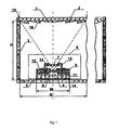
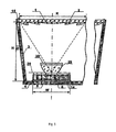
- control assembly 8 of the solar cells ensures sealing of each of the solar cells 6 from the inner circumference of the module during the preliminary stage of the process-related manufacturing process of the photoelectric modules. This makes it possible to sort out the potentially unreliable solar cells in advance. This also ensures increased resistance of the photoelectric modules to the influence of all unfavorable environmental factors both in the manufacture of the modules and during their operation.
- the control module 8 of the solar cells can be designed in the form of rails 9 constructed in a gastight manner on the heat dissipating supports 5.
- the rails 9 are made of non-conductor material with current-conducting metallized layers 10 and 11 on both sides.
- a metal flange 12 is airtight with the coaxial to the solar cell 6 arranged additional optical element 7 constructed.
- the additional optical element 7 is airtight connected to the flange 12.
- the upper contact of the solar cell 6 is electrically coupled by means of a conductor 13 with the upper current-conducting layer 10 of the rail 9 ( Fig. 1 ).
- the heat dissipating pad 5 is placed on the back plate 4 by means of a thin compound layer 14.
- the solar cells 6 may be soldered to the heat dissipating pad 5, for example, with solder.
- the front panel 1 is airtight by means of a compound 15 with the side walls 3 assembled.
- the lens concentrators 2 are designed as Fresnel lenses 16 or in the form of plano-convex lenses 17 ( Fig. 2 ).
- the Fresnel lenses 16 are made of silicone and have a square shape. They are arranged close to each other and firmly connected to the rear surface of the front panel 1. Each Fresnel lens 16 is associated with its own solar cell 6. The heat dissipating pads 5 are located on the front side of the rear plate 4 in such a way that the light-receiving surface of the solar cell 6 is located in the optical line of the corresponding Fresnel lens 16.
- the plano-convex lenses 17 are made of silicone and have a square shape. They are arranged close to each other and firmly connected to the rear surface of the front panel 1. Each lens 17 corresponds to a separate solar cell 6.
- the heat dissipating documents 5 are located on the front side of the back plate 4 in such a way that the light-receiving surface of the solar cell 6 is in the optical line of the corresponding Fresnel lens 17.
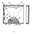
- a photoelectric module is shown with additional optical elements 7, which are formed in the form of plano-convex lenses 18.
- the flange 19 is airtight attached to the heat dissipating pad 5, for example, soldered or glued.
- This lens 18 is glued tightly on the flange airtight.
- the flange 19 has a sealed electrical input 20, which is connected to the upper contact of the solar cell 6.
- the side wall 3 has an insert in the form of a bellows 21.
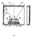
- Fig. 3 shows a photoelectric module with additional optical elements 7, which are formed as Metallfokone (imaging cones) 22.
- a metal flange 23 is provided with an inner hole in the form of an optical focus 22.
- the Fokon 22 is airtight on the heat dissipating pad 5, for example, attached or bonded with soft solder.
- a protective cover 24 made of glass is hermetically attached to the flange 23 with adhesive.
- the flange 23 has a sealed electrical outlet 20, which is connected to the upper contact of the solar cell 6.
- the side wall 3 has a flexible insert 25.
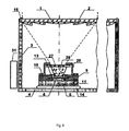
- Fig. 4 shows a photoelectric module with additional optical elements 7 in the form of a Fokun 26 with total internal reflection.
- the focal point 26 is formed on the inner surface of a protective cover 27 and has optical contact with the photoactive surface of the solar cell 6.
- the protective cover 27 made of glass is airtightly mounted on the flange 28 by means of an adhesive.
- the Fokon 26 may be formed of plastic.
- the inner circumference of the photoelectric module is airtight connected to a device 31, which ensures a pressure equalization inside and outside the module.
- a photoelectric module is shown with additional optical elements 7, which are formed in the form of a Fokun 29 with total internal reflection.
- the focal point 29 is arranged on the photoactive surface of the solar cell 6.
- the optical compound used for the production of such a focus simultaneously represents a protection of the solar cell 6 from environmental influences.
- the focal point 29 is provided at the top with a protective cover 30 made of glass.
- the outer surface of the protective cover 30 may be coated with a reflection-proof coating to reduce optical losses.
- the Fokon 29 may be made of plastic.
- the Fig. 4 and 5 include embodiments of this invention with focuses that utilize an effect of total internal reflection at the interface between two optical media having different refractive indices.
- the sidewalls 3 and / or the backplate 4 may include one or more flexible inserts 25 to balance the mechanical stresses of the module construction during a pressure change inside and outside the module.
- the flexible inserts 25 may be in the form of a bellows 21.
- the flexible inserts 25 may be made of a rubber-like material.
- the inner periphery of the photoelectric module may be hermetically connected to a device 31 which ensures pressure equalization inside and outside the module.
- the outer surface of the front panel 1 may be coated with a reflection-proof coating to reduce the optical losses.
- Both surfaces of the additional optical elements in the form of plano-convex lenses 18 may be coated with reflection protective coatings in order to reduce the optical losses.
- the back plate 4 is made of metal with a heat-conducting electrical insulating layer to ensure the electrical insulation of the solar cells from the rear metal plate of the module.
- the back plate 4 is made of galvanized steel with a plastic coating to ensure the module's resistance to adverse environmental factors.
- the backplate 4 is made of enamel steel to increase the module's resistance to adverse environmental factors and to insure the electrical isolation of the solar cells from the metal backplate of the module.
- the backplate 4 is made of glass to increase the module's resistance to adverse environmental factors and to insure the electrical insulation of the solar cells from the metal backplate of the module.
- the side walls 3 are made of aluminum or an aluminum alloy to keep the weight of the module low.
- the side walls 3 are made of galvanized steel to increase the module's resistance to adverse environmental factors.
- the side walls 3 are made of galvanized steel with a plastic coating to further increase the module's resistance to adverse environmental factors.
- the side walls 3 are made of plastic to reduce the weight of the module and to increase the resistance of the module to unfavorable environmental factors.
- the additional optical elements 7 in the form of plano-convex lenses 18 are made of silicate glass in order to reduce the optical losses.
- the side walls 3 are at an angle of 0 ⁇ a ⁇ arctan R - W 2 ⁇ H arranged to the normal to the front panel 1 level, is R - the distance between the optical axes of the adjacent Fresnel lenses, W - the width of the heat dissipating pad 5, H - the distance between the front 1 and rear plate 4 to reduce the overall size of the module and to increase and improve the manufacturing accuracy and assembly of the module housing.
- control assembly 8 ensures a gas-tight insulation of each solar cell 6 from the inner periphery of the module in the preliminary stage of the procedural manufacturing process of the photoelectric collecting modules. This makes it possible to sort out the potentially unreliable solar cells in advance and to ensure an increased resistance of the photoelectric modules to the influence of the entirety of the unfavorable environmental factors both in the production of the modules and during their operation.
- the lens concentrators 2 (for example Fresnel lenses 16) oriented normal to the sun rays concentrate the sunlight and direct it to the additional optical elements 7, 18, 24, 27 or 30.
- the optical elements 7, 18, 24, 27 or 30 are components of control modules 8 of the solar cells.
- the solar cells are designed so that the individual sealable insulation of each solar cell 6 is ensured by the inner circumference of the module.
- the lens concentrators 2 focus the light on the light-receiving surfaces of the solar cells 6.
- additional optical elements 7 allows the ratio of the sunlight concentration increase several times and at the same time increase the range of permissible disorientation of the module in the solar direction.
- control assemblies 8 of the solar cells 6, which can be individually sealed and insulated from the inner circumference of the module, makes it possible to apply automated production processes during their production and to carry out the sorting out of the control assemblies 8 of the solar cells before the photoelectric modules are assembled.
- the solar cells 6 convert the light quantum energy into electrical energy by forming a potential difference at their contacts.
- the electrical energy generated by the module is forwarded to an external consumer or to an energy store.
- the heat dissipated by the solar cells 6 is distributed over the heat dissipating metal substrates 5, transferred to the rear plate 4 and then released by own radiation and free convection to the environment.
- the application of the proposed photoelectric module results in a considerable efficiency. This is because the registered photoelectric module is structurally simple in construction, has high photoelectric and strength characteristics, ensuring reliable, safe and long-term operation.
- the module is high-tech-equitable in its production and has a high energy output as well as high economic key figures.
Landscapes
- Physics & Mathematics (AREA)
- Condensed Matter Physics & Semiconductors (AREA)
- Electromagnetism (AREA)
- General Physics & Mathematics (AREA)
- Engineering & Computer Science (AREA)
- Computer Hardware Design (AREA)
- Microelectronics & Electronic Packaging (AREA)
- Power Engineering (AREA)
- Photovoltaic Devices (AREA)
Applications Claiming Priority (1)
| Application Number | Priority Date | Filing Date | Title |
|---|---|---|---|
| PCT/RU2007/000197 WO2008127142A1 (fr) | 2007-04-16 | 2007-04-16 | Module photovoltaïque |
Publications (2)
| Publication Number | Publication Date |
|---|---|
| EP2139046A1 true EP2139046A1 (fr) | 2009-12-30 |
| EP2139046A4 EP2139046A4 (fr) | 2014-09-24 |
Family
ID=39864145
Family Applications (1)
| Application Number | Title | Priority Date | Filing Date |
|---|---|---|---|
| EP07834946.1A Withdrawn EP2139046A4 (fr) | 2007-04-16 | 2007-04-16 | Module photovoltaïque |
Country Status (2)
| Country | Link |
|---|---|
| EP (1) | EP2139046A4 (fr) |
| WO (1) | WO2008127142A1 (fr) |
Cited By (10)
| Publication number | Priority date | Publication date | Assignee | Title |
|---|---|---|---|---|
| DE102009023366A1 (de) * | 2009-05-29 | 2010-12-02 | Leifheit Ag | Waage mit Energiewandler |
| CN102231400A (zh) * | 2011-07-06 | 2011-11-02 | 张睿丰 | 太阳能聚光光伏发电电池组件以及聚光光伏发电模组 |
| CN103697866A (zh) * | 2013-12-09 | 2014-04-02 | 长江勘测规划设计研究有限责任公司 | 野外测量同轴保护装置及其扳手 |
| CN104022732A (zh) * | 2014-06-19 | 2014-09-03 | 成都聚合科技有限公司 | 一种聚光太阳能透镜 |
| CN104038149A (zh) * | 2014-06-19 | 2014-09-10 | 成都聚合科技有限公司 | 一种聚光太阳能透镜模块 |
| NL2010592C2 (nl) * | 2013-04-09 | 2014-10-13 | Suncycle B V | Halfgeleiderinrichting. |
| NL2010591C2 (nl) * | 2013-04-09 | 2014-10-13 | Suncycle B V | Foto-voltaã¯sche inrichting. |
| CN104320069A (zh) * | 2014-10-29 | 2015-01-28 | 成都聚合科技有限公司 | 一种聚光太阳能透镜固定条 |
| CN104320070A (zh) * | 2014-10-29 | 2015-01-28 | 成都聚合科技有限公司 | 一种聚光光伏透镜固定杆 |
| FR3029038A1 (fr) * | 2014-11-26 | 2016-05-27 | Commissariat Energie Atomique | Procede de fabrication d'un concentrateur photovoltaique a structure optique munie d'un double etages de lentilles optiques |
Families Citing this family (13)
| Publication number | Priority date | Publication date | Assignee | Title |
|---|---|---|---|---|
| WO2010137687A1 (fr) * | 2009-05-28 | 2010-12-02 | 京セラ株式会社 | Composant pour dispositif de conversion photoélectrique, dispositif de conversion photoélectrique et module de conversion photoélectrique |
| EP2278631A1 (fr) * | 2009-07-20 | 2011-01-26 | Fraunhofer-Gesellschaft zur Förderung der angewandten Forschung e.V. | Bloc de cellules solaires et agencement de cellules solaires |
| JP5388791B2 (ja) * | 2009-10-21 | 2014-01-15 | 京セラ株式会社 | 光電変換装置、並びに光電変換モジュール |
| JP5441617B2 (ja) * | 2009-10-30 | 2014-03-12 | 京セラ株式会社 | 光電変換装置及び光電変換モジュール |
| JP5388754B2 (ja) * | 2009-08-22 | 2014-01-15 | 京セラ株式会社 | 光電変換装置、並びに光電変換モジュール |
| JP5388778B2 (ja) * | 2009-09-28 | 2014-01-15 | 京セラ株式会社 | 光電変換装置、光電変換素子収納用パッケージ、及び光電変換モジュール |
| JP5441576B2 (ja) * | 2009-09-10 | 2014-03-12 | 京セラ株式会社 | 光電変換装置、並びに光電変換モジュール |
| WO2011024747A1 (fr) * | 2009-08-22 | 2011-03-03 | 京セラ株式会社 | Dispositif de conversion photoélectrique, boîtier permettant de loger un élément de conversion photoélectrique et module de conversion photoélectrique |
| JP5388760B2 (ja) * | 2009-08-28 | 2014-01-15 | 京セラ株式会社 | 光電変換装置、光電変換素子収納用パッケージ、並びに光電変換モジュール |
| WO2011058941A1 (fr) * | 2009-11-10 | 2011-05-19 | 京セラ株式会社 | Dispositif de conversion photovoltaïque, emballage destiné à contenir un élément de conversion photovoltaïque et module de conversion photovoltaïque associé |
| JP2011138970A (ja) * | 2009-12-29 | 2011-07-14 | Sharp Corp | 集光型太陽電池、集光型太陽電池モジュールおよびその製造方法 |
| JP5676953B2 (ja) * | 2010-07-27 | 2015-02-25 | 京セラ株式会社 | 光電変換装置、ならびに光電変換モジュール |
| RU2578735C1 (ru) * | 2014-12-10 | 2016-03-27 | Федеральное государственное бюджетное учреждение науки Физико-технический институт им. А.Ф. Иоффе Российской академии наук | Концентраторный солнечный фотоэлектрический модуль |
Citations (6)
| Publication number | Priority date | Publication date | Assignee | Title |
|---|---|---|---|---|
| US5496414A (en) * | 1994-06-02 | 1996-03-05 | Harvey; T. Jeffrey | Stowable and deployable concentrator for solar cells |
| JP2003240356A (ja) * | 2002-02-18 | 2003-08-27 | Seishiro Munehira | 太陽追尾システム |
| WO2006049524A1 (fr) * | 2004-11-01 | 2006-05-11 | Zhores Ivanovich Alferov | Module photovoltaique |
| DE102005033272A1 (de) * | 2005-06-03 | 2006-12-07 | Solartec Ag | Konzentrator-Photovoltaik-Einrichtung, daraus gebildetes PV-Konzentratormodul sowie Herstellverfahren hierfür |
| US20070070531A1 (en) * | 2005-09-29 | 2007-03-29 | Enfocus Engineering Corp | Radiant Energy Conversion System |
| WO2007036199A2 (fr) * | 2005-09-30 | 2007-04-05 | Solartec Ag | Dispositif photovoltaique concentrateur, element photovoltaique utilise dans ce dispositif et procede pour produire ce dispositif |
Family Cites Families (4)
| Publication number | Priority date | Publication date | Assignee | Title |
|---|---|---|---|---|
| JPS5848477A (ja) * | 1981-09-17 | 1983-03-22 | Nec Corp | 集光型太陽光発電装置 |
| US20040194820A1 (en) * | 2000-01-20 | 2004-10-07 | Steven Barone | Self tracking, wide angle solar concentrators |
| RU2002135304A (ru) * | 2002-12-27 | 2004-06-20 | Общество с ограниченной ответственностью "Делос Солар" | Фотоэлектрический модуль солнечной батареи |
| RU44002U1 (ru) * | 2004-11-02 | 2005-02-10 | Алферов Жорес Иванович | Фотоэлектрический модуль (варианты) |
-
2007
- 2007-04-16 WO PCT/RU2007/000197 patent/WO2008127142A1/fr active Application Filing
- 2007-04-16 EP EP07834946.1A patent/EP2139046A4/fr not_active Withdrawn
Patent Citations (6)
| Publication number | Priority date | Publication date | Assignee | Title |
|---|---|---|---|---|
| US5496414A (en) * | 1994-06-02 | 1996-03-05 | Harvey; T. Jeffrey | Stowable and deployable concentrator for solar cells |
| JP2003240356A (ja) * | 2002-02-18 | 2003-08-27 | Seishiro Munehira | 太陽追尾システム |
| WO2006049524A1 (fr) * | 2004-11-01 | 2006-05-11 | Zhores Ivanovich Alferov | Module photovoltaique |
| DE102005033272A1 (de) * | 2005-06-03 | 2006-12-07 | Solartec Ag | Konzentrator-Photovoltaik-Einrichtung, daraus gebildetes PV-Konzentratormodul sowie Herstellverfahren hierfür |
| US20070070531A1 (en) * | 2005-09-29 | 2007-03-29 | Enfocus Engineering Corp | Radiant Energy Conversion System |
| WO2007036199A2 (fr) * | 2005-09-30 | 2007-04-05 | Solartec Ag | Dispositif photovoltaique concentrateur, element photovoltaique utilise dans ce dispositif et procede pour produire ce dispositif |
Non-Patent Citations (1)
| Title |
|---|
| See also references of WO2008127142A1 * |
Cited By (13)
| Publication number | Priority date | Publication date | Assignee | Title |
|---|---|---|---|---|
| DE102009023366A1 (de) * | 2009-05-29 | 2010-12-02 | Leifheit Ag | Waage mit Energiewandler |
| CN102231400A (zh) * | 2011-07-06 | 2011-11-02 | 张睿丰 | 太阳能聚光光伏发电电池组件以及聚光光伏发电模组 |
| NL2010592C2 (nl) * | 2013-04-09 | 2014-10-13 | Suncycle B V | Halfgeleiderinrichting. |
| NL2010591C2 (nl) * | 2013-04-09 | 2014-10-13 | Suncycle B V | Foto-voltaã¯sche inrichting. |
| CN103697866B (zh) * | 2013-12-09 | 2016-05-04 | 长江勘测规划设计研究有限责任公司 | 野外测量同轴保护装置及其扳手 |
| CN103697866A (zh) * | 2013-12-09 | 2014-04-02 | 长江勘测规划设计研究有限责任公司 | 野外测量同轴保护装置及其扳手 |
| CN104038149A (zh) * | 2014-06-19 | 2014-09-10 | 成都聚合科技有限公司 | 一种聚光太阳能透镜模块 |
| CN104022732A (zh) * | 2014-06-19 | 2014-09-03 | 成都聚合科技有限公司 | 一种聚光太阳能透镜 |
| CN104320069A (zh) * | 2014-10-29 | 2015-01-28 | 成都聚合科技有限公司 | 一种聚光太阳能透镜固定条 |
| CN104320070A (zh) * | 2014-10-29 | 2015-01-28 | 成都聚合科技有限公司 | 一种聚光光伏透镜固定杆 |
| FR3029038A1 (fr) * | 2014-11-26 | 2016-05-27 | Commissariat Energie Atomique | Procede de fabrication d'un concentrateur photovoltaique a structure optique munie d'un double etages de lentilles optiques |
| WO2016083446A1 (fr) * | 2014-11-26 | 2016-06-02 | Commissariat A L'energie Atomique Et Aux Energies Alternatives | Procede de fabrication d'un concentrateur photovoltaïque a structure optique munie de deux etages de lentilles optiques |
| US10715079B2 (en) | 2014-11-26 | 2020-07-14 | Commissariat A L'energie Atomique Et Aux Energies Alternatives | Process for manufacturing a photovoltaic concentrator comprising an optical structure equipped with two optical-lens stages |
Also Published As
| Publication number | Publication date |
|---|---|
| EP2139046A4 (fr) | 2014-09-24 |
| WO2008127142A1 (fr) | 2008-10-23 |
Similar Documents
| Publication | Publication Date | Title |
|---|---|---|
| EP2139046A1 (fr) | Module photovoltaïque | |
| DE69210350T2 (de) | Sonnenzellenmodul mit verbesserten witterungsbeständigen Eigenschaften | |
| EP1891681A1 (fr) | Dispositif photovoltaique concentrateur, module concentrateur photovoltaique forme de ces dispositifs, ainsi que procede de production correspondant | |
| DE69431140T2 (de) | Sonnenzellenmodul und Einbauverfahren | |
| DE69429245T2 (de) | Sonnenzellenmodul mit einem oberflächen-überzugsstoff von dreischichtenstruktur | |
| EP1835547B1 (fr) | Module photovoltaique | |
| DE202011104880U1 (de) | Ein Solarzellenempfänger zur Verwendung in einem konzentrierten photovoltaischen System unter Verwendung von III-V Halbleitersolarzellen | |
| DE112006003095T5 (de) | Fotoelektrische Wandlervorrichtung | |
| DE2537099A1 (de) | Sonnenzelleneinheit | |
| EP1932184A2 (fr) | Dispositif photovoltaique concentrateur, element photovoltaique utilise dans ce dispositif et procede pour produire ce dispositif | |
| EP2758993B1 (fr) | Module solaire à couches minces à câblage en série et procédé de câblage en série de cellules solaires à couches minces | |
| WO2007082517A2 (fr) | Dispositif photo voltaïque concentrateur doté d'un auxiliaire de positionnement | |
| DE102009037083A1 (de) | Photovoltaik-Vorrichtung mit mindestens einer Spiegelvorrichtung | |
| DE3937019C2 (fr) | ||
| DE69232897T2 (de) | Solarenergiesystem | |
| DE102008010012A1 (de) | Photovoltaik-Vorrichtung mit mindestens einem mindestens eine Lichtumwandlerschicht aufweisenden optischen Element | |
| EP2761673B1 (fr) | Module solaire doté d'une boîte de raccordement ainsi que son procédé de fabrication | |
| DE102009056779A1 (de) | Photovoltaik-Modul | |
| DE102006028932A1 (de) | Photovoltaikmodul | |
| DE102006060786A1 (de) | Solares Energiegewinnungsmodul | |
| EP2027605B1 (fr) | MODULE PHOTOVOLTAIQUE COMPORTANT AU MOINS UNE CELLULE SOLAIRE CRISTALLINE et son procédé de fabrication | |
| DE102020116295B4 (de) | Energieerzeugende Verscheibung für ein Automobil | |
| DE10020784A1 (de) | Photovoltaikmodul und Verfahren zu dessen Herstellung | |
| WO2013057224A1 (fr) | Module solaire à conducteur en ruban plat ainsi que son procédé de fabrication | |
| DE102008017370A1 (de) | Photovoltaik-Vorrichtung, Herstellverfahren für Photovoltaik-Vorrichtung sowie Solaranlage |
Legal Events
| Date | Code | Title | Description |
|---|---|---|---|
| PUAI | Public reference made under article 153(3) epc to a published international application that has entered the european phase |
Free format text: ORIGINAL CODE: 0009012 |
|
| 17P | Request for examination filed |
Effective date: 20091116 |
|
| AK | Designated contracting states |
Kind code of ref document: A1 Designated state(s): AT BE BG CH CY CZ DE DK EE ES FI FR GB GR HU IE IS IT LI LT LU LV MC MT NL PL PT RO SE SI SK TR |
|
| DAX | Request for extension of the european patent (deleted) | ||
| A4 | Supplementary search report drawn up and despatched |
Effective date: 20140827 |
|
| RIC1 | Information provided on ipc code assigned before grant |
Ipc: H02S 40/22 20140101ALI20140821BHEP Ipc: H01L 31/042 20140101AFI20140821BHEP Ipc: H01L 31/054 20140101ALI20140821BHEP |
|
| STAA | Information on the status of an ep patent application or granted ep patent |
Free format text: STATUS: THE APPLICATION IS DEEMED TO BE WITHDRAWN |
|
| 18D | Application deemed to be withdrawn |
Effective date: 20141101 |