EP2138911A2 - Device for reconstructing video holograms - Google Patents
Device for reconstructing video holograms Download PDFInfo
- Publication number
- EP2138911A2 EP2138911A2 EP09168975A EP09168975A EP2138911A2 EP 2138911 A2 EP2138911 A2 EP 2138911A2 EP 09168975 A EP09168975 A EP 09168975A EP 09168975 A EP09168975 A EP 09168975A EP 2138911 A2 EP2138911 A2 EP 2138911A2
- Authority
- EP
- European Patent Office
- Prior art keywords
- observer
- window
- viewer
- video hologram
- dimensional scene
- Prior art date
- Legal status (The legal status is an assumption and is not a legal conclusion. Google has not performed a legal analysis and makes no representation as to the accuracy of the status listed.)
- Granted
Links
- 230000003287 optical effect Effects 0.000 claims abstract description 18
- 230000001427 coherent effect Effects 0.000 claims abstract description 10
- 238000000034 method Methods 0.000 claims description 8
- 239000003086 colorant Substances 0.000 claims description 7
- 230000009466 transformation Effects 0.000 claims description 7
- 238000006073 displacement reaction Methods 0.000 claims description 3
- 230000004424 eye movement Effects 0.000 claims 1
- 210000003128 head Anatomy 0.000 claims 1
- 239000011159 matrix material Substances 0.000 abstract description 3
- 239000011295 pitch Substances 0.000 description 11
- 230000007423 decrease Effects 0.000 description 3
- 230000005540 biological transmission Effects 0.000 description 2
- 230000000694 effects Effects 0.000 description 2
- 238000005516 engineering process Methods 0.000 description 2
- 230000000737 periodic effect Effects 0.000 description 2
- 210000001747 pupil Anatomy 0.000 description 2
- 238000013459 approach Methods 0.000 description 1
- 230000015572 biosynthetic process Effects 0.000 description 1
- 239000003795 chemical substances by application Substances 0.000 description 1
- 239000002131 composite material Substances 0.000 description 1
- 238000010276 construction Methods 0.000 description 1
- 230000003247 decreasing effect Effects 0.000 description 1
- 238000001514 detection method Methods 0.000 description 1
- 238000003384 imaging method Methods 0.000 description 1
- 239000004973 liquid crystal related substance Substances 0.000 description 1
- 238000012634 optical imaging Methods 0.000 description 1
- 238000001228 spectrum Methods 0.000 description 1
- 230000001629 suppression Effects 0.000 description 1
- 230000001360 synchronised effect Effects 0.000 description 1
- 230000000699 topical effect Effects 0.000 description 1
Images
Classifications
-
- G—PHYSICS
- G03—PHOTOGRAPHY; CINEMATOGRAPHY; ANALOGOUS TECHNIQUES USING WAVES OTHER THAN OPTICAL WAVES; ELECTROGRAPHY; HOLOGRAPHY
- G03H—HOLOGRAPHIC PROCESSES OR APPARATUS
- G03H1/00—Holographic processes or apparatus using light, infrared or ultraviolet waves for obtaining holograms or for obtaining an image from them; Details peculiar thereto
- G03H1/04—Processes or apparatus for producing holograms
- G03H1/16—Processes or apparatus for producing holograms using Fourier transform
-
- G—PHYSICS
- G03—PHOTOGRAPHY; CINEMATOGRAPHY; ANALOGOUS TECHNIQUES USING WAVES OTHER THAN OPTICAL WAVES; ELECTROGRAPHY; HOLOGRAPHY
- G03H—HOLOGRAPHIC PROCESSES OR APPARATUS
- G03H1/00—Holographic processes or apparatus using light, infrared or ultraviolet waves for obtaining holograms or for obtaining an image from them; Details peculiar thereto
- G03H1/04—Processes or apparatus for producing holograms
- G03H1/08—Synthesising holograms, i.e. holograms synthesized from objects or objects from holograms
-
- G—PHYSICS
- G03—PHOTOGRAPHY; CINEMATOGRAPHY; ANALOGOUS TECHNIQUES USING WAVES OTHER THAN OPTICAL WAVES; ELECTROGRAPHY; HOLOGRAPHY
- G03H—HOLOGRAPHIC PROCESSES OR APPARATUS
- G03H1/00—Holographic processes or apparatus using light, infrared or ultraviolet waves for obtaining holograms or for obtaining an image from them; Details peculiar thereto
- G03H1/22—Processes or apparatus for obtaining an optical image from holograms
- G03H1/2294—Addressing the hologram to an active spatial light modulator
-
- G—PHYSICS
- G03—PHOTOGRAPHY; CINEMATOGRAPHY; ANALOGOUS TECHNIQUES USING WAVES OTHER THAN OPTICAL WAVES; ELECTROGRAPHY; HOLOGRAPHY
- G03H—HOLOGRAPHIC PROCESSES OR APPARATUS
- G03H1/00—Holographic processes or apparatus using light, infrared or ultraviolet waves for obtaining holograms or for obtaining an image from them; Details peculiar thereto
- G03H1/22—Processes or apparatus for obtaining an optical image from holograms
- G03H1/2286—Particular reconstruction light ; Beam properties
-
- G—PHYSICS
- G03—PHOTOGRAPHY; CINEMATOGRAPHY; ANALOGOUS TECHNIQUES USING WAVES OTHER THAN OPTICAL WAVES; ELECTROGRAPHY; HOLOGRAPHY
- G03H—HOLOGRAPHIC PROCESSES OR APPARATUS
- G03H1/00—Holographic processes or apparatus using light, infrared or ultraviolet waves for obtaining holograms or for obtaining an image from them; Details peculiar thereto
- G03H1/04—Processes or apparatus for producing holograms
- G03H1/08—Synthesising holograms, i.e. holograms synthesized from objects or objects from holograms
- G03H1/0841—Encoding method mapping the synthesized field into a restricted set of values representative of the modulator parameters, e.g. detour phase coding
- G03H2001/0858—Cell encoding wherein each computed values is represented by at least two pixels of the modulator, e.g. detour phase coding
-
- G—PHYSICS
- G03—PHOTOGRAPHY; CINEMATOGRAPHY; ANALOGOUS TECHNIQUES USING WAVES OTHER THAN OPTICAL WAVES; ELECTROGRAPHY; HOLOGRAPHY
- G03H—HOLOGRAPHIC PROCESSES OR APPARATUS
- G03H1/00—Holographic processes or apparatus using light, infrared or ultraviolet waves for obtaining holograms or for obtaining an image from them; Details peculiar thereto
- G03H1/22—Processes or apparatus for obtaining an optical image from holograms
- G03H1/2202—Reconstruction geometries or arrangements
- G03H2001/2236—Details of the viewing window
- G03H2001/2242—Multiple viewing windows
-
- G—PHYSICS
- G03—PHOTOGRAPHY; CINEMATOGRAPHY; ANALOGOUS TECHNIQUES USING WAVES OTHER THAN OPTICAL WAVES; ELECTROGRAPHY; HOLOGRAPHY
- G03H—HOLOGRAPHIC PROCESSES OR APPARATUS
- G03H1/00—Holographic processes or apparatus using light, infrared or ultraviolet waves for obtaining holograms or for obtaining an image from them; Details peculiar thereto
- G03H1/22—Processes or apparatus for obtaining an optical image from holograms
- G03H1/2249—Holobject properties
- G03H2001/2263—Multicoloured holobject
- G03H2001/2271—RGB holobject
-
- G—PHYSICS
- G03—PHOTOGRAPHY; CINEMATOGRAPHY; ANALOGOUS TECHNIQUES USING WAVES OTHER THAN OPTICAL WAVES; ELECTROGRAPHY; HOLOGRAPHY
- G03H—HOLOGRAPHIC PROCESSES OR APPARATUS
- G03H2210/00—Object characteristics
- G03H2210/30—3D object
-
- G—PHYSICS
- G03—PHOTOGRAPHY; CINEMATOGRAPHY; ANALOGOUS TECHNIQUES USING WAVES OTHER THAN OPTICAL WAVES; ELECTROGRAPHY; HOLOGRAPHY
- G03H—HOLOGRAPHIC PROCESSES OR APPARATUS
- G03H2222/00—Light sources or light beam properties
- G03H2222/20—Coherence of the light source
- G03H2222/22—Spatial coherence
-
- G—PHYSICS
- G03—PHOTOGRAPHY; CINEMATOGRAPHY; ANALOGOUS TECHNIQUES USING WAVES OTHER THAN OPTICAL WAVES; ELECTROGRAPHY; HOLOGRAPHY
- G03H—HOLOGRAPHIC PROCESSES OR APPARATUS
- G03H2222/00—Light sources or light beam properties
- G03H2222/34—Multiple light sources
-
- G—PHYSICS
- G03—PHOTOGRAPHY; CINEMATOGRAPHY; ANALOGOUS TECHNIQUES USING WAVES OTHER THAN OPTICAL WAVES; ELECTROGRAPHY; HOLOGRAPHY
- G03H—HOLOGRAPHIC PROCESSES OR APPARATUS
- G03H2226/00—Electro-optic or electronic components relating to digital holography
- G03H2226/05—Means for tracking the observer
Definitions
- the invention relates to a video hologram and a device for reconstructing video holograms with an optical system, comprising at least one light source, a lens and the video hologram of matrix-like or otherwise regularly arranged cells with at least one controllable in amplitude and / or phase opening per cell and a viewer level at the location of the light source image.
- AOM acousto-optic modulators
- CGH computer-generated holograms
- EASLM electronically addressable spatial light modulators
- OASLM Optically Addressable Spatial Light Modulator
- the hologram values must be calculated from the scenes to be reconstructed.
- Fourier transforms of data streams of this size far exceed the performance of currently usable computers and exclude a hologram computation based on local computation. But even a transmission of this amount of information via data networks is currently not feasible for the normal user.
- the hologram should not be completely calculated, but only in those parts that can be viewed directly by the viewer or that change.
- a hologram which consists of addressable subregions, such as the said tiling hologram.
- the starting point of the calculations is a so-called effective exit pupil, which can coincide with the eye pupil of the observer in the respective position.
- the tracking of the image with a change in the viewer's position is done by constantly recalculating the hologram part that creates the image for the new viewer position. As a result, however, the reduction of the computational effort is partially nullified.
- the invention has for its object to obviate the disadvantages mentioned and to allow extended video display of holograms in real time and for large viewing angles.
- the video holograms and devices for reconstructing video holograms with controllable openings provide that in the observer plane at least one observer window is formed in a periodicity interval as direct or inverse Fourier transform of the video hologram, through which a viewer can see a three-dimensional scene as a reconstruction.
- the extent of the observer window corresponds at most to the periodicity interval in the plane of the inverse Fourier transformation at the location of the light source image.
- the viewer window, together with the hologram tightens a truncated cone containing the entire three-dimensional scene as a Fresnel transform of the video hologram.
- the viewer window is limited and positioned in an embodiment of the invention approximately to an eye, an eye relief of an observer or to another suitable area.
- a viewer window is analogously assigned to the other eye of the viewer. This takes place in that the considered light source is offset accordingly or supplemented by connecting a second real or virtual, sufficiently coherent light source at another suitable location to a light source pair in the optical system. In this way, the two-eyed viewing of the three-dimensional scene is made possible by two associated observer windows. In this case, the content of the video hologram can be changed, ie transcoded, synchronously with the connection of the second observer window in accordance with the eye position.
- another essential idea of the invention is to arrange the optical system and the video hologram such that the higher diffraction orders of the video hologram for the first observer window have a zero or an intensity minimum at the location of the second observer window. This prevents crosstalk of an observer window for one eye on the other eye of a viewer or on other observers.
- the intensity decrease of the light to higher diffraction orders due to the finite width of the openings of the video hologram and / or the minima of the intensity profile is thus advantageously utilized.
- a sinc 2 function arises as the intensity profile, which drops off rapidly and represents a decreasing sin 2 function with increasing intervals.
- the tracking of the viewer window is realized by mechanical or electronic offset of the light sources, by moving mirrors or by other suitable positionable light sources. Moving the light source images also moves the viewer windows. As the viewer moves, the light source (s) are / are moved in the room so that the viewer windows follow the viewer's eyes. This ensures that the observers see the reconstructed three-dimensional scene even when moving, and that their freedom of movement is not restricted.
- various systems are known, which can be used advantageously, for example, based on magnetic sensors.
- the colored reconstruction of a video hologram is also effectively possible with the agents according to the invention. It is provided that the reconstruction is carried out with at least three controllable for the basic colors in amplitude and / or phase openings per cell, wherein the coding for the openings for each base color is made separately. Another possibility of color reconstruction of a video hologram is to perform at least three successive reconstructions in the basic colors on the basis of the device according to the invention.
- holographic representations of extended spatial scenes can be advantageously generated by means of controllable displays, such as flat TFT displays, in real time and for large viewing angles.
- controllable displays such as flat TFT displays
- These video holograms are advantageously applicable in the television, multimedia, games and engineering, military and medical and other fields of business and society.
- the three-dimensional scenes can be computer generated or otherwise generated.
- One means of reconstructing video holograms consists of the video hologram, a sufficiently coherent real or virtual point or line light source, and an optical system.
- the video hologram itself is composed of matrix-like or otherwise regularly arranged cells which contain at least one amplitude and / or phase controllable opening per cell.
- the optical system for reconstructing the video hologram can be produced in a known manner e.g. simply by an optical imaging system, consisting of a point or line laser and a sufficiently coherent light source realize.
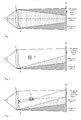
- the basic arrangement of video hologram and reconstruction shows Fig. 1 , In the light direction, a light source 1, a lens 2, a hologram 3 and a viewer plane 4 are arranged in succession.
- the observer plane 4 corresponds to the Fourier plane of the inverse transformation of the video hologram with the diffraction orders.
- the light source 1 is imaged by an optical system, represented by the lens 2, in the observer plane 4. If a hologram 3 is inserted, then it is represented in the observer plane 4 as a Fourier inverse transformation.
- the hologram 3 with periodic openings produces equidistantly continued diffraction orders in the Viewer plane 4, wherein the holographic coding, for example by means of the so-called detour phase effect, takes place in the higher diffraction orders.
- the 1st or the -1 Diffraction order selected as a viewer window 5. Unless expressly stated otherwise, the description of the invention will be based on the 1st diffraction order.
- the selected 1st diffraction order forms the reconstructed hologram 3 as a Fourier transform, it does not represent the actual three-dimensional scene 6. It serves only as a viewer window 5 through which the three-dimensional scene 6 can be viewed (see FIG. Fig. 2 ). Inside the light beam of the 1st diffraction order, the actual three-dimensional scene 6 is indicated in the form of a circle. The scene thus lies within the reconstruction cone, which is spanned by the hologram 3 and the observer window 5. The scene is created as a Fresnel transform of the hologram, while the viewer window is part of the Fourier transform.
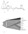
- the Fig. 3 shows the holographic coding.
- the three-dimensional scene is built up of points. With the observer window 5 as the base and the selected point 7 in the scene 6 as a peak, a cone is projected extended through this point onto the hologram 3. The result is a projection area 8 in the video hologram 3, in which this point is holographically encoded.
- To calculate the phase values one can determine the path lengths from the considered point 7 to the cells of the hologram 3. With this reconstruction, the size of the observer window 5 is maintained in the periodicity interval.
- the considered point 7 were coded in the entire hologram 3, the reconstructed would be extended beyond the periodicity interval.
- the viewer zones from adjacent diffraction orders would overlap, with the viewer seeing a periodic continuation of the point 7 under consideration. Such a coded surface would appear washed out by multiple overlays in their contours.
- the intensity decrease is used to higher diffraction orders towards the suppression of crosstalk to other viewer window.
- the Fig. 4 schematically shows an intensity profile of the light on the diffraction orders, which is formed by the width of the openings in the CGH.
- the diffraction orders are plotted on the abscissa.
- the 1st diffraction order represents the observer window 5 for the left eye, that is to say the left observer window, through which the three-dimensional scene 6 can be viewed.
- the crosstalk in a viewer window for the right eye is suppressed by the drop in intensity to higher orders and additionally by the zero of the intensity distribution.
- the observer can also view the scene 6 of the hologram 3 with both eyes (see FIG. Fig. 5 ).
- the right viewer window 5 ' became the -1.
- the 1st diffraction order was chosen according to the position of the light source 1. There arises analogously the left viewing window 5.
- the two-light sources 1 and 1 ' represent the corresponding three-dimensional scenes 6 and 6' (not shown here) in a fixed position relative to the eyes.
- the hologram 3 is recoded each time the light sources 1 and 1 'are switched on.
- the two light sources 1 and 1 ' can simultaneously reconstruct the hologram 3 at the two observer windows 5 and 5'.
- the light sources 1 and 1 ' are tracked so that the two observer windows 5 and 5' remain localized on the eyes of the observer. This also applies to movements in the normal, ie perpendicular to the video hologram. Furthermore, several viewers can also view a three-dimensional scene by creating additional viewer windows by connecting additional light sources.
- the present description and the figures disclose inter alia a video hologram and a device for the reconstruction of video holograms with an optical system consisting of at least one real or virtual point and / or line-shaped, sufficiently coherent light source and a lens, and the video hologram of matrix-like or otherwise regularly arranged cells with at least one controllable in amplitude and / or phase opening per cell and a viewer plane at the location of the light source image.
- a viewer window 5 is located in a periodicity interval of the reconstruction as a Fourier transform of the video hologram 3, through which a three-dimensional scene 6 can be viewed. The extent of the viewer window 5 is not larger than the periodicity interval.
- the viewer window 5 could be limited and positioned approximately at one eye, one eye distance of an observer, or at another suitable area.
- a second observer window 5 ' is associated with the other eye of the observer by connecting a second real or virtual, sufficiently coherent light source 1' at another suitable location to a light source pair in the optical system.
- the optical system and the video hologram 3 are arranged such that the higher diffraction orders of the video hologram 3 for the first observer window 5 have a zero or an intensity minimum at the location of the second observer window 5 '.
- the video hologram 3 for the second eye can be recoded.
- the light sources can be positioned by mechanical or electronic displacement, by movable mirrors, or in any other suitable manner.
- the information for determining the position of the light sources is supplied by at least one position sensor depending on the position of the viewer or viewers.
- the color reconstruction of a video hologram 3 from cells arranged in a matrix or in a regular manner takes place with at least three openings per cell controllable for the primary colors in amplitude and / or phase, the coding for the openings being carried out separately for each primary color.
- the colored reconstruction is carried out by at least three consecutively executed reconstructions in the primary colors.
- the invention relates to video holograms and devices for reconstructing video holograms with an optical system comprising light source 1, lens 2 and the video hologram 3 of matrix-like or regularly arranged cells with at least one amplitude and / or phase controllable opening per cell ,
- the video holograms and devices for reconstructing them are characterized in that holographic video representations of extended spatial objects 6 can be realized in a wide range of observers by means of controllable displays in real time, the objects being generated either computer-generated or otherwise.
- the space bandwith product (SBP) of the hologram is thereby reduced to a minimum by using the periodicity interval of the Fourier spectrum in the inverse transformation plane as observer window 5, by means of which the object in the preceding space becomes visible.
- the mobility of the viewer (s) is achieved by tracking the observer window.
- Advantageous applications can be found in the television, multimedia, games and construction sectors, in military and medical technology as well as in other areas of business and society.
Landscapes
- Physics & Mathematics (AREA)
- General Physics & Mathematics (AREA)
- Mathematical Physics (AREA)
- Holo Graphy (AREA)
- Stereoscopic And Panoramic Photography (AREA)
- Testing, Inspecting, Measuring Of Stereoscopic Televisions And Televisions (AREA)
- Apparatus For Radiation Diagnosis (AREA)
Abstract
Description
Die Erfindung betrifft ein Videohologramm und eine Einrichtung zur Rekonstruktion von Videohologrammen mit einem optischen System, bestehend wenigstens aus einer Lichtquelle, einer Linse und dem Videohologramm aus matrixförmig oder in anderer Weise regulär angeordneten Zellen mit mindestens einer in Amplitude und/oder Phase steuerbaren Öffnung je Zelle sowie einer Betrachterebene am Ort des Lichtquellenbildes.The invention relates to a video hologram and a device for reconstructing video holograms with an optical system, comprising at least one light source, a lens and the video hologram of matrix-like or otherwise regularly arranged cells with at least one controllable in amplitude and / or phase opening per cell and a viewer level at the location of the light source image.
Es sind Einrichtungen zur Rekonstruktion von Videohologrammen mit akustooptischen Modulatoren (AOM) bekannt (Stephen A. Benton, Joel S. Kollin: Three dimensional display system,
Eine andere Möglichkeit, große Videohologramme zu erzeugen, bietet das sogenannte Tiling-Verfahren mit Computer Generierten Hologrammen (CGH). Nach diesem aus
Bei den beispielsweise aus
Bei Fourierhologrammen findet bekanntlich die Rekonstruktion in eine Ebene als direkte oder inverse Fouriertransformierte des Hologramms statt. Diese Rekonstruierte setzt sich periodisch mit einem Periodizitätsintervall fort, dessen Ausdehnung umgekehrt proportional zum Pitch im Hologramm ist.In Fourier holograms, reconstruction is known to take place in a plane as direct or inverse Fourier transform of the hologram. This reconstructed periodically continues with a periodicity interval whose extent is inversely proportional to the pitch in the hologram.
Wenn die Ausdehnung der Rekonstruierten des Fourierhologramms größer als das Periodizitätsintervall ist, überlappen sich benachbarte Beugungsordnungen. Mit zunehmender Verringerung der Auflösung, also wachsendem Pitch der Öffnungen, werden die Ränder der Rekonstruierten durch Überlappung aus den höheren Beugungsordnungen zunehmend gestört. Die nutzbare Rekonstruktion wird dadurch in ihrer Ausdehnung mehr und mehr eingeschränkt.If the extent of the reconstructions of the Fourier hologram is greater than the periodicity interval, adjacent diffraction orders overlap. With increasing reduction of the resolution, ie increasing pitch of the openings, the edges of the reconstructed are increasingly disturbed by overlapping from the higher diffraction orders. The usable reconstruction is thereby more and more restricted in its extent.
Will man größere Periodizätsintervalle und damit also größere Betrachterwinkel erzielen, nähert sich der erforderliche Pitch im Hologramm der Lichtwellenlänge. Um dann möglichst große Szenen darstellen zu können, müssen aber auch die CGH entsprechend groß sein. Beide Forderungen verlangen ein großes CGH mit sehr vielen Öffnungen, das in Form von Displays mit steuerbaren Öffnungen gegenwärtig nicht realisierbar ist (s.
Beide Parameter, Pitch und Hologrammgröße, werden durch das sogenannte Space-Bandwith-Produkt (SBP) als Anzahl der Öffnungen im Hologramm beschrieben. Soll die Rekonstruktion von einem CGH mit steuerbaren Öffnungen mit 50 cm Breite so erfolgen, dass ein Betrachter die Szene im Abstand von 1 m innerhalb eines horizontalen Betrachterfensters von 50 cm sehen kann, beträgt das SPB in horizontaler Richtung etwa 0,5*106. Dem entsprechen im CGH 500.000 steuerbare Öffnungen mit einem Abstand von 1 µm Bei einem Aspekt-Verhältnis von 4:3 ergeben sich in vertikaler Richtung entsprechend 375.000 Öffnungen. Das CGH enthält somit 3,75*1011 Öffnungen, wenn man drei Farbsubpixel berücksichtigt. Diese Zahl verdreifacht sich noch, wenn man bedenkt, dass im CGH mit steuerbaren Öffnungen meist nur Amplituden beeinflusst werden können. Die Phasenkodierung erfolgt dann über den sogenannten Detourphasen-Effekt, wofür mindestens drei äquidistante Öffnungen je Abtastpunkt erforderlich sind. SLM mit so vielen steuerbaren Öffnungen sind derzeit nicht bekannt.Both parameters, pitch and hologram size, are described by the so-called space bandwith product (SBP) as the number of apertures in the hologram. If the reconstruction of a CGH with controllable openings with a width of 50 cm so that a viewer can see the scene at a distance of 1 m within a horizontal viewer window of 50 cm, the SPB is in the horizontal direction about 0.5 * 10 6th The equivalent in CGH 500,000 controllable openings with a distance of 1 micron With an aspect ratio of 4: 3 result in the vertical direction accordingly 375,000 openings. The CGH thus contains 3.75 * 10 11 openings, considering three color subpixels. This number is tripled, considering that in CGH with controllable openings usually only amplitudes can be influenced. The phase coding then takes place via the so-called detour phase effect, for which at least three equidistant openings per scanning point are required. SLM's with so many controllable openings are currently unknown.
Die Hologrammwerte müssen aus den zu rekonstruierenden Szenen berechnet werden. Bei einer Farbtiefe von 1 Byte für jede der drei Grundfarben und einer Frame-Rate von 50 Hz benötigt ein CGH einen Informationsfluss von 50*1012 = 0,5*1014 Byte/s. Fouriertransformationen von Datenströmen dieser Größe übersteigen die Leistung derzeit einsetzbarer Rechner bei weitem und schließen eine Hologramm-Berechnung auf Basis lokaler Rechner aus. Aber auch eine Übertragung dieser Informationsmenge über Datennetze ist für den normalen Nutzer gegenwärtig nicht realisierbar.The hologram values must be calculated from the scenes to be reconstructed. With a color depth of 1 byte for each of the three primary colors and a frame rate of 50 Hz, a CGH requires an information flow of 50 * 10 12 = 0.5 * 10 14 bytes / s. Fourier transforms of data streams of this size far exceed the performance of currently usable computers and exclude a hologram computation based on local computation. But even a transmission of this amount of information via data networks is currently not feasible for the normal user.
Um die umfangreichen Rechenvorgänge zu verringern, wird beispielsweise auch vorgeschlagen, das Hologramm nicht vollständig zu berechnen, sondern nur in den Teilen, die direkt vom Betrachter eingesehen werden können oder die sich ändern. In der oben schon genannten Patentschrift
Die Nachteile der bekannten Verfahren bestehen zusammengefasst darin, dass die Anordnungen mit akusto-optischen Modulatoren zu voluminös sind und nicht auf heutige aus der Flachbildschirmtechnik bekannte Abmessungen reduziert werden können, dass die Videohologramme nach dem Tiling-Verfahren zweistufige Verfahren mit großem technologischen Aufwand sind, die sich schwerlich auf Desktop-Größe reduzieren lassen und dass schließlich die Anordnungen auf der Basis von SLM mit steuerbaren Öffnungen zu klein sind, um große Szenen rekonstruieren zu können. Dazu fehlen momentan steuerbare große SLM mit extrem kleinen Pitches sowie die erforderlichen Rechenleistungen und die erforderliche hohe Bandbreite der Netzwerke.The disadvantages of the known methods are summarized in that the arrangements with acousto-optic modulators are too bulky and can not be reduced to today's known from the flat-panel dimensions, that the video holograms are by the tiling method two-stage process with great technological effort, the difficult to reduce to desktop size, and that, finally, SLM based arrangements with controllable openings are too small to reconstruct large scenes. Currently there are no controllable large SLM with extremely small pitches as well as the required computing power and the required high bandwidth of the networks.
Der Erfindung liegt die Aufgabe zugrunde, die angeführten Nachteile zu umgehen und ausgedehnte Videodarstellungen von Hologrammen in Echtzeit und für große Betrachterwinkel zu ermöglichen.The invention has for its object to obviate the disadvantages mentioned and to allow extended video display of holograms in real time and for large viewing angles.
Diese Aufgabe wird erfindungsgemäß mit den im Patentanspruch 1 aufgeführten Merkmalen gelöst. Vorteilhafte Ausgestaltungen der Erfindung sind in den Patentansprüchen 2 bis 21 angegeben.This object is achieved with the features listed in
Die erfindungsgemäßen Videohologramme und Einrichtungen zur Rekonstruktion von Videohologrammen mit steuerbaren Öffnungen sehen vor, dass in der Betrachterebene mindestens ein Betrachterfenster in einem Periodizitätsintervall als direkte oder inverse Fouriertransformierte des Videohologramms gebildet wird, durch das hindurch ein Betrachter eine dreidimensionale Szene als Rekonstruktion sehen kann. Die Ausdehnung des Betrachterfensters entspricht maximal dem Periodizitätsintervall in der Ebene der Fourier-Rücktransformation am Ort des Lichtquellenbildes. Das Betrachterfenster spannt zusammen mit dem Hologramm einen Kegelstumpf auf, der die gesamte dreidimensionale Szene als Fresnel-Transformierte des Videohologramms enthält.The video holograms and devices for reconstructing video holograms with controllable openings according to the invention provide that in the observer plane at least one observer window is formed in a periodicity interval as direct or inverse Fourier transform of the video hologram, through which a viewer can see a three-dimensional scene as a reconstruction. The extent of the observer window corresponds at most to the periodicity interval in the plane of the inverse Fourier transformation at the location of the light source image. The viewer window, together with the hologram, tightens a truncated cone containing the entire three-dimensional scene as a Fresnel transform of the video hologram.
Das Betrachterfenster ist in Ausbildung der Erfindung in etwa auf ein Auge, einen Augenabstand eines Betrachters oder auf einen anderen geeigneten Bereich begrenzt und positioniert.The viewer window is limited and positioned in an embodiment of the invention approximately to an eye, an eye relief of an observer or to another suitable area.
Im Rahmen der Erfindung ist vorgesehen, dass dem anderen Auge des Betrachters analog ein Betrachterfenster zugeordnet wird. Das erfolgt dadurch, dass die betrachtete Lichtquelle entsprechend versetzt oder durch Zuschalten einer zweiten reellen oder virtuellen, hinreichend kohärenten Lichtquelle an einem anderen geeigneten Ort zu einem Lichtquellenpaar im optischen System ergänzt wird. Auf diese Weise wird die beidäugige Betrachtung der dreidimensionalen Szene durch zwei zugehörige Betrachterfenster ermöglicht. Dabei kann der Inhalt des Videohologramms synchron mit dem Zuschalten des zweiten Betrachterfensters entsprechend der Augenposition geändert, d.h. umkodiert werden.In the context of the invention, it is provided that a viewer window is analogously assigned to the other eye of the viewer. This takes place in that the considered light source is offset accordingly or supplemented by connecting a second real or virtual, sufficiently coherent light source at another suitable location to a light source pair in the optical system. In this way, the two-eyed viewing of the three-dimensional scene is made possible by two associated observer windows. In this case, the content of the video hologram can be changed, ie transcoded, synchronously with the connection of the second observer window in accordance with the eye position.
Bei mehreren Betrachtern können so durch Zuschalten weiterer Lichtquellen entsprechend viele Betrachterfenster erzeugt werden.In the case of several observers, correspondingly many observer windows can be generated by connecting additional light sources.
Für die Einrichtung zur Rekonstruktion eines Videohologramms besteht ein anderer wesentlicher Erfindungsgedanke darin, das optische System und das Videohologramm so anzuordnen, dass die höheren Beugungsordnungen des Videohologramms für das erste Betrachterfenster eine Nullstelle bzw. ein Intensitätsminimum am Ort des zweiten Betrachterfensters aufweisen. Damit wird ein Übersprechen eines Betrachterfensters für ein Auge auf das andere Auge eines Betrachters oder auf andere Betrachter verhindert. Der Intensitätsabfall des Lichts zu höheren Beugungsordnungen hin aufgrund der endlichen Breite der Öffnungen des Videohologramms oder/und der Minima des Intensitätsverlaufs wird so vorteilhaft ausgenutzt. Bei zum Beispiel rechteckigen Öffnungen entsteht als Intensitätsverlauf eine sinc2-Funktion, die schnell abfällt und eine mit größer werdenden Abständen abnehmende sin2-Funktion darstellt.For the device for reconstructing a video hologram, another essential idea of the invention is to arrange the optical system and the video hologram such that the higher diffraction orders of the video hologram for the first observer window have a zero or an intensity minimum at the location of the second observer window. This prevents crosstalk of an observer window for one eye on the other eye of a viewer or on other observers. The intensity decrease of the light to higher diffraction orders due to the finite width of the openings of the video hologram and / or the minima of the intensity profile is thus advantageously utilized. In the case of, for example, rectangular openings, a sinc 2 function arises as the intensity profile, which drops off rapidly and represents a decreasing sin 2 function with increasing intervals.
Für das Videohologramm sind nur so viele Werte zu berechnen, wie das Display Öffnungen hat. Auf die gleiche Anzahl von Werten ist die Übertragung der Daten vom Computer oder vom Netz auf das Display als Hologramm beschränkt. Der Datenstrom unterscheidet sich daher praktisch nicht von dem heute schon durch die übliche Displaytechnik zu verarbeitenden Datenstrom. Das soll anhand eines Beispiels verdeutlicht werden.For the video hologram, only as many values are to be calculated as the display has openings. The same number of values limit the transfer of data from the computer or network to the display as a hologram. The data stream is therefore virtually indistinguishable from the data stream that is already being processed today by conventional display technology. This will be illustrated by an example.
Reduziert man das Betrachterfenster durch Wahl eines hinreichend grob auflösenden Displays beispielsweise von horizontal 50 cm und vertikal 37,5 cm auf 1 cm x 1 cm, so entspricht das einer Reduzierung der Anzahl der Öffnungen im Hologramm auf 1/1875. In gleicher Weise wird bei einem Transfer über ein Netzwerk die erforderliche Bandbreite reduziert. Bei den nach bekannten Verfahren hergestellten Videohologrammen mit erforderlichen 1012 Öffnungen reduzieren sich diese im Beispiel auf etwa 5*108 Pixel. Durch das verbleibende Betrachterfenster kann die Szene vollständig betrachtet werden. Diese Anforderungen an Pitch und Hologrammgrösse entsprechend dem Space-Bandwith-Produkt können heute verfügbare Displays bereits erfüllen. Damit können auf kostengünstige Weise große Echtzeit-Videohologramme auf Displays mit großem Pitch für einen großen Betrachterbereich realisiert werden.Reducing the viewer window by choosing a sufficiently coarse resolution display, for example, from horizontal 50 cm and vertical 37.5 cm to 1 cm x 1 cm, this corresponds to a reduction in the number of openings in the hologram to 1/1875. Similarly, when transferring over a network, the required bandwidth is reduced. In the case of the video holograms with required 10 12 openings produced according to known methods, these reduce in the example to approximately 5 × 10 8 pixels. Through the remaining observer window, the scene can be fully viewed. These pitch and hologram size requirements according to the space bandwith product can already meet today's available displays. This can be realized in a cost effective manner large real-time video holograms on displays with large pitch for a large viewer area.
Die Nachführung des Betrachterfensters (Tracking) wird durch mechanischen oder elektronischen Versatz der Lichtquellen, durch bewegliche Spiegel oder von auf andere geeignete Weise positionierbare Lichtquellen realisiert. Mit dem Verschieben der Lichtquellenbilder verschieben sich auch die Betrachterfenster. Bewegt sich der Betrachter, wird/werden die Lichtquelle/n so im Raum verschoben, dass die Betrachterfenster den Augen des Betrachters folgen. Dadurch wird gesichert, dass die Betrachter auch bei Bewegung die rekonstruierte dreidimensionale Szene sehen und andererseits ihre Bewegungsfreiheit nicht eingeschränkt ist. Für die Positionsdetektion der Betrachter sind verschiedene Systeme bekannt, die hier vorteilhaft einsetzbar sind, beispielsweise auf Magnetsensoren basierende.The tracking of the viewer window (tracking) is realized by mechanical or electronic offset of the light sources, by moving mirrors or by other suitable positionable light sources. Moving the light source images also moves the viewer windows. As the viewer moves, the light source (s) are / are moved in the room so that the viewer windows follow the viewer's eyes. This ensures that the observers see the reconstructed three-dimensional scene even when moving, and that their freedom of movement is not restricted. For the position detection of the viewer, various systems are known, which can be used advantageously, for example, based on magnetic sensors.
Mit den erfindungsgemäßen Mitteln ist auch die farbige Rekonstruktion eines Videohologramms effektiv möglich. Dabei ist vorgesehen, dass die Rekonstruktion mit mindestens drei für die Grundfarben in Amplitude und/oder Phase steuerbaren Öffnungen je Zelle erfolgt, wobei die Kodierung für die Öffnungen für jede Grundfarbe separat vorgenommen wird. Eine andere Möglichkeit der farbigen Rekonstruktion eines Videohologramms besteht darin, wenigstens drei nacheinander ausgeführte Rekonstruktionen in den Grundfarben auf der Grundlage der erfindungsgemäßen Einrichtung durchzuführen.The colored reconstruction of a video hologram is also effectively possible with the agents according to the invention. It is provided that the reconstruction is carried out with at least three controllable for the basic colors in amplitude and / or phase openings per cell, wherein the coding for the openings for each base color is made separately. Another possibility of color reconstruction of a video hologram is to perform at least three successive reconstructions in the basic colors on the basis of the device according to the invention.
Mit der vorliegenden Erfindung können vorteilhafterweise holografische Darstellungen von ausgedehnten räumlichen Szenen mittels steuerbarer Displays, wie TFT-Flachdisplays, in Echtzeit und für große Betrachterwinkel erzeugt werden. Diese Videohologramme sind vorteilhafterweise im Fernseh-, Multimedia-, Spiele- und Konstruktionsbereich, in der Militär- und in der Medizintechnik und in anderen Bereichen von Wirtschaft und Gesellschaft anwendbar. Die dreidimensionalen Szenen können computergeneriert oder auf andere Weise erzeugt werden.With the present invention, holographic representations of extended spatial scenes can be advantageously generated by means of controllable displays, such as flat TFT displays, in real time and for large viewing angles. These video holograms are advantageously applicable in the television, multimedia, games and engineering, military and medical and other fields of business and society. The three-dimensional scenes can be computer generated or otherwise generated.
Ein Ausführungsbeispiel der Erfindung ist in den Zeichnungen dargestellt und wird im Folgenden näher beschrieben.An embodiment of the invention is illustrated in the drawings and will be described in more detail below.
Es zeigen
- Fig. 1
- eine prinzipielle Darstellung eines Videohologramms und einer Einrichtung zur Rekonstruktion von Videohologrammen mit der Entstehung der Beugungsordnungen und der Lage eines Betrachterfensters,
- Fig. 2
- eine prinzipielle Darstellung einer Einrichtung zur Rekonstruktion von Videohologrammen mit einer dreidimensionalen Szene, die durch ein Betrachterfenster hindurch betrachtet werden kann,
- Fig. 3
- eine prinzipielle Darstellung einer Einrichtung zur Rekonstruktion von Videohologrammen mit der Kodierung der dreidimensionalen Szene in einem Teil des Videohologramms, so dass die Beugungsordnungen nicht überlappen,
- Fig. 4
- einen Intensitätsverlauf des Lichtes in der Betrachterebene in Abhängigkeit von den Beugungsordnungen und
- Fig. 5
- eine prinzipielle Darstellung einer Einrichtung zur Rekonstruktion von Videohologrammen mit der Lage der Betrachterfenster für beide Augen eines Betrachters hinsichtlich der Beugungsordnungen zur Vermeidung von Übersprechen.
- Fig. 1
- a schematic representation of a video hologram and a device for the reconstruction of video holograms with the formation of the diffraction orders and the position of a viewer window,
- Fig. 2
- a schematic representation of a device for the reconstruction of video holograms with a three-dimensional scene that can be viewed through a viewer window,
- Fig. 3
- a schematic representation of a device for the reconstruction of video holograms with the coding of the three-dimensional scene in a part of the video hologram, so that the diffraction orders do not overlap,
- Fig. 4
- an intensity profile of the light in the observer plane in dependence on the diffraction orders and
- Fig. 5
- a schematic representation of a device for the reconstruction of video holograms with the position of the viewer window for both eyes of a viewer with respect to the diffraction orders to avoid crosstalk.
Eine Einrichtung zur Rekonstruktion von Videohologrammen besteht aus dem Videohologramm, einer hinreichend kohärenten reellen oder virtuellen punkt- oder linienförmigen Lichtquelle und aus einem optischen System. Das Videohologramm selbst setzt sich aus matrixförmig oder in anderer Weise regulär angeordneten Zellen zusammen, die mindestens eine in Amplitude und/oder Phase steuerbare Öffnung je Zelle enthalten. Das optische System zur Rekonstruktion des Videohologramms lässt sich in bekannter Weise z.B. einfach durch ein optisches Abbildungssystem, bestehend aus einem punkt- oder linienförmigen Laser und einer hinreichend kohärenten Lichtquelle realisieren.One means of reconstructing video holograms consists of the video hologram, a sufficiently coherent real or virtual point or line light source, and an optical system. The video hologram itself is composed of matrix-like or otherwise regularly arranged cells which contain at least one amplitude and / or phase controllable opening per cell. The optical system for reconstructing the video hologram can be produced in a known manner e.g. simply by an optical imaging system, consisting of a point or line laser and a sufficiently coherent light source realize.
Die grundsätzliche Anordnung von Videohologramm und Rekonstruktion zeigt
Die Lichtquelle 1 wird durch ein optisches System, repräsentiert durch die Linse 2, in die Betrachterebene 4 abgebildet. Setzt man ein Hologramm 3 ein, so wird es in der Betrachterebene 4 als Fourier-Rücktransformation dargestellt. Das Hologramm 3 mit periodischen Öffnungen erzeugt äquidistant fortgesetzte Beugungsordnungen in der Betrachterebene 4, wobei die holografische Kodierung, beispielsweise mittels des sogenannten Detourphasen-Effektes, in die höheren Beugungsordnungen erfolgt. Da die Intensität nach höheren Beugungsordnungen hin abnimmt, wird in der Regel die 1. oder die -1. Beugungsordnung als Betrachterfenster 5 gewählt. Wenn nicht ausdrücklich anders angegeben, wird zur Darlegung der Erfindung im Weiteren von der 1. Beugungsordnung ausgegangen.The
Die Ausdehnung der Rekonstruktion wurde hier so gewählt, dass sie in ihrer Größe mit dem Periodizitätsintervall der 1. Beugungsordnung in der Betrachterebene 4 übereinstimmt. Somit schließen sich höhere Beugungsordnungen ohne Lücke, aber auch ohne Überlappung aneinander an.The extent of the reconstruction was chosen here so that it coincides in size with the periodicity interval of the 1st diffraction order in the
Die ausgewählte 1. Beugungsordnung bildet zwar als Fouriertransformierte die Rekonstruierte des Hologramms 3, stellt aber nicht die eigentliche dreidimensionale Szene 6 dar. Sie dient nur als Betrachterfenster 5, durch das hindurch die dreidimensionale Szene 6 betrachtet werden kann (s.
Die
Vorteilhafterweise wird der Intensitätsabfall zu höheren Beugungsordnungen hin zur Unterdrückung des Übersprechens auf andere Betrachterfenster genutzt. Die
Der Betrachter kann die Szene 6 des Hologramms 3 natürlich auch mit beiden Augen betrachten (s.
Für das linke Auge wurde die 1. Beugungsordnung entsprechend der Lage der Lichtquelle 1 gewählt. Dort entsteht analog das linke Betrachtungsfenster 5. Erfindungsgemäß werden mit den zwei Lichtquellen 1 und 1' die entsprechenden dreidimensionalen Szenen 6 und 6' (hier nicht gezeigt) ortsfest bezüglich der Augen dargestellt. Dazu wird das Hologramm 3 beim Zuschalten der Lichtquellen 1 und 1' jeweils neu kodiert. Alternativ können die beiden Lichtquellen 1 und 1' gleichzeitig das Hologramm 3 an den beiden Betrachterfenstern 5 und 5' rekonstruieren.For the left eye, the 1st diffraction order was chosen according to the position of the
Bewegt sich der Betrachter, werden die Lichtquellen 1 und 1' so nachgeführt, dass die beiden Betrachterfenster 5 und 5' auf den Augen des Betrachters lokalisiert bleiben. Dies gilt auch bei Bewegungen in der Normalen, also senkrecht zum Videohologramm. Weiterhin können auch mehrere Betrachter eine dreidimensionale Szene betrachten, indem durch Zuschalten weiterer Lichtquellen zusätzliche Betrachterfenster entstehen.If the observer moves, the
Die vorliegende Beschreibung und die Fig. offenbaren u.a. ein Videohologramm und eine Einrichtung zur Rekonstruktion von Videohologrammen mit einem optischen System, bestehend aus mindestens einer reellen oder virtuellen punkt- und/oder linienförmigen, hinreichend kohärenten Lichtquelle und einer Linse, sowie dem Videohologramm aus matrixförmig oder in anderer Weise regulär angeordneten Zellen mit mindestens einer in Amplitude und/oder Phase steuerbaren Öffnung je Zelle und einer Betrachterebene am Ort des Lichtquellenbildes. In der Betrachterebene ist ein Betrachterfenster 5 in einem Periodizitätsintervall der Rekonstruktion als Fouriertransformierte des Videohologramms 3 lokalisiert, durch welches hindurch eine dreidimensionale Szene 6 betrachtbar ist. Die Ausdehnung des Betrachterfensters 5 ist nicht größer als das Periodizitätsintervall.The present description and the figures disclose inter alia a video hologram and a device for the reconstruction of video holograms with an optical system consisting of at least one real or virtual point and / or line-shaped, sufficiently coherent light source and a lens, and the video hologram of matrix-like or otherwise regularly arranged cells with at least one controllable in amplitude and / or phase opening per cell and a viewer plane at the location of the light source image. In the observer plane, a
Das Betrachterfenster 5 könnte in etwa auf ein Auge, einen Augenabstand eines Betrachters oder auf einen anderen geeigneten Bereich begrenzt und positioniert sein.The
Dem anderen Auge des Betrachters ist ein zweites Betrachterfenster 5' durch Zuschalten einer zweiten reellen oder virtuellen, hinreichend kohärenten Lichtquelle 1' an einem anderen geeigneten Ort zu einem Lichtquellenpaar im optischen System zugeordnet.A second observer window 5 'is associated with the other eye of the observer by connecting a second real or virtual, sufficiently coherent light source 1' at another suitable location to a light source pair in the optical system.
Das optische System und das Videohologramm 3 sind so angeordnet, dass die höheren Beugungsordnungen des Videohologramms 3 für das erste Betrachterfenster 5 eine Nullstelle bzw. ein Intensitätsminimum am Ort des zweiten Betrachterfensters 5' aufweisen.The optical system and the
Synchron mit dem Zuschalten des zweiten Betrachterfensters 5' ist das Videohologramm 3 für das zweite Auge umkodierbar.Synchronous with the connection of the second observer window 5 ', the
Für mehrere Betrachter sind mehrere Lichtquellen zuschaltbar.For several observers several light sources are switchable.
Die Lichtquellen sind durch mechanischen oder elektronischen Versatz, durch bewegliche Spiegel, oder auf andere geeignete Weise positionierbar.The light sources can be positioned by mechanical or electronic displacement, by movable mirrors, or in any other suitable manner.
Die Information zur Bestimmung der Position der Lichtquellen wird von wenigstens einem Positionsgeber in Abhängigkeit von der Position des oder der Betrachter geliefert.The information for determining the position of the light sources is supplied by at least one position sensor depending on the position of the viewer or viewers.
Die farbige Rekonstruktion eines Videohologramms 3 aus matrixförmig oder regulär angeordneten Zellen erfolgt mit mindestens drei für die Grundfarben in Amplitude und/oder Phase steuerbaren Öffnungen je Zelle, wobei die Kodierung für die Öffnungen für jede Grundfarbe separat erfolgt.The color reconstruction of a
Die farbige Rekonstruktion erfolgt durch wenigstens drei nacheinander ausgeführte Rekonstruktionen in den Grundfarben.The colored reconstruction is carried out by at least three consecutively executed reconstructions in the primary colors.
Zusammenfassend wird ausgeführt, dass die Erfindung Videohologramme und Einrichtungen zur Rekonstruktion von Videohologrammen mit einem optischen System betrifft, bestehend aus Lichtquelle 1, Linse 2 und dem Videohologramm 3 aus matrixförmig oder regulär angeordneten Zellen mit mindestens einer in Amplitude und/oder Phase steuerbaren Öffnung je Zelle. Die Videohologramme und Einrichtungen zur Rekonstruktion derselben zeichnen sich dadurch aus, dass holografische Videodarstellungen ausgedehnter räumlicher Objekte 6 in einem weiten Betrachterbereich mittels steuerbarer Displays in Echtzeit realisierbar sind, wobei die Objekte entweder computergeneriert oder auf andere Weise erzeugt werden. Das Space-Bandwith-Produkt (SBP) des Hologramms wird dabei auf ein Minimum reduziert, indem das Periodizitätsintervall des Fourierspektrums in der Rücktransformationsebene als Betrachterfenster 5 genutzt wird, durch welches das Objekt im davorliegenden Raum sichtbar wird. Die Beweglichkeit des/der Betrachter wird durch Nachführen des Betrachterfensters erreicht. Vorteilhafte Anwendungen bieten sich im Fernseh-, Multimedia-, Spiele- und Konstruktionsbereich, in der Militär- und Medizintechnik sowie in anderen Bereichen von Wirtschaft und Gesellschaft.In summary, it is stated that the invention relates to video holograms and devices for reconstructing video holograms with an optical system comprising
Claims (16)
Applications Claiming Priority (3)
| Application Number | Priority Date | Filing Date | Title |
|---|---|---|---|
| DE10253292 | 2002-11-13 | ||
| PCT/DE2003/003791 WO2004044659A2 (en) | 2002-11-13 | 2003-11-11 | Video hologram and device for reconstructing video holograms |
| EP03788795A EP1563346B1 (en) | 2002-11-13 | 2003-11-11 | Device for reconstructing video holograms |
Related Parent Applications (2)
| Application Number | Title | Priority Date | Filing Date |
|---|---|---|---|
| EP03788795A Division EP1563346B1 (en) | 2002-11-13 | 2003-11-11 | Device for reconstructing video holograms |
| EP03788795.7 Division | 2003-11-11 |
Publications (3)
| Publication Number | Publication Date |
|---|---|
| EP2138911A2 true EP2138911A2 (en) | 2009-12-30 |
| EP2138911A3 EP2138911A3 (en) | 2011-10-26 |
| EP2138911B1 EP2138911B1 (en) | 2022-06-22 |
Family
ID=32308559
Family Applications (3)
| Application Number | Title | Priority Date | Filing Date |
|---|---|---|---|
| EP09168975.2A Expired - Lifetime EP2138911B1 (en) | 2002-11-13 | 2003-11-11 | Device for reconstructing video holograms |
| EP09168963.8A Expired - Lifetime EP2138910B1 (en) | 2002-11-13 | 2003-11-11 | Device for reconstructing video holograms |
| EP03788795A Expired - Lifetime EP1563346B1 (en) | 2002-11-13 | 2003-11-11 | Device for reconstructing video holograms |
Family Applications After (2)
| Application Number | Title | Priority Date | Filing Date |
|---|---|---|---|
| EP09168963.8A Expired - Lifetime EP2138910B1 (en) | 2002-11-13 | 2003-11-11 | Device for reconstructing video holograms |
| EP03788795A Expired - Lifetime EP1563346B1 (en) | 2002-11-13 | 2003-11-11 | Device for reconstructing video holograms |
Country Status (13)
| Country | Link |
|---|---|
| US (14) | US7839548B2 (en) |
| EP (3) | EP2138911B1 (en) |
| JP (5) | JP4473133B2 (en) |
| KR (2) | KR100915431B1 (en) |
| CN (3) | CN102520604B (en) |
| AT (1) | ATE441877T1 (en) |
| BR (1) | BR0316222A (en) |
| DE (2) | DE10353439B4 (en) |
| HK (2) | HK1087198A1 (en) |
| IL (1) | IL168538A (en) |
| MX (1) | MXPA05005229A (en) |
| RU (2) | RU2293365C2 (en) |
| WO (1) | WO2004044659A2 (en) |
Cited By (1)
| Publication number | Priority date | Publication date | Assignee | Title |
|---|---|---|---|---|
| WO2017198713A3 (en) * | 2016-05-18 | 2018-01-18 | Seereal Technologies S.A. | Method for producing holograms |
Families Citing this family (122)
| Publication number | Priority date | Publication date | Assignee | Title |
|---|---|---|---|---|
| GB9903032D0 (en) * | 1999-02-11 | 1999-03-31 | Symbian Ltd | Messaging architecture |
| EP2138911B1 (en) * | 2002-11-13 | 2022-06-22 | SeeReal Technologies GmbH | Device for reconstructing video holograms |
| DE102004044111B4 (en) | 2004-09-08 | 2015-05-07 | Seereal Technologies Gmbh | Method and device for coding and reconstructing computer-generated video holograms |
| DE102004063838A1 (en) | 2004-12-23 | 2006-07-06 | Seereal Technologies Gmbh | Method and apparatus for calculating computer generated video holograms |
| DE102005021155B3 (en) | 2005-04-29 | 2006-11-23 | Seereal Technologies Gmbh | Controllable lighting device |
| ATE516521T1 (en) | 2005-05-06 | 2011-07-15 | Seereal Technologies Gmbh | DEVICE FOR THE HOLOGRAPHIC RECONSTRUCTION OF THREE-DIMENSIONAL SCENES |
| WO2007073731A1 (en) * | 2005-12-22 | 2007-07-05 | Seereal Technologies S.A. | Method for the multimodal representation of image contents on a display unit for video holograms, and multimodal display unit |
| KR101367573B1 (en) | 2005-12-22 | 2014-02-25 | 시리얼 테크놀로지즈 에스.에이. | Method for the compensation of an inhomogeneous brightness perception in holographically reconstructed scenes |
| DE102006003741B4 (en) * | 2006-01-18 | 2009-08-27 | Seereal Technologies S.A. | Method for coding a computer-generated hologram |
| DE102006004301A1 (en) * | 2006-01-20 | 2007-08-02 | Seereal Technologies S.A. | Method for supportive calculation of division of resources in technical network |
| DE102006018689A1 (en) * | 2006-04-13 | 2007-10-25 | Seereal Technologies S.A. | Method for rendering and generating computer-generated video holograms in real time |
| DE102006024356B4 (en) | 2006-05-19 | 2016-09-29 | Seereal Technologies S.A. | Holographic projection apparatus for reconstructing scenes and methods for holographic reconstruction |
| JP5265546B2 (en) | 2006-09-01 | 2013-08-14 | シーリアル テクノロジーズ ソシエテ アノニム | Method for generating video holograms in real time using sub-holograms |
| JP5266223B2 (en) | 2006-09-01 | 2013-08-21 | シーリアル テクノロジーズ ソシエテ アノニム | Method for generating computer video holograms in real time using propagation |
| US8368743B2 (en) | 2006-09-01 | 2013-02-05 | Seereal Technologies S.A. | Interface and circuit arrangement, in particular for holographic encoding units or holographic reproduction devices |
| DE102006042324B4 (en) * | 2006-09-01 | 2014-06-18 | Seereal Technologies S.A. | Method for generating computer-generated video holograms in real time by means of sub-holograms |
| DE102006041637B4 (en) * | 2006-09-05 | 2010-11-25 | Seereal Technologies S.A. | A playback device and method for tracking a viewer window |
| DE102006042467A1 (en) * | 2006-09-09 | 2008-03-27 | Seereal Technologies S.A. | Method and device for coding computer-generated holograms in pixelated light modulators |
| DE102006043297B4 (en) * | 2006-09-14 | 2010-12-09 | Seereal Technologies S.A. | A playback apparatus and method comprising means for tracking a viewer window |
| GB0709379D0 (en) * | 2007-05-16 | 2007-06-27 | Seereal Technologies Sa | Smart display extended |
| JP2010507823A (en) * | 2006-10-26 | 2010-03-11 | シーリアル テクノロジーズ ソシエテ アノニム | Small holographic display device |
| DE102007024237B4 (en) | 2007-05-21 | 2009-01-29 | Seereal Technologies S.A. | Holographic reconstruction system with optical waveguide tracking |
| TWI406115B (en) * | 2006-10-26 | 2013-08-21 | Seereal Technologies Sa | Holographic display device and method for generating holographic reconstruction of three dimensional scene |
| JP2010507824A (en) * | 2006-10-26 | 2010-03-11 | シーリアル テクノロジーズ ソシエテ アノニム | Holographic display device |
| DE102007024236A1 (en) | 2007-05-21 | 2008-11-27 | Seereal Technologies S.A. | Holographic reconstruction system with an array of controllable microprisms |
| TWI422999B (en) * | 2006-10-26 | 2014-01-11 | Seereal Technologies Sa | Holographic display device, manufacturing method thereof and method of generating holographic reconstruction |
| DE102006062377B4 (en) | 2006-12-19 | 2018-03-22 | Seereal Technologies S.A. | Method and holographic display device for reducing speckle |
| DE102006062376B4 (en) | 2006-12-19 | 2018-03-22 | Seereal Technologies S.A. | Method and display device for reducing speckle |
| DE102006062413A1 (en) | 2006-12-21 | 2008-06-26 | Seereal Technologies S.A. | Holographic projection device for enlarging a visibility region |
| DE102007005823A1 (en) | 2007-01-31 | 2008-08-07 | Seereal Technologies S.A. | Optical wavefront correction for a holographic projection system |
| DE102007005822A1 (en) | 2007-01-31 | 2008-08-07 | Seereal Technologies S.A. | Holographic reconstruction system with optical wave tracking |
| DE102007011561B4 (en) * | 2007-03-02 | 2016-03-17 | Seereal Technologies S.A. | Device for correcting the wavelength dependence in diffraction-based optical systems |
| DE102007011560A1 (en) | 2007-03-02 | 2008-09-04 | Seereal Technologies S.A. | Device for minimizing the bending dispersion in light modulators comprises a refractive optical element assigned to a light modulator |
| DE102007018266A1 (en) | 2007-04-10 | 2008-10-16 | Seereal Technologies S.A. | Holographic projection system with optical waveguide tracking and means for correcting the holographic reconstruction |
| US8218211B2 (en) | 2007-05-16 | 2012-07-10 | Seereal Technologies S.A. | Holographic display with a variable beam deflection |
| DE102007023740B4 (en) | 2007-05-16 | 2009-04-09 | Seereal Technologies S.A. | Method for generating video holograms for a holographic display device with random addressing |
| DE102007023737B4 (en) | 2007-05-16 | 2009-01-02 | Seereal Technologies S.A. | Method for generating video holograms in real time for extending a 3D rendering graphics pipeline |
| DE102007023738A1 (en) * | 2007-05-16 | 2009-01-08 | Seereal Technologies S.A. | Method and device for reconstructing a three-dimensional scene in a holographic display |
| US9581965B2 (en) | 2007-05-16 | 2017-02-28 | Seereal Technologies S.A. | Analytic method for computing video holograms in real time |
| DE102007023739B4 (en) * | 2007-05-16 | 2018-01-04 | Seereal Technologies S.A. | Method for rendering and generating color video holograms in real time and holographic display device |
| DE102007023785B4 (en) | 2007-05-16 | 2014-06-18 | Seereal Technologies S.A. | Analytical method for calculating video holograms in real time and holographic display device |
| GB0718626D0 (en) | 2007-05-16 | 2007-11-07 | Seereal Technologies Sa | Holograms |
| DE102007024235B4 (en) | 2007-05-21 | 2009-04-30 | Seereal Technologies S.A. | Holographic reconstruction system and method with extended visibility range |
| DE102007025069B4 (en) | 2007-05-21 | 2018-05-24 | Seereal Technologies S.A. | Holographic reconstruction system |
| DE102007028371B4 (en) | 2007-06-13 | 2012-05-16 | Seereal Technologies S.A. | Device for light modulation |
| DE102007036127A1 (en) | 2007-07-27 | 2009-01-29 | Seereal Technologies S.A. | Holographic reconstruction device |
| GB0716829D0 (en) * | 2007-08-31 | 2007-10-10 | Seereal Technologies Sa | Holographic display |
| DE102007045332B4 (en) * | 2007-09-17 | 2019-01-17 | Seereal Technologies S.A. | Holographic display for reconstructing a scene |
| TW200928624A (en) * | 2007-10-19 | 2009-07-01 | Seereal Technologies Sa | Light modulating device |
| GB0720484D0 (en) * | 2007-10-19 | 2007-11-28 | Seereal Technologies Sa | Cells |
| DE102007051521A1 (en) | 2007-10-19 | 2009-04-23 | Seereal Technologies S.A. | Dynamic Waveform Unit |
| GB2454246B (en) | 2007-11-02 | 2010-03-10 | Light Blue Optics Ltd | Holographic image display systems |
| DE102008000116A1 (en) | 2008-01-21 | 2009-07-30 | Seereal Technologies S.A. | Illumination unit for a holographic reconstruction system |
| MD3896G2 (en) * | 2008-01-25 | 2009-12-31 | Государственный Университет Молд0 | Device for recovery of multiplex holograms |
| DE102008000589B4 (en) | 2008-03-11 | 2018-02-01 | Seereal Technologies S.A. | Method for coding computer-generated holograms in pixelated light modulators |
| DE102008002692B4 (en) * | 2008-06-26 | 2019-02-21 | Seereal Technologies S.A. | Display device for three-dimensional holographic or stereoscopic display of spatial objects and method for determining an apodization function for an apodisation mask |
| DE102008040581B4 (en) * | 2008-07-21 | 2017-06-01 | Seereal Technologies S.A. | Controllable light modulation device |
| USD666663S1 (en) | 2008-10-20 | 2012-09-04 | X6D Limited | 3D glasses |
| USD603445S1 (en) | 2009-03-13 | 2009-11-03 | X6D Limited | 3D glasses |
| USD624952S1 (en) | 2008-10-20 | 2010-10-05 | X6D Ltd. | 3D glasses |
| USRE45394E1 (en) | 2008-10-20 | 2015-03-03 | X6D Limited | 3D glasses |
| CA2684513A1 (en) * | 2008-11-17 | 2010-05-17 | X6D Limited | Improved performance 3d glasses |
| US8542326B2 (en) | 2008-11-17 | 2013-09-24 | X6D Limited | 3D shutter glasses for use with LCD displays |
| DE102008054438A1 (en) | 2008-12-09 | 2010-06-24 | Seereal Technologies S.A. | Optical component for deflecting light rays passing through the optical component |
| USD646451S1 (en) | 2009-03-30 | 2011-10-04 | X6D Limited | Cart for 3D glasses |
| US8927801B2 (en) | 2009-04-13 | 2015-01-06 | The Procter & Gamble Company | Absorbent articles comprising wetness indicators |
| USD650956S1 (en) | 2009-05-13 | 2011-12-20 | X6D Limited | Cart for 3D glasses |
| USD672804S1 (en) | 2009-05-13 | 2012-12-18 | X6D Limited | 3D glasses |
| USD671590S1 (en) | 2010-09-10 | 2012-11-27 | X6D Limited | 3D glasses |
| USD692941S1 (en) | 2009-11-16 | 2013-11-05 | X6D Limited | 3D glasses |
| USD669522S1 (en) | 2010-08-27 | 2012-10-23 | X6D Limited | 3D glasses |
| USD662965S1 (en) | 2010-02-04 | 2012-07-03 | X6D Limited | 3D glasses |
| TWI561941B (en) | 2010-04-01 | 2016-12-11 | Seereal Technologies Sa | Method and device for encoding three-dimensional scenes which include transparent objects in a holographic system |
| US9395690B2 (en) | 2010-07-06 | 2016-07-19 | Seereal Technologies S.A. | Beam divergence and various collimators for holographic or stereoscopic displays |
| USD664183S1 (en) | 2010-08-27 | 2012-07-24 | X6D Limited | 3D glasses |
| KR101670927B1 (en) * | 2010-11-05 | 2016-11-01 | 삼성전자주식회사 | Display apparatus and method |
| US8913149B1 (en) | 2010-11-30 | 2014-12-16 | Integrity Applications Incorporated | Apparatus and techniques for enhanced resolution imaging |
| US9291828B2 (en) | 2010-12-22 | 2016-03-22 | Seereal Technologies S.A. | Combined light modulation device for tracking users |
| DE102011005154B4 (en) | 2010-12-22 | 2022-03-31 | Seereal Technologies S.A. | Light modulation device for a holographic or an autostereoscopic display |
| DE102011053037A1 (en) | 2011-08-26 | 2013-02-28 | Seereal Technologies S.A. | lighting device |
| KR101507202B1 (en) * | 2011-11-16 | 2015-04-08 | 엘지디스플레이 주식회사 | Spatial Light Modulating Panel Using Transparent Type Liquid Crystal Display Panel And 3D Display Device Using The Same |
| DE102011056006B4 (en) | 2011-12-01 | 2016-03-10 | Seereal Technologies S.A. | Method for coding a hologram in a light modulation device |
| KR101841624B1 (en) * | 2012-01-25 | 2018-03-26 | 삼성전자주식회사 | Method and apparatus for generating fast 3d hologram |
| KR102124632B1 (en) | 2012-01-26 | 2020-06-22 | 시리얼 테크놀로지즈 에스.에이. | Display with observer tracking |
| US9581966B1 (en) | 2012-02-15 | 2017-02-28 | Integrity Applications Incorporated | Systems and methodologies related to 3-D imaging and viewing |
| US9934614B2 (en) | 2012-05-31 | 2018-04-03 | Microsoft Technology Licensing, Llc | Fixed size augmented reality objects |
| US9354606B1 (en) | 2012-07-31 | 2016-05-31 | Integrity Applications Incorporated | Systems and methodologies related to generating projectable data for 3-D viewing |
| USD711959S1 (en) | 2012-08-10 | 2014-08-26 | X6D Limited | Glasses for amblyopia treatment |
| US9219905B1 (en) | 2012-08-31 | 2015-12-22 | Integrity Applications Incorporated | Systems and methodologies related to formatting data for 3-D viewing |
| EP2900284A1 (en) | 2012-09-26 | 2015-08-05 | The Procter & Gamble Company | Anti-leaching liquid-activated formulation |
| AU2013237745A1 (en) | 2012-10-09 | 2014-04-24 | Aristocrat Technologies Australia Pty Limited | A gaming system and a method of gaming |
| CN103186090B (en) * | 2013-03-14 | 2015-08-26 | 北京工业大学 | The online reconstruction display system of digital hologram imaging and method |
| US9310769B2 (en) | 2013-03-28 | 2016-04-12 | Disney Enterprises, Inc. | Coarse integral holographic display |
| WO2014195013A1 (en) | 2013-06-06 | 2014-12-11 | Seereal Technologis S.A. | Device and method for calculating holographic data |
| FR3015743A1 (en) * | 2013-12-23 | 2015-06-26 | Orange | METHOD OF PROCESSING A SEQUENCE OF HOLOGRAPHIC IMAGES, DEVICES, SIGNALS, DEVICES AND COMPUTER PROGRAM THEREFOR |
| KR102208960B1 (en) | 2014-04-09 | 2021-01-28 | 삼성전자주식회사 | Holographic display |
| US9473764B2 (en) | 2014-06-27 | 2016-10-18 | Microsoft Technology Licensing, Llc | Stereoscopic image display |
| KR20160027384A (en) * | 2014-08-29 | 2016-03-10 | 전자부품연구원 | Exhibition Apparatus using the Transparent Display and Hologram |
| DE102015101203B4 (en) | 2015-01-28 | 2021-06-17 | Seereal Technologies S.A. | Light modulating device and holographic display device |
| KR101800929B1 (en) | 2015-01-29 | 2017-11-23 | 한국전자통신연구원 | Method and apparatus for correcting distortion on holographic display |
| KR102384223B1 (en) | 2015-02-26 | 2022-04-07 | 삼성전자주식회사 | Method of generating light modulating signal for 3-dimensional image display, and method and apparatus for displaying 3-dimensional image |
| US10073263B2 (en) * | 2015-03-04 | 2018-09-11 | Oculus Vr, Llc | Sparse projection for a virtual reality system |
| DE102015205873A1 (en) | 2015-04-01 | 2016-10-06 | Seereal Technologies S.A. | Method for calculating holograms for holographic reconstruction of two-dimensional and / or three-dimensional scenes |
| CN105223796B (en) * | 2015-09-08 | 2018-09-11 | 北京邮电大学 | Hologram computational methods based on near-eye display device and device |
| KR20180098395A (en) | 2015-12-28 | 2018-09-03 | 시리얼 테크놀로지즈 에스.에이. | Display device and method for optimizing image quality |
| CN114296332A (en) | 2016-03-02 | 2022-04-08 | 视瑞尔技术公司 | Lighting device |
| CN108020977A (en) * | 2016-10-28 | 2018-05-11 | 京东方科技集团股份有限公司 | Display device and its display methods |
| RU2650086C1 (en) | 2016-12-22 | 2018-04-06 | Самсунг Электроникс Ко., Лтд. | Holographic image display device and a method of operation of a control unit contained in it |
| US10969740B2 (en) | 2017-06-27 | 2021-04-06 | Nvidia Corporation | System and method for near-eye light field rendering for wide field of view interactive three-dimensional computer graphics |
| CN109581850B (en) * | 2017-09-29 | 2021-03-05 | 京东方科技集团股份有限公司 | Holographic display method and holographic display device |
| DE112018006228A5 (en) | 2017-12-07 | 2020-09-03 | Seereal Technologies S.A. | HEAD-UP DISPLAY |
| CN108305320B (en) * | 2018-02-09 | 2021-06-04 | 重庆大学 | Self-adaptive sliding window reconstruction method for improving large-field holographic imaging quality |
| US10753579B2 (en) | 2018-07-20 | 2020-08-25 | Flex-N-Gate Advanced Product Development, Llc | Animated 3D image multiplier |
| EP3824622A4 (en) | 2018-07-20 | 2021-09-08 | Flex-N-gate Advanced Product Development, LLC | Floating image generation |
| US20210231996A1 (en) | 2018-08-16 | 2021-07-29 | Seereal Technolgies S.A. | Light modulation device |
| US11454928B2 (en) * | 2018-11-06 | 2022-09-27 | Samsung Electronics Co., Ltd. | Holographic display apparatus and method for providing expanded viewing window |
| DE112021004254A5 (en) | 2020-08-10 | 2023-06-01 | Seereal Technologies S.A. | Device and method for calculating hologram data |
| KR102510926B1 (en) * | 2020-10-14 | 2023-03-16 | 울산과학기술원 | A system for designating holographic colors and method for designating holographic colors based on dithering mask |
| US11798370B2 (en) | 2020-10-26 | 2023-10-24 | Lnw Gaming, Inc. | Gaming machine and method with symbol array alteration |
| KR20220133675A (en) * | 2021-03-25 | 2022-10-05 | 현대자동차주식회사 | Pop Up Floating Type Hologram System and Vehicle Thereof |
| US11907435B1 (en) | 2021-08-02 | 2024-02-20 | Omar Kevin Ubilla | Transformable apparatus with retractable display |
| WO2024058438A1 (en) * | 2022-09-15 | 2024-03-21 | 삼성전자 주식회사 | Electronic device providing holographic image and operating method of electronic device |
Citations (5)
| Publication number | Priority date | Publication date | Assignee | Title |
|---|---|---|---|---|
| US5172251A (en) | 1990-04-12 | 1992-12-15 | Massachusetts Institute Of Technology | Three dimensional display system |
| WO2000075698A1 (en) | 1999-06-09 | 2000-12-14 | Holographic Imaging Llc | Holographic displays |
| WO2001095016A1 (en) | 2000-06-09 | 2001-12-13 | Holographic Imaging Llc | Computation time reduction for three-dimensional displays |
| EP0992163B1 (en) | 1997-06-28 | 2002-04-24 | Holographic Imaging LLC | Autostereoscopic display |
| US6437919B1 (en) | 1997-10-15 | 2002-08-20 | Holographic Imaging Llc | System for the production of a dynamic image for display |
Family Cites Families (107)
| Publication number | Priority date | Publication date | Assignee | Title |
|---|---|---|---|---|
| US4028323A (en) * | 1968-02-19 | 1977-06-07 | Ciba-Geigy Ag | Process for making azo compounds by coupling with nitrosated heterocyclic primary amines |
| US3635726A (en) * | 1968-09-20 | 1972-01-18 | Griffith Laboratories | Method of producing soy protein concentrates |
| US3966982A (en) * | 1973-06-18 | 1976-06-29 | Dravo Corporation | Process and apparatus for treating oleaginous seed material |
| US3957353A (en) | 1974-03-08 | 1976-05-18 | The Board Of Trustees Of The Leland Stanford University | Multiemulsion transparency providing separate phase and amplitude control |
| US3897574A (en) * | 1974-03-21 | 1975-07-29 | Central Soya Co | Purification of ethanol extractant in soy protein concentrate process |
| US4188399A (en) * | 1974-12-23 | 1980-02-12 | Miles Laboratories, Inc. | Process for preparing a heat coagulable viscous protein |
| CA1066329A (en) * | 1976-03-16 | 1979-11-13 | Edward J. Falk | Tandem brake master cylinder |
| US4285862A (en) * | 1976-09-30 | 1981-08-25 | General Foods, Limited | Protein isolate product |
| US4072670A (en) * | 1976-10-26 | 1978-02-07 | Mead Johnson & Company | Low phytate isoelectric precipitated soy protein isolate |
| US4091120A (en) * | 1976-11-15 | 1978-05-23 | Mead Johnson & Company | Liquid dietary product containing soy protein membrane isolate |
| US4151828A (en) * | 1977-06-28 | 1979-05-01 | Solarpower, Inc. | Solar energy collection tube |
| US4321280A (en) * | 1977-12-01 | 1982-03-23 | General Foods Corporation | Textured oil seed protein products |
| US4284656A (en) * | 1979-12-14 | 1981-08-18 | Hwa Stephen C P | Novel protein curd product and process of preparation |
| US4435438A (en) * | 1980-12-29 | 1984-03-06 | A. E. Staley Manufacturing Company | Soy isolate suitable for use in imitation cheese |
| US4346122A (en) * | 1980-12-29 | 1982-08-24 | A. E. Staley Manufacturing Company | Low-viscosity, high-NSI, heat-gelling soy isolates |
| US4368151A (en) * | 1981-08-10 | 1983-01-11 | A. E. Staley Manufacturing Company | 7S And 11S vegetable protein fractionation and isolation |
| US4460613A (en) * | 1982-11-01 | 1984-07-17 | Ralston Purina Company | Basal material for the preparation of tofu |
| US4530788A (en) * | 1982-12-03 | 1985-07-23 | Stauffer Chemical Company | Oil seed proteins evidencing improved functionality |
| US4500454A (en) * | 1982-12-03 | 1985-02-19 | Stauffer Chemical Company | Vegetable protein evidencing improved solution viscosity |
| US4493854A (en) * | 1983-09-20 | 1985-01-15 | The United States Of America As Represented By The Secretary Of Agriculture | Production of defatted soybean products by supercritical fluid extraction |
| US5290959A (en) * | 1985-09-10 | 1994-03-01 | Vitamins, Inc. | Mass separation of materials |
| US5086166A (en) * | 1987-02-13 | 1992-02-04 | The Texas A&M University System | Protein foods and food ingredients and processes for producing them from defatted and undefatted oilseeds |
| US5097017A (en) * | 1989-12-20 | 1992-03-17 | Central Soya Company, Inc. | Process for making soy protein concentrate |
| US5191449A (en) | 1992-02-03 | 1993-03-02 | Cfc Applied Holographics | Animated holographic stereogram display |
| JPH0627864A (en) * | 1992-07-10 | 1994-02-04 | Fujitsu Ltd | Method and device for generating computer hologram |
| JPH0635391A (en) | 1992-07-20 | 1994-02-10 | Fujitsu Ltd | Stereoscopic display device |
| JPH07261125A (en) * | 1994-03-24 | 1995-10-13 | Olympus Optical Co Ltd | Projection type image display device |
| US5798964A (en) * | 1994-08-29 | 1998-08-25 | Toshiba Corporation | FRAM, FRAM card, and card system using the same |
| JP2765489B2 (en) * | 1994-09-30 | 1998-06-18 | 不二製油株式会社 | Soy protein and its manufacturing method |
| JP2989115B2 (en) * | 1995-03-27 | 1999-12-13 | 浜松ホトニクス株式会社 | Stereoscopic display method and stereoscopic display device |
| CA2146811C (en) | 1995-04-11 | 2003-07-01 | David Michael Moore Dean | Method and apparatus for presenting stereoscopic images |
| US5936069A (en) * | 1995-12-06 | 1999-08-10 | Iowa State University Research Foundation | Process for producing improved soy protein concentrate from genetically-modified soybeans |
| ES2120878B1 (en) * | 1996-01-05 | 1999-06-01 | Alejo Trevijano Jose Javier | ELECTRONIC STEREOSCOPIC SYSTEM. |
| DE69737779T2 (en) | 1996-02-29 | 2008-03-06 | Hamamatsu Photonics K.K., Hamamatsu | Holographic imaging and display device and method |
| AU720838B2 (en) * | 1996-04-09 | 2000-06-15 | E.I. Du Pont De Nemours And Company | Novel isoflavone-enriched soy protein product and method for its manufacture |
| US6108440A (en) * | 1996-06-28 | 2000-08-22 | Sony Corporation | Image data converting method |
| JP3546618B2 (en) * | 1996-12-19 | 2004-07-28 | 不二製油株式会社 | How to make soy protein |
| US6171640B1 (en) * | 1997-04-04 | 2001-01-09 | Monsanto Company | High beta-conglycinin products and their use |
| JP3798511B2 (en) * | 1997-06-11 | 2006-07-19 | 浜松ホトニクス株式会社 | Computer generated hologram display |
| US6330088B1 (en) | 1998-02-27 | 2001-12-11 | Zebra Imaging, Inc. | Method and apparatus for recording one-step, full-color, full-parallax, holographic stereograms |
| US6710920B1 (en) | 1998-03-27 | 2004-03-23 | Sanyo Electric Co., Ltd | Stereoscopic display |
| DE19825192A1 (en) * | 1998-06-05 | 1999-12-16 | Joerg Gutjahr | Projection screen |
| KR20010074685A (en) | 1998-07-10 | 2001-08-09 | 추후보정 | Projection system based on reconfigurable holographic optics |
| JP2000059822A (en) * | 1998-08-06 | 2000-02-25 | Toshiba Corp | Stereoscopic video display device |
| JP4026242B2 (en) * | 1998-08-19 | 2007-12-26 | 松下電器産業株式会社 | Optical 3D video display device |
| JP3505404B2 (en) * | 1998-10-16 | 2004-03-08 | 理想科学工業株式会社 | Hologram pattern determination device, determination method thereof, and recording medium |
| US6844458B2 (en) * | 1998-11-20 | 2005-01-18 | Ip Holdings, L.L.C. | Vegetable oil refining |
| EP1008919A1 (en) * | 1998-12-09 | 2000-06-14 | Communauté Européenne (CE) | Computer assisted holographic method and apparatus for reproducing three-dimensional images |
| US6335043B1 (en) * | 1999-08-03 | 2002-01-01 | Haokui Jiang | Method for extracting soybean proteins using an enzyme |
| US6665100B1 (en) * | 1999-08-10 | 2003-12-16 | Zebra Imaging, Inc. | Autostereoscopic three dimensional display using holographic projection |
| US6677327B1 (en) * | 1999-11-24 | 2004-01-13 | Archer-Daniels-Midland Company | Phytosterol and phytostanol compositions |
| IL134701A0 (en) * | 2000-02-23 | 2001-04-30 | J P M E D Ltd | Homogeneous solid matrix containing vegetable proteins |
| DE10008710C2 (en) * | 2000-02-24 | 2002-01-10 | Loh Optikmaschinen Ag | Device for centering clamping of optical lenses for their edge processing |
| WO2002013633A1 (en) * | 2000-08-11 | 2002-02-21 | Food & Packaging Centre Management Limited | Oil seed processing |
| AU2001283571A1 (en) * | 2000-08-18 | 2002-03-04 | Central Soya Company Inc. | Soy protein product and process for its manufacture |
| CN2439045Y (en) * | 2000-08-31 | 2001-07-11 | 深圳市泛彩溢实业有限公司 | Holographic liquid crystal display |
| JP5058427B2 (en) * | 2000-09-29 | 2012-10-24 | 不二製油株式会社 | Production method of soy protein |
| GB0027103D0 (en) * | 2000-11-07 | 2000-12-20 | Secr Defence | Improved 3D display |
| JP2002149045A (en) * | 2000-11-15 | 2002-05-22 | Victor Co Of Japan Ltd | Hologram recording medium |
| US6630195B1 (en) * | 2000-11-21 | 2003-10-07 | Cargill, Incorporated | Process for producing oilseed protein products |
| US6787173B2 (en) * | 2000-11-30 | 2004-09-07 | Kraft Foods Holdings, Inc. | Method of deflavoring soy-derived materials |
| US7045163B2 (en) * | 2000-11-30 | 2006-05-16 | Kraft Foods Holdings, Inc. | Method of deflavoring soy-derived materials |
| US20040161512A1 (en) * | 2000-11-30 | 2004-08-19 | Kraft Foods Holdings, Inc. | Method of deflavoring soy-derived materials for use in dough-based and baked products |
| US20040161513A1 (en) * | 2000-11-30 | 2004-08-19 | Kraft Foods Holdings, Inc. | Method of preparation of high quality soy-containing meat and meat analog products |
| US7175869B2 (en) * | 2000-11-30 | 2007-02-13 | Kraft Foods Holdings, Inc. | Method of deflavoring soy-derived materials using electrodialysis |
| US7037547B2 (en) * | 2000-11-30 | 2006-05-02 | Kraft Foods Holdings, Inc. | Method of deflavoring soy-derived materials for use in beverages |
| US20040170743A1 (en) * | 2000-11-30 | 2004-09-02 | Kraft Foods Holdings, Inc. | Method of deflavoring soy-derived materials confectionary type products |
| US6576253B2 (en) * | 2000-12-05 | 2003-06-10 | Pbm Pharmaceuticals, Inc. | Food bars containing nutritional supplements |
| JP4632331B2 (en) | 2000-12-19 | 2011-02-16 | 大日本印刷株式会社 | Method for producing hologram master for optical duplication |
| EP1408770A2 (en) * | 2001-01-16 | 2004-04-21 | Solae, Llc | Gelling vegetable protein |
| KR100425293B1 (en) * | 2001-02-01 | 2004-03-30 | 삼성전자주식회사 | Stereoscopic display device |
| DE60229836D1 (en) * | 2001-02-20 | 2008-12-24 | Solae Holdings Llc | HIGHLY SOY PROTEIN OF HIGH MOLECULAR WEIGHT |
| RU2316223C2 (en) * | 2001-05-04 | 2008-02-10 | Баркон Ньютрасайнс (Мб) Корп. | Method for producing of protein isolate from oil-bearing crop seeds |
| GB2379351A (en) * | 2001-09-04 | 2003-03-05 | Holographic Imaging Llc | Illuminating a computer generated hologram |
| US20030059514A1 (en) * | 2001-09-10 | 2003-03-27 | Villagran Francisco Valentino | Compositions comprising soy protein and processes of their preparation |
| DE60229283D1 (en) * | 2001-11-20 | 2008-11-20 | Burcon Nutrascience Mb Corp | CONTINUOUS METHOD FOR THE PRODUCTION OF OILSAAT PROTEIN ISOLATE |
| US7090863B2 (en) * | 2001-11-30 | 2006-08-15 | Inpharma S.A. | Hypocholesterolemic composition and methods of use |
| ATE427043T1 (en) * | 2001-12-13 | 2009-04-15 | Burcon Nutrascience Mb Corp | INCREASED YIELD PROTEIN COLLECTION |
| CA2484746A1 (en) * | 2002-05-07 | 2003-11-20 | Solae Llc | Low isoflavones, high saponins soy protein product and process for producing the same |
| DE60323368D1 (en) * | 2002-06-21 | 2008-10-16 | Burcon Nutrascience Mb Corp | PROTEIN EXTRACTION OF CANOLA OIL SEEDS FLOUR |
| GB2391475B (en) * | 2002-08-10 | 2005-02-02 | Reckitt Benckiser | A packaged hair-removing layer, its manufacture and its use |
| EP2138911B1 (en) * | 2002-11-13 | 2022-06-22 | SeeReal Technologies GmbH | Device for reconstructing video holograms |
| US20060019017A1 (en) * | 2002-12-09 | 2006-01-26 | Navpreet Singh | Soy protein concentrate with high gel strength and the process for making the same |
| US7018668B2 (en) * | 2003-02-06 | 2006-03-28 | Procter & Gamble Co. | Low fat creamer compositions |
| WO2004072739A1 (en) * | 2003-02-12 | 2004-08-26 | Dai Nippon Printing Co., Ltd. | Computer-generated hologram |
| US8021703B2 (en) * | 2003-06-20 | 2011-09-20 | Burcon Nutrascience (Mb) Corp. | Oil seed meal preparation |
| US20050084470A1 (en) * | 2003-10-15 | 2005-04-21 | Unilever Home & Personal Care Usa, Division Of Conopco, Inc. | Skin care and cleansing compositions containing oil seed product |
| US20050095345A1 (en) * | 2003-11-04 | 2005-05-05 | Schillinger John A. | Soy products and soy product production methods and apparatus |
| CN1901808B (en) * | 2003-12-26 | 2011-11-16 | 不二制油株式会社 | Creams, whipped products thereof, dry powders thereof and process for producing the same |
| US20050220979A1 (en) * | 2004-04-02 | 2005-10-06 | Craig Baumer | High soy protein nuggets and applications in food products |
| GB2416108A (en) * | 2004-07-16 | 2006-01-18 | Solae Llc | Protein-containing dairy product |
| US7556836B2 (en) * | 2004-09-03 | 2009-07-07 | Solae, Llc | High protein snack product |
| US20060062889A1 (en) * | 2004-09-17 | 2006-03-23 | Solae, Llc. | Soy protein-containing composition |
| US7169425B2 (en) * | 2004-09-17 | 2007-01-30 | Solae, Llc | Size exclusion chromatography process for the preparation of an improved soy protein-containing composition |
| US20060121176A1 (en) * | 2004-12-06 | 2006-06-08 | Solae, Llc | Soy protein-containing composition having improved functionality |
| US7332192B2 (en) * | 2004-12-17 | 2008-02-19 | Solae, Llc | Soy protein isolate |
| DE102004063838A1 (en) * | 2004-12-23 | 2006-07-06 | Seereal Technologies Gmbh | Method and apparatus for calculating computer generated video holograms |
| US20070014896A1 (en) * | 2005-07-18 | 2007-01-18 | Wong Theodore M | Calcium containing soy protein isolate composition |
| US20070031577A1 (en) * | 2005-07-20 | 2007-02-08 | Novozymes A/S | Method for producing a soy protein product |
| US20070042103A1 (en) * | 2005-08-17 | 2007-02-22 | Solae, Llc. | Isolated Soy Protein Having High Molecular Weight Protein Fractions and Low Molecular Weight Protein Fractions |
| US20070042106A1 (en) * | 2005-08-17 | 2007-02-22 | Solae, Llc | High Protein Food Bars Comprising Sugar Alcohols and Having Improved Texture and Shelf-Life |
| US20070077345A1 (en) * | 2005-09-30 | 2007-04-05 | Borders Cheryl K | High-protein soy-wheat crisps |
| US20070092633A1 (en) * | 2005-10-25 | 2007-04-26 | Navpreet Singh | Soy protein product with a high sterol and tocopherol content and process for its manufacture |
| DE102007005822A1 (en) * | 2007-01-31 | 2008-08-07 | Seereal Technologies S.A. | Holographic reconstruction system with optical wave tracking |
| JP5206951B2 (en) * | 2008-06-24 | 2013-06-12 | 株式会社ニコン | Image display device |
| KR101759252B1 (en) * | 2011-01-21 | 2017-07-19 | 삼성전자주식회사 | Three-dimensional holographic display using active shutter |
| JP5903805B2 (en) * | 2011-08-31 | 2016-04-13 | ブラザー工業株式会社 | Developing apparatus and manufacturing method thereof |
-
2003
- 2003-11-11 EP EP09168975.2A patent/EP2138911B1/en not_active Expired - Lifetime
- 2003-11-11 DE DE10353439A patent/DE10353439B4/en not_active Expired - Lifetime
- 2003-11-11 MX MXPA05005229A patent/MXPA05005229A/en active IP Right Grant
- 2003-11-11 DE DE50311875T patent/DE50311875D1/en not_active Expired - Lifetime
- 2003-11-11 RU RU2005118086/28A patent/RU2293365C2/en not_active IP Right Cessation
- 2003-11-11 CN CN201210020062.XA patent/CN102520604B/en not_active Expired - Lifetime
- 2003-11-11 CN CNB200380103105XA patent/CN100437393C/en not_active Expired - Lifetime
- 2003-11-11 AT AT03788795T patent/ATE441877T1/en active
- 2003-11-11 BR BR0316222-2A patent/BR0316222A/en not_active Application Discontinuation
- 2003-11-11 EP EP09168963.8A patent/EP2138910B1/en not_active Expired - Lifetime
- 2003-11-11 WO PCT/DE2003/003791 patent/WO2004044659A2/en active Application Filing
- 2003-11-11 KR KR1020087005127A patent/KR100915431B1/en active IP Right Grant
- 2003-11-11 US US10/534,877 patent/US7839548B2/en not_active Expired - Lifetime
- 2003-11-11 CN CN2008100967419A patent/CN101349889B/en not_active Expired - Lifetime
- 2003-11-11 KR KR1020057008370A patent/KR100891293B1/en active IP Right Grant
- 2003-11-11 JP JP2004550657A patent/JP4473133B2/en not_active Expired - Lifetime
- 2003-11-11 RU RU2007105102/28A patent/RU2363025C2/en not_active IP Right Cessation
- 2003-11-11 EP EP03788795A patent/EP1563346B1/en not_active Expired - Lifetime
-
2005
- 2005-05-11 IL IL168538A patent/IL168538A/en not_active IP Right Cessation
-
2006
- 2006-06-21 HK HK06107036.5A patent/HK1087198A1/en not_active IP Right Cessation
- 2006-06-29 US US11/427,638 patent/US20060238843A1/en not_active Abandoned
- 2006-06-29 US US11/427,649 patent/US20060238840A1/en not_active Abandoned
- 2006-06-29 US US11/427,640 patent/US7315408B2/en not_active Expired - Lifetime
- 2006-06-29 US US11/427,644 patent/US7929189B2/en not_active Expired - Lifetime
- 2006-06-29 US US11/427,655 patent/US20060238844A1/en not_active Abandoned
- 2006-06-29 US US11/427,645 patent/US7924484B2/en not_active Expired - Lifetime
- 2006-06-29 US US11/427,629 patent/US8314981B2/en active Active
-
2007
- 2007-11-09 US US11/937,991 patent/US8027071B2/en not_active Expired - Lifetime
-
2009
- 2009-06-30 HK HK09105855.4A patent/HK1128338A1/en not_active IP Right Cessation
-
2010
- 2010-01-18 JP JP2010008453A patent/JP5371801B2/en not_active Expired - Fee Related
- 2010-10-12 US US12/902,309 patent/US8174744B2/en not_active Expired - Fee Related
-
2011
- 2011-08-24 US US13/216,761 patent/US8384974B2/en not_active Expired - Lifetime
-
2013
- 2013-01-24 US US13/748,643 patent/US8941902B2/en not_active Expired - Lifetime
- 2013-03-15 JP JP2013054064A patent/JP5788427B2/en not_active Expired - Lifetime
-
2015
- 2015-01-08 US US14/592,227 patent/US9989920B2/en not_active Expired - Lifetime
- 2015-03-20 JP JP2015058246A patent/JP6249977B2/en not_active Expired - Lifetime
-
2017
- 2017-10-10 JP JP2017196995A patent/JP6701143B2/en not_active Expired - Lifetime
-
2018
- 2018-06-04 US US15/997,217 patent/US10884377B2/en not_active Expired - Lifetime
Patent Citations (5)
| Publication number | Priority date | Publication date | Assignee | Title |
|---|---|---|---|---|
| US5172251A (en) | 1990-04-12 | 1992-12-15 | Massachusetts Institute Of Technology | Three dimensional display system |
| EP0992163B1 (en) | 1997-06-28 | 2002-04-24 | Holographic Imaging LLC | Autostereoscopic display |
| US6437919B1 (en) | 1997-10-15 | 2002-08-20 | Holographic Imaging Llc | System for the production of a dynamic image for display |
| WO2000075698A1 (en) | 1999-06-09 | 2000-12-14 | Holographic Imaging Llc | Holographic displays |
| WO2001095016A1 (en) | 2000-06-09 | 2001-12-13 | Holographic Imaging Llc | Computation time reduction for three-dimensional displays |
Cited By (2)
| Publication number | Priority date | Publication date | Assignee | Title |
|---|---|---|---|---|
| WO2017198713A3 (en) * | 2016-05-18 | 2018-01-18 | Seereal Technologies S.A. | Method for producing holograms |
| US11397406B2 (en) | 2016-05-18 | 2022-07-26 | Seereal Technologies S.A. | Method for producing holograms |
Also Published As
Similar Documents
| Publication | Publication Date | Title |
|---|---|---|
| EP1563346B1 (en) | Device for reconstructing video holograms | |
| DE102004044111B4 (en) | Method and device for coding and reconstructing computer-generated video holograms | |
| EP1880252B1 (en) | Projection device and method for holographic reconstruction of scenes | |
| DE102005023743B4 (en) | Projection apparatus and method for holographic reconstruction of scenes | |
| DE102007025069B4 (en) | Holographic reconstruction system | |
| EP1974246B1 (en) | Projection device for the holographic reconstruction of scenes | |
| DE102006062377B4 (en) | Method and holographic display device for reducing speckle | |
| DE102006062376B4 (en) | Method and display device for reducing speckle | |
| DE102007023785B4 (en) | Analytical method for calculating video holograms in real time and holographic display device | |
| DE102006024356B4 (en) | Holographic projection apparatus for reconstructing scenes and methods for holographic reconstruction | |
| DE112007003043B4 (en) | Holographic projection device and method for observing a reconstructed scene | |
| WO2009037219A1 (en) | Holographic display having improved reconstruction quality | |
| WO2008025839A1 (en) | Method for generating video holograms in real time by means of subholograms | |
| DE102015205873A1 (en) | Method for calculating holograms for holographic reconstruction of two-dimensional and / or three-dimensional scenes | |
| DE102007019277A1 (en) | Device for generating holographic reconstructions with light modulators | |
| DE102007023738A1 (en) | Method and device for reconstructing a three-dimensional scene in a holographic display | |
| EP2181361B1 (en) | Holographic reconstruction device | |
| WO2008025844A1 (en) | Method for generating computer-generated video holograms in real time by means of propagation | |
| DE102006004299A1 (en) | Computer generated video hologram sequence data compression method, involves underlying all viewable object points in object point of same defined phase value, so that unchanged points of object imply unchanged hologram values |
Legal Events
| Date | Code | Title | Description |
|---|---|---|---|
| PUAI | Public reference made under article 153(3) epc to a published international application that has entered the european phase |
Free format text: ORIGINAL CODE: 0009012 |
|
| AC | Divisional application: reference to earlier application |
Ref document number: 1563346 Country of ref document: EP Kind code of ref document: P |
|
| AK | Designated contracting states |
Kind code of ref document: A2 Designated state(s): AT BE BG CH CY CZ DE DK EE ES FI FR GB GR HU IE IT LI LU MC NL PT RO SE SI SK TR |
|
| RAP1 | Party data changed (applicant data changed or rights of an application transferred) |
Owner name: SEEREAL TECHNOLOGIES GMBH |
|
| PUAL | Search report despatched |
Free format text: ORIGINAL CODE: 0009013 |
|
| AK | Designated contracting states |
Kind code of ref document: A3 Designated state(s): AT BE BG CH CY CZ DE DK EE ES FI FR GB GR HU IE IT LI LU MC NL PT RO SE SI SK TR |
|
| RIC1 | Information provided on ipc code assigned before grant |
Ipc: H04N 13/00 20060101ALI20110921BHEP Ipc: G03H 1/22 20060101AFI20110921BHEP |
|
| 17P | Request for examination filed |
Effective date: 20120426 |
|
| STAA | Information on the status of an ep patent application or granted ep patent |
Free format text: STATUS: EXAMINATION IS IN PROGRESS |
|
| 17Q | First examination report despatched |
Effective date: 20161222 |
|
| STAA | Information on the status of an ep patent application or granted ep patent |
Free format text: STATUS: EXAMINATION IS IN PROGRESS |
|
| APBK | Appeal reference recorded |
Free format text: ORIGINAL CODE: EPIDOSNREFNE |
|
| APBN | Date of receipt of notice of appeal recorded |
Free format text: ORIGINAL CODE: EPIDOSNNOA2E |
|
| APBR | Date of receipt of statement of grounds of appeal recorded |
Free format text: ORIGINAL CODE: EPIDOSNNOA3E |
|
| APAF | Appeal reference modified |
Free format text: ORIGINAL CODE: EPIDOSCREFNE |
|
| APBT | Appeal procedure closed |
Free format text: ORIGINAL CODE: EPIDOSNNOA9E |
|
| GRAP | Despatch of communication of intention to grant a patent |
Free format text: ORIGINAL CODE: EPIDOSNIGR1 |
|
| STAA | Information on the status of an ep patent application or granted ep patent |
Free format text: STATUS: GRANT OF PATENT IS INTENDED |
|
| RIC1 | Information provided on ipc code assigned before grant |
Ipc: G03H 1/08 20060101ALI20210812BHEP Ipc: H04N 13/00 20180101ALI20210812BHEP Ipc: G03H 1/22 20060101AFI20210812BHEP |
|
| INTG | Intention to grant announced |
Effective date: 20210826 |
|
| GRAJ | Information related to disapproval of communication of intention to grant by the applicant or resumption of examination proceedings by the epo deleted |
Free format text: ORIGINAL CODE: EPIDOSDIGR1 |
|
| GRAP | Despatch of communication of intention to grant a patent |
Free format text: ORIGINAL CODE: EPIDOSNIGR1 |
|
| INTG | Intention to grant announced |
Effective date: 20211008 |
|
| GRAJ | Information related to disapproval of communication of intention to grant by the applicant or resumption of examination proceedings by the epo deleted |
Free format text: ORIGINAL CODE: EPIDOSDIGR1 |
|
| GRAP | Despatch of communication of intention to grant a patent |
Free format text: ORIGINAL CODE: EPIDOSNIGR1 |
|
| STAA | Information on the status of an ep patent application or granted ep patent |
Free format text: STATUS: GRANT OF PATENT IS INTENDED |
|
| GRAJ | Information related to disapproval of communication of intention to grant by the applicant or resumption of examination proceedings by the epo deleted |
Free format text: ORIGINAL CODE: EPIDOSDIGR1 |
|
| GRAP | Despatch of communication of intention to grant a patent |
Free format text: ORIGINAL CODE: EPIDOSNIGR1 |
|
| INTG | Intention to grant announced |
Effective date: 20211207 |
|
| INTG | Intention to grant announced |
Effective date: 20211217 |
|
| GRAJ | Information related to disapproval of communication of intention to grant by the applicant or resumption of examination proceedings by the epo deleted |
Free format text: ORIGINAL CODE: EPIDOSDIGR1 |
|
| GRAP | Despatch of communication of intention to grant a patent |
Free format text: ORIGINAL CODE: EPIDOSNIGR1 |
|
| INTG | Intention to grant announced |
Effective date: 20220217 |
|
| GRAS | Grant fee paid |
Free format text: ORIGINAL CODE: EPIDOSNIGR3 |
|
| GRAA | (expected) grant |
Free format text: ORIGINAL CODE: 0009210 |
|
| STAA | Information on the status of an ep patent application or granted ep patent |
Free format text: STATUS: THE PATENT HAS BEEN GRANTED |
|
| AC | Divisional application: reference to earlier application |
Ref document number: 1563346 Country of ref document: EP Kind code of ref document: P |
|
| AK | Designated contracting states |
Kind code of ref document: B1 Designated state(s): AT BE BG CH CY CZ DE DK EE ES FI FR GB GR HU IE IT LI LU MC NL PT RO SE SI SK TR |
|
| REG | Reference to a national code |
Ref country code: GB Ref legal event code: FG4D Free format text: NOT ENGLISH |
|
| REG | Reference to a national code |
Ref country code: CH Ref legal event code: EP |
|
| REG | Reference to a national code |
Ref country code: DE Ref legal event code: R096 Ref document number: 50315909 Country of ref document: DE |
|
| REG | Reference to a national code |
Ref country code: AT Ref legal event code: REF Ref document number: 1500161 Country of ref document: AT Kind code of ref document: T Effective date: 20220715 |
|
| REG | Reference to a national code |
Ref country code: IE Ref legal event code: FG4D Free format text: LANGUAGE OF EP DOCUMENT: GERMAN |
|
| REG | Reference to a national code |
Ref country code: NL Ref legal event code: MP Effective date: 20220622 |
|
| PG25 | Lapsed in a contracting state [announced via postgrant information from national office to epo] |
Ref country code: SE Free format text: LAPSE BECAUSE OF FAILURE TO SUBMIT A TRANSLATION OF THE DESCRIPTION OR TO PAY THE FEE WITHIN THE PRESCRIBED TIME-LIMIT Effective date: 20220622 Ref country code: GR Free format text: LAPSE BECAUSE OF FAILURE TO SUBMIT A TRANSLATION OF THE DESCRIPTION OR TO PAY THE FEE WITHIN THE PRESCRIBED TIME-LIMIT Effective date: 20220923 Ref country code: FI Free format text: LAPSE BECAUSE OF FAILURE TO SUBMIT A TRANSLATION OF THE DESCRIPTION OR TO PAY THE FEE WITHIN THE PRESCRIBED TIME-LIMIT Effective date: 20220622 Ref country code: BG Free format text: LAPSE BECAUSE OF FAILURE TO SUBMIT A TRANSLATION OF THE DESCRIPTION OR TO PAY THE FEE WITHIN THE PRESCRIBED TIME-LIMIT Effective date: 20220922 |
|
| PG25 | Lapsed in a contracting state [announced via postgrant information from national office to epo] |
Ref country code: NL Free format text: LAPSE BECAUSE OF FAILURE TO SUBMIT A TRANSLATION OF THE DESCRIPTION OR TO PAY THE FEE WITHIN THE PRESCRIBED TIME-LIMIT Effective date: 20220622 |
|
| PG25 | Lapsed in a contracting state [announced via postgrant information from national office to epo] |
Ref country code: SK Free format text: LAPSE BECAUSE OF FAILURE TO SUBMIT A TRANSLATION OF THE DESCRIPTION OR TO PAY THE FEE WITHIN THE PRESCRIBED TIME-LIMIT Effective date: 20220622 Ref country code: RO Free format text: LAPSE BECAUSE OF FAILURE TO SUBMIT A TRANSLATION OF THE DESCRIPTION OR TO PAY THE FEE WITHIN THE PRESCRIBED TIME-LIMIT Effective date: 20220622 Ref country code: PT Free format text: LAPSE BECAUSE OF FAILURE TO SUBMIT A TRANSLATION OF THE DESCRIPTION OR TO PAY THE FEE WITHIN THE PRESCRIBED TIME-LIMIT Effective date: 20221024 Ref country code: ES Free format text: LAPSE BECAUSE OF FAILURE TO SUBMIT A TRANSLATION OF THE DESCRIPTION OR TO PAY THE FEE WITHIN THE PRESCRIBED TIME-LIMIT Effective date: 20220622 Ref country code: EE Free format text: LAPSE BECAUSE OF FAILURE TO SUBMIT A TRANSLATION OF THE DESCRIPTION OR TO PAY THE FEE WITHIN THE PRESCRIBED TIME-LIMIT Effective date: 20220622 Ref country code: CZ Free format text: LAPSE BECAUSE OF FAILURE TO SUBMIT A TRANSLATION OF THE DESCRIPTION OR TO PAY THE FEE WITHIN THE PRESCRIBED TIME-LIMIT Effective date: 20220622 |
|
| PGFP | Annual fee paid to national office [announced via postgrant information from national office to epo] |
Ref country code: GB Payment date: 20221123 Year of fee payment: 20 Ref country code: FR Payment date: 20221118 Year of fee payment: 20 Ref country code: DE Payment date: 20221129 Year of fee payment: 20 |
|
| REG | Reference to a national code |
Ref country code: DE Ref legal event code: R097 Ref document number: 50315909 Country of ref document: DE |
|
| PG25 | Lapsed in a contracting state [announced via postgrant information from national office to epo] |
Ref country code: DK Free format text: LAPSE BECAUSE OF FAILURE TO SUBMIT A TRANSLATION OF THE DESCRIPTION OR TO PAY THE FEE WITHIN THE PRESCRIBED TIME-LIMIT Effective date: 20220622 |
|
| PLBE | No opposition filed within time limit |
Free format text: ORIGINAL CODE: 0009261 |
|
| STAA | Information on the status of an ep patent application or granted ep patent |
Free format text: STATUS: NO OPPOSITION FILED WITHIN TIME LIMIT |
|
| 26N | No opposition filed |
Effective date: 20230323 |
|
| PG25 | Lapsed in a contracting state [announced via postgrant information from national office to epo] |
Ref country code: MC Free format text: LAPSE BECAUSE OF FAILURE TO SUBMIT A TRANSLATION OF THE DESCRIPTION OR TO PAY THE FEE WITHIN THE PRESCRIBED TIME-LIMIT Effective date: 20220622 |
|
| REG | Reference to a national code |
Ref country code: CH Ref legal event code: PL |
|
| P01 | Opt-out of the competence of the unified patent court (upc) registered |
Effective date: 20230529 |
|
| REG | Reference to a national code |
Ref country code: BE Ref legal event code: MM Effective date: 20221130 |
|
| PG25 | Lapsed in a contracting state [announced via postgrant information from national office to epo] |
Ref country code: LI Free format text: LAPSE BECAUSE OF NON-PAYMENT OF DUE FEES Effective date: 20221130 Ref country code: CH Free format text: LAPSE BECAUSE OF NON-PAYMENT OF DUE FEES Effective date: 20221130 |
|
| PG25 | Lapsed in a contracting state [announced via postgrant information from national office to epo] |
Ref country code: SI Free format text: LAPSE BECAUSE OF FAILURE TO SUBMIT A TRANSLATION OF THE DESCRIPTION OR TO PAY THE FEE WITHIN THE PRESCRIBED TIME-LIMIT Effective date: 20220622 Ref country code: LU Free format text: LAPSE BECAUSE OF NON-PAYMENT OF DUE FEES Effective date: 20221111 |
|
| PG25 | Lapsed in a contracting state [announced via postgrant information from national office to epo] |
Ref country code: IE Free format text: LAPSE BECAUSE OF NON-PAYMENT OF DUE FEES Effective date: 20221111 |
|
| REG | Reference to a national code |
Ref country code: DE Ref legal event code: R071 Ref document number: 50315909 Country of ref document: DE |
|
| PG25 | Lapsed in a contracting state [announced via postgrant information from national office to epo] |
Ref country code: BE Free format text: LAPSE BECAUSE OF NON-PAYMENT OF DUE FEES Effective date: 20221130 |
|
| REG | Reference to a national code |
Ref country code: GB Ref legal event code: PE20 Expiry date: 20231110 |
|
| REG | Reference to a national code |
Ref country code: AT Ref legal event code: MK07 Ref document number: 1500161 Country of ref document: AT Kind code of ref document: T Effective date: 20231111 |
|
| PG25 | Lapsed in a contracting state [announced via postgrant information from national office to epo] |
Ref country code: GB Free format text: LAPSE BECAUSE OF EXPIRATION OF PROTECTION Effective date: 20231110 |
|
| PG25 | Lapsed in a contracting state [announced via postgrant information from national office to epo] |
Ref country code: IT Free format text: LAPSE BECAUSE OF FAILURE TO SUBMIT A TRANSLATION OF THE DESCRIPTION OR TO PAY THE FEE WITHIN THE PRESCRIBED TIME-LIMIT Effective date: 20220622 Ref country code: GB Free format text: LAPSE BECAUSE OF EXPIRATION OF PROTECTION Effective date: 20231110 |
|
| PG25 | Lapsed in a contracting state [announced via postgrant information from national office to epo] |
Ref country code: HU Free format text: LAPSE BECAUSE OF FAILURE TO SUBMIT A TRANSLATION OF THE DESCRIPTION OR TO PAY THE FEE WITHIN THE PRESCRIBED TIME-LIMIT; INVALID AB INITIO Effective date: 20031111 |
|
| PG25 | Lapsed in a contracting state [announced via postgrant information from national office to epo] |
Ref country code: CY Free format text: LAPSE BECAUSE OF FAILURE TO SUBMIT A TRANSLATION OF THE DESCRIPTION OR TO PAY THE FEE WITHIN THE PRESCRIBED TIME-LIMIT Effective date: 20220622 |
|
| PG25 | Lapsed in a contracting state [announced via postgrant information from national office to epo] |
Ref country code: TR Free format text: LAPSE BECAUSE OF FAILURE TO SUBMIT A TRANSLATION OF THE DESCRIPTION OR TO PAY THE FEE WITHIN THE PRESCRIBED TIME-LIMIT Effective date: 20220622 |
|
| PG25 | Lapsed in a contracting state [announced via postgrant information from national office to epo] |
Ref country code: AT Free format text: LAPSE BECAUSE OF NON-PAYMENT OF DUE FEES Effective date: 20221111 |
|
| PG25 | Lapsed in a contracting state [announced via postgrant information from national office to epo] |
Ref country code: AT Free format text: LAPSE BECAUSE OF NON-PAYMENT OF DUE FEES Effective date: 20221111 |
|
| REG | Reference to a national code |
Ref country code: AT Ref legal event code: MM01 Ref document number: 1500161 Country of ref document: AT Kind code of ref document: T Effective date: 20221111 |