KR20180098395A - Display device and method for optimizing image quality - Google Patents
Display device and method for optimizing image quality Download PDFInfo
- Publication number
- KR20180098395A KR20180098395A KR1020187021848A KR20187021848A KR20180098395A KR 20180098395 A KR20180098395 A KR 20180098395A KR 1020187021848 A KR1020187021848 A KR 1020187021848A KR 20187021848 A KR20187021848 A KR 20187021848A KR 20180098395 A KR20180098395 A KR 20180098395A
- Authority
- KR
- South Korea
- Prior art keywords
- display device
- slm
- observer
- object points
- hologram
- Prior art date
- Legal status (The legal status is an assumption and is not a legal conclusion. Google has not performed a legal analysis and makes no representation as to the accuracy of the status listed.)
- Granted
Links
Images


Classifications
-
- G—PHYSICS
- G03—PHOTOGRAPHY; CINEMATOGRAPHY; ANALOGOUS TECHNIQUES USING WAVES OTHER THAN OPTICAL WAVES; ELECTROGRAPHY; HOLOGRAPHY
- G03H—HOLOGRAPHIC PROCESSES OR APPARATUS
- G03H1/00—Holographic processes or apparatus using light, infrared or ultraviolet waves for obtaining holograms or for obtaining an image from them; Details peculiar thereto
- G03H1/22—Processes or apparatus for obtaining an optical image from holograms
- G03H1/2294—Addressing the hologram to an active spatial light modulator
-
- G02B27/26—
-
- G02B27/225—
-
- G—PHYSICS
- G02—OPTICS
- G02B—OPTICAL ELEMENTS, SYSTEMS OR APPARATUS
- G02B30/00—Optical systems or apparatus for producing three-dimensional [3D] effects, e.g. stereoscopic images
- G02B30/20—Optical systems or apparatus for producing three-dimensional [3D] effects, e.g. stereoscopic images by providing first and second parallax images to an observer's left and right eyes
- G02B30/22—Optical systems or apparatus for producing three-dimensional [3D] effects, e.g. stereoscopic images by providing first and second parallax images to an observer's left and right eyes of the stereoscopic type
- G02B30/25—Optical systems or apparatus for producing three-dimensional [3D] effects, e.g. stereoscopic images by providing first and second parallax images to an observer's left and right eyes of the stereoscopic type using polarisation techniques
-
- G—PHYSICS
- G03—PHOTOGRAPHY; CINEMATOGRAPHY; ANALOGOUS TECHNIQUES USING WAVES OTHER THAN OPTICAL WAVES; ELECTROGRAPHY; HOLOGRAPHY
- G03H—HOLOGRAPHIC PROCESSES OR APPARATUS
- G03H1/00—Holographic processes or apparatus using light, infrared or ultraviolet waves for obtaining holograms or for obtaining an image from them; Details peculiar thereto
- G03H1/26—Processes or apparatus specially adapted to produce multiple sub- holograms or to obtain images from them, e.g. multicolour technique
- G03H1/268—Holographic stereogram
-
- G—PHYSICS
- G03—PHOTOGRAPHY; CINEMATOGRAPHY; ANALOGOUS TECHNIQUES USING WAVES OTHER THAN OPTICAL WAVES; ELECTROGRAPHY; HOLOGRAPHY
- G03H—HOLOGRAPHIC PROCESSES OR APPARATUS
- G03H1/00—Holographic processes or apparatus using light, infrared or ultraviolet waves for obtaining holograms or for obtaining an image from them; Details peculiar thereto
- G03H1/32—Systems for obtaining speckle elimination
-
- G—PHYSICS
- G03—PHOTOGRAPHY; CINEMATOGRAPHY; ANALOGOUS TECHNIQUES USING WAVES OTHER THAN OPTICAL WAVES; ELECTROGRAPHY; HOLOGRAPHY
- G03H—HOLOGRAPHIC PROCESSES OR APPARATUS
- G03H1/00—Holographic processes or apparatus using light, infrared or ultraviolet waves for obtaining holograms or for obtaining an image from them; Details peculiar thereto
- G03H1/26—Processes or apparatus specially adapted to produce multiple sub- holograms or to obtain images from them, e.g. multicolour technique
- G03H2001/2605—Arrangement of the sub-holograms, e.g. partial overlapping
- G03H2001/262—Arrangement of the sub-holograms, e.g. partial overlapping not in optical contact
-
- G—PHYSICS
- G03—PHOTOGRAPHY; CINEMATOGRAPHY; ANALOGOUS TECHNIQUES USING WAVES OTHER THAN OPTICAL WAVES; ELECTROGRAPHY; HOLOGRAPHY
- G03H—HOLOGRAPHIC PROCESSES OR APPARATUS
- G03H1/00—Holographic processes or apparatus using light, infrared or ultraviolet waves for obtaining holograms or for obtaining an image from them; Details peculiar thereto
- G03H1/26—Processes or apparatus specially adapted to produce multiple sub- holograms or to obtain images from them, e.g. multicolour technique
- G03H1/30—Processes or apparatus specially adapted to produce multiple sub- holograms or to obtain images from them, e.g. multicolour technique discrete holograms only
- G03H2001/303—Interleaved sub-holograms, e.g. three RGB sub-holograms having interleaved pixels for reconstructing coloured holobject
-
- G—PHYSICS
- G03—PHOTOGRAPHY; CINEMATOGRAPHY; ANALOGOUS TECHNIQUES USING WAVES OTHER THAN OPTICAL WAVES; ELECTROGRAPHY; HOLOGRAPHY
- G03H—HOLOGRAPHIC PROCESSES OR APPARATUS
- G03H2210/00—Object characteristics
- G03H2210/40—Synthetic representation, i.e. digital or optical object decomposition
- G03H2210/45—Representation of the decomposed object
-
- G—PHYSICS
- G03—PHOTOGRAPHY; CINEMATOGRAPHY; ANALOGOUS TECHNIQUES USING WAVES OTHER THAN OPTICAL WAVES; ELECTROGRAPHY; HOLOGRAPHY
- G03H—HOLOGRAPHIC PROCESSES OR APPARATUS
- G03H2222/00—Light sources or light beam properties
- G03H2222/20—Coherence of the light source
-
- G—PHYSICS
- G03—PHOTOGRAPHY; CINEMATOGRAPHY; ANALOGOUS TECHNIQUES USING WAVES OTHER THAN OPTICAL WAVES; ELECTROGRAPHY; HOLOGRAPHY
- G03H—HOLOGRAPHIC PROCESSES OR APPARATUS
- G03H2222/00—Light sources or light beam properties
- G03H2222/34—Multiple light sources
-
- G—PHYSICS
- G03—PHOTOGRAPHY; CINEMATOGRAPHY; ANALOGOUS TECHNIQUES USING WAVES OTHER THAN OPTICAL WAVES; ELECTROGRAPHY; HOLOGRAPHY
- G03H—HOLOGRAPHIC PROCESSES OR APPARATUS
- G03H2223/00—Optical components
- G03H2223/15—Colour filter, e.g. interferential colour filter
-
- G—PHYSICS
- G03—PHOTOGRAPHY; CINEMATOGRAPHY; ANALOGOUS TECHNIQUES USING WAVES OTHER THAN OPTICAL WAVES; ELECTROGRAPHY; HOLOGRAPHY
- G03H—HOLOGRAPHIC PROCESSES OR APPARATUS
- G03H2223/00—Optical components
- G03H2223/20—Birefringent optical element, e.g. wave plate
-
- G—PHYSICS
- G03—PHOTOGRAPHY; CINEMATOGRAPHY; ANALOGOUS TECHNIQUES USING WAVES OTHER THAN OPTICAL WAVES; ELECTROGRAPHY; HOLOGRAPHY
- G03H—HOLOGRAPHIC PROCESSES OR APPARATUS
- G03H2223/00—Optical components
- G03H2223/22—Polariser
Landscapes
- Physics & Mathematics (AREA)
- General Physics & Mathematics (AREA)
- Optics & Photonics (AREA)
- Holo Graphy (AREA)
Abstract
본 발명은 2차원 및/또는 3차원 물체의 홀로그램 재구성을 위한 디스플레이 디바이스에 관한 것이다. 물체는 복수의 물체 점을 포함한다. 디스플레이 디바이스는 조명 유닛, 공간 광 변조기 디바이스 및 분리기를 포함한다. 조명 디바이스는 충분히 코히어런트한 광을 방출한다. 디스플레이될 물체 점들의 서브-홀로그램은 공간 광 변조기 디바이스의 픽셀들로 인코딩된다. 분리기는 인접한 물체 점들의 서브-홀로그램들에 의해 생성된 관찰자의 눈에서 인접한 점 확산 함수들을, 인접한 점 확산 함수들이 서로에게 상호 인코히어런트가 되도록 분리하기 위해 제공된다.The present invention relates to a display device for hologram reconstruction of two- and / or three-dimensional objects. An object includes a plurality of object points. The display device includes a lighting unit, a spatial light modulator device, and a separator. The illumination device emits sufficiently coherent light. The sub-holograms of the object points to be displayed are encoded into the pixels of the spatial light modulator device. The separator is provided to separate adjacent point spread functions in the observer's eye produced by the sub-holograms of adjacent object points such that adjacent point spread functions are mutually incoherent to one another.

Description
본 발명은 망막의 물체 간 점 크로스토크(retinal inter object point crosstalk)를 억제할 수 있는 재구성 장면의 화질을 최적화 및 향상시키는 디스플레이 디바이스 및 방법에 관한 것이다.The present invention relates to a display device and method for optimizing and improving the quality of a reconstructed scene capable of suppressing retinal inter-object point crosstalk.
본 디스플레이 디바이스는 2차원(2D) 및/또는 3차원(3D) 이미지를 디스플레이하도록 적응되어 있다. 2차원 이미지 또는 3차원 이미지는 또한 2차원 또는 3차원 콘텐츠 또는 영화를 포함한다는 것을 이해해야 한다.The display device is adapted to display two-dimensional (2D) and / or three-dimensional (3D) images. It should be understood that a two-dimensional image or a three-dimensional image also includes two-dimensional or three-dimensional content or movies.
본 발명의 적용 분야는 바람직하게는 홀로그램 이미지의 3차원 표시(presentation)를 위한 디스플레이 디바이스를 포함한다.The application field of the present invention preferably includes a display device for three-dimensional presentation of the hologram image.
2차원 이미지 또는 영화/비디오의 표시를 위한 상업적으로 이용 가능한 디스플레이 디바이스에서, 고분해능로 전체 표면의 밝고 균일한 조명을 실현하는 것이 필요하다. 디스플레이 패널의 역할을 하는 공간 광 변조기 디바이스는 넓은 각도 범위의 광을 방출해야 한다. 표시될 정보는 디스플레이 디바이스의 공간 광 변조기 디바이스에 기록된다. 광원 유닛을 포함하는 조명 유닛에 의해 방출된 광은 공간 광 변조기 디바이스에 기록되는 정보로 변조되고, 공간 광 변조기 디바이스는 종종 동시에 스크린 또는 디스플레이 패널로서 작용한다. 그러므로, 공간 광 변조기 디바이스 상에 광 빔의 평행한 입사를 엄격하게 보장하고 공간 광 변조기 디바이스의 높은 재생률(refresh rate)을 달성할 필요가 있다. 공간 광 변조기 디바이스에 기록된 정보의 3차원 표시의 고품질을 달성하기 위해, 공간 광 변조기 디바이스의 전체 표면의 균일한 조명 이외에, 적어도 조명 유닛 외부에서 결합된 파면(wave front)의 정의된 콜리메이션이 필요하다. 이는 생성될 재구성의 형태로의 홀로그램 표시를 위해 매우 중요하다. 예를 들어, 3차원 장면의 물체 점들로 구성된 물체일 수 있는 홀로그램 정보는 공간 광 변조기 디바이스의 픽셀에서 진폭 및 위상 값의 형태로 인코딩된다. 인코딩된 물체 점들은 공간 광 변조기 디바이스에 의해 방출되는 웨이브 필드(wave field)에 의해 재구성된다.In a commercially available display device for display of a two-dimensional image or movie / video, it is necessary to realize bright and uniform illumination of the entire surface with high resolution. Spatial light modulator devices, which act as display panels, must emit light over a wide range of angles. The information to be displayed is recorded in the spatial light modulator device of the display device. The light emitted by the illumination unit comprising the light source unit is modulated with information to be written to the spatial light modulator device, and the spatial light modulator device often acts as a screen or display panel at the same time. Therefore, there is a need to strictly ensure the parallel incidence of the light beam on the spatial light modulator device and achieve a high refresh rate of the spatial light modulator device. In order to achieve a high quality of the three-dimensional representation of the information recorded in the spatial light modulator device, in addition to uniform illumination of the entire surface of the spatial light modulator device, at least a defined collimation of the wave front coupled outside the illumination unit need. This is very important for hologram display in the form of reconstruction to be generated. For example, hologram information, which may be an object composed of object points in a three-dimensional scene, is encoded in the form of amplitude and phase values at the pixels of the spatial light modulator device. The encoded object points are reconstructed by a wave field emitted by the spatial light modulator device.
파면의 위상 및 진폭 모두를 변조시키는 역할을 하는 복소 홀로그램 값은 종래의 공간 광 변조기 디바이스의 단일 픽셀에서 만족스럽게 직접 디스플레이될 수 없다. 그러나, 픽셀 당 단지 하나의 값의 변조, 즉 위상 전용 변조 또는 진폭 전용 변조는 바람직하게 움직이는 3차원 장면의 불충분한 홀로그램 재구성을 야기한다. 복소수 홀로그램 값의 직접적이고 따라서 (일반화된 파라미터의 의미에서) 최적인 표시는 바람직하게는 공간 광 변조기 디바이스에서 동시에 동일한 평면에서 복소수 값 변조에 의해서만 달성될 수 있다.Complex hologram values that serve to modulate both the phase and amplitude of the wavefront can not be satisfactorily displayed directly in a single pixel of a conventional spatial light modulator device. However, the modulation of only one value per pixel, i.e., phase-only modulation or amplitude-only modulation, preferably results in insufficient hologram reconstruction of the moving three-dimensional scene. The direct representation of the complex hologram values and thus the optimal representation (in the sense of a generalized parameter) can preferably be achieved only by complex-valued modulation in the same plane at the same time in the spatial light modulator device.
그러나, 바람직하게는 개개의 물체 점 또는 물체 점 구름으로 구성된 3차원 물체의 홀로그램 재구성은 재구성된 물체를 바라 보는 관찰자의 눈의 망막에서 물체 점 간 크로스토크를 유발하여, 설계된 망막 이미지에 추가된 입자성(graininess)을 도입함으로써 표시의 화질을 감소시킨다. 여기서, "망막 물체 점 간 크로스토크(retinal inter object point crosstalk)"라는 용어는 "스페클(speckle)"이라는 용어와 동일한 것을 기술하지 않는다는 것을 지적해야 한다. 언뜻 보기에는 이것이 가능할 수 있지만 면밀한 조사에서 근본적인 차이가 있다.However, the hologram reconstruction of a three-dimensional object, preferably composed of individual object points or object point clouds, causes crosstalk between object points in the retina of the observer's eye looking at the reconstructed object, By introducing graininess, the image quality of the display is reduced. It should be noted here that the term "retinal inter-object point crosstalk" does not describe the same thing as the term "speckle. &Quot; At first glance this may be possible, but there is a fundamental difference in closer scrutiny.
스페클은 실제 랜덤 3차원(3D) 간섭 효과이다. 다시 말해, 스페클 효과는 동일 주파수의 코히어런트(coherent) 파면의 간섭을 야기하며, 이는 합쳐져서 진폭이 랜덤하게 변하는 결과적인 파면을 얻는다. 예를 들어, 거친 표면에 레이저 광을 비추어 스페클을 생성할 수 있다. 두 종류의 스페클, 객관적인(objective) 스페클 및 주관적인(subjective) 스페클이 있다. 객관적인 스페클은 3D 공간에서 생성된 3D 간섭 패턴으로서, 즉 거친 표면으로부터 산란된 코히어런트 광이 다른 표면 또는 평면 상에 있을 때 정의된다. 주관적인 스페클은 개개 물체에 의해 인식되는 간섭 패턴으로서, 즉 코히어런트 광으로 조명된 거친 표면이 이미징된 다음 스페클 패턴이 이미지 평면에서 관찰될 때 정의된다. 이미징 수단이 사용된다. 스페클이라는 용어는 예를 들어, Goodman, J. W.(1976), "스페클의 근본적인 성질(Some fundamental properties of speckle)", JOSA, 66(11), 1145-1150에 기술되어 있다.Speckle is an actual random three-dimensional (3D) interference effect. In other words, the Speckle effect causes interference of coherent wavefronts of the same frequency, which together result in a resulting wavefront whose amplitude varies randomly. For example, a speckle can be created by illuminating a rough surface with laser light. There are two kinds of speckle, objective speckle and subjective speckle. Objective speckle is defined as a 3D interference pattern created in 3D space, i.e. when coherent light scattered from a rough surface is on a different surface or plane. A subjective speckle is defined as an interference pattern recognized by an individual object, that is, when a coarse surface illuminated with coherent light is imaged and the next speckle pattern is observed in the image plane. An imaging means is used. The term speckle is described, for example, in Goodman, J. W. (1976), "Some fundamental properties of speckle", JOSA, 66 (11), 1145-1150.
용어 "망막 물체 점 간 크로스토크"는 인접한 점 확산 함수(point spread function, PSF)의 코히어런트 중첩 때문이다. 공간에서 생성된 인접한 물체 점들은 물체 점들을 바라 보는 사용자/관찰자의 눈의 망막에 존재하는 인접한 점 확산 함수로 변환된다. 관찰자의 눈의 망막에서 생성된 간섭 패턴은 WO 2004/044659 A1에 기재된 서브-홀로그램 인코딩 기술을 사용함으로써 공간에서 생성된 2개의 인접한 3D 물체 점을 나타내는 인접한 점 확산 함수의 복소수 값 분포에 의존한다. 예를 들어, 약간의 위상 변화조차도 관찰자의 눈의 망막에서 얻어진 강도 분포(intensity distribution)를 현저하게 변화시킬 수 있으며, 따라서 관찰자에 의해 검출될 수 있다. 상호 코히어런스 및 상호 위상차에 의존하는 인접한 점 확산 함수의 이러한 중첩을 설명하는 예는 G. Futterer의 문서 "UV-Shearing Interferometrie zur Vermessung lithographischer "Phase Shift" Masken und VUV-Strukturierung", Progress in modern optics, Vol. 4, IOIP, MPF, Universitat ErlangenNurnberg, 2005, ISBN: 3-932393-61-2의 섹션 4.1.1에서 찾을 수 있다. The term "retinal object point crosstalk" is due to the coherent overlap of adjacent point spread functions (PSFs). Adjacent object points created in space are transformed into adjacent point spread functions that exist in the retina of the eye of the user / observer looking at the object points. The interference pattern produced in the retina of the observer's eye depends on the complex valued distribution of adjacent point spread functions representing two adjacent 3D object points created in space by using the sub-hologram encoding technique described in WO 2004/044659 A1. For example, even slight phase changes can significantly change the intensity distribution obtained in the retina of the observer's eye, and thus can be detected by the observer. Examples that illustrate this overlap of adjacent point spreading functions that are dependent on mutual coherence and mutual phase differences are described in G. Futterer's article "UV-Shearing Interferometry zur Vermessung lithographischer" Phase Shift "Masken und VUV-Strukturierung", Progress in modern optics , Vol. 4, IOIP, MPF, Universitat ErlangenNurnberg, 2005, ISBN: 3-932393-61-2.
망막 물체 점 간 크로스토크의 이러한 효과는 분석적으로 고려될 수 있으며 가시적인 입자성이 없는 3D 물체 점 또는 3D 물체 점 클라우드의 설계된 강도 분포를 달성하기 위해 망막 점 확산 함수를 조정(tailor)할 수 있다. 예를 들어 망막과 같은 검출기 평면으로 전달되는 물체의 위상 및 강도 분포를 조정함으로써 타겟 강도 프로파일을 생성할 수 있는 방법을 설명하는 예는 G. Futterer의 문서 "UV-Shearing Interferometrie zur Vermessung lithographischer "Phase Shift" Masken und VUV-Strukturierung", Progress in modern optics, Vol. 4, IOIP, MPF, Universitat ErlangenNurnberg, 2005, ISBN: 3-932393-61-2의 섹션 1.1.1에서 찾을 수 있다. This effect of retinal object point crosstalk can be considered analytically and tailor the retinal point spread function to achieve a designed intensity distribution of 3D object points or 3D object point clouds without visible granularity . An example describing how a target intensity profile can be generated by adjusting the phase and intensity distribution of an object transmitted to a detector plane, such as a retina, is described in G. Futterer's article "UV-Shearing Interferometry zur Vermessung lithographischer & "Masken und VUV-Strukturierung ", Progress in modern optics, Vol. 4, IOIP, MPF, Universitat ErlangenNurnberg, 2005, ISBN: 3-932393-61-2.
스페클이라는 용어는 망막 물체 점 간 크로스토크로 인한 영향을 설명하기 위해 여전히 종종 오해의 소지가 있게 사용된다. 내부 물체 점 간 크로스토크에 추가하여 나타날 수 있는 스페클은 망막 물체 점 간 크로스토크라는 용어와 명확하게 구분되어야 한다. 이 2개의 서로 다른 용어는 위에서 언급한 것처럼 물리학적인 의미에서 기본적으로 상이한 두 가지 현상을 기술한다.The term speckle is still often misleadingly used to describe the effect of cross-talk between retinal object points. The speckle that may appear in addition to the inter-object point crosstalk should be clearly distinguished from the term crosstalk between retinal object points. These two different terms describe two phenomena that are fundamentally different in the physical sense as mentioned above.
공지된 선행 기술 문서는 컬러 필터(들) 및 하나의 RGB(적색, 녹색, 청색) 컬러 필터 그룹을 갖는 홀로그램의 약 1/20도 내에서의 1차원(1D) 인코딩 또는 약 1/20도에서 약간 작게까지 수평 각도 범위에 걸쳐 있는 수직 서브-홀로그램을 가진 컬러 순차 1D 인코딩된 RGB를 기술하며, 약 1/20도는 1/40도 각도 범위보다 훨씬 큰 것을 의미한다.Known prior art documents include one-dimensional (1D) encoding within about 1 / 20th of a hologram with color filter (s) and one RGB (red, green, blue) Describes color sequential 1D encoded RGB with vertical sub-holograms spanning a range of horizontal angles up to slightly smaller, which means that about 1/20 degrees is much larger than the 1/40 degree angular range.
문서 WO 2010/052331 A1은 컬러 필터를 갖는 디스플레이를 기술한다. RGB 베이스 컬러의 평행 수직 컬러 스트라이프(stripe)를 갖는 컬러 필터가 이미지 분리 수단(image separating means)에 할당된다. 컬러 스트라이프는 컬러 필터 내에서 주기적으로 수평으로 반복된다. 광 변조기는 관찰자의 좌안 및 우안에 대해 수 개의 픽셀 열로 인터레이스된 각 컬러에 대한 2개의 홀로그램의 시퀀스를 포함한다. 컬러 필터와 홀로그램의 주기는 동일한 확장 정도로 서로에 대해 배열되며, 컬러 스트라이프 및 상기 컬러 스트라이프의 컬러의 홀로그램을 갖는 적어도 2개의 픽셀 열이 분리 요소(separating element)에 할당된다.Document WO 2010/052331 A1 describes a display with color filters. A color filter having a parallel vertical color stripe of RGB base color is assigned to image separating means. The color stripe is repeated periodically and horizontally within the color filter. The light modulator includes a sequence of two holograms for each color interlaced with several rows of pixels for the observer's left and right eye. The periods of the color filter and the hologram are arranged with respect to each other with the same degree of expansion and at least two rows of pixels having a color stripe and a color hologram of the color stripe are assigned to a separating element.
종래 기술의 다른 문서에서, 직교 편광된 편광 필터가 공간 광 변조기 디바이스에 제공되어 공간 광 변조기 디바이스의 이웃하는 픽셀들 사이의 크로스토크를 감소시키는 디스플레이 디바이스가 개시되어 있다. 그러나 크로스토크가 망막 물체 점 간 크로스토크와 혼동되어서는 안된다는 것을 여기서 주목해야 한다.In other documents of the prior art, a display device is disclosed in which an orthogonally polarized polarizing filter is provided in a spatial light modulator device to reduce crosstalk between neighboring pixels of a spatial light modulator device. It should be noted, however, that crosstalk should not be confused with crosstalk between retinal object points.
문서 US 8,441,703 B2는 재구성된 점 확산 함수의 오버랩을 나타내지 않기 위해 서로 적당히 큰 거리로 배치되는 공간적으로 얇은(thinned) 물체 점을 재구성하는 방법을 설명한다.Document US 8,441, 703 B2 describes a method for reconstructing a spatially thin object point which is arranged at a moderately large distance from each other so as not to represent an overlap of the reconstructed point spread function.
따라서, 본 발명의 목적은 홀로그램으로 재구성된 2차원 및/또는 3차원 물체의 화질을 최적화 및 향상시키는 디스플레이 디바이스 및 방법을 제공하는 것이다. 특히, 본 발명의 목적은, 점 확산 함수의 사이드 로브(side lobe)를 억제할 수 있고, 망막 물체 점 간 크로스토크를 저감하여, 향상된 또는 최적의 화질을 얻을 수 있는 디스플레이 디바이스 및 방법을 제공하는 것이다.Accordingly, it is an object of the present invention to provide a display device and a method for optimizing and improving the image quality of a two-dimensional and / or three-dimensional object reconstructed by a hologram. In particular, it is an object of the present invention to provide a display device and a method capable of suppressing a side lobe of a point spread function and reducing crosstalk between retinal object points to obtain an improved or optimum image quality will be.
이러한 이유로, 본 발명에 따른 목적은 청구항 1의 특징에 의해 달성된다.For this reason, the object according to the present invention is achieved by the features of
2차원 및/또는 3차원 물체의 홀로그램 재구성을 위한 디스플레이 디바이스는 복수의 물체 점들을 포함한다. 디스플레이 디바이스는 조명 유닛, 공간 광 변조기 디바이스 및 분리기(separator)를 포함한다. 조명 유닛은 공간 광 변조기 디바이스에 입사하는 충분한 코히어런트한 광을 방출한다. 공간 광 변조기 디바이스 상에 디스플레이될 물체 점들의 서브-홀로그램은 픽셀로 인코딩된다. 향상된 화질을 달성하기 위하여 인접한 점 확산 함수들이 서로에게 상호 인코히어런트되도록, 분리기는 인접한 물체 점들의 서브-홀로그램에 의해 발생된 관찰자의 눈에서 인접한 점 확산 함수들을 분리하기 위해 제공된다.A display device for hologram reconstruction of two-dimensional and / or three-dimensional objects includes a plurality of object points. The display device includes a lighting unit, a spatial light modulator device and a separator. The illumination unit emits sufficient coherent light to enter the spatial light modulator device. The sub-holograms of object points to be displayed on the spatial light modulator device are encoded into pixels. The separator is provided to separate adjacent point spread functions in the observer's eye generated by sub-holograms of adjacent object points such that adjacent point spread functions are mutually incoherent to each other to achieve improved image quality.
망막상의 설계된 강도 분포의 최적화는 예를 들어 위상 및 진폭 적응을 포함하는 상호 코히어런트한 물체 점 최적화에 의해, 그리고 최종 설계/타겟 강도 분포를 얻기 위해 물체 점들의 상호 인코히어런트 서브 세트를 그들의 강도 분포에서 적응시킴으로써 달성될 수 있다. 이는 상호 코히어런트한 점 확산 함수의 합 강도 분포, 예를 들어, 1/30도로 각도 이격된 것들이 이상적인 3D 콘텐츠의 일부를 나타내는 타겟 강도 분포를 얻기 위해 점 확산 함수의 복소수 값 분포를 수정함으로써 최적화될 수 있다는 것을 의미한다. 이제 최적화된 물체 점의 코히어런트 서브 세트는 인코히어런트한 다른 서브 세트와 중첩된다. 따라서, 물체 점들의 상이한 서브-세트는 서로에 대해 인코히어런트하다.Optimization of the designed intensity distribution on the retina can be accomplished by mutual coherent object point optimization including, for example, phase and amplitude adaptation, and by using a mutual incoherent subset of object points to obtain the final design / Can be achieved by adapting to the intensity distribution. This is achieved by modifying the sum intensity distribution of mutually coherent point spread functions, e.g., by varying the complex-valued distribution of the point spread function to obtain a target intensity distribution that is a fraction of the ideal 3D content, It can be done. The coherent subset of optimized object points is now overlaid with another subset of incoherent ones. Thus, the different sub-sets of object points are incoherent to each other.
복소수 값 공간 광 변조기 디바이스(SLM(C-SLM))를 사용할 수 있다. 공간 광 변조기 디바이스는 예를 들어, 샌드위치 형 공간 광 변조기 디바이스일 수 있으며, 이는 예를 들어, 진폭을 변조하는 제1 공간 광 변조기(A-SLM) 및 위상을 변조하는 제2 공간 광 변조기(P-SLM)를 포함하거나, 그 반대를 포함한다. A complex-valued spatial light modulator device (SLM (C-SLM)) can be used. The spatial light modulator device may be, for example, a sandwich spatial light modulator device, for example, a first spatial light modulator (A-SLM) for modulating amplitude and a second spatial light modulator (P -SLM), or vice versa.
따라서, 본 발명에 따른 주요 아이디어는 최상의 상황에서 1/60도인 인간의 눈의 각도 분해능 한도 내에서 각으로 배치되는 이미징된 3차원(3D) 물체 점들과 동등한 재구성된 점 확산 함수의 상호 인코히어런트 서브 세트를 사용하는 것이다.Accordingly, the main idea according to the present invention is that the mutual incoherent of the reconstructed point spread function equal to the imaged three-dimensional (3D) object points arranged angularly within the angular resolution limit of the human eye of 1/60 degrees in the best case Subset. ≪ / RTI >
본 발명의 더욱 바람직한 실시 예 및 개선점은 종속항에 정의된다.Further preferred embodiments and improvements of the invention are defined in the dependent claims.
본 발명의 바람직한 제1 실시 예에서, 디스플레이 디바이스는 물체가 적어도 2개의 물체 평면으로 분할되고, 각각의 물체 평면은 서로에 대해 각 변위(angularly displaced) 또는 시프트되는, 적어도 2개, 바람직하게는 3개의 수직 서브 세트 및 적어도 2개, 바람직하게는 3개의 수평 서브 세트로 분할된다. In a first preferred embodiment of the present invention, the display device comprises at least two, preferably three, three, four or more objects in which an object is divided into at least two object planes, each object plane being angularly displaced or shifted relative to one another. , And at least two, preferably three, horizontal subsets.
공간적으로 얇은 물체 점들을 재구성하는 것이 제공된다. 그것은 예를 들어, 인간의 눈의 각도 분해능인 1/60도보다 큰 1/30도 범위의 물체 점 격자의 각도 분해능으로 재구성하는 것을 의미한다. 또한, 관찰자의 눈의 망막 상에 일어나는, 물체 점 간 크로스토크를 겪는, 이미지 품질을 향상시키기 위해 서로에 대해 각 변위 또는 시프트되는 2개 또는 바람직하게는 3개의 수직 서브 세트 및 2개 또는 바람직하게는 3개의 수평 서브 세트를 사용하는 것이 제공된다.Reconstructing spatially thin object points is provided. This means, for example, reconstructing the angular resolution of an object point grating in the range of 1/30 degrees, which is greater than 1/60 degrees, which is the angular resolution of the human eye. In addition, there are two or preferably three vertical subsets, which occur on the retina of the observer's eye, that undergo object-to-object crosstalk, which are angularly displaced or shifted relative to each other to improve image quality, Lt; / RTI > is provided using three horizontal subsets.
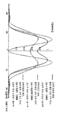
도 2에는 망막 물체 점 간 크로스토크의 원인인 점 확산 함수의 사이드 로브(side lobe) 간섭의 도면이 도시되어 있다. 상세히, 도 2는 에어(Airy)-함수를 사용하여 기술된 인접한 점 확산 함수의 중첩을 도시한다. 실선은 광학 시스템의 분해능 한계에서 인코히어런트 중첩을 나타내며, 이는 인간의 눈의 경우 1/60도 각도 간격과 동등하다. 도 2의 파선은 분해능 한계에서 2개의 점 확산 함수의 코히어런트 중첩을 나타낸다. 이 2개의 코히어런트 점 확산 함수 간의 상대적인 위상차는 제로이다. 두 점 사이의 중심에 존재하는 강도 감소의 백분율은 인코히어런트 경우와 동일하며, 이는 강도 분포의 중심의 좌측 및 우측 편에 존재하는 피크 강도의 약 75%이다. 점선은 분해능 한계에서 2개의 점 확산 함수의 코히어런트 중첩을 보여준다. 이 2개의 코히어런트 점 확산 함수 간의 상대적인 위상차는 π(Pi)이다. 이 경우 2개의 점 확산 함수 사이에 제로의 강도 값이 있다. 도 2는 코히어런트 경우에 상호 코히어런스 및 상호 위상 차가 인간의 눈의 망막에서 얻은 강도 분포의 정의에 있어 중요하다는 것을 보여준다.FIG. 2 shows a diagram of side lobe interference of the point spread function which is the cause of crosstalk between retinal object points. In particular, Figure 2 shows the overlap of adjacent point spread functions described using the Airy-function. The solid line represents an incoherent overlap at the resolution limit of the optical system, which is equivalent to a 1/60 degree angular interval for the human eye. The dashed line in Fig. 2 shows the coherent superposition of two point spread functions at the resolution limit. The relative phase difference between these two coherent point spread functions is zero. The percentage of intensity reduction present at the center between the two points is the same as for the incoherent case, which is about 75% of the peak intensity at the left and right sides of the center of the intensity distribution. The dotted line shows the coherent overlap of the two point spread functions at the resolution limit. The relative phase difference between these two coherent point spread functions is pi (Pi). In this case, there is an intensity value of zero between two point spread functions. Figure 2 shows that in the coherent case the mutual coherence and mutual phase difference is important in defining the intensity distribution obtained in the retina of the human eye.
3차원 물체 점을 나타내는 인접한 망막 점 확산 함수는 서로 간섭한다. 인접한 망막 점 확산 함수의 간섭을 방지 또는 제거하는 한 가지 방법은 생성된 회절 패턴의 사이드 로브를 감소시키거나(reduce) 약화시켜(diminish), 점 확산 함수의 외부 중첩 구역에서의 간섭을 감소시키는 것이다. 그러나, 일반적으로 망막 물체 점 간 크로스토크의 문제는 그러한 동작에 의해 해결되지 않는다. 시작으로서, 회절 패턴의 사이드 로브가 감소되어 물체 강도 분포를 달성한다. 코히어런트 점 확산 함수들이 함께 더 가깝게 이동하고 따라서 오버랩 영역을 확대하는 경우, 도입된 위상 시프트는 획득된 강도 분포를 정의한다. 예를 들어, 위상 시프팅 마스크에 사용되는 π(Pi)의 상대적 위상 시프트는 2개의 인접한 물체 점들 사이에 어두운 선을 생성하고 서로에게 인식된 상호 거리를 증가시킬 것이다. 이것은 도 2에 도시되어 있다. 2개의 인접 물체 점 사이의 어두운 선을 피하기 위해 π/2의 상호 위상차를 사용하는 것이 바람직하다. 이것은 최적화를 위한 시작 값으로만 사용될 수 있다는 것을 유의해야 한다. 이것은 또한 재구성된 물체 점 사이에 존재하는 무작위 위상 분포가 바람직하지 않음을 지적한다. π에 근접한 인접 위상차의 값은 재구성된 물체를 바라 보는 관찰자의 눈의 망막에 존재하는 화질을 감소시킨다.Adjacent retinal point spreading functions that represent three-dimensional object points interfere with each other. One way to prevent or eliminate the interference of adjacent retinal point spreading functions is to diminish or reduce the sidelobes of the resulting diffraction pattern to reduce interference in the outer overlap region of the point spread function . However, the problem of crosstalk between retinal object points in general is not solved by such an operation. As a start, the side lobe of the diffraction pattern is reduced to achieve an object intensity distribution. When the coherent point spreading functions move closer together and thus enlarge the overlap region, the introduced phase shift defines the obtained intensity distribution. For example, the relative phase shift of? (Pi) used in the phase shifting mask will create a dark line between two adjacent object points and increase the mutual distance recognized to each other. This is shown in FIG. It is preferable to use a mutual phase difference of pi / 2 to avoid dark lines between two adjacent object points. Note that this can only be used as a starting value for optimization. This also indicates that a random phase distribution present between reconstructed object points is undesirable. The value of the adjacent phase difference close to? reduces the image quality in the retina of the observer's eye looking at the reconstructed object.
본 발명에 따르면, 관찰자 평면 내의 가상 시야 윈도우(viewing window) 내의 상이한 위치들로부터 볼 수 있는 3차원 물체의 적당한 일정한 강도 분포를 가능하게 하기 위해, 망막 점 확산 함수 PSF의 임의 현저한 오버랩을 회피하여 회절 패턴의 사이드 로브의 형상을 최적화하고, 사이드 로브를 감소시켜 인접한 망막 점 확산 함수 PSFij의 상대적 위상차를 최적화하기 위해 상이한 접근법이 제공된다. 인접한 물체 점들 사이의 무작위 상대적 위상 시프트가 인코딩되는 경우, 사용된 위상 범위를 ±π/4 미만으로 제한하는 것이 바람직하다. 이는 또한 3x 또는 4x 1/60도의 상대적 각도 거리에 배치되는 물체 점에 대해서도 사용될 수 있으며, 이는 HD(high definition) 시야라고 불린다.In accordance with the present invention, any significant overlap of the retinal point spread function PSF is avoided to enable a suitable constant intensity distribution of a three-dimensional object visible from different positions within a virtual viewing window in the viewer plane, A different approach is provided to optimize the shape of the side lobe of the pattern and to reduce the side lobe to optimize the relative retardation of the adjacent retinal point spread function PSF ij . When a random relative phase shift between adjacent object points is encoded, it is desirable to limit the used phase range to less than +/- pi / 4. It can also be used for object points located at relative angular distances of 3x or
본 발명의 또 다른 바람직한 실시 예에서, 공간 광 변조기 디바이스에서 1차원 인코딩된 홀로그램 또는 2차원 인코딩된 홀로그램의 경우, 분리기는 컬러 필터 스트라이프 배열(arrangement), 바람직하게는 원색 필터 스트라이프 배열로서 설계될 수 있다는 것이 제공된다.In another preferred embodiment of the present invention, in the case of one-dimensionally encoded holograms or two-dimensionally encoded holograms in a spatial light modulator device, the separator may be designed as a color filter stripe arrangement, preferably a primary color filter stripe arrangement Is provided.
예를 들어 VPO(vertical parallax only)를 의미하는 1차원(1D) 인코딩을 사용하는 경우, 3차원 장면 또는 3차원 물체의 물체 점을 생성하기 위해 공간 광 변조기 디바이스의 상호 인코히어런트 열이 사용되어야 한다. 이것은 컬러 필터 스트라이프 배열을 사용하고, 또한 시간-순차적(time-sequential) 컬러 생성을 사용하여 실현될 수 있다.For example, when using one-dimensional (1D) encoding, which means vertical parallax only (VPO), mutual incoherent columns of spatial light modulator devices must be used to generate object points of a three- do. This can be realized using a color filter stripe arrangement and also using time-sequential color generation.
예를 들어 미세 추적을 위해 LC(liquid crystal)-편광 격자가 사용되는 경우, 상이한 컬러가 시간-순차적으로 디스플레이될 수 있다. 이는 또한 본 발명이 일반적으로 컬러 필터 스트라이프 또는 컬러 필터의 사용에 명시적으로 제한되지 않는다는 것을 의미한다.For example, when a liquid crystal (LC) -polarization grating is used for fine tracking, different colors can be displayed in a time-sequential manner. This also means that the present invention is not explicitly limited to the use of color filter stripes or color filters in general.
1/60도 각도 분해능 또는 각 도마다 60개의 물체 점과 동등한 HD(high definition) 분해능에 필요한 수보다 더 많은 공간 광 변조기 디바이스(SLM)의 1차원(1D) 인코딩된 스트라이프를 사용하는 것이 바람직하다. 이는 컬러 필터를 사용하여 실현할 수 있다. 그러나 어떤 경우에는 컬러 필터가 올바른 방법이 아닐 것이다. 컬러 필터를 사용하는 경우, 적어도 2개의 RGB(적색, 녹색, 청색) 필터 스트라이프 세트를 1/60 °의 수평 각도 범위 내에 배치해야 한다. 물체 점은 인터레이스 방식으로 재구성될 수 있다. 따라서, 복수의 물체 점들로 구성된 재구성된 장면을 관찰하는 관찰자의 눈의 망막상에서 재구성된 인접한 물체 점들은 서로 인코히어런트이다.It is desirable to use a one-dimensional (1D) encoded stripe of spatial light modulator device (SLM) greater than the required number of 1/60 degree angular resolution or HD (high definition) resolution equivalent to 60 object points per degree . This can be realized by using a color filter. In some cases, however, the color filter may not be the right way. When using a color filter, at least two RGB (red, green, blue) filter stripe sets must be placed within a horizontal angle range of 1/60 degrees. Object points can be reconstructed in an interlaced manner. Thus, adjacent object points reconstructed on the retina of the observer's eye observing the reconstructed scene consisting of a plurality of object points are incoherent to each other.
바람직하게는, 공간 광 변조기 디바이스의 각각의 주요(primary) 서브-홀로그램 또는 초기 픽셀은 적어도 2개의 서브 세트를 나타내고 적어도 두개의 웨이브 필드를 생성하는 적어도 2개의 정의된 부분으로 세분될 수 있다. 다시 말해서, 주요 서브-홀로그램을 포함하는 공간 광 변조기 디바이스 상의 구역(zone) 또는 영역은 적어도 2개의 서브 세트 또는 정의된 부분으로 세분될 수 있다. 컬러 필터 스트라이프의 삼중선(triplet)(RGB)을 각 서브 세트에 지정할 수 있다. 보다 바람직하게는 광 변조기 디바이스의 주요 서브-홀로그램 또는 단일 초기 픽셀에 할당된 컬러 스트라이프의 밀도를 예를 들어, 픽셀 당 3개의 컬러 스트라이프의 원래 밀도의 3배(3x) 또는 4배(4x)로 증가시키는 것이다. 이것은 각각의 주요 서브-홀로그램 또는 각각의 초기 픽셀이 3개 또는 4개의 정의된 부분, 소위 3개 또는 4개의 서브 세트로 세분화되는 것을 의미하고, 컬러 필터 스트라이프의 삼중선(RGB)이 각 정의된 부분 또는 서브 세트로 할당된다. Preferably, each primary sub-hologram or initial pixel of the spatial light modulator device is subdivided into at least two defined portions representing at least two subsets and producing at least two wave fields. In other words, the zone or region on the spatial light modulator device that contains the primary sub-hologram may be subdivided into at least two subsets or defined portions. The triplet (RGB) of the color filter stripe can be assigned to each subset. More preferably, the density of the color stripe assigned to the primary sub-hologram or single initial pixel of the optical modulator device is reduced to, for example, three times (3x) or four times (4x) the original density of three color stripes per pixel . This means that each primary sub-hologram or each initial pixel is subdivided into three or four defined portions, so-called three or four subsets, and the triplet (RGB) of the color filter stripe is defined by each defined ≪ / RTI >
본 발명의 또 다른 바람직한 실시 예에서, 컬러 필터 스트라이프 배열은 흡수형 염료 기반 필터 배열 또는 유전체 필터 배열인데, 이는 초기 픽셀 또는 주요 서브-홀로그램의 서브 세트에 할당되도록 구조화되는 것이 제공될 수 있다.In another preferred embodiment of the present invention, the color filter stripe arrangement is an absorption dye-based filter arrangement or dielectric filter arrangement, which may be provided to be structured to be assigned to an initial pixel or a subset of the main sub-holograms.
컬러 필터 스트라이프 배열 또는 일반적으로 컬러 필터는 복소 변조 웨이브 필드를 제공하는 SLM에 필수인 프레임 속도를 줄이기 위해 사용될 수 있다. 바람직하게는 SLM 픽셀에 정렬된 구조의 흡수형 염료 기반 필터 어레이를 사용하는 것이 가능하다. 현대 코팅 기술은 또한 노치 필터를 스트라이프 배열로 적용하는 것을 가능하게 한다. 이것은 컬러 스트라이프가 원색 RGB(적색, 녹색, 청색) 중 1개만을 투과하면서 2개를 반사할 수 있다는 것을 의미한다. 이는 0.9보다 큰 투과율로 행해질 수 있지만, 이러한 특정 컬러 스트라이프의 다른 2개의 요구되지 않는 파장은 1에 가까운 계수로 반사된다.A color filter stripe arrangement or color filter in general can be used to reduce the frame rate required by the SLM to provide a complex modulated wave field. It is possible to use an absorptive dye-based filter array having a structure that is preferably aligned with the SLM pixels. Modern coating techniques also make it possible to apply a notch filter in a stripe arrangement. This means that the color stripe can reflect two while transmitting only one of the primary colors RGB (red, green, blue). This can be done with a transmittance greater than 0.9, but the other two undesired wavelengths of this particular color stripe are reflected with coefficients close to unity.
유리하게는, 인코딩될 2차원(2D) 홀로그램의 경우, 주요 서브-홀로그램 또는 초기 픽셀의 적어도 2개의 정의된 부분은 픽셀이 수평 또는 수직으로 분리되는 2개의 절반을 형성한다는 것이 제공될 수 있다.Advantageously, in the case of a two-dimensional (2D) hologram to be encoded, it can be provided that at least two defined portions of the main sub-hologram or initial pixel form two halves, horizontally or vertically separated.
공간 광 변조기 디바이스(SLM)는 변조 요소로서 픽셀을 갖는다. 픽셀은 직사각형, 정사각형 또는 원형 또는 육각형 또는 임의 다른 형상을 가질 수 있다. 이러한 SLM의 픽셀은 적어도 2개의 정의된 부분으로 분할될 수 있다. 픽셀의 이러한 2개의 정의된 부분은 2개의 절반을 형성할 수 있다. 이것은 우측 및 좌측 부분/절반/서브 세트 또는 상부 및 하부 부분/절반/서브 세트를 형성하기 위하여 픽셀을 수평으로 또는 수직으로 분리할 수 있음을 의미한다. 본질적으로, 픽셀의 두 부분 또는 서브 세트가 SLM 외부에서 생성된다. SLM의 우측 서브 세트 및 SLM의 좌측 서브 세트 또는 하부 서브 세트 및 상부 서브 세트는 SLM의 푸리에 평면에서 등가 강도 분포를 생성한다. 다시 말해서, 우측/상부 서브 세트에 대한 진폭 분포의 푸리에 평면에서의 강도 분포 및 좌측/하부 서브 세트에 대한 진폭 분포는 SLM에서 일정 위상이 사용되는 경우 동일하다. 두 가지 푸리에 변환의 위상 값은 이 설명과 관련이 없다. 따라서, SLM의 2개의 서브 세트의 인코히어런트 중첩이 진폭 분포로서 사용된다.The spatial light modulator device (SLM) has pixels as modulation elements. The pixel may have a rectangular, square or circular or hexagonal shape or any other shape. The pixels of such an SLM may be divided into at least two defined portions. These two defined portions of the pixel can form two halves. This means that the pixels can be horizontally or vertically separated to form the right and left part / half / subset or the top and bottom part / half / subset. Essentially, two portions or subsets of pixels are generated outside the SLM. The right subset of SLMs and the left subset or lower subset and upper subset of SLMs generate an equivalent intensity distribution at the Fourier plane of the SLM. In other words, the intensity distribution in the Fourier plane of the amplitude distribution for the right / upper subset and the amplitude distribution for the left / bottom subset are the same when a certain phase is used in the SLM. The phase values of the two Fourier transforms are irrelevant to this description. Thus, the inchoherent superposition of the two subsets of the SLM is used as the amplitude distribution.
또한, 분리기는 바람직하게는 정의된 편광 상태를 갖는 광을 2개의 패턴화된 광 서브 세트로 변환시키기 위해 패턴화된 리타더(patterned retarder)의 배열로서 설계된다는 것이 유리하게 제공될 수 있다.It may also be advantageously provided that the separator is preferably designed as an array of patterned retarders for converting light having a defined polarization state into two patterned light subsets.
패턴화된 리타더의 배열은 예를 들어 선형 편광 상태일 수 있는 초기 편광 상태를 2개의 패턴화된 서브 세트로 변환하기 위해 제공된다. 2개의 패턴화된 서브 세트는 직교 편광 상태를 갖는다. 예를 들어, SLM의 픽셀의 주요 애퍼처, 예를 들어, 정사각형 형상의 픽셀 애퍼처 또는 임의 다른 적합한 형상은 2개의 부분으로 분할된다. 이것은 SLM의 초기 픽셀 카운트가 두 배로 증가하므로 SLM의 초기 픽셀 밀도도 두 배가 됨을 의미한다. 초기 픽셀 또는 주요 서브-홀로그램의 2개의 서브 세트에는 정의된 패턴화된 리타더가 제공된다. 제1 서브 세트에는 a + π/4 패턴화된 리타더가 제공될 수 있으며, 제2 서브 세트에는 a - π/4 패턴화된 리타더가 제공될 수 있다. 각각의 픽셀의 이들 2개의 서브 세트를 포함하는 SLM이 선형 편광된 광으로 조명되면, SLM의 출사 평면에서, 상이한 패턴화된 리타더를 운반하는 SLM의 각각의 픽셀의 2개의 서브 세트와 관련된 2개의 직교 편광된 웨이브 필드가 존재할 것이다. 다시 말해서, 패턴화된 리타더의 배열은 픽셀의 평면 내에 제공될 수 있고, 공간 광 변조기 디바이스의 픽셀에 할당될 수 있으며, 여기서 픽셀의 각 정의된 부분 또는 픽셀의 각 서브 세트에는 패턴화된 리타더의 배열의 정의된 패턴화된 리타더가 제공된다. 픽셀의 적어도 2개의 정의된 부분은 직교 편광을 제공하는 상이한 패턴화된 리타더를 갖는다. 유리하게는, 수평 방향으로만 또는 수직 방향으로만 보여지는 인접한 패턴화된 리타더의 편광 방향은 서로 직교한다.The arrangement of patterned retarders is provided, for example, to convert an initial polarization state, which may be a linear polarization state, into two patterned subsets. The two patterned subsets have an orthogonal polarization state. For example, the main aperture of a pixel of the SLM, e.g., a square-shaped pixel aperture or any other suitable shape, is divided into two parts. This means that the initial pixel count of the SLM doubles, doubling the original pixel density of the SLM as well. The initial pixel or two subsets of the main sub-hologram are provided with a defined patterned retarder. The first subset may be provided with a + π / 4 patterned retarders, and the second subset may be provided with a - π / 4 patterned retarders. When the SLM comprising these two subsets of each pixel is illuminated with linearly polarized light, at the exit plane of the SLM, the two associated sub-sets of each pixel of the SLM carrying different patterned retarders, There will be orthogonally polarized wave fields. In other words, the arrangement of the patterned retarders can be provided in the plane of the pixel and can be assigned to the pixels of the spatial light modulator device, where each defined portion of the pixel or each subset of pixels has a patterned Rita A defined patterned retarder of the array of the dots is provided. At least two defined portions of the pixels have different patterned retarders that provide orthogonal polarization. Advantageously, the polarization directions of adjacent patterned retarders, which are only seen in the horizontal direction or only in the vertical direction, are orthogonal to one another.
본 발명의 다른 실시 예에서, 패턴화된 리타더의 배열은 픽셀의 적어도 2개의 정의된 부분에 할당된 패턴화된 편광 필터의 배열로서 설계된다는 것이 제공될 수 있다. 이것은 픽셀의 하나의 서브 세트에 대한 수평으로 배향된 전기장의 투과 및 픽셀의 다른 서브 세트에 대한 수직으로 배향된 전기장의 투과를 허용한다. 따라서 패턴화된 편광 필터들의 배열은 스트라이프 패턴을 제공하며, 스트라이프 패턴은 투과된 편광 상태의 교대하는 방향을 갖는다.In another embodiment of the present invention, it can be provided that the arrangement of the patterned retarders is designed as an array of patterned polarizing filters assigned to at least two defined portions of pixels. This allows the transmission of a horizontally oriented electric field for one subset of pixels and the transmission of a vertically oriented electric field to another subset of pixels. The array of patterned polarizing filters thus provides a stripe pattern, the stripe pattern having an alternating direction of the transmitted polarization state.
본 발명에 따라, 패턴화된 편광 필터들의 배열은 수직 방향(y 방향) 및 수평 방향(x 방향)을 따라 고정된 패턴인 직교 편광 상태들의 패턴을 제공할 수 있고, 깊이 방향(z 방향)을 따라 패턴은 반전되어 교대로 사용된다는 것이 제공될 수 있다.According to the present invention, the arrangement of patterned polarizing filters can provide a pattern of orthogonal polarization states that is a fixed pattern along the vertical direction (y direction) and the horizontal direction (x direction) It can be provided that the pattern is inverted and used alternately.
물체 점은 공간의 상이한 그리드에서 생성될 수 있다. 3차원 공간에서 물체의 깊이 평면은 교대하는 할당 패턴을 가질 수 있다. 이것은 동일한 x 좌표 및 동일한 y 좌표를 갖지만 인접한 깊이 평면에 배치되는 물체 점이 바람직하게는 직교 편광 상태를 가질 수 있다는 것을 의미한다. 즉, 편광 상태를 나타내는 물체의 깊이 평면에 대한 할당 패턴은 교대로 z 좌표를 따라 사용될 수 있다. 따라서, 편광 상태는 인접한 z 평면에 대해 반전된다. 그러나 가장 간단한 방법은 수직 방향과 수평 방향을 따라 고정 패턴을 사용하고, 관찰자와의 거리 또는 물체가 분할되는 상이한 z 평면들의 거리인 z 좌표(깊이 좌표)를 따라 교대로 반전시키는 것일 수 있다.Object points can be generated in different grids of space. The depth plane of an object in a three-dimensional space may have an alternate assignment pattern. This means that an object point having the same x-coordinate and the same y-coordinate but placed in adjacent depth planes can preferably have an orthogonal polarization state. That is, the allocation pattern for the depth plane of the object exhibiting the polarization state can be used alternately along the z coordinate. Thus, the polarization state is inverted with respect to the adjacent z plane. However, the simplest method could be to use a fixed pattern along the vertical and horizontal directions and alternately invert along the z coordinate (depth coordinate), the distance to the observer or the distance of the different z planes where the object is divided.
본 발명의 또 다른 유리한 실시 예에서, 디스플레이 디바이스는 광의 전파 방향에서 보았을 때, 공간 광 변조기 디바이스 뒤에 배치되어, 2개의 상호 인코히어런트 웨이브 필드를 포함하는 단일 출사(exit) 편광 상태를 갖는 광을 제공하는 비-패턴화된 리타더를 포함하는 것이 제공될 수 있다.In a further advantageous embodiment of the present invention, the display device is arranged behind the spatial light modulator device when viewed in the direction of propagation of light, such that light having a single exit polarization state comprising two mutually incoherent wave fields Lt; RTI ID = 0.0 > non-patterned retarder. ≪ / RTI >
바람직하게는 편광 필터로서 설계될 수 있는 SLM 뒤에 배치된 비-패턴화된 리타더를 추가하는 것은, 2개의 상호 인코히어런트 웨이브 필드를 포함하는 광의 단일 출사 편광 상태를 제공한다. 이 2개의 상호 인코히어런트 웨이브 필드는 3차원(3D) 물체 또는 장면의 일부를 포함하거나 운반한다.Adding a non-patterned retarder, preferably placed behind the SLM, which can be designed as a polarization filter, provides a single outgoing polarization state of light comprising two mutually incoherent wave fields. These two mutually incoherent wave fields contain or carry a part of a three-dimensional (3D) object or scene.
또한, 본 발명에 따른 디스플레이 디바이스는 물체 점을 나타내는 서브-홀로그램의 계산에서 정의된 각도 범위 내에서 물체 점을 측 방향으로 시프트하기 위해 쐐기 함수(wedge function)가 사용되는 방식으로 제공될 수 있다.The display device according to the present invention may also be provided in such a way that a wedge function is used to laterally shift the object point within the angular range defined in the calculation of the sub-hologram representing the object point.
2개의 직교 편광을 실현하기 위해, 서브-홀로그램에서 쐐기 함수를 인코딩할 수 있는데, 이는 관찰자 평면에서 시야 윈도우에 걸치는 각도 범위 내에서 물체 점을 측 방향으로 시프트할 수 있다. 홀로그램을 SLM으로 2차원(2D) 인코딩하기 위해, 쐐기 함수의 인코딩은 수평 방향뿐만 아니라 수직 방향을 따라 수행될 수 있다. 다시 말해서, 예를 들어, 픽셀의 정방형(quadratic)/정사각형(square) 영역의 좌측 및 우측 분리는 인접한 직교 편광된 망막 점 확산 함수의 좌측 및 우측 분리인 수평 분리를 생성할 수 있다. 픽셀 영역의 상부 및 하부 분리는 인접한 직교 편광된 망막 점 확산 함수의 상부 및 하부 분리인 수직 분리를 생성할 수 있다. 이는 또한 픽셀의 직사각형 형상 또는 임의 다른 적절한 픽셀 형상에 적용될 수 있다.To realize two orthogonal polarizations, the wedge function can be encoded in the sub-hologram, which can laterally shift the object point within the angular range over the viewing window in the observer plane. In order to two-dimensionally (2D) encode the hologram into the SLM, the encoding of the wedge function may be performed along the vertical direction as well as the horizontal direction. In other words, for example, the left and right separation of a quadratic / square region of a pixel can produce horizontal separation, which is the left and right separation of adjacent orthogonally polarized retinal point spreading functions. The top and bottom separation of the pixel region may produce vertical separation, which is the upper and lower separation of the adjacent orthogonally polarized retinal point spreading function. It can also be applied to the rectangular shape of the pixel or any other suitable pixel shape.
홀로그램의 1차원(1D) 인코딩과는 대조적으로, 홀로그램의 2차원(2D) 인코딩은 임의 모양의 2차원 위상 쐐기 함수의 실현 가능성을 제공한다. 잠재적인 2차원 쐐기 분포의 서브 세트만 필요하다. 즉, 쐐기 함수는 임의 형상의 2차원 위상 쐐기 함수일 수 있다.In contrast to the one-dimensional (1D) encoding of a hologram, the two-dimensional (2D) encoding of the hologram provides the feasibility of a two-dimensional phase wedge function of arbitrary shape. Only a subset of the potential two-dimensional wedge distribution is needed. That is, the wedge function may be a two-dimensional phase wedge function of arbitrary shape.
본 발명의 또 다른 실시 예에서, 개별 물체 점에 대한 파면의 복소수 값의 상대적 위상은, 물체의 인접한 물체 점을 나타내는 점 확산 함수에 의해 생성되는 관찰자의 눈에서의 총 강도 분포와 타겟 강도 분포 사이의 차이가 최소화되는 방식으로 정의된다. 망막 상의 물체 점의 계산을 통해 이를 수행할 수 있다. 너무 많은 강도가 있는 영역에서는 망막 상의 강도가 감소되고 강도가 너무 낮은 영역에서는 강도가 증가된다. 다시 말해서, 강도의 실제 분포는 강도의 타겟 분포에 적응된다.In another embodiment of the present invention, the relative phase of the complex value of the wavefront for an individual object point is determined by the difference between the total intensity distribution in the eye of the observer, produced by the point spread function representing an object point adjacent to the object, Is minimized. This can be done by calculating the object point on the retina. In regions with too much intensity, intensity on the retina decreases and intensity increases in regions where intensity is too low. In other words, the actual distribution of intensity is adapted to the target distribution of intensity.
물체 또는 장면의 개별 물체 점의 상대적 위상, 즉 상호 위상차는 "관찰자의 눈의 망막의 평면에서 타겟 강도 분포(should be/target intensity distribution in the plane of the retina of the eye of the observer) I(X, Y)_retina" 및 "눈의 망막의 평면에서 총 강도 분포(is/total intensity distribution in the plane of the retina of the eye) I(X, Y)_retina"의 차이를 최소화하는 방식으로 선택될 수 있다. 분석 모델을 사용하여 최적의 위상과 강도를 직접 계산할 수 있다. 이러한 분석 모델을 사용할 수 없는 경우 다음 절차를 사용할 수 있다. 망막 물체 점 간 크로스토크가 아직 고려되지 않은 최적화된 이미지는 예를 들어, WPM(wave propagation method)을 사용하거나 프레넬 변환(Fresnel transformation)을 사용함으로써 모델에서 망막으로 전파될 수 있다. 다음으로, 타겟 강도 분포와 총 강도 분포 사이의 편차가 결정된다. 다음 단계에서, 개별 물체 점들의 위상은 편차가 감소되는 방식으로 수정되거나 달라질 수 있다. 절차는 반복적일 수 있다. 이것은 공간 광 변조기의 최적 복소수 값을 계산하는 동안 추가 반복에 관한 것이다.The relative phase, or mutual phase difference, of an object or an individual object point in a scene is defined as the ratio of the target intensity distribution I (X (x)) to the target intensity distribution in the plane of the retina of the observer's eye , Y) _retina "and" I (X, Y) _retina "of the total intensity distribution in the plane of the retina of the eye (is / total intensity distribution in the plane of the retina of the eye) have. The analytical model can be used to directly calculate the optimal phase and intensity. If you can not use this analytical model, you can use the following procedure. Optimized images for which retinal object point crosstalk has not yet been considered can be propagated from the model to the retina, for example, by using the wave propagation method (WPM) or by using a Fresnel transformation. Next, the deviation between the target intensity distribution and the total intensity distribution is determined. In the next step, the phase of the individual object points may be modified or changed in such a way that the deviation is reduced. The procedure can be iterative. This relates to additional iterations while calculating the optimum complex value of the spatial light modulator.
개개의 물체 점에 대한 파면의 복소수 값의 진폭은, 물체의 인접한 물체 점을 나타내는 점 확산 함수에 의해 생성된 관찰자의 눈에서의 총 강도 분포와 타겟 강도 분포의 차이가 최소화되는 식으로 유리하게 정의될 수 있다. 망막 상의 물체 점의 계산을 통해 이를 수행할 수 있다. 너무 많은 강도가 있는 곳에서는 망막 상의 강도가 감소되고 강도가 너무 낮은 곳에서는 강도가 증가된다. 다시 말해서, 강도의 실제 분포는 강도의 타겟 분포에 적응된다.The amplitude of the complex value of the wavefront for an individual object point is advantageously defined in such a way that the difference between the total intensity distribution at the observer's eye generated by the point spread function representing the object's adjacent object points and the target intensity distribution is minimized . This can be done by calculating the object point on the retina. Where there is too much strength, the strength of the retina is reduced and the strength is increased where the strength is too low. In other words, the actual distribution of intensity is adapted to the target distribution of intensity.
각 물체 점의 파면의 복소수 값의 강도, 즉 진폭은 관찰자의 눈의 망막 평면에서 "관찰자의 눈의 망막의 평면에서 타겟 강도 분포 I(X, Y)_retina" 및 "눈의 망막의 평면에서 총 강도 분포 I(X, Y)_retina"의 차이를 최소화하는 방식으로 선택될 수 있다. 분석 모델을 사용하여 최적의 위상과 강도를 직접 계산할 수 있다. 이러한 분석 모델을 사용할 수 없는 경우 다음 절차를 사용할 수 있다. 망막 물체 점 간 크로스토크가 아직 고려되지 않은 최적화된 이미지는 예를 들어, WPM(wave propagation method)을 사용하거나 프레넬 변환(Fresnel transformation)을 사용함으로써 모델에서 망막으로 전파될 수 있다. 다음으로, 타겟 강도 분포와 총 강도 분포 사이의 편차가 결정된다. 다음 단계에서, 개별 물체 점들의 진폭은 편차가 감소되는 방식으로 수정될 수 있다. 절차는 반복적일 수 있다. 이것은 공간 광 변조기의 최적 복소수 값을 계산하는 동안 추가 반복에 관한 것이다.The intensity, or amplitude, of the complex value of the wavefront of each object point is calculated as the sum of the target intensity distribution I (X, Y) _retina in the retina plane of the observer's eye and the total Intensity distribution I (X, Y) _retina ". The analytical model can be used to directly calculate the optimal phase and intensity. If you can not use this analytical model, you can use the following procedure. Optimized images for which retinal object point crosstalk has not yet been considered can be propagated from the model to the retina, for example, by using the wave propagation method (WPM) or by using a Fresnel transformation. Next, the deviation between the target intensity distribution and the total intensity distribution is determined. In the next step, the amplitude of the individual object points can be modified in such a way that the deviation is reduced. The procedure can be iterative. This relates to additional iterations while calculating the optimum complex value of the spatial light modulator.
다시 말해서, 반복 최적화를 선택할 수 있다. 2개의 물체 점들 사이의 상대적인 페이징(phasing)이 타겟 강도 분포에 더 가깝게 도달하기 위하여 어느 방향으로 시프트되어야 하는지는 인코딩될 이미지 콘텐츠에 의존한다. 중첩은 분석적이다. 이 방법으로 한 점과 다른 점들도 수학적으로 생성될 수 있다. 한 점에 이웃하는 점을 분석적으로 배치할 수 있다. 즉, 이미지는 상기 이미지의 에지를 따라 생성될 수 있다.In other words, repeat optimization can be chosen. The direction in which the relative phasing between two object points should be shifted in order to arrive closer to the target intensity distribution depends on the image content to be encoded. The overlap is analytical. In this way, one point and the other points can also be mathematically generated. Neighboring points on one point can be analytically placed. That is, an image may be generated along the edge of the image.
대안적으로 초기 인코딩을 사용할 수도 있고, 이 초기 인코딩은 그 후 반복적으로 최적화된다. 이 과정에서 타겟 강도 분포 또는 타겟 이미지와의 편차 또는 차이를 확인해야 한다. 임계 값이 반복을 중지시키기 위해 제공된다.Alternatively, an initial encoding may be used, and this initial encoding is then repeatedly optimized. In this process, the deviation or difference between the target intensity distribution or the target image should be confirmed. A threshold value is provided to stop the repetition.
또한, 이는 아포다이제이션 프로파일 또는 아포다이제이션 함수를 제공하는 것이 유리하다. 아포다이제이션 프로파일은 공간 광 변조기 디바이스의 픽셀의 평면에 제공되어 물체의 개개의 물체 점들의 아포다이즈된 서브-홀로그램을 달성할 수 있다.It is also advantageous to provide an apodization profile or an apodization function. The apodization profile may be provided in the plane of the pixels of the spatial light modulator device to achieve the apodized sub-hologram of the individual object points of the object.
적당히 큰(예를 들어, ≤ HD/2(최대 분해능의 절반)) 물체 점의 경우, 물체 점은 "타겟 강도 분포(should be/target intensity distribution) I(X, Y)_retina" 및 "총 강도 분포(is/total intensity distribution) I(X, Y)_retina"의 차이를 최소화하는 방식으로 수정될 수 있다. 이것은 눈의 점 확산 함수에 의해 픽업될 평면 내에 형성되는 물체 점들을 나타내는 아포다이즈된 서브-홀로그램에 의해 수행될 수 있다. 관찰자가 보고 있는 모든 물체 점이 SLM에 의해 생성된다. 따라서, SLM의 서브-홀로그램에 존재하는 복소수 값 강도 분포는 감소된 사이드 로브를 갖는 점 확산 함수를 생성하기 위해 사용될 수 있다. 이것은 예를 들어. 관찰자의 눈의 망막에 점 확산 함수를 생성할 수 있는 아포다이즈된 서브-홀로그램을 사용하는 것을 의미한다. 이러한 점 확산 함수는 에어리(Airy) 분포이면 안 되고, 사이드 로브가 없는 가우스(Gauss) 분포여야 한다. 물체 점들의 강도 분포에서의 사이드 로브는 "타겟 강도 분포 I(X, Y)_retina" 및 "총 강도 분포 I(X, Y)_retina"의 차이를 최소화하는 방식으로 억제되거나 형상화에서 심지어 영향을 받을 수 있다. 그러나, 중첩시에 망막 상의 타겟 강도 분포에 대한 더 낮은 편차가 달성될 수 있다면, 사이드 로브는 또한 증가될 수 있다.For object points that are moderately large (e.g., ≤ HD / 2 (half the maximum resolution)), the object points are defined as "should be / target intensity distribution I (X, Y) _retina" Can be modified in such a way as to minimize the difference between the distribution (is / total intensity distribution) I (X, Y) _retina ". This can be done by apodized sub-holograms representing object points formed in the plane to be picked up by the point spread function of the eye. All object points that the observer is viewing are generated by the SLM. Hence, the complex intensity intensity distribution present in the sub-hologram of the SLM can be used to generate a point spread function with reduced side lobes. This is an example. Quot; means using an apodized sub-hologram capable of generating a point spread function at the retina of the observer's eye. This point spread function should not be an Airy distribution and should be a Gaussian distribution without side lobes. The side lobes in the intensity distribution of object points are suppressed or even influenced in the shaping in such a way as to minimize the difference of the "target intensity distribution I (X, Y) _retina" and "total intensity distribution I (X, Y) . However, if lower deviations for the target intensity distribution on the retina at the time of superposition can be achieved, the side lobe can also be increased.
이 방법은 적당히 큰 물체 점에 더 잘 적용될 수 있다. 그러나, 해당 애플리케이션에만 국한되지는 않는다. 사이드 로브의 강도의 변화는 매우 작은 물체 점 및 그에 따른 큰 서브-홀로그램에 대해 그다지 효율적이지 못하다.This method can be applied better to moderately large object points. However, it is not limited to the application. The variation of the intensity of the side lobes is not very efficient for very small object points and thus large sub-holograms.
서브-홀로그램에 대한 아포다이제이션 함수는 a(x, y)_SLM(SLM 평면에서의 아포다이제이션 함수) 및 phase(x, y)_SLM(SLM 평면에서의 아포다이제이션 함수)일 수 있고, 이는 c(x, y)_SLM(SLM 평면에서의 아포다이제이션 함수)을 의미한다. 따라서 SLM 평면 내에서 사용되는 아포다이제이션 함수는 복소수 값을 가질 수 있다.The apodization function for the sub-hologram may be a (x, y) SLM (apodization function in the SLM plane) and phase (x, y) SLM (apodization function in the SLM plane) c (x, y) _SLM (apodization function in the SLM plane). Thus, the apodization function used in the SLM plane may have a complex value.
본 발명의 다른 실시 예에서, SLM의 서브-홀로그램은 그 형상이 수정 가능하다는 것이 제공될 수 있다.In another embodiment of the present invention, the sub-hologram of the SLM can be provided that its shape is modifiable.
SLM의 서브-홀로그램은 임의 형상을 가질 수 있다. 서브-홀로그램의 외형은 다양할 수 있다. 이러한 파라미터의 변화는 개개의 물체 점들의 망막 점 확산 함수의 모양을 변화시킨다. 예를 들어, 원형 또는 정방형/정사각형 모양이 사용될 수 있고 다른 모든 실용적인 형태도 사용될 수 있다. 특히, 2차원(2D) 인코딩의 경우, 서브-홀로그램의 수정된 형상을 사용함으로써 물체 점들의 형상화가 사용될 수 있다. 서브-홀로그램의 형상은 물체 점에 따라 적응될 수 있다. 적응된 형태는 고정된 원형 또는 정방형 모양에만 사용할 수 있는 c(x, y)_SLM과 관련된다. 문자 "c"는 그것이 복소수 값과 관련이 있음을 의미한다.The sub-hologram of the SLM may have any shape. The appearance of the sub-hologram may vary. This change in parameters changes the shape of the retinal point spread function of individual object points. For example, circular or square / square shapes may be used and all other practical shapes may be used. In particular, in the case of two-dimensional (2D) encoding, the shaping of object points can be used by using the modified shape of the sub-hologram. The shape of the sub-hologram can be adapted to the object point. The adapted form is associated with c (x, y) _SLM, which can only be used in fixed circular or square shapes. The letter "c" means that it is associated with a complex number value.
바람직하게는, 관찰자의 눈에 제공된 점 확산 함수의 고정된 미리 정의된 그리드가 사용되는 것이 제공될 수 있다.Advantageously, a fixed predefined grid of the point spread function provided to the observer's eye may be used.
점 확산 함수 PSFij의 고정 그리드는 물체 점에 의해 생성된 강도 분포에서 사이드 로브를 최적화하기 위해 사용될 수 있다. 점 확산 함수의 이러한 고정된 그리드는 점 확산 함수 PSFij의 상대적 위상차 및 강도를 최적화하는 데에도 사용될 수 있다. 이러한 최적화로, 재구성된 망막 이미지가 획득될 수 있는데, 이는 3차원(3D) 장면의 타겟 망막 이미지에 매우 가깝다. 점 확산 함수 PSFij에 관한 접미사 ij는 2차원 그리드의 점를 나타내는 인덱스이며, 바람직하게는 망막 수용체의 2차원 구형 곡선에 배치된 점이다.The fixed grid of the point spread function PSF ij can be used to optimize the side lobe in the intensity distribution produced by the object point. This fixed grid of the point spread function can also be used to optimize the relative phase difference and intensity of the point spread function PSF ij . With this optimization, a reconstructed retinal image can be obtained, which is very close to the target retinal image in a three-dimensional (3D) scene. The suffix ij with respect to the point spread function PSF ij is an index indicating the point of the two-dimensional grid, preferably a point arranged on a two-dimensional spherical curve of the retinal receptor.
바람직하게는 와이어 그리드 편광자 구조를 사용함으로써 조명 유닛이 2개의 직교 편광된 웨이브 필드를 방출하는 방식으로 적응될 수 있다는 것이 추가로 제공될 수 있다.It can be further provided that the illumination unit can be adapted in such a way that it preferably emits two orthogonally polarized wave fields by using a wire grid polarizer structure.
조명 유닛은 2개의 직교 편광된 웨이브 필드를 방출하기 위한 수단을 포함할 수 있거나 이를 위해 적응될 수 있다. 바람직하게는, 그러한 수단은 예를 들어, 와이어 그리드 편광자 구조 또는 와이어 그리드 편광자, 바람직하게는 2차원 와이어 그리드 편광자 구조일 수 있다. 와이어 그리드 편광자 구조는 조명 유닛에 제공된 2개의 미러로 된 미러로서 구현될 수 있으며, 이들은 조명 유닛의 적어도 하나의 광원의 공진기의 단부에서 사용된다. 적어도 하나의 광원은 예를 들어, 레이저 또는 레이저 다이오드일 수 있다. 이 특별한 와이어 그리드 편광자 구조의 주기는 일반적으로 π/2n보다 작고, 여기서 π는 레이저(레이저는 사용된 광원에 대해 이 맥락에서 사용됨. 즉, 그것은 또한 레이저 다이오드 또는 LED일 수도 있음) 파장이고, n은 와이어 그리드 편광자의 기판/구조의 상응하는 굴절률이다. 2개의 선형 직교 편광 상태는 와이어 그리드 편광자 구조를 사용하여 최대 반사율을 가지며, 반사율은 1(100 %)에 가깝다. 금속의 2차원 스트라이프 와이어 그리드 편광자 구조는 유전체 층 스택을 추가함으로써 그 반사율을 향상시킬 수 있다. 이러한 2차원 와이어 그리드 편광자 구조는 또한 조명 유닛에서 사용될 수 있다. 예를 들어, 와이어 그리드 편광자 구조 또는 다른 종류의 미러가 2개의 직교 선형 출사 편광 상태를 제공하기 위하여 조명 유닛의 광원 캐비티의 단부에서 사용될 수 있다. The illumination unit may comprise or be adapted for the means for emitting two orthogonally polarized wave fields. Preferably, such means may be, for example, a wire grid polarizer structure or a wire grid polarizer, preferably a two-dimensional wire grid polarizer structure. The wire grid polarizer structure may be implemented as a mirror of two mirrors provided in the illumination unit, which are used at the end of the resonator of at least one light source of the illumination unit. The at least one light source may be, for example, a laser or a laser diode. The period of this particular wire grid polarizer structure is generally less than π / 2n, where π is the wavelength of the laser (the laser is used in this context for the light source used, ie it may also be a laser diode or LED) Is the corresponding refractive index of the substrate / structure of the wire grid polarizer. The two linear orthogonal polarization states have maximum reflectivity using a wire grid polarizer structure, and the reflectance is close to 1 (100%). The two-dimensional stripe wire grid polarizer structure of the metal can improve its reflectivity by adding a dielectric layer stack. This two-dimensional wire grid polarizer structure can also be used in a lighting unit. For example, a wire grid polarizer structure or other kind of mirror may be used at the end of the light source cavity of the illumination unit to provide two orthogonal linear exit polarization states.
조명 유닛은 웨이브 필드를 생성하도록 제공된 적어도 하나의 광원, 바람직하게는 레이저 또는 레이저 다이오드를 포함할 수 있다. 조명 유닛은 원색 당 적어도 하나의 광원을 포함할 수 있다. 조명 유닛이 스트라이프와 같은 광원 배열을 포함하는 것이 또한 제공될 수 있다. The illumination unit may include at least one light source, preferably a laser or laser diode, provided to generate the wave field. The illumination unit may include at least one light source per primary color. It may also be provided that the lighting unit comprises a light source arrangement such as a stripe.
바람직하게는, 원색 RGB(적색, 녹색, 청색)마다 적어도 2개의 상호 인코히어런트 광원이 제공될 수 있다.Preferably, at least two mutually incoherent light sources may be provided for each primary color RGB (red, green, blue).
본 발명에 따르면, 공간 광 변조기 디바이스는 코히어런트 방향을 따라 ≤1/60도이고 인코히어런트 방향을 따라 0.5 내지 1도인 평면파(plane wave)들의 각 스펙트럼으로 조명될 수 있다.According to the invention, the spatial light modulator device can be illuminated with an angle spectrum of? 1/60 degrees along the coherent direction and with a respective spectrum of plane waves of between 0.5 and 1 degree along the incoherent direction.
공간 광 변조기 디바이스는, 인코히어런트 방향인 수평으로 예를 들어 0.5도 내지 1도의 평면파의 각 스펙트럼으로 조명될 수 있다. 이는 관찰자 평면에서 수평 스윗 스팟(sweet spot)에 걸쳐 있기에 충분하다. 평면파의 각 스펙트럼은 1/60도보다 상당히 작은 것이 바람직하며, 이는 예를 들어, 코히어런트 방향인 수직 방향을 따라, 또는 다시 말해서 1차원(1D) 인코딩된 홀로그램 3차원(3D) 디스플레이 디바이스의 서브-홀로그램 인코딩의 방향을 따라 1/120도만인 것을 의미한다. 요구되는 경우에 따라, 코히어런트 방향은 또한 수평 방향일 수 있고 인코히어런트 방향은 수직 방향일 수 있다.The spatial light modulator device can be illuminated horizontally in the direction of the incoherent with each spectrum of a plane wave, for example, from 0.5 degrees to 1 degree. This is sufficient to span the horizontal sweet spot in the observer plane. It is preferred that each spectrum of the plane wave be significantly smaller than 1/60 degrees, and this can be achieved, for example, along a vertical direction which is a coherent direction, or in other words, a one-dimensional (1D) encoded hologram three- Hologram < / RTI > encoding is only 1/120 degrees along the direction of the sub-hologram encoding. If desired, the coherent direction may also be a horizontal direction and the incoherent direction may be a vertical direction.
유리하게는, 상호 코히어런스 필드가 최대 확장으로 제한되고, 최대 확장은 공간 광 변조기 디바이스에서 가장 큰 서브-홀로그램의 크기라는 것이 제공될 수 있다.Advantageously, it can be provided that the mutual coherence field is limited to the maximum extension and the maximum extension is the largest sub-hologram size in the spatial light modulator device.
사용된 광원과 관련하여, 광원에 의해 방출되는 광의 코히어런스는 가능한 한 낮아야 하지만 물체 점들의 공간 광 변조기 디바이스로의 홀로그램 인코딩을 위해 요구되는 만큼 높아야 한다. 관찰자 평면의 관찰자 윈도우는 관찰자가 다른 위치로 이동하면 추적 디바이스에 의해 추적될 수 있다. 본 발명에 따른 디스플레이 디바이스의 광 경로에서 관찰자 윈도우 및 추가의 회절 광학 요소를 추적하는데 요구되는 추적 각도는 공간 광 변조기 상의 서브-홀로그램의 확장에 관련된 영역 내에서 광로차(optical path difference)를 도입한다. 이것은 ≤ 0.1nm의 조명 유닛의 광원의 선폭에 대한 이유이다. 도입된 광로차뿐만 아니라 선폭이 증가하면 재구성시 물체 또는 장면이 번질 수도 있다. 그런 번짐(smearing)은 디스플레이 디바이스에 사용되는 회절 광학 요소에 의해 생성되는 회절 분산에 의해 초래된다.With respect to the light source used, the coherence of the light emitted by the light source should be as low as possible but as high as required for hologram encoding of the object points into the spatial light modulator device. The observer window of the observer plane can be tracked by the tracking device as the observer moves to another position. The tracking angle required to track the observer window and the additional diffractive optical element in the optical path of the display device according to the present invention introduces an optical path difference in the region related to the expansion of the sub- hologram on the spatial light modulator . This is the reason for the line width of the light source of the illumination unit of? 0.1 nm. As the line width increases as well as the introduced optical path difference, the object or scene may be distorted during reconstruction. Such smearing is caused by the diffractive dispersion produced by the diffractive optical element used in the display device.
광원의 선폭은 바람직하게는 ≤ 0.1nm이어야 하며, 요구되는 코히어런스 특성의 한 측면일 뿐이다. 또 다른 측면은 공간 코히어런스의 확장 또는 더 정확하게는 상호 코히어런스의 절대 값이다. 공간 광 변조기 디바이스의 픽셀들의 평면에 제공된 인접한 컬러 필터 스트라이프들 사이의 상호 코히어런스는 예를 들어 > 0.8인 광의 충분한 코히어런스가 컬러 필터 스트라이프의 방향을 따라 제공되는 동안 제거될 수 있다. 또한, 예를 들어 1차원 라인형 세그먼트로 맞추어진 컬러 필터 스트라이프와 평행하게 배향될 수 있는 상호 코히어런스 필드는 최대 확장으로 제한된다. 최대 확장은 가장 큰 서브-홀로그램의 크기를 가질 수 있다.The linewidth of the light source should preferably be ≤ 0.1 nm and is only one aspect of the required coherence property. Another aspect is the expansion of the spatial coherence, or more precisely, the absolute value of the mutual coherence. The mutual coherence between adjacent color filter stripes provided in the plane of the pixels of the spatial light modulator device can be eliminated while sufficient coherence of light, for example > 0.8, is provided along the direction of the color filter stripe. Also, the mutual coherence field, which can be oriented parallel to, for example, a color filter stripe aligned with a one-dimensional line segment, is limited to maximum expansion. The maximum extension may have the largest sub-hologram size.
예를 들어, 광로차의 최대치, 따라서 사용된 광원의 선폭 또는 상호 코히어런스의 최대 확장을 특정하기 위해, 시야 윈도우의 크기 및 공간 광 변조기 디바이스로의 그 투영은 고려되어서는 안 되며, 그러한 절차는 공간 광 변조기 디바이스 상의 서브-홀로그램의 크기를 정의하는데 사용될 수 있다. 그러나, 인간의 눈의 입사 동공(entrance pupil)은 이를 특정하고 광의 가장 낮은 가능한 코히어런스를 위한 충분한 파라미터를 얻기 위해 사용되거나 고려되어야 한다.For example, to specify the maximum value of the optical path difference, and hence the maximum expansion of the linewidth or mutual coherence of the light source used, the size of the viewing window and its projection to the spatial light modulator device should not be taken into account, May be used to define the size of the sub-hologram on the spatial light modulator device. However, the entrance pupil of the human eye must be used or considered to specify this and to obtain sufficient parameters for the lowest possible coherence of light.
공간 광 변조기 디바이스는 복소수 값 공간 광 변조기 디바이스로서 유리하게 설계될 수 있다. 이러한 복소수 값 공간 광 변조기 디바이스는 상이한 원색(RGB)에 관한 상이한 인코히어런트 물체 점 서브 세트를 재구성할 수 있어야 한다.The spatial light modulator device can be advantageously designed as a complex-valued spatial light modulator device. Such a complex-valued spatial light modulator device should be able to reconstruct different sub-sets of incoherent object points for different primary colors (RGB).
본 발명은 상이한 원색에 관한 상이한 인코히어런트 물체 점 서브 세트를 한번에 재구성할 수 있게 하는 단일 공간 광 변조기 디바이스(SLM)만을 사용하는 디스플레이 디바이스를 설명한다.The present invention describes a display device that uses only a single spatial light modulator device (SLM) that allows reconstruction of different incoherent object point subsets for different primary colors at once.
본 발명의 목적은 또한 청구항 제31항에 따른 방법에 의해 달성된다.The object of the invention is also achieved by the method according to claim 31.
본 발명은 재구성된 2차원 및/또는 3차원 물체의 화질을 최적화하고 향상시키는 방법에 관한 것으로, 각각의 물체는 복수의 물체 점을 포함한다. 각각의 물체 점에 대해, 서브-홀로그램이 계산되고, 이는 공간 광 변조기 디바이스의 픽셀로 인코딩된다. 재구성된 인접한 물체 점들은 관찰자의 눈에서 인접한 물체 확산 함수를 생성한다. 점 확산 함수는 분리기(separator)에 의해 분리되어, 인접한 점 확산 함수는 유리하게는 망막 물체 점 간 크로스토크를 제거하기 위해 관찰자의 눈에 단지 코히어런트하게 중첩된다.The present invention relates to a method for optimizing and improving the quality of a reconstructed two-dimensional and / or three-dimensional object, wherein each object includes a plurality of object points. For each object point, a sub-hologram is calculated, which is encoded into the pixels of the spatial light modulator device. The reconstructed adjacent object points create an object diffusion function adjacent to the observer's eye. The point spread function is separated by a separator so that the adjacent point spread function is advantageously coherently superimposed on the eye of the observer to advantageously eliminate crosstalk between retinal object points.
유리하게는, 관찰자에게 디스플레이될 물체 점을 나타내는 웨이브 필드의 인코히어런트 서브 세트가 생성되어 인코히어런트하게 중첩되는 것이 제공될 수 있다.Advantageously, an incoherent subset of the wave field representing the object point to be displayed to the observer can be generated and superposed incoherently.
이제, 본 발명의 교시를 유리하게 구성 및 개선(refine)하고 및/또는 상기 기술된 실시 예들을 서로 가능한 한 조합하는 다양한 가능성이 존재한다. 이와 관련하여, 한편으로는 특허 청구항 1에 종속하는 특허 청구항이 참조되고, 다른 한편으로는 도면의 도움으로 본 발명의 바람직한 예시적인 실시 예에 대한 다음 설명이 참조된다. 도면의 도움으로 본 발명의 바람직한 예시적인 실시 예의 설명과 관련하여, 교시의 바람직한 구성 및 개선이 일반적으로 또한 설명된다.Now, there are various possibilities for advantageously constructing and refining the teachings of the present invention and / or for combining the described embodiments with one another as much as possible. In this regard, reference is made to the patent claims falling under
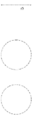
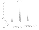
도 1은 컴퓨터-생성된 홀로그램을 갖는 3차원 물체의 재구성을 위한 방법과 관련된 디스플레이 디바이스의 개략도를 도시한다.
도 2는 종래 기술에 따라 인접한 점 확산 함수가 중첩된 점 확산 함수의 강도 분포를 도시한다.
도 3은 본 발명에 따른 컬러 필터 스트라이프 배열로서 설계된 분리기를 도시하한다.
도 4는 도 1에 도시된 공간 광 변조기 디바이스의 일부분에 의해 재구성된 7 개의 백색 물체 점의 단일 선들을 도시한다.
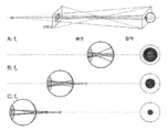
도 5는 물체 점들을 포함하는 장면을 바라 보는 관찰자에 의한 포커싱된 및 비-포커싱된 물체 점들의 망막 배치의 예를 도시한다.
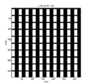
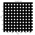
도 6은 이진 진폭 전송이 제공되는 픽셀 애퍼처 및 0.9의 필 팩터(fill factor)을 갖는 10개의 픽셀의 10배를 의미하는 공간 광 변조기 디바이스의 부분을 도시한다.
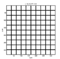
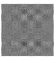
도 7은 공간 광 변조기 디바이스의 평면의 진폭 분포를 나타내는 도 6 내에 도시된 강도 분포의 푸리에 변환의 강도 분포를 도시한다.
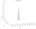
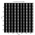
도 8은 이진 진폭 전송이 제공되는 픽셀 애퍼처의 우측 절반 및 약 0.5의 필 팩터만을 사용하는 공간 광 변조기 디바이스의 부분을 도시한다.
도 9는 공간 광 변조 디바이스의 평면의 진폭 분포를 나타내는 도 8 내에 도시된 강도 분포의 푸리에 변환의 강도 분포를 도시한다.
도 10은 이진 진폭 전송이 제공되는 픽셀 애퍼처의 좌측 절반 및 약 0.5의 필 팩터만을 사용하는 공간 광 변조기 디바이스의 부분을 도시한다.
도 11은 본 발명에 따른 디스플레이 디바이스의 조명 유닛에 사용되는 2차원 와이어 그리드 편광자 구조의 예를 도시한다.
도 12는 이진 진폭 전송이 제공되고, 수평 배향된 전기장의 투과를 위한 패턴화된 편광 필터가 사용되는, 픽셀 애퍼처 및 0.5의 필 팩터를 갖는 공간 광 변조기 디바이스의 부분을 도시한다.
도 13은 이진 진폭 전송이 제공되고, 수직 배향된 전기장의 투과를 위한 패턴화된 편광 필터가 사용되는, 픽셀 애퍼처 및 0.5의 필 팩터를 갖는 공간 광 변조기 디바이스의 부분을 도시한다.
도 14는 공간 광 변조기 디바이스의 픽셀의 2개의 서브 세트가 네스트(nest)되고, 2개의 서브 세트가 직교 출사 편광 상태를 갖는 패턴화된 리타더의 배열이 제공된 공간 광 변조기 디바이스의 부분을 도시한다.
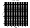
도 15는 이진 진폭 전송이 제공되는 픽셀 애퍼처 및 약 0.25의 필 팩터를 갖는 공간 광 변조기 디바이스의 부분을 도시한다.
도 16은 도 15 내에 도시된 강도 분포의 푸리에 변환의 강도 분포를 도시한다.
도 17은 공간 광 변조기 디바이스의 픽셀의 2개의 서브 세트들은 도 14의 것과 직교하여 네스트되고, 2개의 서브 세트들은 직교 출사 편광 상태를 가지는, 패턴화된 리타더들의 배열이 제공된 공간 광 변조기 디바이스의 부분을 도시한다.
도 18은 공간에서 또는 관찰자의 눈의 망막에서 재구성된 3차원 물체 점을 지칭하는, 직교 편광 상태의 바둑판 형태의 할당 패턴을 도시한다.1 shows a schematic diagram of a display device associated with a method for reconstruction of a three-dimensional object with a computer-generated hologram.
Fig. 2 shows the intensity distribution of a point spread function in which neighboring point spread functions are superimposed according to the prior art.
Figure 3 shows a separator designed as a color filter stripe arrangement according to the invention.
FIG. 4 shows single lines of seven white object points reconstructed by a portion of the spatial light modulator device shown in FIG.
Figure 5 shows an example of retinal placement of focused and non-focused object points by an observer looking at a scene containing object points.
Figure 6 shows a portion of a spatial light modulator device, which means 10
Figure 7 shows the intensity distribution of the Fourier transform of the intensity distribution shown in Figure 6, which shows the amplitude distribution of the plane of the spatial light modulator device.
Figure 8 shows a portion of a spatial light modulator device that uses only the right half of the pixel aperture and about a 0.5 fill factor to which binary amplitude transmission is provided.
Fig. 9 shows the intensity distribution of the Fourier transform of the intensity distribution shown in Fig. 8, which shows the amplitude distribution of the plane of the spatial light modulation device.
Figure 10 shows a portion of a spatial light modulator device using only the left half of the pixel aperture and about a half of the fill factor to which binary amplitude transmission is provided.
11 shows an example of a two-dimensional wire grid polarizer structure used in a lighting unit of a display device according to the present invention.
Figure 12 shows a portion of a spatial light modulator device with a pixel aperture and a fill factor of 0.5, wherein a binary amplitude transmission is provided and a patterned polarizing filter for the transmission of a horizontally oriented electric field is used.
Figure 13 shows a portion of a spatial light modulator device having a pixel aperture and a fill factor of 0.5, wherein a binary amplitude transmission is provided and a patterned polarizing filter for the transmission of a vertically oriented electric field is used.
Figure 14 shows a portion of a spatial light modulator device provided with an array of patterned retarders in which two subsets of pixels of a spatial light modulator device are nested and two subsets have an orthogonally emitted polarization state .
Figure 15 shows a portion of a spatial light modulator device having a pixel aperture provided with binary amplitude transmission and a fill factor of about 0.25.
Fig. 16 shows the intensity distribution of the Fourier transform of the intensity distribution shown in Fig.
Figure 17 is a schematic diagram of a spatial light modulator device in which two subsets of pixels of a spatial light modulator device are nested orthogonal to that of Figure 14 and two subsets have quadrature outgoing polarization states, . ≪ / RTI >
Figure 18 shows a grid-like allocation pattern of orthogonal polarization state, which refers to a three-dimensional object point reconstructed in space or in the retina of an observer's eye.
유사한 도면 부호는 개별적인 도면에서 및 제공된다면 수반되는 설명에서 유사한 컴포넌트를 나타낸다. 다음에서, 공간 광 변조기 디바이스의 앞에서와 같이, "앞에서(in front of)" 및 "뒤에서(behind)"라는 명칭은 광의 전파 방향과 관련하여 보이는 광을 의미한다.Like reference numerals designate like components in the individual drawings and, if provided, in the accompanying description. In the following, the terms "in front of" and "behind" as in the front of the spatial light modulator device refer to light seen in relation to the propagation direction of light.
2차원 및/또는 3차원 장면 또는 물체의 홀로그램 재구성을 위한 디스플레이 디바이스는 공간 광 변조기 디바이스(4) 및 조명 유닛(5)을 포함한다. 장면 또는 물체는 도 1에 도시된 바와 같이 복수의 물체 점을 포함한다. 도 1은 장면 또는 물체의 공간 광 변조기 디바이스(4)로의 인코딩을 개략적으로 나타낸다. 3차원 물체(1)는 복수의 물체 점들로 구성되고, 그 중 4개의 물체 점(1a, 1b, 1c 및 1d)만이 여기서 인코딩을 설명하기 위해 표시된다. 가상 관찰자 윈도우(2)가 또한 도시되어 있으며, 이를 통해 관찰자(여기서 눈으로 표시됨)는 재구성된 장면을 관찰할 수 있다. 정의된 시야 영역 또는 가시 영역으로서의 가상 관찰자 윈도우(2) 및 4개의 선택된 물체 점(1a, 1b, 1c 및 1d)에 의해, 피라미드 몸체가 이들 물체 점(1a, 1b, 1c 및 1d)을 통해 각각 투영되어 공간 광 변조기 디바이스(4)(여기서 부분적으로만 나타남)의 변조 표면(3)상에 연속된다. 변조 표면(3)에서, 이것은 인코딩 영역의 형상이 시야 윈도우(2)의 형상과 일치하지 않아야 하는 공간 광 변조기 디바이스(4)의 인코딩 영역을 초래한다. 즉, 공간 광 변조기 디바이스(4) 상의 인코딩 영역은 또한 시야 윈도우(2)가 물체 점을 통하여 변조 표면(3) 상으로 투영되는 것에 의해 규정된 바와 같이 더 크거나 더 작을 수 있다. 인코딩 영역은 물체의 각각의 물체 점(1a, 1b, 1c 및 1d)에 할당되며, 물체 점(1a, 1b, 1c 및 1d)은 서브-홀로그램(3a, 3b, 3c 및 3d)에 홀로그램으로 인코딩된다. 따라서, 각각의 서브-홀로그램(3a, 3b, 3c 및 3d)은 공간 광 변조기 디바이스의 변조 표면(3)의 단지 하나의 영역에만 기입되거나 인코딩된다. 도 1로부터 알 수 있는 바와 같이, 물체 점(1a, 1b, 1c, 1d)의 위치에 의존하여, 개별 서브-홀로그램(3a, 3b, 3c 및 3d)은 변조 표면(3) 상에서 완전히 또는 부분적으로만(즉, 특정 영역에서만) 오버랩될 수 있다. 이러한 방식으로 재구성될 물체(1)에 대한 홀로그램을 변조 표면(3)에 인코딩 또는 기입하기 위해서는, 물체(1)의 모든 물체 점들로 상기한 바와 같은 잘차를 수행해야 한다. 따라서, 홀로그램은 다수의 개별 서브-홀로그램(3a, 3b, 3c, 3d, ... 3n)으로 구성된다. 공간 광 변조기 디바이스에서 이러한 방식으로 컴퓨터-생성된 홀로그램은 광학 시스템과 관련하여 조명 유닛(5)(개략적으로만 도시됨)에 의한 재구성을 위해 조명된다.A display device for hologram reconstruction of a two-dimensional and / or three-dimensional scene or object comprises a spatial
도 1을 참조하면, 인코딩 영역들에 의해 정의된 홀로그램의 섹션 내의 개별 서브-홀로그램(3a, 3b, 3c 및 3d)은 본질적으로 일정한 진폭을 가지며, 그 값은 물체 점들의 밝기 및 거리, 렌즈 함수에 상응하는 위상, 렌즈의 초점 길이 및 물체 점의 깊이 좌표에 따라 변화하는 인코딩 영역의 크기의 함수로서 결정된다. 인코딩 영역에 의해 정의된 섹션 외부에서, 개별 서브-홀로그램의 진폭은 값 0을 갖는다. 홀로그램은 모든 서브-홀로그램(3a, 3b, 3c, 3d ... 3n)의 복소수 값 합에 의해 얻어진다.Referring to Figure 1, the
조명 유닛(5)은 바람직하게 홀로그램 디스플레이 디바이스 내에서 사용되는 몇몇 특정 수정을 포함할 수 있다. 조명 유닛은 코히어런트 광 및 감소된 공간 및/또는 시간 코히어런스만을 도시하는 광에 사용될 수 있다. 진폭 아포다이제이션 및 위상 아포다이제이션은 조명 유닛(5)의 입구 평면 뒤에 전파되는 강도 프로파일을 최적화하는 데 사용될 수 있다. 컬러 필터는 이를 상이한 컬러들에 대해 개별적으로 최적화할 수 있는 기회를 제공한다. 사양은 별개의 실시 예에 따라 다르다.The
이하에서는, 재구성된 장면 또는 물체 점의 이미지 품질을 감소시키는 망막 물체 점 간 크로스토크의 억제에 대해 기술하고 설명할 것이다. 이러한 망막 물체 점 간 크로스토크는 3차원 장면 또는 물체의 홀로그램 재구성 중에 초래된다.In the following, the suppression of crosstalk between retinal object points that reduces the image quality of the reconstructed scene or object point will be described and described. Such retinal object point crosstalk is caused during reconstruction of the hologram of a three-dimensional scene or object.
요구되는 화질을 얻기 위해서는 디스플레이 디바이스에 최적화해야 할 복수 개의 파라미터가 존재한다. 고려해야 할 하나의 파라미터는 인간 눈의 입사 동공의 직경이다. 이를 위해 점 확산 함수에 대한 선험적 지식이 사용되며, 이는 홀로그램 3차원 장면을 관찰하는 관찰자에게 적용되는 실제 상황에 가깝다. 디스플레이 디바이스와 관련된 정의된 위치에서 관찰자의 눈의 위치를 검출하는 눈 추적 및 눈 검출 시스템을 사용하여 얻어진 데이터가 사용될 수 있다. 관찰자의 눈의 입사 동공의 직경은 관찰자가 보고 있는 장면 또는 물체의 휘도에 의존한다. 따라서, 장면이나 물체의 현재 휘도를 참조하는 값이 사용될 수 있다. 또한, 관찰자의 위치를 기록(record)하고, 특히 관찰자의 눈의 입사 동공을 기록하기 위한 적어도 하나의 카메라를 포함하는 눈 추적 및 눈 검출 시스템에 의해 제공되는 화상(pictures)이 또한 관찰자의 눈의 입사 동공의 직경의 더 정확한 값을 추출하는데 사용될 수 있다. In order to obtain the required image quality, there are a plurality of parameters to be optimized for the display device. One parameter to consider is the diameter of the entrance pupil of the human eye. To this end, a priori knowledge of the point spread function is used, which is close to the actual situation applied to the observer observing the hologram 3D scene. Data obtained using an eye tracking and eye detection system that detects the position of the observer's eye at a defined position relative to the display device may be used. The diameter of the entrance pupil of the observer's eye depends on the scene or the brightness of the object being viewed by the observer. Therefore, a value referring to the current luminance of a scene or an object may be used. Also, images provided by the eye tracking and eye detection system, which include at least one camera for recording the position of the observer and recording the entrance pupil of the observer's eye, Can be used to extract more accurate values of the diameter of the entrance pupil.
원칙적으로 관찰자의 눈은 물체에서 나오는 3차원 필드를 "픽업(pick up)"하는 데 사용되는 에어리 모양의 점 확산 함수를 가질 수 있다. 관찰자의 눈이 예를 들어, 1m에 놓인 물체 점에 촛점을 맞추는 경우. 상기 1m에 놓이고 눈의 망막 상에 결상되는 물체 점의 점 확산 함수는 예를 들어, 0.8m에 놓인 물체 점의 점 확산 함수보다 작고, 1.5m에 배치된 물체 점의 점 확산 함수보다 작다. 다시 말해서, 관찰자가 초점을 맞추고 있는 물체 점이 가장 작은 점 확산 함수를 가진 눈의 망막으로 전달(transfer)된다. 그러나, 초점이 맞지 않거나(out-of-focus) 심지어 약간 초점이 맞지 않은 물체 점은 초점을 맞춘(in-focus) 물체 점의 점 확산 함수로서 더 큰 점 확산 함수를 가진다. 디포커싱(defocusing)은 해당 디포커스된 물체 평면의 점 확산 함수를 넓히는 것을 의미한다.In principle, the observer's eye may have an airy point spread function used to "pick up" the three-dimensional field coming from the object. The observer's eye focuses on an object point placed at 1 m, for example. The point spread function of the object point placed on the above-mentioned 1 m and formed on the retina of the eye is smaller than the point spread function of the object point placed at 0.8 m and smaller than the point spread function of the object point arranged at 1.5 m, for example. In other words, the object point on which the observer is focused is transferred to the retina of the eye with the smallest point spread function. However, object points that are out-of-focus or even slightly out of focus have a larger point spread function as a point spread function of in-focus object points. Defocusing means widening the point spread function of the defocused object plane.
물체의 모든 물체 점의 웨이브 필드의 이러한 "픽업 및 웨이브 전달(pick up and wave transfer)" 함수, 즉 초점이 맞추어진 평면의 점 확산 함수는 관찰자의 눈의 동일한 입사 동공을 통과해야 한다. 관찰자가 보고 있는 물체의 인접한 물체 점이 서로 매우 가깝다는 사실로 인해, 이들 물체 점들로부터 나오는 전달 웨이브 필드는 동일한 위치 또는 장소에서 거의 동일한 각도로 관찰자의 눈의 입사 동공과 충돌한다. 따라서, 고려되어야 하는 눈의 입사 동공의 위상 함수는 동일하다. 다시 말해서, 여기에 공통 경로 배열이 있다. 픽업되어 망막으로 전달되는 인접한 물체 점의 복소수 값 점 확산 함수는 동일하다. 그렇지 않으면 매우 멀리 떨어져 있는 물체 점에 대해 약간 상이한 점 확산 함수가 고려되어야 한다. 예를 들어, 디스플레이 디바이스의 광축에 가까운 물체 점의 전달을 위해, 약간 더 넓은 점 확산 함수로 전달되는 이미지의 에지에서의 물체 점에 대하여 더 좁은 점 확산 함수가 사용될 수 있다.This "pick up and wave transfer" function of the wave field of all object points of the object, i.e., the point spread function of the focused plane, must pass through the same incident pupil of the observer's eye. Due to the fact that adjacent object points of the object being viewed by the observer are very close to each other, the transmission wave field emerging from these object points collides with the entrance pupil of the observer's eye at approximately the same angle in the same location or place. Therefore, the phase function of the incident pupil of the eye to be considered is the same. In other words, there is a common path arrangement here. The complex-valued point spread functions of adjacent object points picked up and transmitted to the retina are the same. Otherwise, a slightly different point spread function should be considered for very distant object points. For example, for delivery of an object point near the optical axis of the display device, a narrower point spread function may be used for an object point at the edge of the image to be transmitted with a slightly wider point spread function.
물체의 인접한 물체 점들 사이의 망막 물체 점 간 크로스토크를 최소화하기 위해 다음 파라미터가 수정되어야 한다:To minimize crosstalk between retinal object points between adjacent object points of an object, the following parameters must be modified:
I) 물체 점으로부터 나오는 상대적 위상,I) Relative phase from the object point,
II) 물체 점으로부터 나오는 상대적 진폭, 및II) the relative amplitude from the object point, and
III) 2개의 인접한 회절 차수의 각도 범위 내에서 약간 시프트될 수 있는, 서로 인접한 물체 점들의 횡 방향 위치 또는 거리. 즉, ±1/60도 또는 ±1/40도의 범위에서 물체 점이 시프트될 수 있는 작은 위상 쇄기가 사용된다. 따라서, 그것은 등거리(equidistant) 도트 매트릭스와 약간 상이하다.III) The lateral position or distance of adjacent object points, which can be slightly shifted within the angular range of two adjacent diffraction orders. That is, a small phase synchronizer is used which can shift the object point in the range of ± 1/60 degrees or ± 1/40 degrees. Therefore, it is slightly different from the equidistant dot matrix.
재구성된 물체 또는 장면의 이미지 품질을 최적화하기 위해, 홀로그램 재구성을 수행하기 전에 물체 또는 장면은 개별 깊이 평면으로 분할된다. 상대적 위상, 상대적 진폭 및 측 방향 위치에 대한 이들 값은 예를 들어, 각 원색 RGB(적색, 녹색, 청색)에 대해 눈에 제시된 휘도와 상관 관계가 있는 2mm, 2.2mm, 2.4mm, .... 3.6mm로서의 입사 동공 직경들의 세트에 대해 각각의 단일 이산 깊이 평면에 대해 예를 들어, 128개의 깊이 평면들에 대해 최적화되어야 한다. 따라서, 상대적 위상, 상대적 진폭, 및 측 방향 위치에 대해 최적화된 값을 포함하는 생성된 데이터 세트는 룩업 테이블(look-up table, LUT)에 저장될 수 있다. 이러한 생성된 데이터 세트는 공간 광 변조기 디바이스에서 인코딩될 서브-홀로그램의 계산에 포함될 수 있다.To optimize the image quality of the reconstructed object or scene, the object or scene is divided into individual depth planes before performing the hologram reconstruction. These values for the relative phase, relative amplitude, and lateral position are, for example, 2 mm, 2.2 mm, 2.4 mm, and 2 mm, respectively, correlated to the luminance presented in the eye for each primary RGB (red, green, blue). For a set of incident pupil diameters as 3.6 mm, for each single discrete depth plane, for example, it should be optimized for 128 depth planes. Thus, a generated data set that includes values optimized for relative phase, relative amplitude, and lateral position may be stored in a look-up table (LUT). This generated data set may be included in the calculation of the sub-hologram to be encoded in the spatial light modulator device.
관찰자의 눈의 동공의 추정 가능한 애퍼처를 결정하기 위한 제1 접근법은 평균 휘도를 사용하여 적어도 우측 범위(right range) 내에 있을 수 있는 입사 동공 직경을 선택할 수 있으며, 우측 범위는 예를 들어 텔레비전의 경우 50-250 cd/m2, 데스크탑 모니터의 경우 100-300 cd/m2이다. 휘도 강도는 이미지 콘텐츠로부터 계산될 수 있다. 제2 접근법은 눈 추적 시스템의 데이터를 사용하여 입사 동공 직경을 측정하고 룩업 테이블의 우측 데이터 서브 세트를 선택할 수 있다.The first approach for determining the presumable aperture of the pupil of the observer's eye can be to use an average luminance to select an incident pupil diameter that can be at least in the right range and the right range, 50-250 cd / m 2 for desktop monitors and 100-300 cd / m 2 for desktop monitors. The brightness intensity can be calculated from the image content. The second approach can use the data of the eye tracking system to measure the entrance pupil diameter and select the right data subset of the lookup table.
상기 파라미터를 최적화하기 위한 하나의 가능성으로서 물체 점에 대응하는 서브-홀로그램을 계산하는 동안, 예를 들어 25 cd/m2 내지 1000 cd/m2인 요구되는 범위 내에 실질적으로 있을 수 있는 눈의 입사 동공 직경을 선택하는데 평균 휘도가 사용될 수 있다. 또 다른 가능성은 눈 추적 및 검출 시스템의 획득된 데이터를 이용하는 것일 수 있다. 이러한 데이터로 입사 동공 직경이 측정될 수 있고 룩업 테이블의 필요한 데이터 서브 세트가 선택될 수 있다. 다시 말하면, 거리 측정과 관련하여 눈 추적 및 검출 시스템의 카메라에 의해 기록된 이미지는 동공의 직경을 결정하는 데 사용될 수 있다.Sub corresponding to the object point as a possibility to optimize said parameters - during the calculation of a hologram, for example, enters the eye, which may be substantially in a 25 cd / m 2 to 1000 cd / m 2 is required range The average brightness can be used to select the pupil diameter. Another possibility is to use the acquired data of the eye tracking and detection system. With this data the incident pupil diameter can be measured and the necessary data subset of the look-up table can be selected. In other words, the image recorded by the camera of the eye tracking and detection system in connection with the distance measurement can be used to determine the pupil diameter.
또 다른 가능성은 눈의 2개의 광축의 회전 각을 정의하기 위해 관찰자의 눈의 입사 동공의 거리를 사용하는 것일 수 있다. 이 방식으로 눈의 초점 거리에 있는 2개의 광축의 교차점을 결정할 수 있다. 이를 위해 각 관찰자에 대한 개별 교정(calibration)이 필요할 수 있다. 이는 각 관찰자가 한 번 처리하는 교정 루틴을 구현하여 수행할 수 있다.Another possibility could be to use the distance of the entrance pupil of the observer's eye to define the rotation angle of the two optical axes of the eye. In this way, the intersection of two optical axes at the focal distance of the eye can be determined. To do this, individual calibrations may be required for each observer. This can be done by implementing a calibration routine that is processed once by each observer.
그러나 제한된 파라미터 세트만 수정되거나 적응되거나 변경될 수 있다. However, only a limited set of parameters can be modified, adapted or changed.
예는 실제일 수 있고 따라서 디스플레이 디바이스의 전방에 있을 수 있는 복수의 물체 점이다. 관찰자의 눈은 물체 점의 이러한 평면(들)에 집중될 수 있다. 관찰자의 눈의 점 확산 함수는 이러한 물체 점들을 픽업하여, 이들을 관찰자의 눈의 망막으로 전달한다.An example is a plurality of object points that can be real and thus be in front of the display device. The observer's eye can be focused on this plane (s) of the object point. The point spread function of the observer's eye picks up these object points and delivers them to the retina of the observer's eye.
진행할 여러 옵션이 있으며, 옵션들은 필요하거나 요구되거나 적합한 경우 결합될 수 있다.There are several options to proceed, and options can be combined if necessary, required or appropriate.
1)One)
단일 물체 점은 "관찰자의 눈의 망막에서 타겟 강도 분포(should be/target intensity distribution on the retina of the eye of the observer) I(X, Y)_retina" 및 "눈의 망막에서 총 강도 분포(is/total intensity distribution on the retina of the eye of the observer) I(X, Y)_retina"의 차이가 최소화되는 방식으로 깊이 평면에서 가상으로 시프트될 수 있고, 여기서 I는 눈의 망막의 평면에서의 강도 분포이고, x 및 y는 눈의 망막 내의 좌표이고, x 축 및 y 축의 값으로 지칭된다. 이것은 이하 SLM이라고도 지칭되는 공간 광 변조기 디바이스로 인코딩될 서브-홀로그램의 계산에 작은 오프셋 위상 함수를 도입함으로써 수행될 수 있다. 관찰자 평면에 제공된 1차원 또는 2차원 시야 윈도우의 각도 범위 내의 물체 점들의 시프트는 본 발명과 무관하다.A single object point is defined as "the intensity distribution I (X, Y) _retina" and "the total intensity distribution in the retina of the eye" (is is / target intensity distribution on the retina of the eye of the observer) I (X, Y) _retina "is minimized, where I is the intensity in the plane of the retina of the eye X and y are the coordinates within the retina of the eye and are referred to as the values of the x and y axes. This can be done by introducing a small offset phase function in the calculation of the sub-hologram to be encoded into a spatial light modulator device, also referred to hereinafter as SLM. The shift of object points within the angular range of the one- or two-dimensional view window provided in the observer plane is irrelevant to the present invention.
2)2)
상대적 위상 또는 더 정확하게는 개별 물체 점들의 상호 위상 차는 "관찰자의 눈의 망막에서 타겟 강도 분포 I(X, Y)_retina" 및 "눈의 망막에서 총 강도 분포 I(X, Y)_retina"의 차이가 최소화되는 방식으로 선택될 수 있다. 이를 위해 관찰자의 눈이 계산 과정에 포함된다. 이미지의 생성은 망막에서 계산된다. 따라서, 망막은 기준 평면이다. 시작 점은 인코딩될 장면이다. 망막에서 이미지의 반복 최적화가 수행될 수 있다. 제1 단계에서 모든 서브-홀로그램을 추가하여 망막으로 전파할 수 있다. 그런 다음, 망막 상의 총 강도 분포의 망막 상의 타겟 강도 분포로의 편차가 결정될 수 있다. 위상, 진폭 및 위치를 변경할 수 있다. 편차는 재결정될 수 있다. 이것은 반복 루프를 사용하여 수행할 수 있다. 편차 임계 값은 종료 조건으로서 예를 들어, 편차가 5%보다 작으면, 선택될 수 있다. 또한, 반복 횟수를 제한하는 것도 가능하다.Relative phase or, more precisely, the mutual phase difference of the individual object points is determined by the difference between the target intensity distribution I (X, Y) _retina at the retina of the observer's eye and the total intensity distribution I (X, Y) _retina at the retina of the eye Can be selected in such a way that the < / RTI > To do this, the observer's eye is included in the calculation process. The generation of the image is calculated in the retina. Thus, the retina is the reference plane. The starting point is the scene to be encoded. Repetitive optimization of the image in the retina can be performed. In the first step, all sub-holograms can be added and propagated to the retina. The deviation of the total intensity distribution on the retina to the target intensity distribution on the retina can then be determined. Phase, amplitude, and position. The deviation can be recrystallized. This can be done using an iterative loop. The deviation threshold can be selected as an end condition, for example, if the deviation is less than 5%. It is also possible to limit the number of repetitions.
3)3)
개개의 물체 점들의 강도 또는 진폭은 "관찰자의 눈의 망막에서 타겟 강도 분포 I(X, Y)_retina" 및 "눈의 망막에서 총 강도 분포 I(X, Y)_retina"의 차이가 최소화되는 방식으로 선택될 수 있다. 이를 위해 관찰자의 눈이 계산 과정에 포함된다. 이미지의 생성은 망막에서 계산된다. 따라서, 망막은 기준 평면이다. 시작 점은 인코딩될 장면이다. 망막에서 이미지의 반복 최적화가 수행될 수 있다. 제1 단계에서 모든 서브-홀로그램을 추가하여 망막으로 전파할 수 있다. 그런 다음, 망막 상의 총 강도 분포의 망막 상의 타겟 강도 분포로의 편차가 결정될 수 있다. 위상, 진폭 및 위치를 변경할 수 있다. 편차는 재결정될 수 있다. 이것은 반복 루프를 사용하여 수행할 수 있다. 편차 임계 값은 종료 조건으로서 예를 들어, 편차가 5%보다 작으면, 선택될 수 있다. 또한, 반복 횟수를 제한하는 것도 가능하다.The strength or amplitude of individual object points is determined by the way in which the difference between the target intensity distribution I (X, Y) _retina and the total intensity distribution I (X, Y) _retina in the retina of the eye is minimized . ≪ / RTI > To do this, the observer's eye is included in the calculation process. The generation of the image is calculated in the retina. Thus, the retina is the reference plane. The starting point is the scene to be encoded. Repetitive optimization of the image in the retina can be performed. In the first step, all sub-holograms can be added and propagated to the retina. The deviation of the total intensity distribution on the retina to the target intensity distribution on the retina can then be determined. Phase, amplitude, and position. The deviation can be recrystallized. This can be done using an iterative loop. The deviation threshold can be selected as an end condition, for example, if the deviation is less than 5%. It is also possible to limit the number of repetitions.
4)4)
예를 들어 물체 점을 픽업하여 관찰자의 눈의 망막으로 전달하는 점 확산 함수의 50%만큼 클 수 있는 적당한 큰 물체 점의 경우, "관찰자의 눈의 망막에서 타겟 강도 분포 I(X, Y)_retina" 및 "눈의 망막에서 총 강도 분포 I(X, Y)_retina"의 차이가 최소화되는 방식으로 물체 점이 수정될 수 있다. 이것은 예를 들어, 눈의 점 확산 함수에 의해 픽업되는 평면 내에 제공되는 물체 점들을 나타내는 아포다이즈된 서브-홀로그램을 사용함으로써 행해질 수 있다. 관찰자가 보고 있는 모든 물체 점이 SLM에 의해 생성된다. 따라서, SLM의 서브-홀로그램에 존재하는 복소수 값 분포는 감소된 사이드 로브를 갖는 점 확산 함수를 생성하기 위해 사용될 수 있다. 이는 관찰자의 눈의 망막에서 점 확산 함수를 생성할 수 있는 아포다이즈된 서브-홀로그램을 사용하여 수행될 수 있다. 점 확산 함수는 에어리 분포가 없어야 하지만, 예를 들어 사이드 로브가 전혀 없는 가우스 분포는 있어야 한다.For example, in the case of a suitable large object point that can be as large as 50% of the point spread function that picks up an object point and delivers it to the retina of the observer's eye, the target intensity distribution I (X, Y) _retina "And" total intensity distribution I (X, Y) _retina in the retina of the eye "is minimized. This can be done, for example, by using apodized sub-holograms that represent object points provided in the plane being picked up by the point spread function of the eye. All object points that the observer is viewing are generated by the SLM. Hence, the complex valued distribution present in the sub-hologram of the SLM can be used to create a point spread function with reduced side lobes. This can be done using an apodized sub-hologram that can generate a point spread function in the retina of the observer's eye. The point spread function should have no airy distribution, but should have a Gaussian distribution with no side lobes, for example.
물체 점에 의해 생성된 강도 분포의 사이드 로브는 "관찰자의 눈의 망막에서 타겟 강도 분포 I(X, Y)_retina" 및 "눈의 망막에서 총 강도 분포 I(X, Y)_retina"의 차이를 최소화하는 방식으로 억제되거나 심지어 형성될 수 있다. 사이드 로브는 또한 그렇게 하도록 증가될 수 있다. 사이드 로브 형상 변화는 추가 파라미터 변화로서 사용되어, 관찰자의 눈의 망막 상의 타겟 강도 분포 I(X, Y)_retina에 대한 총 강도 분포의 차이를 감소시킬 수 있다.The sidelobe of the intensity distribution generated by the object point is the difference between the target intensity distribution I (X, Y) _retina at the retina of the observer's eye and the total intensity distribution I (X, Y) _retina at the retina of the eye Minimized, or even formed. Side lobes can also be increased to do so. The side lobe shape change can be used as an additional parameter change to reduce the difference in the total intensity distribution for the target intensity distribution I (X, Y) _retina on the retina of the observer's eye.
이러한 절차는 물체 또는 장면의 적당한 큰 물체 점에 대해 보다 효율적으로 작동할 수 있다. 매우 작은 물체 점 및 따라서 큰 서브-홀로그램이 사용된다면, "관찰자의 눈의 망막에서 타겟 강도 분포 I(X, Y)_retina"와 "눈의 망막에서 총 강도 분포 I(X, Y)_retina"의 차이의 변화가 그다지 효율적이지 않을 수 있다. Such a procedure may operate more efficiently for a suitable large object point of an object or scene. If a very small object point and therefore a large sub-hologram is used, the target intensity distribution I (X, Y) _retina in the retina of the observer's eye and the total intensity distribution I (X, Y) _retina in the eye retina The change of the difference may not be very efficient.
서브-홀로그램 아포다이제이션은 a(x, y)_SLM(진폭-SLM) 및 phase(x, y) _SLM(위상-SLM)일 수 있고, 이는 c(x, y)_SLM(복소수 값 SLM)을 초래할 수 있다. 따라서, SLM 평면 내에서 사용되는 아포다이제이션은 복소수 값을 가질 수 있다.The sub-hologram apodization may be a (x, y) SLM (amplitude -SLM) and phase (x, y) SLM (phase-SLM) . Thus, the apodization used in the SLM plane may have a complex value.
5)5)
2차원(2D) 인코딩의 경우, 사용된 서브-홀로그램의 수정된 형상을 사용하여 물체 점을 형상화할 수 있다. 서브-홀로그램의 적응된 형상은 복소수-값 SLM c(x, y)_SLM과 관련되고, 이는 예를 들어 고정된 원형 또는 정방형/정사각형 형상만 사용한다. 예를 들어, 육각형 서브-홀로그램 또는 종횡비가 약간 변경된 서브-홀로그램을 사용할 수도 있다. 일반적으로 복소수 값 분포는 다양할 수 있다. 사용된 파라미터는 3차원 장면의 콘텐츠에 따라 달라질 수 있다. 이것은 서브-홀로그램의 아포다이제이션의 복소수 값 분포가 콘텐츠의 변화에 따라 변경될 수 있음을 의미한다. 다시 말해서, 개별 서브-홀로그램의 위상 및 진폭의 분포는 다양할 수 있다.In the case of two-dimensional (2D) encoding, the modified shape of the sub-hologram used can be used to shape the object point. The adapted shape of the sub-hologram is associated with a complex-valued SLM c (x, y) _SLM, which uses only a fixed circular or square / square shape, for example. For example, a hexagonal sub-hologram or a sub-hologram with a slightly changed aspect ratio may be used. In general, complex value distributions can vary. The parameters used may vary depending on the content of the three-dimensional scene. This means that the complex value distribution of the apodization of the sub-hologram can be changed according to the change of the content. In other words, the distribution of the phase and amplitude of the individual sub-holograms may vary.
6)6)
예를 들어, 모든 z-평면을 포함하는 재구성된 물체 또는 장면의 전체 최적화를 실현하는 것이 불가능하다면(여기서 z는 디스플레이 디바이스의 광축에 평행한 종방향 거리임), 수렴(시선) 추적을 사용하여 관심 있는 깊이 평면을 정의할 수 있다. 이를 위해 관찰자는 무엇을 보거나 시선을 주는지 결정된다. 눈 추적 및 검출 시스템은 관찰자의 눈길(look)이 정의될 수 있도록 눈길 또는 시선을 결정할 수 있다. 따라서, SLM으로의 서브-홀로그램의 인코딩에 대한 결과는 z-평면 또는 관찰자가 보고 있는 z-평면의 범위와 관련하여 최적화될 수 있다.For example, if it is not possible to realize a full optimization of the reconstructed object or scene including all z-planes (where z is the longitudinal distance parallel to the optical axis of the display device), then using convergence You can define the depth plane of interest. To do this, the observer decides what to look at or give an eye to. The eye tracking and detection system can determine the eye or line of sight so that the eye of the observer can be defined. Thus, the result for the encoding of the sub-hologram into the SLM can be optimized in terms of the z-plane or the range of the z-plane viewed by the observer.
1) ~ 6)에 설명된 옵션을 서로 결합하여 양호하거나 필요한 고품질을 얻을 수 있다.The options described in 1) to 6) can be combined with one another to achieve good or required high quality.
앞에서 언급한 이러한 옵션을 결합할 수 있지만 가장 직접적인 방법 또는 보다 실제적인 방법은 점 확산 함수 PSFij의 고정된 그리드를 사용하고, 3차원 물체 또는 장면의 설계된 망막 이미지에 적당히 가까운 재구성된 망막 이미지를 얻기 위해서 사이드 로브, 상대적 위상 차 및 점 확산 함수 PSFij의 강도를 최적화하는 것이다. 점 확산 함수 PSFij에 관한 접미사 ij는 2차원 그리드의 점, 바람직하게는 2차원 구형 곡선 검출기 평면 또는 망막 표면에 배치된 가상 그리드의 점을 나타내는 인덱스이다.Although the above-mentioned options can be combined, the most direct or more practical approach is to use a fixed grid of the point spread function PSF ij and obtain a reconstructed retinal image that is reasonably close to the designed retinal image of the three-dimensional object or scene Is to optimize the strength of the side lobe, the relative phase difference, and the point spread function PSF ij . The suffix ij with respect to the point spread function PSF ij is an index representing a point of a two-dimensional grid, preferably a point of a virtual grid disposed on a two-dimensional spherical curved detector plane or retina surface.
이하, 본 발명은 SLM에서 1차원(1D) 인코딩된 홀로그램에 대해 기술된다:Hereinafter, the present invention is described for a one-dimensional (1D) encoded hologram in an SLM:
일반적으로, 상술한 옵션 1) 내지 6)은 1차원 인코딩된 홀로그램에 대한 다음 옵션에 부가적으로 사용될 수 있다. 따라서, 사이드 로브 억제, 망막 물체 점 간 크로스토크 감소 및 화질에 대한 최적화가 더욱 향상될 수 있다. 다음 설명은 1차원만을 언급한다. 1차원에서만의 망막 이미지의 최적화는 단지 1차원에서 점 확산 함수 PSFij의 가장 가까운 이웃을 분석하고 최적화하는 것을 의미하며, 2차원에서 이웃하는 점 확산 함수 PSFij를 최적화하는 것보다 빠르게 실현될 수 있다. 이 때문에, 예를 들면, 반복 최적화 또는 분석 최적화가 실시간으로 수행될 수 있다. 이것은 또한 게임에서와 마찬가지로 적극적인 사용자 상호 작용을 위해 충분히 빠르고 효율적이다.In general, the options 1) to 6) described above can additionally be used to the next option for one-dimensional encoded holograms. Therefore, side lobe suppression, reduction of crosstalk between retinal object points and optimization of image quality can be further improved. The following description refers only to one dimension. Optimization of the retinal image in one dimension only means analyzing and optimizing the nearest neighbors of the point spread function PSF ij in one dimension and can be realized faster than optimizing the neighboring point spread function PSF ij in two dimensions have. For this reason, for example, iterative optimization or analysis optimization can be performed in real time. It is also fast and efficient enough for aggressive user interaction as in the game.
사람의 눈 즉, 관찰자의 눈의 제한된 각도 분해능을 사용하는 것은 SLM에서 1차원 인코딩된 홀로그램에 사용될 수 있는 하나의 옵션이다. 이를 위해, 서로에 대해 인코히어런트하고, 하나의 인코딩된 선으로 보이는, 물체 점들의 여러 1차원 인코딩된 선이 제공된다. 따라서, SLM 상의 인코히어런트 방향의 픽셀 밀도가 증가된다. 각각의 1차원 인코딩된 선은 예를 들어, 1/60도에서 관찰자에게 표시되는 물체 점의 1/3을 생성한다. 예를 들어, 관찰자가 볼 수 있는 인접한 물체 점 들간의 크로스토크를 감소시키기 위해 도(degree) 당 180 픽셀까지의 픽셀 밀도 또는 그 이하가 인코히어런트 방향 내에서 사용된다.Using the human eye, the limited angular resolution of the observer's eye, is one option that can be used in one-dimensional encoded holograms in the SLM. To this end, several one-dimensional encoded lines of object points are provided, which are in-phase with each other and appear as one encoded line. Thus, the pixel density in the incoherent direction on the SLM is increased. Each one-dimensional encoded line produces, for example, 1/3 of the object points displayed to the observer at 1/60 degrees. For example, pixel densities up to 180 pixels per degree or less are used in the incoherent direction to reduce crosstalk between adjacent object points that an observer can see.
예를 들어, 최상의 경우 조건에서 1/60 도인 인간의 눈의 각도 분해능은 분해될 수 있는 물체 점의 측 방향 확장과 동등하다. 텔레비전(TV)에 대해 일반적으로 가정될 수 있는 디스플레이 디바이스까지 3.5m의 평균 시야 거리에서, 1/60도는 2개의 물체 점들의 서로까지의 1.02mm 측 방향 확장과 동등하다. 실제 분해능이 현저히 더 적지만, 예를 들어 1.2mm의 주기적인 간격이 텔레비전 애플리케이션의 분해능 한계로서 사용될 수 있다. 실제 분해능는 이 상황에서 최상의 경우 상황에 대해 휘도가 제공되지 않음을 의미하거나, 관찰자 눈의 개별 수차가 얻어진 유효 분해능을 감소시킬 수 있음을 의미한다. 예를 가능한 한 간단히 하기 위해 이 값을 1.2mm로 선택하였다. VPO(vertical parallax only)을 의미하는 수직 홀로그램 인코딩이 사용된다면, 서브-홀로그램은 SLM 상에서 수직 스트라이프로서 배열된다.For example, the angular resolution of the human eye at 1/60 degrees in the best case condition is equivalent to the lateral expansion of the object point that can be resolved. At an average viewing distance of 3.5 m to a display device, which can generally be assumed for a television (TV), 1/60 degrees is equivalent to a 1.02 mm lateral extension of two object points to each other. Although the actual resolution is significantly less, a periodic interval of, for example, 1.2 mm can be used as the resolution limit of a television application. The actual resolution means that no brightness is provided for the best case situation in this situation, or that individual aberrations of the observer's eye can reduce the obtained effective resolution. To simplify the example as much as possible, this value was chosen to be 1.2 mm. If vertical hologram encoding, which means vertical parallax only (VPO), is used, the sub-holograms are arranged as vertical stripes on the SLM.
복소 변조 웨이브 필드를 제공하는 SLM에 대해 필수적인 프레임 속도를 줄이기 위해 컬러 필터를 사용할 수 있다. 그를 위해 SLM 픽셀에 정렬된 구조로 되어 있는 일반적으로 알려진 흡수형 염료 기반 필터 어레이가 사용될 수 있다. 현대 코팅 기술은 예를 들어 스트라이프 배열에서 노치 필터를 적용하는 것을 가능하게 한다. 이것은 컬러 스트라이프가 원색인 RGB 중 두 가지를 반사하면서 나머지 원색을 투과할 수 있음을 의미한다. 이는 1에 가까운 계수를 갖는 이러한 특정 스트라이프의 2개의 불필요한 파장을 반사하면서 0.9보다 큰 투과 계수로 행해질 수 있다.A color filter can be used to reduce the frame rate required for SLMs that provide a complex modulated wave field. For this purpose, a generally known absorbing dye-based filter array may be used which has a structure aligned with the SLM pixels. Modern coating techniques make it possible, for example, to apply a notch filter in a stripe arrangement. This means that the color stripe can transmit the remaining primary colors while reflecting two of the RGB primary colors. This can be done with a transmission factor greater than 0.9 while reflecting the two unwanted wavelengths of this particular stripe with a coefficient close to one.
예를 들어, 위에서 설명된 3.5m 시야 거리에서 인간의 눈의 최상의 경우 분해능 한계(1/60도)에 적당히 가까운 1.2mm의 수평 폭 내에서 3개의 컬러 필터 스트라이프를 제공하는 것으로 가정할 수 있다.For example, it may be assumed to provide three color filter stripes within a horizontal width of 1.2 mm, which is reasonably close to the best case resolution limit (1/60 degrees) of the human eye at the 3.5 m viewing distance described above.
종래 기술에서 1.2mm의 이러한 폭 내에서 3개의 컬러 필터 스트라이프를 사용하는 것이 알려져 있다. 따라서, 폭이 각각 400μm인 3개의 RGB 컬러 필터 스트라이프가 있다. 따라서, 적색, 녹색 및 청색 컬러 필터 스트라이프는 각각 400㎛의 폭을 갖는다.It is known in the prior art to use three color filter stripes within this width of 1.2 mm. Thus, there are three RGB color filter stripes with widths of 400 μm each. Thus, the red, green and blue color filter stripes each have a width of 400 mu m.
도 3에 따르면, 수직 스트라이프의 밀도는 훨씬 더 증가한다. 수직 스트라이프의 밀도는 종래 기술에 따른 밀도보다 예를 들어 2배, 3배(3X) 또는 4배(4X) 높다. 이제, 1.2㎜의 이러한 예시적인 폭 내에 2쌍, 3쌍 또는 4쌍 또는 RGB 컬러 필터 스트라이프가 있다. 이것은 133.3μm 또는 100μm만의 폭을 가진 컬러 스트라이프가 있음을 의미한다.According to Fig. 3, the density of vertical stripes is much more increased. The density of the vertical stripe is, for example, 2 times, 3 times (3X) or 4 times (4X) higher than the density according to the prior art. Now, there are two pairs, three pairs or four pairs or RGB color filter stripes within this exemplary width of 1.2 mm. This means that there is a color stripe having a width of only 133.3 占 퐉 or 100 占 퐉.
예를 들어, 총 40도의 누적된 회절 각을 갖는 회절 컴포넌트를 사용하는 홀로그램 디스플레이 디바이스에 대한 조건은 조명 유닛의 광원의 <0.1nm의 선폭이다. 또한, 예를 들어, 조명 유닛의 백라이트의 투명한 표면에 적용될 수 있는 반사 방지 코팅은 디스플레이 디바이스에 사용되는 브래그 회절-기반의 볼륨 격자의 광의 스쳐가는 입사(grazing incidence) 및 스펙트럼 선택성에서, 광원의 0.1nm의 중심 파장 길이의 안정성을 제공한다. 이는 예를 들어 각각 > 500mW인 광학 출력에서 447nm, 457nm, 532nm, 638nm 및 650nm에서 이용 가능한 DPSS(diode pumped solid state) 레이저를 광원으로서 사용하여 달성될 수 있다. 또한, 활성 매체 내에 또는 그 매체에 적당히 가깝게 브래그 공진기 격자를 갖는 DFB(distributed feedback) 레이저 다이오드로서, 또는 외부 브래그 공진기를 이용하는 파장 안정화된 레이저 다이오드로서의 광원도 또한 이러한 요건을 충족할 수 있다.For example, a condition for a hologram display device using a diffractive component with an accumulated diffraction angle of 40 degrees total is a line width of < 0.1 nm of the light source of the illumination unit. Also, for example, antireflective coatings that can be applied to the transparent surface of the backlight of a lighting unit, in the grazing incidence and spectral selectivity of the Bragg diffraction-based volume grating used in the display device, lt; RTI ID = 0.0 > nm. < / RTI > This can be achieved, for example, by using a diode pumped solid state (DPSS) laser available at 447 nm, 457 nm, 532 nm, 638 nm and 650 nm as the light source at optical outputs of> 500 mW each. In addition, a light source as a wavelength-stabilized laser diode, either as a distributed feedback (DFB) laser diode with a Bragg resonator grating in or near the medium of interest, or with an external Bragg resonator, may also meet this requirement.
광원, 예를 들면, 레이저 다이오드의 스위칭 시간이 어떤 이유로든 예를 들어 1ms로 감소되어야 한다면, 프로젝터로부터 알려진 추가 기계식 셔터 또는 시간 동기화된 컬러 필터 휠이 조명 유닛에서 사용될 수 있다. DFB 레이저 다이오드는 적당히 빠른 스위칭을 보여 주며, 상이한 설계 파장으로 만들어질 수 있다. 또한, 소위 Q-스위치 레이저 장치는 파장 안정화 브래그 공진기 접근법과 함께 사용될 수 있다. 이는 실질적으로 이용 가능한 레이저 광원이 본 발명에 따른 디스플레이 디바이스에 사용될 수 있음을 나타낸다.An additional mechanical shutter or time-synchronized color filter wheel known from the projector can be used in the illumination unit, if the switching time of the light source, for example a laser diode, should be reduced to, for example, 1 ms for any reason. DFB laser diodes exhibit moderately fast switching and can be made with different design wavelengths. In addition, so-called Q-switched laser devices can be used with a wavelength stabilized Bragg resonator approach. This indicates that a substantially usable laser light source can be used in the display device according to the invention.
관찰자 평면의 시야 윈도우로부터 디스플레이 디바이스까지의 3.5m 거리에서, 8mm의 수직 시야 윈도우는 SLM 상에서 195.6㎛의 픽셀 크기를 요구할 것이다. 이것은 약 200μm의 픽셀 크기를 의미한다. 따라서, 수직 픽셀 피치는 수평 픽셀 피치보다 크다.At a distance of 3.5 m from the observer plane viewing window to the display device, a 8 mm vertical viewing window would require a pixel size of 195.6 m on the SLM. This means a pixel size of about 200 mu m. Thus, the vertical pixel pitch is greater than the horizontal pixel pitch.
관찰자 평면 내의 시야 윈도우로부터 디스플레이 디바이스까지의 3.5m 대신에 단지 1.5m의 평균 시야 거리가 사용된다면, 주어진 픽셀 치수의 수는 2.3의 계수로 나누어져야 한다. 필요한 경우에 따라 이러한 경우가 있을 수 있다. 그러나, 홀로그램 1D 인코딩된 3D 텔레비전 애플리케이션의 경우, 3.5m 거리가 더 적당하다.If an average viewing distance of only 1.5m is used instead of 3.5m from the viewing window in the observer plane to the display device, the number of given pixel dimensions should be divided by a factor of 2.3. There may be cases where this is necessary. However, for hologram 1D encoded 3D television applications, a 3.5 m distance is more appropriate.
도 3은 SLM의 일부를 정면도로 도시한다. SLM은 인접한 물체 점들의 서브-홀로그램에 의해 생성된 관찰자의 눈에서 인접한 점 확산 함수들을 분리하여, 인접한 점 확산 함수들이 서로에 대해 상호 인코히어런트가 되도록 하는 분리기를 구비한다. 분리기는 여기에서 컬러 필터 배열, 바람직하게는 원색(RGB) 필터 배열로서 설계된다. 이러한 컬러 필터 배열은 주로 HD의 3배로 오버샘플링된 1D 인코딩된 홀로그램 3D 텔레비전 디스플레이 디바이스에 제공되지만, 2차원(2D) 인코딩된 홀로그램 3D 텔레비전 디스플레이 디바이스에 제공될 수도 있다. 이러한 디스플레이 디바이스는 디스플레이 디바이스까지의 평균 관찰자 시야 거리 Zmean = 3.5m를 위해 설계된다. 이 시야 거리에서, 도 3에 도시된 바와 같은 1.2 ㎜의 컬러 필터 배열의 수평 확장은 인간 눈의 각 분해능인 1/60도와 동등하다. 분리기 또는 각각의 원색 RGB(적색, 녹색, 청색)에 대한 컬러 필터 배열의 이러한 실시 예에서, 3개의 스트라이프 컬러 필터(r1, g1, b1, r2, g2, b2, r3, g3, b3)가 제공되고, SLM의 1.2mm의 수평 치수를 가진 부분에 할당된다. 다시 말해서, SLM의 수평 치수가 1.2mm인 각 부분에는 각 원색 RGB에 대해 3개의 스트라이프 컬러 필터(r1, g1, b1, r2, g2, b2, r3, g3, b3)를 포함하는 컬러 필터 배열이 제공된다. 이것은 9개의 스트라이프 컬러 필터가 1/60도의 수평 각도 범위 내에 제공된다는 것을 의미한다. 참조 부호(r1, r2 및 r3)는 적색 컬러 필터 스트라이프를 나타내고, 참조 부호(g1, g2 및 g3)는 녹색 컬러 스트라이프를 나타내고, 참조 부호(b1, b2 및 b3)는 청색 컬러 스트라이프를 나타낸다. 도 3에서, 상이한 필링(filling) 패턴은 3개의 상이한 원색 RGB의 컬러 필터 스트라이프를 표시한다.Figure 3 shows a part of the SLM in front view. The SLM has a separator that separates adjacent point spread functions in the observer's eye produced by sub-holograms of adjacent object points, such that adjacent point spread functions are mutually incoherent with respect to each other. The separator is here designed as a color filter arrangement, preferably a primary color (RGB) filter arrangement. This color filter arrangement is typically provided in a 1D encoded hologram 3D television display device that is oversampled by three times the HD, but may also be provided in a two-dimensional (2D) encoded hologram 3D television display device. Such a display device is designed for an average observer viewing distance Zmean = 3.5 m to the display device. At this viewing distance, the horizontal expansion of the 1.2 mm color filter arrangement as shown in Fig. 3 is equal to the resolution of the human eye at 1/60, which is the resolution. In this embodiment of the color filter arrangement for the separator or each primary color RGB (red, green, blue), three stripe color filters (r1, g1, b1, r2, g2, b2, r3, g3, b3) And is assigned to a portion having a horizontal dimension of 1.2 mm of the SLM. In other words, a color filter array including three stripe color filters (r1, g1, b1, r2, g2, b2, r3, g3, b3) for each primary color RGB / RTI > This means that nine stripe color filters are provided within a horizontal angle range of 1/60 degrees. Reference symbols r1, r2 and r3 denote red color filter stripes, g1, g2 and g3 denote green color stripes, and reference symbols b1, b2 and b3 denote blue color stripes. In Fig. 3, the different filling patterns represent three different primary color RGB color filter stripes.
물론, 인코딩 방향이 수평 방향인 경우, 수평 방향으로 컬러 필터 배열을 배열하는 것도 가능하다.Of course, when the encoding direction is the horizontal direction, it is also possible to arrange the color filter array in the horizontal direction.
도 3에 도시된 SLM의 일부에 의해 재구성된 물체 점들의 개략도가 도 4에 도시되어 있다. 설명을 위해 7개의 물체 점들이 사용된다.A schematic diagram of object points reconstructed by a portion of the SLM shown in FIG. 3 is shown in FIG. Seven object points are used for explanation.
도 4a는 수직 각도 거리 1/60도에서의 물체의 7개의 백색 물체 점(object point, OP)의 재구성을 도시한다. 도시된 원은 각각 관찰자의 눈의 망막 상에 존재하는 점 확산 함수의 회절 패턴의 강도 분포의 최초의 최소값을 표시한다. 단순화를 위해, 물체 점(OP)의 원형 형상이 여기에서 가정된다. 이는 이러한 측면을 설명하기 위한 것일 뿐이다. 그러나, 물체 점(OP)의 그러한 원형 형상은 용어 VPO를 사용하여 식별되는 1차원 인코딩된 홀로그램에 대해 꽤 정확하지는 않을 수 있다.Figure 4a shows the reconstruction of seven white object points (OP) of an object at a vertical angular distance of 1/60 degrees. The circles represent the initial minimum of the intensity distribution of the diffraction pattern of the point spread function present on the retina of the observer's eye, respectively. For simplicity, the circular shape of the object point OP is assumed here. This is only to illustrate this aspect. However, such a circular shape of object point OP may not be quite accurate for a one-dimensional encoded hologram identified using the term VPO.
도 4b는 수직 각도 거리 1/60도에서 7개의 적색 물체 점들의 재구성을 도시한다. 이들 7개의 적색 물체 점들은 도 4a에 따른 백색 물체 점들의 적색 서브 세트를 형성한다. 도시된 바와 같이, 적색 서브 세트는 컬러 필터 스트라이프(r1, r2 및 r3)에 의해 생성된 모든 부분을 포함한다.FIG. 4B shows the reconstruction of seven red object points at a vertical angular distance of 1/60 degrees. These seven red object points form a red subset of the white object points according to FIG. As shown, the red subset includes all portions generated by the color filter stripes rl, r2, and r3.
도 4c는 컬러 필터 스트라이프(r1)에 의해서만 생성되는 적색 서브 세트의 부분의 재구성을 도시한다. 즉, 컬러 필터 스트라이프(r1)는 도 4a에 따라 첫 번째, 네 번째, 일곱 번째, 열 번째, ...물체 점(OP)에 대한 백색 물체 점(OP)의 적색 서브 세트를 생성한다. 여기서는 컬러 필터 스트라이프(r1)가 적색 물체 점을 생성하는 것을 볼 수 있고, 여기서 적색 물체 점은 중첩되지 않는다.Figure 4c shows the reconstruction of the portion of the red subset produced only by the color filter stripe r1. That is, the color filter stripe rl produces a red subset of the white object points OP for the first, fourth, seventh, tenth, ... object points OP according to FIG. 4A. It can be seen here that the color filter stripe r1 produces a red object point, where the red object points do not overlap.
도 4d는 컬러 필터 스트라이프(r2)에 의해서만 생성되는 적색 서브 세트의 부분의 재구성을 도시한다. 다시 말해서, 컬러 필터 스트라이프(r2)는 도 4a에 따라 두 번째, 다섯 번째, 여덟 번째, 열한 번째 ... 물체 점(OP)에 대한 백색 물체 점(OP)의 적색 서브 세트를 생성한다. 또한 컬러 필터 스트라이프(r2)는 중첩되지 않는 적색 물체 점, 여기서는 2개의 물체 점을 생성한다. 컬러 필터 스트라이프(r2)에 의해 생성된 물체 점은 컬러 필터 스트라이프(r1)에 의해 생성된 물체 점까지 원의 반의 오프셋으로 재구성된다.Figure 4d shows the reconstruction of the portion of the red subset generated only by the color filter stripe r2. In other words, the color filter stripe r2 produces a red subset of the white object points OP for the second, fifth, eighth, eleventh object point OP according to FIG. 4A. In addition, the color filter stripe r2 generates a red object point that does not overlap, in this case, two object points. The object point created by the color filter stripe r2 is reconstructed with an offset of half a circle to the object point created by the color filter stripe rl.
도 4e는 컬러 필터 스트라이프(r3)에 의해서만 생성되는 적색 서브 세트의 부분의 재구성을 도시한다. 다시 말해서, 컬러 필터 스트라이프(r3)는 도 4a에 따라 세 번째, 여섯 번째, 아홉 번째, 열두 번째,... 물체 점(OP)에 대한 백색 물체 점(OP)의 적색 서브 세트를 생성한다. 또한, 컬러 필터 스트라이프(r3)는 중첩되지 않는 적색 물체 점, 여기서는 2개의 물체 점을 생성한다. 컬러 필터 스트라이프(r3)에 의해 생성된 물체 점은 컬러 필터 스트라이프(r2)에 의해 생성된 물체 점까지 원의 반의 오프셋으로 재구성된다.Figure 4e shows the reconstruction of the portion of the red subset generated only by the color filter stripe r3. In other words, the color filter stripe r3 creates a red subset of the white object points OP for the third, sixth, ninth, twelfth, ... object point OP according to FIG. 4A. In addition, the color filter stripe r3 generates a red object point that does not overlap, in this case, two object points. The object point created by the color filter stripe r3 is reconstructed with an offset of half the circle up to the object point created by the color filter stripe r2.
컬러 적색에 따른 절차는 다른 원색인 녹색과 청색에 그에 맞게 적용된다.The procedures according to the color red are applied to the other primary colors, green and blue.
결과적으로, 7개의 백색 물체 점들이 3개의 원색 RGB를 사용하여 재구성되며, 3개의 측 방향으로 변위된 컬러 필터 스트라이프는 각각의 원색 RGB에 할당된다. 1/60도의 수평 각도 범위 내에서, 도 3에서 볼 수 있는 바와 같이, r1, g1, b1, r2, g2, b2, r3, g3 및 b3으로 표시된 수직 컬러 필터 스트라이프가 제공된다. 여기서 컬러 필터 스트라이프 배열로서 설계된 분리기를 갖는 SLM을 조명하기 위해, 조정된(tailored) 수평으로 인코히어런트 광이 사용된다. 사용된 광의 공간 코히어런스는 예를 들어, 수직 방향을 따라 > 0.9이며, 이는 서브-홀로그램의 인코딩 방향이다. 1에 가깝다는 것을 의미하는 적당히 높은 코히어런스의 종방향 확장은 예를 들어, 5mm 또는 5mm ~ 10mm일 수 있다.As a result, seven white object points are reconstructed using three primary RGB colors, and three laterally displaced color filter stripes are assigned to each primary RGB color. Within the horizontal angular range of 1/60 degrees, vertical color filter stripes denoted r1, g1, b1, r2, g2, b2, r3, g3 and b3 are provided, as can be seen in Fig. Here, in order to illuminate the SLM with the separator designed as a color filter stripe arrangement, the tailored horizontally incoherent light is used. The spatial coherence of the light used is, for example, > 0.9 along the vertical direction, which is the encoding direction of the sub-hologram. A moderately high coherence longitudinal extension, which means close to 1, may be, for example, 5 mm or 5 mm to 10 mm.
서로 인접한 열이 서로에 대해 상호 인코히어런트한 방식으로 1D 인코딩에 사용되는 SLM의 상호 열의 상호 코히어런스를 준비하는 것이 중요하다. 이것은 조명 유닛에 스트라이프 모양의 광원 배열을 사용하여 수행될 수 있다.It is important to prepare the mutual coherence of the mutual columns of the SLMs used in 1D encoding in such a way that adjacent rows are mutually incoherent with respect to each other. This can be done using a stripe-shaped light source arrangement in the illumination unit.
도 4에서 알 수 있는 바와 같이, 1차원(1D) 인코딩된 홀로그램 디스플레이 디바이스의 단일 라인 또는 일부는 3개의 상이한 컬러로 그리고 단일 원색 RGB를 참조하는 추가적인 서브 세트들로 분할된다.As can be seen in FIG. 4, a single line or a portion of a one-dimensional (1D) encoded holographic display device is divided into three different colors and additional subsets referring to a single primary color RGB.
도 4로부터 더 알 수 있는 바와 같이, 코히어런트 서브 세트로부터 재구성된 물체 점들 사이에는 오버랩(overlap) 또는 중첩(superposition)이 없다. 원은 각각 재구성된 물체 점의 회절 패턴의 첫 번째 최소값을 나타내며 이는 망막 점 확산 함수의 첫 번째 최소값을 의미한다. 정확하게, 점 확산 함수의 외부 사이드 로브를 보여주는 추가 원들이 도시되거나 제공되어야 한다. 그러나, 명확성을 위해서, 첫번 째 최소값 또는 첫번 째 사이드 로브만이 도 4에 도시되어 있다.As can be further seen from FIG. 4, there is no overlap or superposition between reconstructed object points from the coherent subset. The circle represents the first minimum of the diffraction pattern of each reconstructed object point, which means the first minimum of the retinal point spread function. Exactly, additional circles showing the outer side lobe of the point spread function should be shown or provided. However, for clarity, only the first minimum or the first side lobe is shown in FIG.
일반적으로, 개별 원의 중첩이 없음은 관찰자의 눈의 망막에 인접한 점 확산 함수의 충분한 분리가 제공됨을 의미한다. 그러나 광의 작은 부분이 있을 수 있으며, 재구성된 2개의 인접한 코히어런트 물체 점들과 여전히 중첩된다. 그러나 재구성된 장면이나 물체의 품질에는 큰 영향을 미치지 않는다. 또한, 관찰자의 눈의 망막에서 얻어지는 타겟 강도 분포의 잔여 오류의 이러한 작은 값은 최적화 프로세스의 최적화 알고리즘에서 고려되어 사용될 수 있으며, 최적화 프로세스는 인식 가능한 망막 물체 점 간 크로스토크 없음을 의미하는 타겟 망막 이미지로 검출된 망막 이미지를 근사시킨다. 이 알고리즘은 타겟/실제 비교 및 파라미터의 반복 변형을 참조한다. 망막 물체 점 간 크로스토크를 회피하기 위한 망막 이미지의 추가 최적화는 예를 들어, 항목 1) ~ 6)에서 위에서 기술되고 설명된 개별적인 또는 모든 옵션을 적용함으로써 제공될 수 있다. In general, the absence of overlap of individual circles means that sufficient separation of the point spread function adjacent to the retina of the observer's eye is provided. However, there may be a small portion of light and still overlap with the two reconstructed adjacent coherent object points. However, it does not affect the quality of reconstructed scenes or objects. This small value of the residual error of the target intensity distribution obtained at the retina of the observer's eye can also be used in consideration of the optimization algorithm of the optimization process and the optimization process can be used to determine the target retinal image To approximate the detected retina image. This algorithm refers to target / actual comparisons and repeated variations of parameters. Further optimization of the retinal image to avoid retinal object point crosstalk can be provided, for example, by applying the individual or all of the options described and described above in items 1) to 6).
컬러 필터 스트라이프 배열로서 설계된 분리기를 포함하는 기술된 SLM은, 예를 들어, 수평 방향으로 0.5도 내지 1도인 평면파의 각 스펙트럼을 방출하는 적어도 하나의 광원을 갖는 조명 유닛에 의해 조명된다. 이러한 평면파의 각 스펙트럼은 코히어런트 방향이 수직 방향이고 반대 방향인 경우 관찰자 평면에서 수평 스윗 스팟에 걸치기에 충분하다. 평면파의 각 스펙트럼은 수직 방향으로 1/60도보다 상당히 작은 것, 예를 들어 단지 1/120도인 것이 바람직하며, 수직 방향은 3차원 장면 또는 물체의 재구성을 위한 1차원(1D) 인코딩된 홀로그램 디스플레이 디바이스의 서브-홀로그램의 인코딩의 방향이다.A described SLM including a separator designed as a color filter stripe array is illuminated by an illumination unit having at least one light source emitting, for example, each spectrum of a plane wave between 0.5 degrees and 1 degree in the horizontal direction. Each spectrum of this plane wave is sufficient to span the horizontal sweet spot in the observer plane if the coherent direction is vertical and the opposite direction. Preferably, each spectrum of the plane wave is significantly smaller than 1/60 degrees in the vertical direction, e.g., only 1/120 degrees, and the vertical direction is one-dimensional (1D) encoded holographic display for reconstruction of a three- It is the direction of encoding of the sub-hologram of the device.
디스플레이 디바이스에 제공된 인코딩 유닛 또는 계산 유닛은 물체 점의 고화질(HD) 콘텐츠를 도 4에 따라 서브 세트들로 분리(split)하는 것이 바람직하다. 따라서, 도 4는 또한 인코딩될 콘텐츠의 재어셈블리을 위한 명령어를 도시한다. SLM 상의 1차원(1D) 수직 라인의 ≤ 1/60도의 평면파의 각 스펙트럼 내의 4개의 컬러 필터 스트라이프 배열에 대한 각각의 제3 점 또는 심지어 각각의 제4 점이 도 3에 도시된 SLM의 일부분의 또 다른 서브-컬러 필터 라인에 할당된다. 이것은 3차원(3D) 공간에서 정의된 물체 점들에 의해 생성되는 개별 서브-홀로그램의 신속한 재할당을 제공하는 전자 회로의 블록도로 간단히 전송될 수 있다. The encoding unit or computation unit provided to the display device preferably divides the high definition (HD) content of the object point into subsets according to FIG. Thus, Figure 4 also shows the instructions for reassembly of the content to be encoded. Each third point, or even each fourth point, of the four color filter stripe arrangement in each spectrum of the plane wave of? 1 / 60th of a one-dimensional (1D) vertical line on the SLM, Is assigned to another sub-color filter line. This can simply be transferred to a block of electronic circuitry that provides rapid reallocation of individual sub-holograms generated by object points defined in three-dimensional (3D) space.
도 4에 개략적으로 도시된 실시 예는 관찰자가 물체 점들에 초점을 맞추고 있는 경우 상호 코히어런트한 물체 점들의 공간적 배치의 상황을 설명한다.The embodiment schematically illustrated in Figure 4 illustrates the situation of the spatial arrangement of mutually coherent object points when the observer is focusing on the object points.
도 5는 관찰자의 눈에서 물체 또는 장면의 초점이 포커싱된(focussed) 및 비-포커싱된(non-focussed) 물체 점들의 망막 위치를 나타낸다. 볼 수 있는 바와 같이, 비-포커싱된 물체 점의 에너지가 퍼져서 망막의 배경을 생성할 것이다. 관찰자가 3차원(3D) 장면의 전경(foreground)을 보면 가장 높은 상대적 흐림이 발생한다. 관찰자가 3차원(3D) 장면의 배경(background)을 보면 가장 낮은 상대적 흐림이 발생하며, 배경은 예를 들어, 서브-홀로그램의 컴퓨터 생성 홀로그램(computer-generated hologram, CGH)이 위치되는 평면인 홀로그램 디스플레이 평면 뒤에 예를 들어, 수 미터 멀리 떨어져 있는 홀로그램 재구성된 물체 점들을 의미한다. Figure 5 shows the retina location of focussed and non-focussed object points at the focus of an object or scene in an observer's eye. As can be seen, the energy of the non-focused object point will spread to create the background of the retina. When the observer sees the foreground of a three-dimensional (3D) scene, the highest relative fog occurs. When the observer looks at the background of a three-dimensional (3D) scene, the lowest relative fog occurs, and the background is, for example, a hologram in which the computer- generated hologram (CGH) For example, hologram reconstructed object points that are several meters away behind the display plane.
도 5의 A는 가장 완화된 상황을 도시한다. 물체 점의 초점 거리의 가장 큰 음의 값을 가진 서브-홀로그램에서 발생하는 망막의 배경이 널리 퍼진다. 그러나, 이 배경은 관찰자가 보고 있거나 집중하고 있는 물체 점에 코히어런트하게 중첩될 수 있다. 다시 말해서, 관찰자는 대략 눈과 CGH 사이의 작은 원을 보고 있다. 따라서, 원의 이미지는 정확히 눈의 망막에 이미징된다. 여기에 직사각형과 별로서 도시된 비-포커싱된 물체 점도 눈으로 이미징되지만 눈의 망막에 초점을 맞추지는 못한다. 직사각형으로서 도시된 물체 점은 CGH로서 도시낸 디스플레이 디바이스보다 훨씬 뒤에 있으므로, 도 5의 우측에서 볼 수 있는 것처럼 널리 확산된 배경만을 초래할 것이다.Figure 5A shows the most relaxed situation. The background of the retina that occurs in the sub-hologram with the largest negative value of the focal length of the object point is widespread. However, this background may coherently overlap the object point that the observer is viewing or concentrating on. In other words, the observer sees a rough circle between the approximate eye and the CGH. Thus, the original image is imaged exactly on the retina of the eye. The non-focused object points shown here as rectangles and stars are also imaged by the eye but are not focused on the retina of the eye. The object point shown as a rectangle will be far behind the display device shown as CGH, resulting in only a widely diffused background, as can be seen on the right hand side of FIG.
도 5의 B는 관찰자가 CGH의 평면에 제공되는 별을 보고있는 상황을 도시한다. 직사각형과 별로서 도시된 비-포커싱된 물체 점도 눈 안과 눈 뒤에서 이미징되지만 눈의 망막에 초점을 맞추지는 못한다.Figure 5B shows a situation in which the observer sees a star provided in the plane of the CGH. Non-focused object points, shown as rectangles and stars, are also imaged in the eye and behind the eyes, but not in the retina of the eye.
도 5의 C는 관찰자가 CGH의 평면 뒤에 제공된 직사각형을 보고 있는 상황을 도시한다. 원과 별으로서 도시된 비-포커싱된 물체 점은 눈의 망막 뒤에 이미징되므로 눈의 망막에 초점을 맞추지 못한다.Figure 5C shows a situation in which the observer sees a rectangle provided behind a plane of CGH. A non-focused object point, shown as a circle and a star, is imaged behind the retina of the eye and thus fails to focus on the retina of the eye.
컬러 필터 스트라이프 배열을 SLM 상에 분리기로서 제공함으로써, 컬러 필터 스트라이프 배열의 인접한 컬러 필터 스트라이프들 사이의 상호 코히어런스가 제거될 수 있다. 이를 위해 조명 유닛에는 공간 확장 광원을 사용할 수 있다. 콜리메이트(collimate)될 광원의 종횡비는 예를 들어 1:60일 수 있다. 이러한 방식으로, 수평 방향(인코딩 방향이 아님)에 코히어런스가 없다. 따라서, 인접한 컬러 필터 스트라이프의 코히어런트 중첩 및 이러한 방식으로 야기된 화질의 방해가 방지될 수 있다.By providing a color filter stripe arrangement as a separator on the SLM, the mutual coherence between adjacent color filter stripes of the color filter stripe arrangement can be eliminated. For this purpose, a space-extended light source can be used for the illumination unit. The aspect ratio of the light source to be collimated may be, for example, 1:60. In this way, there is no coherence in the horizontal direction (not the encoding direction). Thus, coherent superposition of adjacent color filter stripes and disturbance of image quality caused in this way can be prevented.
본 발명에 따르면, 한 세트의 컬러 필터 스트라이프(단지 하나의 적색 스트라이프, 하나의 녹색 스트라이프 및 하나의 청색 스트라이프를 포함함)에 더하여 추가적인 컬러 필터 스트라이프를 사용함으로써 도입된 추가적인 수직 분리 및 그에 따른 더 높은 픽셀 카운트는 수직 방향을 따라 이웃인 물체 점들 간의 상호 코히어런스를 제거한다. 이것은 상호 코히어런스의 추가적인 감소의 효과를 가져오고 따라서 망막 물체 점 간 크로스토크의 추가 감소를 초래한다.In accordance with the present invention, additional vertical isolation introduced by using an additional color filter stripe in addition to a set of color filter stripes (including only one red stripe, one green stripe, and one blue stripe) Pixel counts eliminate mutual coherence between neighboring object points along the vertical direction. This leads to the effect of an additional reduction of the mutual coherence and thus further reduction of crosstalk between retinal object points.
그러나, 내부 축 물체 점의 코히어런스는 여전히 존재한다. "내부 축 물체 점의 코히어런스(coherence of inner axial object points)"라는 표현은 1차원(1D) 렌즈 라인 세그먼트으로서 인코딩된 서브-홀로그램의 공통 오버랩 영역을 공유하는 물체 점의 코히어런스를 지칭한다. 이것은 단일 컬러 필터를 참조하는 물체 점들에 의해 생성된 크로스토크에도 불구하고 더 이상 다른 모든 물체 점 크로스토크를 다루지 않아야 한다는 것을 의미하며, 물체 점들이 서로의 뒤에 위치되고(디스플레이 디바이스의 광축에 평행한 z-방향을 따르는 것을 의미함), 촛점 밖(out-of-focus) 상황에서 서로 인접하여 위치된다(z-축에 수직인 평면에 있음을 의미함). 이것은 관찰자가 상이한 평면을 보고 있는 상황에서 여기에 고려된 평면에 초점이 맞지 않는다는 것을 의미한다.However, the coherence of the internal axis object point still exists. The expression "coherence of inner axial object points" refers to a coherence of an object point that shares a common overlap region of a sub-hologram encoded as a one-dimensional (1D) lens line segment do. This means that in spite of the crosstalk produced by the object points referring to the single color filter, no further object point crosstalk should be dealt with anymore, and that object points are located after each other (which is parallel to the optical axis of the display device z-direction) and are positioned adjacent to one another in an out-of-focus situation (meaning that they are in a plane perpendicular to the z-axis). This means that the planes considered here are out of focus in the situation where the observer is looking at different planes.
위에서 설명한 최적화는 정의된 물체 점의 수를 줄인 경우에만 적용해야 한다. 이는 컬러 필터 스트라이프 배열 및 홀로그램의 1차원 인코딩의 경우, 최적화는 1차원에서만 수행되며, 예를 들어 3 ~ 4개의 이웃하는 물체 점들에 대해서만 수행된다는 것을 의미한다.The above optimization should only be applied if the number of defined object points is reduced. This means that in the case of one-dimensional encoding of the color filter stripe arrangement and the hologram, the optimization is performed only in one dimension, for example only for three to four neighboring object points.
도 5는 또한 가중치 행렬(weighting matrix)을 생성하는 개념을 포함한다. 이러한 가중치 행렬은 예를 들어, 상이한 물체 점에 주어진 위상 값의 최적화에 대해 사용될 수 있다. 도 5의 A의 경우에, 디스플레이 디바이스의 뒤쪽에 있고 직사각형으로만 도시된 물체 점은 망막 상의 넓게 퍼지는 배경을 초래하고 따라서 1차(first order) 접근법에서는 무시될 수 있다.Figure 5 also includes the concept of generating a weighting matrix. This weighting matrix may be used, for example, for optimization of the phase values given to different object points. In the case of Fig. 5A, an object point behind the display device and shown only as a rectangle results in a widening background on the retina and can thus be ignored in a first order approach.
도 5의 C의 경우에, 모든 인라인(inline) 및 예를 들어, 수직으로 5mm인 공간 코히어런스의 확장을 따라 동일한 컬러 필터 스트라이프에 관련된 인라인 물체 점에 근접한 상대적 위상 값은 서로에 대해 그에 따라 최적화되어야 하는데, 3개의 축 물체 점이 서로 가깝기 때문이다. 인라인이란 여기에서 예를 들어, 1/60도 내에서 3개의 엇갈린(staggered) 선이 단 하나의 선으로 보이는 것을 의미한다. 한 가지 옵션은 단일 컬러 필터 스트라이프의 동일한 코히어런트 영역과 관련된 인라인 물체 점의 오버랩되는 서브-홀로그램을 동일한 위상 값으로 설정하는 것이다. 그러나, 일반적으로 단지 하나의 파라미터로서의 위상 값은 디스플레이된 이미지 콘텐츠에 관해서 최적화되어야 한다. 이것은 오버랩된 선명하거나 흐린 코히어런트 물체 점의 상대적인 강도를 포함한다.In the case of Fig. 5C, the relative phase values close to the inline object points associated with the same color filter stripe along all the inline and spatial coherence extensions of, for example, 5 mm vertically, It should be optimized because the three axis object points are close to each other. Inline here means, for example, that three staggered lines appear within a single line within 1/60 degrees. One option is to set the overlapping sub-holograms of inline object points associated with the same coherent region of a single color filter stripe to the same phase value. However, in general, the phase value as only one parameter has to be optimized with respect to the displayed image content. This includes the relative intensity of overlapping sharp or cloudy coherent object points.
이하의 설명은 홀로그램의 1차원 인코딩을 위해 사용될 수 있는 적어도 하나의 광원을 포함하는 조명 유닛을 참조한다. 적어도 하나의 광원에 의해 방출되는 광의 코히어런스는 가능한 한 낮아야 하지만 홀로그램 인코딩을 위해 요구되는 만큼 높아야 한다. 관찰자의 이동 및 디스플레이 디바이스에 제공되는 추가적인 회절 광학 요소들에 따라 관찰자 평면에서 시야 윈도우를 추적하기 위해 도입될 추적 각은 서브-홀로그램의 확장에 기반한 영역 내에 광로차를 도입한다. 따라서, 예를 들어, 사용되는 레이저 광원으로서 설계된 광원의 선폭은 ≤ 0.1nm 이어야 한다. 도입된 광로차뿐만 아니라, 증가된 선폭은 또한 재구성에서 번짐(smearing)을 유발할 것이다. 번짐은 디스플레이 디바이스에 사용된 회절 광학 요소에 의해 도입된 회절 분산으로 인한 것일 수 있다. 이 과정에서 모든 효과가 합산된다.The following description refers to a lighting unit comprising at least one light source that can be used for one-dimensional encoding of the hologram. The coherence of light emitted by at least one light source should be as low as possible but as high as required for hologram encoding. The tracking angle to be introduced to track the field of view in the observer plane in accordance with the movement of the observer and the additional diffractive optical elements provided in the display device introduces an optical path difference in the area based on the expansion of the sub-hologram. Thus, for example, the linewidth of the light source designed as the laser light source used should be? 0.1 nm. In addition to the introduced optical path difference, the increased linewidth will also cause smearing in the reconstruction. Blurring may be due to the diffraction dispersion introduced by the diffractive optical element used in the display device. All effects are summed up in this process.
조명 유닛의 광원의 선폭은 ≤ 0.1nm 이어야 하며, 코히어런스의 한 측면에 지나지 않는다. 또 다른 측면은 공간 코히어런스의 확장이거나 상호 코히어런스의 절대 값을 보다 분명하게 표현한 것이다. 인접한 컬러 필터 스트라이프들 사이의 상호 코히어런스는 전술한 바와 같이 제거될 수 있는 반면, 광의 충분한 코히어런스(예를 들어 > 0.8)는 컬러 필터 스트라이프의 방향을 따라, 즉 인코딩 방향을 따라 제공될 수 있다. 또한, 컬러 필터 스트라이프(들)에 평행하게 배향된 1차원 라인형 세그먼트로 맞추어진 상호 코히어런스 영역은 가장 큰 서브-홀로그램의 크기에 따라 최대 확장으로 제한된다.The linewidth of the light source of the lighting unit should be ≤ 0.1 nm and is only one side of the coherence. Another aspect is the expansion of spatial coherence or more explicit representation of the absolute value of the mutual coherence. The coherence between adjacent color filter stripes may be eliminated as described above, while a sufficient coherence of light (e.g., > 0.8) may be provided along the direction of the color filter stripe, . Further, the mutual coherence region aligned with the one-dimensional line-shaped segment oriented parallel to the color filter stripe (s) is limited to the maximum expansion according to the size of the largest sub-hologram.
광로차의 최대 값 및 따라서 사용된 광원의 선폭 또는 상호 코히어런스의 최대 범위를 지정하기 위해, 서브-홀로그램의 크기를 정의하는데 사용될 수 있는 시야 윈도우의 전체 크기 및 SLM으로의 투영이 고려되지 않아야 한다. 인간 눈의 입사 동공이나 관찰자의 눈만 고려하는 것이 더 낫다. 눈의 입사 동공은 가장 낮은 코히어런스를 특성을 갖는 요구되는 코히어런스 파라미터를 얻기 위해 광로차의 최대 값 및 따라서 사용된 광원의 선폭 또는 상호 코히어런스의 최대 범위를 특정하는데 사용될 수 있다.In order to specify the maximum value of the optical path difference and thus the line width of the light source used or the maximum range of mutual coherence, the total size of the viewing window and the projection into the SLM that can be used to define the size of the sub- do. It is better to consider only the pupil of the human eye or the eye of the observer. The incident pupil of the eye can be used to specify the maximum value of the optical path difference and hence the maximum range of the linewidth or mutual coherence of the light source used to obtain the desired coherence parameter having the lowest coherence property.
사용된 광의 코히어런스를 감소시키는 것은 교란 효과 없이 높은 이미지 콘트라스트 및 의도된 망막 이미지를 제공하기 위한 기본적인 요건이다. 즉, 의도하지 않은 코히어런트 크로스토크를 방지하기 위해 필요에 따라 적당히 높은 코히어런스를 제공하는 방식으로 광의 코히어런스를 감소시키는 것이 중요하다. 또한, 조명 유닛, 관찰자의 눈의 망막 및 SLM을 포함하는 전체 시스템, 즉 관찰자의 눈과 관련된 전체 디스플레이 디바이스의 복소수 값 점 확산 함수는 또한 최적화되어야 한다. Reducing the coherence of the light used is a fundamental requirement for providing high image contrast and intended retinal images without disturbing effects. That is, it is important to reduce the coherence of the light in such a manner as to provide an adequately high coherence if necessary in order to prevent unintentional coherent crosstalk. In addition, the complex value spread function of the entire system including the illumination unit, the observer's eye retina and the SLM, i.e. the entire display device associated with the observer's eye, must also be optimized.
이하에서, 본 발명은 SLM에서 2차원(2D) 인코딩된 홀로그램에 대해 기술되며, 이는 망막 물체 점 간 크로스토크의 감소를 위한 절차를 상세하게 사용한다:In the following, the present invention is described for a two-dimensional (2D) encoded hologram in an SLM, which details the procedure for reducing crosstalk between retinal object points:
홀로그램의 2차원(2D) 인코딩과의 관계에는 여러 측면이 있다. 관찰자의 눈의 망막에 의해 검출된 완벽한 이미지의 타겟 강도 분포 또는 최종 설계 강도 분포와 관련하여 점 확산 함수를 최적화하는 일반적인 요건은 1차원 인코딩된 홀로그램에 대해 이미 기술되고 설명되었다.There are several aspects to the relationship with the 2D (2D) encoding of holograms. The general requirement to optimize the point spread function with respect to the target intensity distribution or final design intensity distribution of the perfect image detected by the retina of the observer's eye has been previously described and described for a one-dimensionally encoded hologram.
1차원(1D) 인코딩된 홀로그램에 대해 이미 기술된 웨이브 필드를 나타내는 3차원(3D) 물체의 독립적이고 상호 코히어런트한 서브 세트의 생성은 또한 2차원(2D) 인코딩된 홀로그램에도 적용될 수 있다. 다시 말해서, 컬러 필터 배열로서 설계된 분리기는 2차원 인코딩된 홀로그램에도 적용될 수 있다. 컬러 필터 배열은 홀로그램이 2개의 코히어런트 방향으로 인코딩되는, 사용되는 SLM에 적응되어야 한다. 예를 들어, 바이엘(Bayer) 컬러 필터 어레이 또는 바이엘 패턴을 컬러 필터 배열로서 사용할 수 있다.The generation of independent and mutually coherent subsets of three-dimensional (3D) objects representing the previously described wave fields for one-dimensional (1D) encoded holograms can also be applied to two-dimensional (2D) encoded holograms. In other words, a separator designed as a color filter array can be applied to two-dimensionally encoded holograms. The color filter array should be adapted to the SLM being used, where the hologram is encoded in two coherent directions. For example, a Bayer color filter array or a Bayer pattern can be used as the color filter array.
예를 들어, 관찰자의 눈의 망막 상의 인접한 점 확산 함수들 사이의 크로스토크를 감소시키기 위해, SLM의 픽셀의 표준 픽셀 애퍼처가 사용될 수 있으며, 이는 예를 들어, 600 mm의 시야 거리에서 사용되는 2차원 인코딩된 3차원 홀로그램 디스플레이 디바이스에 대해 33 ㎛ × 33 ㎛이다. 간략화를 위해, 픽셀의 직사각형 모양의 픽셀 애퍼처가 가정될 수 있다. 또한, 예를 들어, 가우스 형 진폭 아포다이제이션 또는 소위 카이저-베셀-윈도우(Kaiser-Bessel-Window)로서 아포다이제이션 프로파일이 적용될 수 있다.For example, to reduce crosstalk between adjacent point spread functions on the retina of an observer's eye, a standard pixel aperture of a pixel of the SLM may be used, which may be a 2 < RTI ID = 0.0 > And 33 [mu] m x 33 [mu] m for a dimensionally encoded three-dimensional hologram display device. For the sake of simplicity, a pixel aperture of a rectangular shape of a pixel can be assumed. Also, apodization profiles can be applied, for example, as Gaussian amplitude apodization or so-called Kaiser-Bessel-Window.
예로서, 직사각형 모양의 픽셀 애퍼처를 갖는 SLM을 사용하는 것으로 가정한다. 이것은 도 6에 도시되어 있는데, 여기서 10 × 10 픽셀이 도시된다. SLM의 필 팩터(fill factorm FF)는 대략 FF = 0.9이며 이상적인 값이다. 이러한 필 팩터는 33 ㎛의 픽셀 피치를 갖는 투과형 SLM에 의해서가 아니라 예를 들어, LCoS(liquid crystal on silicon)로서 예를 들어, 반사 형 SLM에 의해 실현될 수 있다.As an example, it is assumed to use an SLM with a rectangular pixel aperture. This is shown in Fig. 6, where 10 x 10 pixels are shown. The fill factor FF of the SLM is approximately FF = 0.9 and is an ideal value. This fill factor can be realized by, for example, reflective SLM, for example as liquid crystal on silicon (LCoS), rather than by a transmissive SLM having a pixel pitch of 33 micrometers.
도 7은 SLM 평면의 진폭 분포를 나타내는 도 6에 도시된 강도 분포의 푸리에 변환의 강도 분포를 도시한다. 중심 스폿은 푸리에 변환 평면 내에서 SLM의 회절 패턴의 0차 회절 차수와 동등하며, 이것은 시야 윈도우의 평면 또는 관찰자 평면이다. SLM에 대해 가정된 FF = 0.9의 매우 높은 필 팩터로 인해, 중심 0차 회절 차수 스폿보다 눈에 보이는 더 높은 회절 차수는 아마 없을 것이다. 이 계산을 위해 SLM의 일정 위상이 가정된다. 다시 말해서, 인코딩에 의해 도입된 위상 변화는 관찰자의 눈의 평면 내에 존재하는 더 높은 회절 차수의 강도 값을 분명히 상당히 증가시킬 것이다. FF = 1의 필 팩터는 더 높은 회절 차수의 강도, 즉 0보다 큰 회절 차수 인덱스 m, 또는 두 방향으로 mx 및 my > 1을 갖는 회절 차수의 강도를 완전히 제거하지는 않을 것이다. 더 높은 회절 차수는 일정한 위상 분포가 SLM에 기록되지 않으면 존재할 것이다. 그러나 일반적으로 더 높은 회절 차수 피크의 값은 SLM에 디스플레이된 인코딩된 콘텐츠에 따라 변경되지만 더 높은 필 팩터는 더 작은 필 팩터보다 더 높은 회절 차수에서 더 적은 강도를 초래할 것이다. 그러나, 여기에 설명된 SLM의 일반적인 레이아웃에 대해서는 일정한 위상으로 가정된다.Fig. 7 shows the intensity distribution of the Fourier transform of the intensity distribution shown in Fig. 6 showing the amplitude distribution of the SLM plane. The center spot is equivalent to the 0th order diffraction order of the diffraction pattern of the SLM in the Fourier transform plane, which is the plane of the view window or the observer plane. Due to the very high fill factor of FF = 0.9 assumed for the SLM, there will probably be no higher diffraction orders visible than the
상기 개시된 바와 같이, 픽셀의 직사각형 형태의 애퍼처를 갖는 SLM이 가정된다. 그러나, 픽셀은 예를 들어 이제 정방형이 아니고 1 : 2의 폭 대 높이의 비율을 갖는다. 이러한 SLM은 도 8에 도시되며, 여기서 10 × 10 픽셀이 도시된다. SLM의 필 팩터(FF)는 대략 FF = 0.5이고, 즉 0.5보다 약간 작을 수 있고 예를 들어 단지 0.45일 수 있다. 그러나 상기 실시 예를 간단하고 이해하기 쉽게 유지하기 위해 여기서 0.5의 필 팩터를 가정할 수 있다. 픽셀 피치는 예를 들어 양방향, 즉 수평 및 수직으로 33 ㎛이다. SLM의 픽셀 높이는 33 μm에 가깝지만, 상기 픽셀의 폭은 16 μm에 가까울 뿐이다. SLM의 픽셀 애퍼처의 좌측 절반만이 이 실시 예에서 사용된다.As described above, an SLM with a rectangular-shaped aperture of pixels is assumed. However, the pixels are not square for example now, and have a ratio of width to height of 1: 2. This SLM is shown in Fig. 8, where 10 x 10 pixels are shown. The fill factor (FF) of the SLM may be approximately FF = 0.5, i. E., Slightly smaller than 0.5, e.g., only 0.45. However, in order to keep the embodiment simple and easy to understand, a fill factor of 0.5 can be assumed here. The pixel pitch is, for example, bi-directional, i.e., 33 [mu] m horizontally and vertically. The pixel height of the SLM is close to 33 μm, but the width of the pixel is close to 16 μm. Only the left half of the pixel aperture of the SLM is used in this embodiment.
도 9는 관찰자의 눈의 평면 내에서 도 8에 도시된 강도 분포의 푸리에 변환의 강도 분포를 도시한다. 중심 피크는 0차 회절 차수의 강도이다. y-방향, 즉 수평 방향으로의 SLM의 더 큰 필 팩터는 시야 윈도우의 평면 또는 관찰자의 평면인 관찰자의 눈의 평면에서 y-방향을 따라 감소된 사이드 로브를 초래한다. 따라서, SLM의 수평 방향을 따라 더 큰 필 팩터를 사용하는 것이 바람직하다. 도 8에 도시된 강도 분포는 빈 홀로그램을 인코딩하는 경우, 즉 SLM 평면에서 일정한 위상 값을 사용하고 SLM의 모든 픽셀에 대해 동일한 진폭을 사용하는 경우의 시야 윈도우 평면의 강도 분포와 동일하다. 도 6 및 도 7에 도시된 푸리에 변환과 비교하면, 픽셀의 감소된 수평 폭은 그 푸리에 변환 평면, 즉 관찰자의 눈이 제공되는 시야 윈도우의 평면에서 SLM의 ± 1차 수평 회절 차수를 증가시킨다. 도 8 및 도 9에 도시된 이 실시 예에서, m = ± 3보다 큰 수평 회절 차수는 이웃하는 눈에서 관찰 경험을 방해하지 않을 정도로 충분히 작은 강도를 나타낸다. 여기서, 현저한 수평 ± 4차 회절 차수는 존재하지 않는다.Fig. 9 shows the intensity distribution of the Fourier transform of the intensity distribution shown in Fig. 8 in the plane of the observer's eye. The center peak is the intensity of the 0th-order diffraction order. The larger fill factor of the SLM in the y-direction, i.e. in the horizontal direction, results in a reduced side lobe along the y-direction in the plane of the viewing window or in the plane of the observer's eye, which is the observer's plane. Therefore, it is desirable to use a larger fill factor along the horizontal direction of the SLM. The intensity distribution shown in Fig. 8 is the same as the intensity distribution of the viewing window plane when encoding empty holograms, i.e. using a constant phase value in the SLM plane and using the same amplitude for all pixels of the SLM. Compared to the Fourier transform shown in Figures 6 and 7, the reduced horizontal width of the pixel increases the ± 1st order horizontal diffraction order of the SLM in its Fourier transform plane, the plane of the viewing window in which the observer's eye is provided. In this embodiment shown in Figures 8 and 9, a horizontal diffraction order greater than m = +/- 3 represents a sufficiently small intensity to not interfere with the viewing experience in the neighboring eye. Here, there is no significant horizontal ± fourth-order diffraction order.
예를 들어, 청색 원색에 대한 파장 λ = 450 nm이고, 데스크탑 형 홀로그램 3차원(3D) 디스플레이 디바이스 내에서 사용되는 체적 격자 기반 필드 렌즈의 초점 길이 f = 600 ㎜이고 픽셀 피치가 33 μm라고 가정하면, 청색 광에 의해 형성된 관찰자 평면 내의 시야 윈도우는 약 8 mm × 8 mm의 확장을 갖는다. 3차 회절 차수는 0차 회절 차수 스폿으로부터 약 24 mm에 제공된다. 판독(read) 원색에 대해 가정된 λ = 650 nm의 파장에 대해, 3차 회절 차수는 제로 회절 차수 스폿으로부터 약 35 mm에 제공된다. 이것은 65 mm의 관찰자의 두 눈의 평균 거리의 경우, 35 mm의 거리가 충분하다는 것을 의미한다.For example, assuming that the wavelength lambda = 450 nm for the blue primary color and the focal length f = 600 mm of the volume lattice-based field lens used in the desktop type hologram three-dimensional (3D) display device and the pixel pitch is 33 μm , The viewing window in the observer plane formed by the blue light has an extension of about 8 mm x 8 mm. A third order diffraction order is provided at about 24 mm from the 0th order diffraction order spot. For the wavelength of λ = 650 nm assumed for the read primary, a third order diffraction order is provided at about 35 mm from the zero diffraction order spot. This means that for an average distance of two eyes of a 65 mm observer, a distance of 35 mm is sufficient.
도 10은 픽셀의 직사각형 형상의 애퍼처 및 대략 0.5의 필 팩터를 갖는 SLM의 이진 진폭 투과를 도시한다. 여기서 10 × 10 픽셀이 다시 도시된다. 도 10에 도시된 실시 예는 도 6에 도시된 픽셀 애퍼처의 좌측 절반만을 사용하거나 도 8에 도시된 분포에서 사용되지 않는 영역을 사용하는 것과 동일하다. 즉, 도 10에 따르면, 픽셀 애퍼처의 좌측 절반만이 사용된다. 중요한 것은 여기서 도 6에 도시된 픽셀의 초기 상황이 사용되고 이러한 초기 SLM 중 2개의 서브 세트가 생성된다는 사실이다. 우측 서브 세트는 도 8의 SLM에 의해 도시되고, 좌측 서브 세트는 도 10의 SLM에 의해 도시된다.Figure 10 shows the binary amplitude transmission of a SLM with a rectangular aperture of pixels and a fill factor of approximately 0.5. Where 10 x 10 pixels are again shown. The embodiment shown in Fig. 10 is the same as using only the left half of the pixel aperture shown in Fig. 6 or using the unused region in the distribution shown in Fig. That is, according to Fig. 10, only the left half of the pixel aperture is used. It is important to note that the initial situation of the pixel shown in FIG. 6 is used and two subsets of these initial SLMs are created. The right subset is shown by the SLM in Fig. 8, and the left subset is shown by the SLM in Fig.
도 8에 도시된, 도 6에 도시된 초기 SLM의 우측 서브 세트 및 도 10에 도시된 SLM에 의해 예시된 초기 SLM의 좌측 서브 세트는 SLM의 푸리에 평면에서 등가 강도 분포를 생성한다. 다시 말해서, 도 8에 도시된 진폭 분포의 푸리에 평면의 강도 분포와 도 10에 도시된 진폭 분포는 일정한 위상이 SLM에서 사용된다면 동일하고 도 9에 도시된 바와 같을 것이다. 이 시점에서 두 푸리에 변환의 위상이 상이하다는 것은 서로 관련성이 없다. 이것은 도 7 및 도 9의 SLM의 2개의 서브 세트가 코히어런트하게 중첩되는 경우에 고려되어야만 한다. 그러나, 본 발명에 따르면, 도 7 및 도 9에 도시된 SLM의 2개의 서브 세트의 인코히어런트 중첩이 진폭 분포로서 사용된다.The right subset of the initial SLM shown in FIG. 8 and the left subset of the initial SLM illustrated by the SLM shown in FIG. 10 produce an equivalent intensity distribution in the Fourier plane of the SLM. In other words, the intensity distribution of the Fourier plane of the amplitude distribution shown in Fig. 8 and the amplitude distribution shown in Fig. 10 are the same if a constant phase is used in the SLM and will be as shown in Fig. At this point, the phase of the two Fourier transforms is not related to each other. This must be considered when two subsets of the SLMs of Figs. 7 and 9 coherently overlap. However, according to the present invention, the incoherent superposition of the two subsets of the SLM shown in Figs. 7 and 9 is used as the amplitude distribution.
관찰자에게 디스플레이될 3차원(3D) 홀로그램 물체를 나타내는 웨이브 필드의 인코히어런트 서브 세트를 생성하기 위해 SLM의 상이한 유형의 서브 세트가 사용될 수 있다. 웨이브 필드의 인코히어런트 서브 세트를 생성하기 위해 분리기가 사용될 수 있다. 분리기로서, 공간 분리 컬러를 제공하는 컬러 필터 스트라이프 배열, 공간 분리 직교 편광 상태를 제공하는 패턴화된 리타더의 배열, 또는 SLM을 조명하는 웨이브 필드의 공간 분리된 할당을 제공하는 조명 유닛 내의 광원 배열이 사용될 수 있다.Different types of subsets of the SLM can be used to create an incoherent subset of the wave field representing a three-dimensional (3D) hologram object to be displayed to the observer. A separator may be used to generate an incoherent subset of the wave field. A splitter, comprising: a color filter stripe array providing spatial separation color; an array of patterned retarders providing spatial separation orthogonal polarization states; or a light source array in the illumination unit providing spatial separation of the wave fields illuminating the SLM Can be used.
SLM의 물리적 50 % 어드레싱이 사용된다. 단순화 및 본 발명의 간단한 설명을 위해, 본 발명의 단순한 실시 예에만 집중된다. 단순한 실시 예는 SLM의 간단한 서브 세트만을, 즉 도 6에 도시된 SLM의 2개의 간단한 서브 세트를 사용하는 것을 의미하는데, 도 8 및 도 10에 도시되어 있다. Physical 50% addressing of the SLM is used. For purposes of simplicity and a brief description of the present invention, reference should be made only to a simple embodiment of the invention. A simple embodiment means using only a simple subset of the SLM, i.e. two simple subsets of the SLM shown in FIG. 6, shown in FIGS. 8 and 10. FIG.
필 팩터(FF)가 도 10에 도시된 것보다 훨씬 더 작으면, 예를 들어, 33 ㎛ × 33 ㎛의 주요 정사각형 형상의 픽셀을 2개의 서브 세트로 세분화하는 것이 바람직하며, 이 서브 세트는 픽셀의 우측 및 좌측 부분을 사용하는 대신에 픽셀의 상부 및 하부 부분을 사용함으로써 얻어진다. 따라서, 2 : 1의 픽셀의 폭 대 높이의 비율을 구현하는 것이 바람직할 수 있다. SLM의 더 높은 회절 차수는 수평 방향이 아니라 수직 방향을 따라 지배적일 것이고, 이로 인해 관찰자의 좌측 눈과 우측 눈에 디스플레이되는 콘텐츠 간의 잠재적 크로스토크를 감소시킨다. 이 실시 예를 사용할 확률은, SLM의 구현된 레이아웃의 가장 작은 구조적 치수인 SLM의 제조 프로세스의 임계 치수가 예를 들어 단지 5 ㎛인 경우 증가된다. 3 ㎛의 임계 치수는 더 큰 필 팩터로 이어질 것이다. 따라서, 예를 들어, 단지 5 ㎛의 임계 치수를 사용하는 것이 바람직하다. If the fill factor (FF) is much smaller than that shown in Figure 10, for example, it is desirable to subdivide the pixels of the main square shape of 33 占 퐉 占 33 占 퐉 into two subsets, By using the upper and lower portions of the pixel instead of using the right and left portions of the pixel. Thus, it may be desirable to implement a ratio of width to height of a 2: 1 pixel. The higher diffraction order of the SLM will be dominant along the vertical direction, not in the horizontal direction, thereby reducing the potential cross talk between the observer's left eye and the displayed content on the right eye. The probability of using this embodiment is increased when the critical dimension of the manufacturing process of the SLM, which is the smallest structural dimension of the implemented layout of the SLM, is only 5 [mu] m, for example. A critical dimension of 3 [mu] m will lead to a larger fill factor. Thus, for example, it is preferable to use a critical dimension of only 5 [mu] m.
다음은 패턴화된 리타더의 배열로서 설계된, 분리기가 제공된 SLM의 실시 예를 기술한다. 패턴화된 리타더의 배열은 예를 들어 선형 편광 상태일 수 있는 초기 편광 상태를 갖는 SLM 상에 입사하는 광을 2개의 패턴화된 광의 서브 세트로 변환하는데 사용된다. 2개의 패턴화된 광의 서브 세트는 직교 편광 상태를 갖는다. 예를 들어, 도 6에서 볼 수 있는 바와 같이, 주요 정방형/정사각형 모양의 픽셀 애퍼처가 두 부분으로 분할된다. 이것은 초기 픽셀 카운트 및 따라서 초기 픽셀 밀도가 두 배가 된다는 것을 의미한다. 예를 들어 도 8 및 도 10에서 볼 수 있는 바와 같이, SLM의 모든 픽셀의 2개의 픽셀 서브 세트에 패턴화된 리타더의 배열이 제공된다. 픽셀의 제1 서브 세트에는 예를 들어, a + π/4 패턴화된 리타더가 제공되고 픽셀의 제2 서브 세트에는 예를 들어, a - π/4 패턴화된 리타더가 제공된다. 이러한 2개의 픽셀의 서브 세트를 포함하는 SLM이 SLM의 출사 평면에서 선형 편광된 광으로 조명되면, 상이한 패턴화된 리타더를 갖는 2개의 SLM 서브 세트를 참조하는 2개의 직교 편광된 웨이브 필드가 존재할 것이다.The following describes an embodiment of a SLM provided with a separator, designed as an array of patterned retarders. The arrangement of the patterned retarders is used to convert light incident on the SLM having an initial polarization state, which may be, for example, a linearly polarized state, into a subset of the two patterned light. A subset of the two patterned lights has an orthogonal polarization state. For example, as can be seen in FIG. 6, the main square / square shaped pixel aperture is divided into two parts. This means that the initial pixel count and thus the initial pixel density is doubled. For example, as can be seen in Figures 8 and 10, an array of patterned retarders is provided in a subset of two pixels of every pixel of the SLM. A first subset of pixels is provided with, for example, a + [pi] / 4 patterned retarders and a second subset of pixels is provided with, for example, a - [pi] / 4 patterned retarders. When an SLM comprising a subset of these two pixels is illuminated with linearly polarized light in the exit plane of the SLM, there are two orthogonally polarized wave fields that refer to two SLM subsets with different patterned retarders will be.
다음 섹션에서는 컬러 당 하나, 2개 또는 여러 개의 광원이 제공되는지 설명한다. 고전 광학 또는 일반적으로 비-편광-선택 광학이 시야 윈도우의 평면을 형성하는데 사용될 수 있다면, 관찰자에게 표시될 3차원 물체를 나타내는 웨이브 필드의 2개의 공간 인터레이스된 서브 세트를 생성하기 위하여 설명된 실시 예가 사용될 수 있다. 관찰자의 눈의 망막에 이미징된 인접한 물체 점들은 직교 편광 상태를 나타내며 따라서 상호 코히어런트 점과 동일한 방식으로 또는 더 자세히 망막 점 확산 함수와 동일한 방식으로 간섭한다. 다시 말해서, 한 방향으로는 코히어런스가 없다. 따라서, 한 방향을 따라 관찰자의 눈의 망막 상의 인접한 점 확산 함수인 인접한 물체 점들 사이의 코히어런트 망막 물체 점 간 크로스토크가 없다.The next section explains whether one, two, or multiple light sources are provided per color. If the classical optics or generally non-polarization-selective optics can be used to form the plane of the field of view, then the embodiment described for generating the two space interlaced subsets of the wave field representing the three- Can be used. Adjacent object points imaged on the retina of the observer's eye exhibit an orthogonal polarization state and thus interfere in the same manner as the mutual coherent point or more closely in the same manner as the retinal point spread function. In other words, there is no coherence in one direction. Thus, there is no coherent retinal object crosstalk between adjacent object points, which is an adjacent point spread function on the retina of the observer's eye along one direction.
그러나, 빔 경로 내의 SLM을 따르는 광학 요소가 편광 선택성이거나 단일 편광 상태만을 필요로 하는 경우, 2개의 상호 인코히어런트 웨이브 필드를 구현하기 위해 상이한 방식이 사용되어야 한다. 이 경우 공통 출사 편광 상태를 사용해야 한다. 이것은 단일 주요 광원이 사용되는 경우 상호 인코히어런스가 존재하지 않을 것이라는 것을 의미한다.However, if the optical element along the SLM in the beam path is polarization selective or requires only a single polarization state, a different approach must be used to implement the two mutually incoherent wave fields. In this case, a common outgoing polarization state must be used. This means that mutual incoherence will not be present if a single primary light source is used.
원색별로 SLM을 조명하는 적어도 2개의 상호 인코히어런트 광원을 사용해야 한다. SLM은 예를 들어, 패턴화된 리타더의 배열로서 설계된 분리기를 포함한다. 패턴화된 리타더의 배열은 SLM의 픽셀에 할당된다. 바람직하게는, 패턴화된 리타더의 배열은 픽셀의 적어도 2개의 정의된 부분, 특히 SLM의 픽셀 애퍼처의 2개의 서브 세트에 할당된 패턴화된 편광 필터의 배열로서 설계된다.At least two mutually incoherent light sources illuminating the SLM must be used for each primary color. The SLM includes, for example, a separator designed as an array of patterned retarders. An array of patterned retarders is assigned to the pixels of the SLM. Preferably, the arrangement of the patterned retarders is designed as an array of patterned polarizing filters assigned to at least two defined portions of the pixels, in particular two subsets of the pixel apertures of the SLM.
예를 들어, 2개의 직교 편광된 웨이브 필드를 수용하기 위해 최적화된 쐐기 형 조명 유닛을 사용할 수 있다. 하나의 웨이브 필드는 조명 유닛의 제1 광원으로부터 나온다. 이 광은 예를 들어 TE(transverse electric) 극성일 수 있다. 다른 웨이브 필드는 조명 유닛의 제2 광원으로부터 나온다. 이 광은 예를 들어 TM(transverse magnetic) 극성일 수 있다. 마지막으로, SLM은 2개의 웨이브 필드로 조명된다.For example, a wedge-shaped illumination unit optimized for accommodating two orthogonally polarized wave fields can be used. One wave field comes from the first light source of the illumination unit. This light may be, for example, transverse electric (TE) polarity. The other wave field comes from the second light source of the illumination unit. This light may be, for example, a transverse magnetic (TM) polarity. Finally, the SLM is illuminated with two wave fields.
도 11은 광원으로서 레이저 다이오드의 공진기의 단부에서 사용되는 2개의 미러 중 하나로서 구현될 수 있는 2차원 와이어 그리드 편광자의 실시 예를 도시한다. 도시된 패턴은 2개의 교차된 고 반사 1차원(1D) 와이어 그리드 구조를 생성함으로써 실현될 수 있다. 이 특별한 와이어 그리드 형 편광자의 주기는 π/2n보다 작으며, 여기서 π는 광원, 예를 들어 레이저 다이오드의 파장이고, n은 편광자의 기판/구조의 굴절률이다. 2개의 선형 직교 편광 상태는 1에 가까운 최대 반사율을 갖는다. 금속 2차원 스트라이프 와이어 그리드 편광자 구조는 유전체층 스택을 추가함으로써 그 반사율을 향상시킬 수 있다. 예를 들어, 도 11에서 와이어 그리드 편광자 구조 또는 상이한 미러 버전이 예를 들어, 2개의 직교 선형 출사 편광 상태를 SLM로부터 제공하기 위하여 광원 캐비티의 단부에서 사용될 수 있다. 예를 들면. 조명 유닛에 브래그 형 공진기 미러를 추가함으로써 파장 안정화가 구현될 수 있다. 따라서, 예를 들어, 0.1 nm인 광원의 선폭은 안정된 파장과 결합될 수 있으며, 이는 디스플레이 디바이스의 동작 동안 예를 들어 약 0.1nm 미만으로 시프트된다. 이 구조는 상호 인코히어런트한 SLM으로부터 2개의 직교 편광된 출사 빔을 얻기 위해 더 결합될 수 있거나, 추가로 전개될 수 있다. 이것은 비용 효율적인 단일 광원, 예를 들어, 본 발명에 따른 디스플레이 디바이스에 사용될 수 있는 레이저 다이오드 형 광원을 실현할 수 있다는 것을 의미한다. 11 shows an embodiment of a two-dimensional wire grid polarizer that can be implemented as one of the two mirrors used at the end of the resonator of the laser diode as the light source. The pattern shown can be realized by creating two crossed high reflection one-dimensional (1D) wire grid structures. The period of this particular wire grid type polarizer is less than pi / 2n, where pi is the wavelength of the light source, e.g., a laser diode, and n is the refractive index of the substrate / structure of the polarizer. The two linear orthogonal polarization states have a maximum reflectance close to unity. The metal two-dimensional stripe wire grid polarizer structure can improve its reflectivity by adding a dielectric layer stack. For example, in FIG. 11, a wire grid polarizer structure or a different mirror version may be used at the end of the light source cavity, for example, to provide two orthogonal linear exit polarization states from the SLM. For example. Wavelength stabilization can be realized by adding a Bragg type resonator mirror to the illumination unit. Thus, for example, a line width of a light source of 0.1 nm can be combined with a stable wavelength, which is shifted, for example, to less than about 0.1 nm during operation of the display device. This structure may be further combined or further developed to obtain two orthogonally polarized outgoing beams from mutually incoherent SLMs. This means that it is possible to realize a laser diode type light source which can be used in a cost-effective single light source, for example, a display device according to the present invention.
다른 애플리케이션의 경우 예를 들어. SLM 외부의 3개 이상의 상호 인코히어런트 출사 빔이 생성될 수 있다. 이 출사 빔은 선형 편광된다.For other applications, for example. Three or more mutually incoherent outgoing beams outside the SLM may be generated. This outgoing beam is linearly polarized.
도 12에는 SLM의 이진 진폭 투과가 도시되어 있다. SLM은 직사각형 모양의 픽셀 애퍼처와 약 FF = 0.5의 필 팩터를 포함한다. 여기서, 10 × 10 픽셀이 예로서 다시 표시된다. 필 팩터는 도 8에 도시된 SLM의 필 팩터와 동일하다. 패턴화된 리타더, 바람직하게는 패턴화된 편광 필터의 배열로서 설계된 분리기는 SLM의 픽셀, 특히 SLM의 픽셀의 애퍼처에 할당된다. 패턴화된 편광 필터는 수평 배향 전기장의 투과를 허용한다. 여기서는 SLM의 모든 픽셀에 할당될 수 있는 단 하나의 패턴화된 편광 필터만 필요하다.Figure 12 shows the binary amplitude transmission of the SLM. The SLM includes a rectangular pixel aperture and a fill factor of about FF = 0.5. Here, 10 x 10 pixels are displayed again as an example. The fill factor is the same as the fill factor of the SLM shown in FIG. A separator designed as an array of patterned retarders, preferably a patterned polarizing filter, is assigned to the pixels of the SLM, in particular the apertures of the pixels of the SLM. The patterned polarizing filter allows the transmission of a horizontally oriented electric field. Here, only one patterned polarizing filter that can be assigned to every pixel of the SLM is needed.
도 13은 직사각형 형상의 픽셀 애퍼처 및 대략 FF = 0.5의 필 팩터를 갖는 SLM의 이진 진폭 투과를 도시한다. 여기서 10 × 10 픽셀이 예로서 다시 도시된다. 필 팩터는 도 10에 도시된 SLM의 필 팩터와 동일하다. 패턴화된 리타더, 바람직하게는 패턴화된 편광 필터의 배열로서 설계된 분리기는 SLM의 픽셀, 특히 SLM의 픽셀의 애퍼처에 할당된다. 패턴화된 편광 필터는 수직 배향 전기장의 투과를 허용한다. 여기서는 SLM의 모든 픽셀에 할당될 수 있는 단 하나의 패턴화된 편광 필터만 필요하다.Figure 13 shows the binary amplitude transmission of a SLM with a rectangular pixel aperture and a fill factor of approximately FF = 0.5. Where 10 x 10 pixels are again shown as an example. The fill factor is the same as the fill factor of the SLM shown in FIG. A separator designed as an array of patterned retarders, preferably a patterned polarizing filter, is assigned to the pixels of the SLM, in particular the apertures of the pixels of the SLM. The patterned polarizing filter allows the transmission of a vertically oriented electric field. Here, only one patterned polarizing filter that can be assigned to every pixel of the SLM is needed.
SLM의 픽셀의 2개의 서브 세트의 네스트된 배열이 도 14에 도시되어 있다. SLM의 행(row)에서 2개의 인접한 서브 세트는 각각 SLM으로부터의 광의 직교하는 출사 편광을 생성한다. 이것은 SLM의 2개의 인접한 열이 SLM로부터의 광의 직각 출사 편광을 생성함을 의미한다. 도 14에 도시된 이 실시 예는 도 12 및 도 13에 도시된 실시 예들의 조합이다. 도 12 및 도 13에 도시된 패턴화된 필터에 따른 단 하나의 패턴화된 편광 필터만이 SLM의 실시 예에 사용될 수 없다. 따라서, 개별 픽셀 또는 SLM의 개별 열에 할당된 네스트된 편광 세그먼트를 포함하는 패턴화된 편광 필터가 사용되어야 한다. 또는, 픽셀의 2개의 인접한 서브 세트가 SLM으로부터의 광의 직교 출사 편광을 생성하는 방식으로 서로 배열되는 2개의 패턴화된 편광 필터가 사용되어야 한다.A nested arrangement of two subsets of pixels in the SLM is shown in FIG. Two adjacent subsets in the row of the SLM each produce orthogonal outgoing polarized light of light from the SLM. This means that two adjacent rows of the SLM produce a right angle outgoing polarization of light from the SLM. This embodiment shown in FIG. 14 is a combination of the embodiments shown in FIG. 12 and FIG. Only one patterned polarizing filter according to the patterned filter shown in Figures 12 and 13 can not be used in the embodiment of the SLM. Thus, a patterned polarizing filter including nested polarized segments assigned to individual pixels or individual columns of the SLM must be used. Alternatively, two patterned polarizing filters should be used in which two adjacent subsets of pixels are aligned with one another in such a manner as to produce orthogonally emitted polarized light of light from the SLM.
광의 전파 방향에서 볼 때, SLM 뒤에 추가적인 단일 편광 필터를 추가하면, 3차원 물체 장면의 일부를 운반하는 2개의 상호 인코히어런트 웨이브 필드를 포함하는 단일 광 출사 편광 상태가 제공된다. 이 웨이브 필드는 이제 디스플레이 디바이스의 모든 광학 요소를 통해 전파될 수 있고, 이는 이러한 요소들의 편광 선택도에 관계없이 빔 경로 내에서 이어진다. 예를 들어, 빔 경로에서 SLM을 따르는 편광 유형 LC 격자는 원형 편광된 광으로 조명되어야 한다; 그런 다음 그것을 조명하는 웨이브 필드의 필요한 편광 상태를 제공하기 위해 리타더가 사용되어야 한다.When viewed in the direction of propagation of light, the addition of an additional single polarization filter behind the SLM provides a single light outgoing polarization state comprising two mutually incoherent wave fields carrying a portion of the three-dimensional object scene. This wave field can now propagate through all of the optical elements of the display device, which leads in the beam path regardless of the polarization selectivity of these elements. For example, a polarization type LC grating along the SLM in the beam path must be illuminated with circularly polarized light; The retarder should then be used to provide the required polarization state of the wave field illuminating it.
또한, 홀로그램의 2차원(2D) 인코딩에서, 컬러 필터 스트라이프의 배열이 SLM 평면에서 사용될 수 있다. 이를 위해 홀로그램 3차원 데스크탑 디스플레이 디바이스의 경우 33 ㎛ × 33 ㎛일 수 있는 SLM의 픽셀의 초기 픽셀 애퍼처가 적어도 3개의 서브-픽셀 또는 3개의 서브 세트 또는 일반적으로 픽셀의 3개의 정의된 부분으로 분할되어야 한다. 도 15는 직사각형 형상의 픽셀 애퍼처 및 대략 FF = 0.25만의 필 팩터를 갖는 SLM의 이진 진폭 투과를 도시한다. 여기서 10 × 10 픽셀이 예로 다시 도시된다. 이것은 도 6에 도시된 픽셀 애퍼처의 우측 하부 1/4, 즉 최대 애퍼처의 1/4만 사용하는 것과 동일하다. 물론, 픽셀의 상이한 정의된 부분들, 예를 들어 픽셀의 좌측 상부 1/4에도 사용될 수 있다.Also, in a two-dimensional (2D) encoding of the hologram, an array of color filter stripes may be used in the SLM plane. To this end, the initial pixel aperture of a pixel of the SLM, which may be 33 microns by 33 microns for a hologram 3D desktop display device, should be divided into at least three sub-pixels or three sub-sets or generally three defined portions of a pixel do. 15 shows a binary amplitude transmission of a SLM with a rectangular pixel aperture and a fill factor of approximately FF = 0.25. Here, 10 x 10 pixels is shown again as an example. This is equivalent to using the lower right 1/4 of the pixel aperture shown in Fig. 6, i.e., only 1/4 of the maximum aperture. Of course, different defined portions of the pixel, e.g., the upper left quarter of the pixel, can also be used.
도 16은 도 15에 도시된 강도 분포의 푸리에 변환의 강도 분포를 도시한다.이 강도 분포는 관찰자의 눈의 평면에서 생성된다. 도면의 중앙 피크는 0차 회절 차수의 강도를 도시한다. SLM의 FF = 0.25의 작은 필 팩터는 더 높은 회절 차수의 강도를 증가시킨다. 예를 들면 더 높은 회절 차수를 유지하면서, 허용된 한도 내에서 관찰자 평면에서 시야 윈도우의 평면 내에 존재하는 초기 33 ㎛ × 33 ㎛ 픽셀 크기 내에 3개의 서브 픽셀을 구현하는 것이 가능하다는 것을 알 수 있다.Figure 16 shows the intensity distribution of the Fourier transform of the intensity distribution shown in Figure 15. This intensity distribution is produced in the plane of the observer's eye. The central peak in the figure shows the intensity of the 0th order diffraction order. Small fill factors of FF = 0.25 in the SLM increase the intensity of the higher diffraction order. It can be seen that it is possible to implement three subpixels within the initial 33 탆 33 탆 pixel size existing in the plane of the viewing window in the observer plane within the allowed limits while maintaining a higher diffraction order, for example.
원색 RGB 중 하나와 관련된 컬러 필터 스트라이프의 배열의 컬러 필터 세그먼트를 포함하는 서브-픽셀 또는 픽셀의 서브 세트는 예를 들어, 16 ㎛ × 16 ㎛만의 확장을 가진다. 이처럼 작은 픽셀을 구현하는 것은 아마 비용이 많이 든다. 그러나, 고도의 기술적 노력 없이도 수년 내에 가능할 수 있다. 또한, 필 팩터를 가능한 한 높게 유지하기 위해 픽셀의 제조 내에서 작은 임계 치수가 요구된다. 따라서, 예를 들어, 2차원 인코딩된 복소수 값의 SLM 내에서 컬러 필터를 구현하기 위해서는 3 ㎛의 임계 치수가 필요할 수 있다.A sub-pixel or subset of pixels comprising the color filter segment of the array of color filter stripes associated with one of the primary RGB colors has an extension of, for example, only 16 [mu] m x 16 [mu] m. Implementing such a small pixel is probably costly. However, it can be done within a few years without high technical effort. In addition, small critical dimensions are required within the fabrication of the pixel to keep the fill factor as high as possible. Thus, for example, a critical dimension of 3 占 퐉 may be required to implement a color filter within a two-dimensionally encoded complex-valued SLM.
또한, 2차원 컬러 필터 스트라이프의 배열은 유리하게는 예를 들어 직교 편광 필터로서 설계된 패턴화된 리타더의 배열과 결합될 수 있다. 그러나, 이는 SLM의 제조에서 실용적인 임계 치수를 단지 2 ㎛까지 감소시킬 수 있다. 예를 들어 33 ㎛ × 33 ㎛의 초기 픽셀 크기는 예를 들어 픽셀 또는 서브 픽셀의 6개의 정의된 부분 또는 서브 세트로 분할되어야 한다. 이는 컬러 필터 스트라이프 및 2개의 추가적인 패턴화된 편광 필터와 관련하여 세 가지 컬러를 의미한다. 각 편광 필터는 컬러 필터 스트라이프의 삼중선(triplet)에 할당된다. 따라서, 각 원색 RGB는 픽셀의 2개의 작은 서브 세트로 표현된다. 픽셀의 두 서브 세트는 직교 편광된 광을 방출한다.In addition, the arrangement of the two-dimensional color filter stripes can advantageously be combined with an arrangement of patterned retarders, for example designed as orthogonal polarization filters. However, this can reduce the practical critical dimensions in the manufacture of SLM to only 2 [mu] m. For example, the initial pixel size of 33 [mu] m x 33 [mu] m should be divided into six defined portions or subsets of pixels or subpixels, for example. This means three colors in relation to a color filter stripe and two additional patterned polarizing filters. Each polarizing filter is assigned to a triplet of color filter stripes. Thus, each primary RGB is represented by two small subsets of pixels. Two subsets of pixels emit orthogonally polarized light.
예를 들어, 도 14에 도시된 각각의 픽셀 애퍼처는 예를 들어, 픽셀의 세 가지 컬러 서브 세트로 세분될 수 있다. 그러나, 이를 위해서는 상당한 기술적 노력이 필요하며 따라서 초기 제품에 대한 가장 빠른 방법이 아닐 수도 있다.For example, each pixel aperture shown in FIG. 14 may be subdivided into three color subsets of, for example, a pixel. However, this requires considerable technical effort and may not be the fastest method for the initial product.
SLM의 픽셀들의 애퍼처들의 직사각형 배열들에 추가하여, 예를 들어, 픽셀들의 애퍼처들의 육각형 배열이 사용될 수 있다. 이들 배열에는 또한 패턴화된 리타더, 바람직하게는 패턴화된 편광 필터 및/또는 패턴화된 컬러 필터 스트라이프의 배열이 제공될 수 있다.In addition to the rectangular arrays of apertures of pixels of the SLM, for example, a hexagonal array of apertures of pixels may be used. These arrangements may also be provided with an array of patterned retarders, preferably patterned polarizing filters and / or patterned color filter stripes.
SLM에 의해 방출된 광의 2개의 직교 편광의 아마 보다 실제적인 구현은 일반적으로 쐐기 함수를 SLM의 서브-홀로그램으로 인코딩하는 것일 수 있다. 이러한 방식으로, 시야 윈도우에 걸친 각도 범위 내의 물체 점은 측 방향으로 시프트될 수 있다. 홀로그램의 2차원 인코딩을 위해, 이것은 수직 방향뿐만 아니라 수평 방향을 따라 행해질 수 있다. 다시 말해서, 도 14에서 볼 수 있는 바와 같이, 픽셀의 정방형/정사각형 영역의 좌측 분리 및 우측 분리가 수평 분리를 생성할 수 있고, 이는 인접한 직교 편광된 망막 점 확산 함수의 좌측 분리 및 우측 분리이다. 픽셀의 정사각형 영역의 상부 분리 및 하부 분리는 수직 분리를 생성할 수 있는데, 이것은 인접한 직교 편광된 망막 점 확산 함수의 상부 분리 및 하부 분리이다. 이것은 또한 SLM 평면 내의 픽셀 모양의 초기 정방형 영역이 상부 직사각형과 하부 직사각형 부분 또는 서브 세트으로 분할되는 경우에도 적용된다. 이러한 SLM은 도 14에 도시된 SLM이 시계 방향 또는 반 시계 방향으로 약 90도 회전되는 것일 것이다. 이것은도 17에 도시되어 있으며, 도 17에서는 SLM 평면에서 편광 필터들의 배열이 도시되고, 편광 필터의 배열이 도 14중 하나와 직교하도록 배열된다.Perhaps a more realistic implementation of the two orthogonal polarizations of light emitted by the SLM would typically be to encode the wedge function into a sub-hologram of the SLM. In this way, object points within the angular range over the viewing window can be shifted laterally. For two-dimensional encoding of the hologram, this can be done along the horizontal direction as well as the vertical direction. In other words, as can be seen in Fig. 14, the left and right separation of the square / square area of the pixel can produce horizontal separation, which is the left and right separation of the adjacent orthogonally polarized retina point spread function. The upper separation and the lower separation of the square area of the pixel can produce vertical separation, which is upper separation and lower separation of the adjacent orthogonally polarized retina point diffusion function. This also applies when the initial square area of the pixel shape within the SLM plane is divided into an upper rectangle and a lower rectangle portion or subset. This SLM will be that the SLM shown in Figure 14 is rotated about 90 degrees clockwise or counterclockwise. This is shown in FIG. 17, where the arrangement of polarizing filters in the SLM plane is shown in FIG. 17 and the arrangement of the polarizing filters is arranged to be orthogonal to one of FIG.
요약하면, 본 발명에 따르면, 예를 들어, 디스플레이 디바이스의 SLM에 의해 생성된 웨이브 필드의 2개 이상의 서브 세트가 존재하며, 이들은 상호 인코히어런트하다. 1차원 인코딩의 경우, 컬러 필터 스트라이프의 배열, 패턴화된 리타더의 배열, 특히 직교 편광을 갖는 편광 필터의 배열, 또는 이들의 조합이 3차원 물체 또는 장면을 부분적으로 표현하는 웨이브 필드의 상호 인코히어런트 서브 세트를 제공하기 위해 사용될 수 있다. 2차원 인코딩의 경우, 1차원 인코딩에서 2개의 직교 편광 상태를 가지며 조명 유닛 내의 상이한 광원들로부터 방출되는 광으로 SLM을 조명하는 것이 또한 가능하다. 이 광은 투과된 편광 상태의 교대하는 방향을 갖는 편광 필터의 스트라이프 패턴을 조명할 수 있다. 또한, 2차원 인코딩의 경우, 편광 필터 다음에는 추가의 비-패턴화된 리타더, 특히 단일 편광 상태만을 투과하는 편광 필터가 뒤따른다. 광이 여기 분실될 수도 있다. 그러나, 이제 디스플레이 디바이스의 빔 경로에서 SLM 다음의 광학 요소를 조명하는 2개의 상호 인코히어런트 인코딩된 웨이브 필드가 존재한다. 또한 한 방향을 따라 서브-홀로그램에서 추가 위상 쐐기로 인코딩될 수 있다. 1차원 인코딩의 경우와 대조적으로, 2차원 인코딩은 SLM의 서브-홀로그램에 인코딩된 임의의 모양의 2차원 위상 쐐기 함수의 실현을 제공한다. 잠재적인 2차원 쐐기 분포의 하나의 서브 세트만이 그를 위해 필요하다.In summary, according to the present invention, there are, for example, two or more subsets of wave fields generated by the SLM of the display device, which are mutually incoherent. In the case of one-dimensional encoding, an array of color filter stripes, an array of patterned retarders, in particular an array of polarizing filters with orthogonal polarizations, or a combination thereof, Can be used to provide a subset of the < RTI ID = 0.0 > In the case of two-dimensional encoding, it is also possible to illuminate the SLM with light that has two orthogonal polarization states in the one-dimensional encoding and is emitted from different light sources in the illumination unit. This light can illuminate the stripe pattern of the polarizing filter having alternating directions of the transmitted polarization states. Also, in the case of two-dimensional encoding, the polarizing filter is followed by an additional non-patterned retarder, in particular a polarizing filter that transmits only a single polarization state. Light may be lost here. However, there are now two mutually incoherent encoded wavelet fields illuminating the optical element after the SLM in the beam path of the display device. It can also be encoded with additional phase wedges in the sub-hologram along one direction. In contrast to the case of one-dimensional encoding, two-dimensional encoding provides the realization of a two-dimensional phase wedge function of any shape encoded in the sub-hologram of the SLM. Only one subset of the potential two-dimensional wedge distribution is needed for it.
인접한 물체 점들의 유리한 편광 인코딩 패턴은 재구성된 물체 점들에 적용되는 바둑판 같은 분포에 의해 주어진다. 또한, 허니 콤 모양의 분포가 또한 사용될 수 있으며, 이는 또한 2개의 직교 편광을 제공한다. 이것은 관찰자가 물체 점에 초점을 맞춘 경우에 물체 점의 평면 또는 관찰자의 눈의 망막 평면에 제공된다. 또한, 예를 들면, 상호 인코히어런트 패턴의 다른 무작위 분포를 사용할 수도 있다. The advantageous polarization encoding pattern of adjacent object points is given by a checkered distribution applied to the reconstructed object points. In addition, a honeycomb-shaped distribution can also be used, which also provides two orthogonal polarizations. This is provided in the plane of the object point or in the retinal plane of the observer's eye when the observer is focused on the object point. Also, for example, other random distributions of mutual incoherent patterns may be used.
도 18에는 관찰자가 이들 물체 점에 초점을 맞춘 경우에 관찰자의 눈의 망막에서 또는 공간에서 재구성된 3차원 물체 점을 나타내는 직교 편광 상태의 바둑판 모양의 할당 패턴이 도시되어 있다. 물체 점은 공간의 상이한 그리드에서 생성될 수 있다. 도 18에서, 공간에서 재구성된 98 픽셀 × 98 픽셀의 편광 상태가 보여질 수 있다. 이것은 예를 들어, 물체의 한 평면일 뿐이다. 3차원 공간에서, 인접한 깊이 평면은 교번하는 할당 패턴을 포함할 수 있다. 이것은 동일한 x-좌표(수평 방향) 및 y-좌표(수직 방향)를 갖지만 인접한 깊이 평면에 배치되는 물체 점이 바람직하게는 직교 편광 상태를 가질 수 있음을 의미한다. 다시 말해서, 도 18에 도시된 편광 상태 할당 패턴은 교대로 z-방향(깊이 방향, 즉 디스플레이 디바이스의 광축에 평행)으로 사용될 수 있으며, 즉, 편광 상태는 인접한 z-평면에 대해 반전(invert)된다.Fig. 18 shows a checkerboard pattern of orthogonal polarization states representing the reconstructed three-dimensional object points at the retina of the observer's eye or in space when the observer is focused on these object points. Object points can be generated in different grids of space. In Fig. 18, a polarization state of 98 pixels x 98 pixels reconstructed in space can be seen. This is, for example, only one plane of an object. In a three-dimensional space, adjacent depth planes may include alternating assignment patterns. This means that an object point having the same x-coordinate (horizontal direction) and y-coordinate (vertical direction) but placed in an adjacent depth plane can preferably have an orthogonal polarization state. In other words, the polarization state assignment pattern shown in Fig. 18 can be used alternately in the z-direction (in the depth direction, i.e. parallel to the optical axis of the display device), i.e. the polarization state is inverted for the adjacent z- do.
도 18의 이러한 간단한 그리드는 또한 육각형 허니콤 형 그리드로 변경될 수 있다. 장면의 콘텐츠와 관련된 초기 패턴을 임의로 변경할 수도 있다. 그러나 이것은 아마도 인코딩 프로세스의 최적화의 복잡성을 더욱 증가시킬 것이다. 또한, 편광 상태 할당 패턴은 2차원(x 및 y 방향)뿐만 아니라 z-좌표를 따라 변경될 수 있다. 그러나 가장 간단한 방법은 수직 방향(y-방향)과 수평 방향(x-방향)을 따라 고정 패턴을 사용하여 깊이 방향(z-방향)을 따라 교대로 반전시킬 수 있고 이는 관찰자와의 거리 또는 서로 상이한 z-평면 간의 거리이다.This simple grid of Fig. 18 may also be changed to a hexagonal honeycomb grid. The initial pattern associated with the content of the scene may be arbitrarily changed. However, this will probably further increase the complexity of the optimization of the encoding process. In addition, the polarization state assignment pattern can be changed along the z-coordinate as well as in two dimensions (x and y directions). However, the simplest method can alternately invert along the depth direction (z-direction) using a fixed pattern along the vertical direction (y-direction) and the horizontal direction (x-direction) z-plane.
다음 설명은 헤드 마운티드 디스플레이와 관련된 망막 물체 점 간 크로스토크 감소를 위한 점 확산 함수 PSFij의 계산을 참조한다. 그러나, 이전에 볼 수 있듯이 망막 점 확산 함수 최적화는 1차원 인코딩 및 2차원 인코딩을 위한 모든 유형의 서브-홀로그램 기반 홀로그램 디스플레이 디바이스에도 사용될 수 있다. 결과적으로, 본 발명은 직접 뷰 디스플레이 디바이스, 예를 들어, 1차원 VPO 인코딩된 홀로그램을 사용하여 텔레비전 디스플레이 디바이스의 2차원 인코딩을 사용하는 데스크탑 디스플레이 디바이스 용으로 사용될 수 있다.The following description refers to the calculation of the point spread function PSF ij for reducing the retinal object point crosstalk associated with the head-mounted display. However, as previously shown, retinal point spread function optimization can be used for all types of sub-hologram based hologram display devices for one-dimensional encoding and two-dimensional encoding. As a result, the present invention can be used for a direct view display device, for example, a desktop display device using two-dimensional encoding of a television display device using a one-dimensional VPO encoded hologram.
가장 간단한 경우는 수직 배향 서브-홀로그램을 사용하는 1차원 인코딩된 VPO(vertical parallax only) 홀로그래피이다. 조명 유닛의 광원이 코히어런스의 복잡도의 최적화된 절대 값을 제공하기 위하여 적응되면, 즉 단순한 점 광원이 아닌 경우, 가장 큰 서브-홀로그램의 크기와 같거나 그보다 작은 상호 거리를 갖는 하나의 수직 선의 픽셀만이 상호 코히어런트하도록 보장될 수 있다.The simplest case is one-dimensional encoded vertical parallax only (VPO) holography using a vertically aligned sub-hologram. If the light source of the illumination unit is adapted to provide an optimized absolute value of the complexity of the coherence, i. E., Not a simple point light source, one vertical line having a mutual distance equal to or less than the size of the largest sub- Only pixels can be guaranteed to be mutually coherent.
조명 유닛의 일차원 VPO 인코딩 및 맞춤 조명을 가정하고, 인접한 점 확산 함수의 최적화가 SLM의 한 방향을 따라 각 열에 대해 개별적으로 수행될 수 있다. 더욱이, 최적화될 이산 점 확산 함수의 가까운 이웃들만이 고려되어야 한다.Assuming a one-dimensional VPO encoding of the illumination unit and custom illumination, optimization of adjacent point spread functions may be performed separately for each column along one direction of the SLM. Moreover, only the nearest neighbors of the discrete point spread function to be optimized should be considered.
SLM의 좌측 상부 모서리의 서브-홀로그램을 예로 들면, 각 컬러를 개별적으로 제공할 수 있으며 망막 점 확산 기능 PSFij를 계산할 수 있다. 인덱스 i는 SLM의 열을 표시하는 데 사용될 수 있고 인덱스 j는 계산 프로세스에 사용된 SLM의 행을 표시하는 데 사용될 수 있다. 이것들은 공간에서 생성된 물체 점들의 망막 그리드의 인덱스이다. 이 인덱스는 또한 망막 물체 점과 관련된 이산 서브-홀로그램을 나타내는 데 사용될 수 있다. 인간 눈의 입사 동공의 정의된 직경은 장면의 밝기와 관련하여 가정될 수 있으며, 100 cd/m2의 경우 2.9 mm이다. 최적화되지 않은 모든 서브-홀로그램은 이미 생성되었거나 서로 후에 막 생성될 것이다. 예를 들어, 최적화되지 않은 모든 서브-홀로그램이 이미 생성되었다고 가정한다. 그 다음, 제1 점 확산 함수 PSF11가 계산된다.Taking the sub-hologram of the upper left corner of the SLM as an example, each color can be individually provided and the retinal point spread function PSF ij can be calculated. The index i may be used to indicate the columns of the SLM and the index j may be used to indicate the rows of the SLM used in the calculation process. These are the index of the retina grid of object points created in space. This index can also be used to represent a discrete sub-hologram associated with retinal object points. The defined diameter of the entrance pupil of the human eye can be assumed with respect to the brightness of the scene and is 2.9 mm for 100 cd / m 2 . All non-optimized sub-holograms will have already been created or will be created just after each other. For example, assume that all sub-holograms that have not been optimized have already been generated. Then, the first point spread function PSF 11 is calculated.
최적화 프로세스의 계산 부하는 고화질(HD) 콘(cone)에 집중될 수 있다. 이는 고화질 1/60도 분해능이 약 10도 각도로 중앙 콘에서만 볼 수 있다는 것을 의미한다. 최적화 동안에 주로 중심 콘에 집중할 수 있다. 따라서, 고화질(HD) 콘에서보다 많은 전력이 다른 영역들, 예를 들면, 망막의 가장자리에 대해 사용될 수 있다. 관찰자 평면에 있는 단일 관찰자에게는 눈과 색마다 하나의 고화질 콘이 제공된다. 콘의 수는 관찰자의 수에 따라 다르다. 시선 추적은 고화질 콘을 정확하게 제공하는 데 필요하다. 이것은 디스플레이 디바이스에서 시선 추적을 통합하는 것이 바람직하다는 것을 의미한다.The computational load of the optimization process can be concentrated on a high definition (HD) cone. This means that high-
더욱이, 비-고화질 콘 영역의 얇은(thinned) 물체가 사용될 수 있다. 예를 들어, 시야의 테두리에서 16배 큰 밝기로 물체 점이 재구성되는 한, 4 × 4 시닝(thinning)을 2차원 인코딩에 사용할 수 있다. 이는 영역 당 광 에너지가 일정하게 유지되기 때문에 문제가 되지 않는다. 2차원 인코딩의 경우, 수직 방향 및 수평 방향을 따라서만 매 4번째 물체 점마다 사용될 수 있다. VPO 인코딩된 홀로그램의 경우 SLM의 열을 따라 4번 시닝만을 수행할 수 있다.Moreover, a thinned object of non-high definition cone region may be used. For example, 4x4 thinning can be used for two-dimensional encoding as long as the object point is reconstructed at a brightness of 16 times greater than the border of the field of view. This is not a problem since the light energy per area is kept constant. In the case of two-dimensional encoding, it can be used for every fourth object point only along the vertical and horizontal directions. For VPO encoded holograms, only 4 times thinning along the rows of the SLM can be performed.
또한 눈과 컬러별로 하나의 고화질 콘을 낮은 분해능의 프러스텀(frustum)으로 투영하는 것이 가능하다. 이는 직접 뷰 디스플레이 디바이스와 프로젝션 디스플레이 디바이스의 조합일 수 있다. 또는, 시선 추적 데이터에 의해 정의되는 대형 저 분해능 프러스텀 생성 디스플레이 디바이스 및 고화질 콘 생성 디스플레이 디바이스의 조합일 수 있다. 그러나, 이것은 아마 상당한 기술적 노력을 추가할 수 있다.It is also possible to project one high-resolution cone to a frustum of low resolution per eye and color. This may be a combination of a direct view display device and a projection display device. Or a combination of a large low resolution frustum generation display device and a high definition cone generation display device defined by eye tracking data. However, this can probably add considerable technical effort.
관찰자의 눈의 망막에 점 확산 함수 PSF12를 생성하는 VPO 인코딩된 홀로그램 예제의 제2 서브-홀로그램으로 돌아간다. 이제 제2 서브-홀로그램만이 변경된다. 즉, 점 확산 함수 PSF11의 타겟 강도 및 설계 강도인 점 확산 함수 PSF12를 획득하기 위해, 점 확산 함수 PSF11에 대한 위상 오프셋 및 점 확산 함수 PSF12의 강도 값이 변경된다. 즉, 예를 들어 그것은 위상 오프셋 및 강도 변경에 사용된다. 그 다음, 코히어런트하게 더해진 2개의 점 확산 함수 PSF11 및 PSF12에 인접하여, 점 확산 함수 PSF13가 배치된다. 이제, 점 확산 함수 PSF11 + PSF12 + PSF13의 코히어런트 합의 설계 강도 분포를 얻기 위해 초기 점 확산 함수 PSF13를 변경하기 위한 위상 오프셋 및 강도 변화가 한번 더 사용된다. 그런데, 이것은 j에서 j + 1에서 j + 2 ... j + N까지, 즉 SLM의 이산 열, 여기서는 열 1에 의해 형성된 마지막 점 확산 함수 PSFij에 의해 설명될 수 있다. 그런 다음 SLM의 다음 열이 수행된다. VPO 인코딩된 홀로그램의 경우 SLM의 열을 따라 행해진 최적화 프로세스가 병렬로 수행될 수 있다. 이것은 맞춤 조명을 사용하는 경우 SLM의 열이 상호 인코히어런트하다는 사실에 기인한다. 계산 및 최적화 알고리즘을 빠르고 간단하게 유지하기 위해, 망막에 국부적으로 제공된 점 확산 함수의 피크 강도 값을 최적화 프로세스의 기준으로 사용할 수 있다. 예를 들어. 단일 피크 강도 값 대신 1/60도 각도 범위의 적분(integral) 강도 값을 사용하는 것이 여전히 의미 있을 수 있다. 그러나 그 차이는 작다. 예를 들어, 최적화를 위한 단일 점 확산 함수의 3개 이상의 샘플링 점을 사용하는 것은 더 많은 노력, 즉 더 많은 계산 부하를 추가할 수 있다.Returning to the second sub-hologram of the VPO-encoded hologram example generating the point spread function PSF 12 in the retina of the observer's eye. Only the second sub-hologram is changed. In other words, to obtain a point spread function, the target strength and design strength of a point spread function PSF 12 of the PSF 11, the intensity value of the phase offset and the point spread function PSF 12 for a point spread function PSF 11 is changed. That is, for example, it is used for phase offset and intensity changes. Next, adjacent to the two point spread functions PSF 11 and PSF 12 coherently added, a point spread function PSF 13 is arranged. Now, one more phase offset and intensity change is used to change the initial point spread function PSF 13 to obtain a coherent sum design intensity distribution of the point spread function PSF 11 + PSF 12 + PSF 13 . However, this can be explained by the last point spread function PSF ij formed by j + 1 to j + 2 ... j + N in j, that is, the discrete column of SLM, here
홀로그램의 2차원 인코딩을 위해, 최적화는 홀로그램의 1차원 인코딩에 대해 아날로그 방식으로 수행될 수 있다. 예를 들어, 그것은 서브-홀로그램의 상부 좌측 모서리 또는 물체 점들의 망막 점 확산 함수 PSFij에서 시작될 수 있다. 제1 점 확산 함수 PSF11가 형성되고 제2 점 확산 함수 PSF12가 더해진다. 이러한 합해진 점 확산 함수는 필요하다면 위상 오프셋과 강도의 변화를 사용하여 최적화된다. 그러면, 예를 들어, 점 확산 함수 PSF21이 더해지고 위상 및 강도를 사용하여 또한 최적화된다. 이제 점 확산 함수 PSF22가 더해지고 필요에 따라 위상 오프셋과 강도 값이 변경된다. 그러면, 예를 들어 점 확산 함수 PSF13이 더해지고 위상 오프셋 및 강도 값이 최적화된다. 점 확산 함수 PSFij의 다음 인덱스들은 예를 들어, 23 및 31이 될 수 있고, 그 뒤에 14가 될 수 있다. 예를 들어, 이는 서브-홀로그램의 좌측 상단 모서리에서 시작하여 우측 하단 모서리에 도달할 때까지 단계별로 장면을 채우고 최적화할 수 있음을 의미한다.For two-dimensional encoding of the hologram, the optimization may be performed in an analog manner for one-dimensional encoding of the hologram. For example, it may start at the upper left corner of the sub-hologram or the retinal point spread function PSF ij of object points. A first point spread function PSF 11 is formed and a second point spread function PSF 12 is added. This combined point spread function is optimized using a change in phase offset and intensity if necessary. Then, for example, the point spread function PSF 21 is added and is also optimized using phase and intensity. The point spread function PSF 22 is now added and the phase offset and intensity values are changed as needed. Then, for example, the point spread function PSF 13 is added and the phase offset and intensity values are optimized. The following indices of the point spread function PSF ij may be, for example, 23 and 31, followed by 14. For example, this means that you can start with the upper left corner of the sub-hologram and fill and optimize the scene step by step until you reach the bottom right corner.
이 최적화 프로세스에 대한 상이한 경로가 사용될 수 있다. 예를 들어 점 확산 함수 PSF11로 시작한 다음 점 확산 함수 PSF12, PSF13, PSF14, ..내지 PSF1N으로 갈 수 있고, 여기서 N은 생성될 수직 물체 점들의 수, 예를 들어 1000개의 물체 점 또는 심지어 2000개의 물체 점이다. M에서 수평적으로 생성되는 물체 점들의 수는 예를 들면 2000 내지 4000일 수 있다. 상세하게, 이것은 처음에 서브-홀로그램의 첫 번째 열이 채워지고 완료된 다음 단계별로 두 번째 열의 요소들, 즉 점 확산 함수 PSF21, PSF22, PSF23, PSF24 , ..내지 PSF2N가 더해짐을 의미할 수 있다. 여기에서는 단계별 채우기 및 최적화가 서브-홀로그램의 좌측에서 우측으로 수행된다. 이 방식으로 M, N의 2차원 행렬을 생성할 수 있다.Different paths for this optimization process may be used. For example, we can go to the next point spread function PSF 12 , PSF 13 , PSF 14 , ... to PSF 1N starting with the point spread function PSF 11 , where N is the number of vertical object points to be created, Point or even 2000 object points. The number of object points horizontally generated in M may be, for example, 2000 to 4000. In detail, this means that the first column of the sub-hologram is first filled, and then the elements of the second column, i.e., the point spread functions PSF 21 , PSF 22 , PSF 23 , PSF 24 , ... to PSF 2N , It can mean. Here step-by-step fills and optimizations are performed from left to right of the sub-hologram. In this way, a two-dimensional matrix of M and N can be generated.
SLM에 대한 미리 정의 가능한 방향을 따라 계속되는 이러한 최적화는 또한 멀티 코어 집적 회로가 사용되는 경우 병렬 방식으로 수행될 수 있다. 따라서, 서브-홀로그램 내의 시작점은 임의 방식으로 선택될 수 있거나 적어도 몇몇 시작점이 선택될 수 있다. 서브-홀로그램의 국부적으로 최적화된 영역(최적화 중에 채워지는 영역)이 서로 충돌하면, 천이 영역을 최적화할 수 있다. 상호 갭이 예를 들어. 5개의 점 확산 함수 PSFij만이라면. 이것은 이미 행해질 수 있다. 이것은 점 확산 함수가 하나의 구역의 테두리(rim)에 추가될 수 있고 이웃하는 구역의 테두리의 작은 부분이 2개의 인접한 구역 사이에 존재하는 갭의 채우기 중에 이미 고려될 수 있음을 의미한다.This optimization, which follows the predefinable direction for the SLM, can also be performed in a parallel manner when a multicore integrated circuit is used. Thus, the starting point in the sub-hologram can be selected in any way, or at least some starting points can be selected. If the locally optimized regions of the sub-hologram collide with each other, the transition region can be optimized. For example, If only five point spread functions PSF ij . This can already be done. This means that the point spread function can be added to the rim of one zone and that a small portion of the border of the neighboring zone can already be considered during the filling of gaps that exist between two adjacent zones.
인위적이고 혼란스러운 낮은 공간 주파수 변조의 출현을 피하기 위해 다수의 랜덤화된 시작점을 사용하는 랜덤화된 로컬 최적화가 사용될 수 있다. 최적화 프로세스는 단일 점 확산 함수 PSFij의 위상 오프셋 및 강도 오프셋만을 사용하여 간단하게 만들 수 있다.Randomized local optimizations using multiple randomized start points may be used to avoid the appearance of artificial and confusing low spatial frequency modulation. The optimization process can be simplified by using only the phase offset and intensity offset of the single point spread function PSF ij .
실시간 애플리케이션에 필요할 수 있는 계산 속도를 증가시키기 위해, 예를 들어, 이미 미리 최적화될 수 있는 예를 들어 선, 표면, 삼각형 및 작은 분리된 물체로서의 이미지 세그먼트에 대해 룩업 테이블(look-up-table, LUT)이 사용될 수 있다. To increase the speed of computation that may be required for a real-time application, a look-up-table, for example, image segments as lines, surfaces, triangles and small discrete objects that may already be pre-optimized, LUT) may be used.
시선 추적 데이터가 이미 사용된 경우 직접 뷰 디스플레이에서 예를 들어, 10도의 고화질 콘 접근법을 사용하기 위해서, 시선 추적 데이터를 이용하여 관찰자의 눈의 입사 동공의 직경을 구하면, 공간 상의 물체 점을 픽업하는 눈의 점 확산 함수가 모니터링될 수 있다. 이는 실제 상황에 더 가까운 점 확산 함수 데이터를 사용할 수 있음을 의미한다. 따라서 더 나은 최적화 결과를 얻을 수 있다. 룩업 테이블은 또한 인간 눈의 상이한 점 확산 함수, 즉 눈의 입사 동공의 상이한 직경 및 상이한 초점 길이 feye를 나타내기 위해 사용될 수 있다.For example, in order to use a high-resolution cone approach of 10 degrees in the direct view display when gaze tracking data is already used, if the diameter of the pupil of the observer's eye is obtained using gaze tracking data, The point spread function of the eye can be monitored. This means that the point spread function data closer to the actual situation can be used. Thus, better optimization results can be obtained. The look-up table can also be used to represent different point spread functions of the human eye, i.e. different diameters of the entrance pupil of the eye and different focal lengths f eye .
물론, 헤드-마운티드 디스플레이에 대해 설명된 최적화 프로세스는 예를 들어, 다른 디스플레이 디바이스, 직접 뷰 디스플레이 디바이스, 프로젝션 디스플레이 디바이스에 사용될 수 있다.Of course, the optimization process described for the head-mounted display can be used, for example, in other display devices, direct view display devices, projection display devices.
마지막으로, 본 발명에 따라 설명된 디스플레이 디바이스에 대한 실시 예는 청구된 교시(claimed teaching)를 설명하기 위해서만 이해되어야 하지만 청구된 교시는 이들 실시 예에 한정되지 않는다는 것을 명시적으로 밝혀야 한다. 실시 예의 조합이 또한 가능하다.Finally, embodiments of the display device described in accordance with the present invention should be understood only to illustrate claimed teaching, but explicitly state that the claimed teaching is not limited to these embodiments. Combinations of embodiments are also possible.
Claims (33)
- 충분한 코히어런트한 광을 방출하는 조명 유닛;
- 디스플레이될 물체 점들의 서브-홀로그램들이 픽셀들로 인코딩되는 공간 광 변조기 디바이스; 및
- 인접한 물체 점들의 서브-홀로그램들에 의해 생성된 관찰자의 눈에서의 인접한 점 확산 함수(point spread function)들을, 상기 인접한 점 확산 함수들이 서로에게 상호 인코히어런트하도록 분리시키는 분리기를 포함하는 것인 디스플레이 디바이스.1. A display device for hologram reconstruction of two- and / or three-dimensional objects comprising a plurality of object points,
An illumination unit emitting sufficient coherent light;
A spatial light modulator device in which sub-holograms of object points to be displayed are encoded with pixels; And
And a separator for separating adjacent point spread functions in the observer's eye produced by sub-holograms of adjacent object points, such that the adjacent point spread functions mutually incoherent to each other Display device.
각각의 물체는 복수의 물체 점을 포함하고, 각각의 물체 점에 대해 공간 광 변조기 디바이스의 픽셀들로 인코딩되는 서브-홀로그램이 계산되고, 재구성된 인접한 물체 점들은 관찰자의 눈에서 인접한 점 확산 함수들을 생성하고, 상기 점 확산 함수들은 상기 인접한 점 확산 함수들이 상기 관찰자의 눈에서 단지 인코히어런트하게 중첩되도록 분리기에 의해 분리되는 것인 2차원 및/또는 3차원 물체의 이미지 품질 최적화 방법.A method for optimizing image quality of a reconstructed two-dimensional and / or three-dimensional object,
Each object includes a plurality of object points, a sub-hologram that is encoded with the pixels of the spatial light modulator device for each object point is calculated, and the reconstructed adjacent object points are approximated by the adjacent point spread functions Wherein the point spread functions are separated by a separator such that the adjacent point spread functions are superimposed incoherently only in the eye of the observer.
Applications Claiming Priority (3)
| Application Number | Priority Date | Filing Date | Title |
|---|---|---|---|
| DE102015122851.3 | 2015-12-28 | ||
| DE102015122851 | 2015-12-28 | ||
| PCT/EP2016/082571 WO2017114789A2 (en) | 2015-12-28 | 2016-12-23 | Display device and method for optimizing the image quality |
Publications (2)
| Publication Number | Publication Date |
|---|---|
| KR20180098395A true KR20180098395A (en) | 2018-09-03 |
| KR102762118B1 KR102762118B1 (en) | 2025-02-03 |
Family
ID=57708588
Family Applications (1)
| Application Number | Title | Priority Date | Filing Date |
|---|---|---|---|
| KR1020187021848A Active KR102762118B1 (en) | 2015-12-28 | 2016-12-23 | Display device and method for optimizing image quality |
Country Status (6)
| Country | Link |
|---|---|
| US (1) | US20210223738A1 (en) |
| KR (1) | KR102762118B1 (en) |
| CN (1) | CN108780297B (en) |
| DE (1) | DE112016006094T5 (en) |
| TW (1) | TWI737666B (en) |
| WO (1) | WO2017114789A2 (en) |
Cited By (2)
| Publication number | Priority date | Publication date | Assignee | Title |
|---|---|---|---|---|
| KR20200145622A (en) * | 2019-06-21 | 2020-12-30 | 삼성전자주식회사 | Holographic display apparatus and method for providing expanded viewing window |
| WO2025220803A1 (en) * | 2024-04-16 | 2025-10-23 | 삼성디스플레이 주식회사 | Holographic display |
Families Citing this family (23)
| Publication number | Priority date | Publication date | Assignee | Title |
|---|---|---|---|---|
| JP7304353B2 (en) * | 2017-12-21 | 2023-07-06 | シーリアル テクノロジーズ ソシエテ アノニム | Display device and method for tracking virtual viewshed |
| CN112166372B (en) * | 2018-03-26 | 2024-11-29 | 视瑞尔技术公司 | Display device |
| CN108519730B (en) * | 2018-04-17 | 2019-11-05 | 京东方科技集团股份有限公司 | Two-dimension holographic method for displaying projection and system |
| GB2569206B (en) * | 2018-05-25 | 2019-12-04 | Dualitas Ltd | A method of displaying a hologram on a display device comprising pixels |
| EP3896517B1 (en) | 2018-12-11 | 2024-02-07 | Asukanet Company, Ltd. | Stereoscopic image display device and stereoscopic image display method |
| JP6700504B1 (en) * | 2018-12-11 | 2020-05-27 | 株式会社アスカネット | Stereoscopic image display device and stereoscopic image display method |
| US12204282B2 (en) * | 2019-03-25 | 2025-01-21 | Seereal Technologies S.A. | Method and holographic apparatus for the three-dimensional representation of scenes |
| JP7337147B2 (en) * | 2019-03-26 | 2023-09-01 | 京セラ株式会社 | 3D virtual image display module, 3D virtual image display system, and moving object |
| US11902500B2 (en) * | 2019-08-09 | 2024-02-13 | Light Field Lab, Inc. | Light field display system based digital signage system |
| GB2578523B (en) | 2019-09-25 | 2021-08-11 | Dualitas Ltd | Holographic projection |
| CN111176094B (en) * | 2020-01-14 | 2022-02-01 | 四川长虹电器股份有限公司 | Laser holographic projection display method and device |
| WO2021150627A1 (en) * | 2020-01-20 | 2021-07-29 | Vuzix Corporation | Near-eye display based on conical diffraction |
| EP4156866B1 (en) * | 2020-05-18 | 2025-08-06 | Sony Group Corporation | Lighting device, lighting method, and projector device |
| CN111897138B (en) * | 2020-08-14 | 2021-06-04 | 四川大学 | A front-projection 2D/3D fusion display device for improving image uniformity |
| US11803155B2 (en) | 2020-08-20 | 2023-10-31 | Samsung Electronics Co., Ltd. | Method and apparatus for generating computer-generated hologram |
| CN112180707B (en) * | 2020-09-28 | 2021-11-02 | 四川大学 | Generating method of spherical pure phase hologram based on spherical self-diffraction model |
| CN112992025B (en) * | 2021-02-23 | 2022-09-27 | 南通大学 | Four-primary-color wide-color-gamut AR glasses and color management method thereof |
| US20240168436A1 (en) * | 2021-03-29 | 2024-05-23 | Sony Group Corporation | Information processing apparatus, information processing method, and recording medium |
| US11328634B1 (en) * | 2021-09-07 | 2022-05-10 | Himax Display, Inc. | Projection device and method with liquid crystal on silicon panel |
| GB2614286B (en) * | 2021-12-23 | 2024-01-17 | Envisics Ltd | Hologram calculation for compact head-up display |
| WO2024226678A1 (en) * | 2023-04-25 | 2024-10-31 | The Regents Of The University Of California | Fast, non-iterative, lightweight computation method for 3d point-cloud holography |
| CN117055211B (en) * | 2023-08-30 | 2024-03-22 | 之江实验室 | Design method of optical encryption structure and near-far field multi-polarization optical encryption system |
| WO2025176585A1 (en) * | 2024-02-21 | 2025-08-28 | Seereal Technologies S.A. | Method and device for generating a hologram |
Citations (4)
| Publication number | Priority date | Publication date | Assignee | Title |
|---|---|---|---|---|
| KR20110084299A (en) * | 2008-11-10 | 2011-07-21 | 시리얼 테크놀로지즈 에스.에이. | Holographic color display |
| KR20130018772A (en) * | 2010-03-15 | 2013-02-25 | 시리얼 테크놀로지즈 에스.에이. | Backplane device for a spatial light modulator and method for operating a backplane device |
| WO2015104239A2 (en) * | 2014-01-07 | 2015-07-16 | Seereal Technologies S.A. | Display device for holographic reconstruction |
| KR20150135534A (en) * | 2008-06-26 | 2015-12-02 | 시리얼 테크놀로지즈 에스.에이. | Holographic direct view display having an apodization device |
Family Cites Families (19)
| Publication number | Priority date | Publication date | Assignee | Title |
|---|---|---|---|---|
| JP4473133B2 (en) | 2002-11-13 | 2010-06-02 | シーリアル、テクノロジーズ、ゲーエムベーハー | Image hologram and image hologram reproducing apparatus |
| WO2004063989A2 (en) * | 2003-01-16 | 2004-07-29 | D-Blur Technologies Ltd. | Camera with image enhancement functions |
| DE102004063838A1 (en) * | 2004-12-23 | 2006-07-06 | Seereal Technologies Gmbh | Method and apparatus for calculating computer generated video holograms |
| JP2008027490A (en) * | 2006-07-19 | 2008-02-07 | Fujifilm Corp | Information recording / reproducing apparatus and information reproducing method |
| KR20080070454A (en) * | 2007-01-26 | 2008-07-30 | 삼성전자주식회사 | Method and apparatus for recording / reproducing data on holographic storage medium |
| DE102007023738A1 (en) * | 2007-05-16 | 2009-01-08 | Seereal Technologies S.A. | Method and device for reconstructing a three-dimensional scene in a holographic display |
| CN101802725B (en) * | 2007-05-16 | 2013-02-13 | 视瑞尔技术公司 | Holographic display |
| DE102007036127A1 (en) | 2007-07-27 | 2009-01-29 | Seereal Technologies S.A. | Holographic reconstruction device |
| DE102007045332B4 (en) * | 2007-09-17 | 2019-01-17 | Seereal Technologies S.A. | Holographic display for reconstructing a scene |
| JP5373810B2 (en) * | 2007-12-03 | 2013-12-18 | シーリアル テクノロジーズ ソシエテ アノニム | Illumination unit having optical waveguide and imaging means |
| GB2455523B (en) * | 2007-12-11 | 2010-02-03 | Light Blue Optics Ltd | Holographic image display systems |
| EP2891918A1 (en) * | 2008-02-29 | 2015-07-08 | Global Bionic Optics Pty Ltd. | Single-lens extended depth-of-field imaging systems |
| US8433158B2 (en) * | 2008-10-17 | 2013-04-30 | Massachusetts Institute Of Technology | Optical superresolution using multiple images |
| CN101980544B (en) * | 2010-11-05 | 2012-08-29 | 友达光电股份有限公司 | Stereoscopic image display method and related display system |
| CN102169200B (en) * | 2011-05-31 | 2014-07-30 | 京东方科技集团股份有限公司 | A manufacturing method of a phase difference plate, a 3D panel and a 3D display device |
| CN103765329B (en) * | 2011-06-06 | 2017-01-18 | 视瑞尔技术公司 | Method and device for the layered production of thin volume grid stacks, and beam combiner for a holographic display |
| TWI467226B (en) * | 2011-11-15 | 2015-01-01 | Ind Tech Res Inst | Microscope system for phase object |
| CA3102710A1 (en) * | 2012-10-18 | 2014-04-24 | The Arizona Board Of Regents On Behalf Of The University Of Arizona | Stereoscopic displays with addressable focus cues |
| KR102163735B1 (en) * | 2014-01-17 | 2020-10-08 | 삼성전자주식회사 | Complex spatial light modulator and 3D image display having the same |
-
2016
- 2016-12-23 DE DE112016006094.7T patent/DE112016006094T5/en active Pending
- 2016-12-23 KR KR1020187021848A patent/KR102762118B1/en active Active
- 2016-12-23 US US16/066,803 patent/US20210223738A1/en not_active Abandoned
- 2016-12-23 CN CN201680082708.3A patent/CN108780297B/en active Active
- 2016-12-23 WO PCT/EP2016/082571 patent/WO2017114789A2/en not_active Ceased
- 2016-12-28 TW TW105143718A patent/TWI737666B/en active
Patent Citations (4)
| Publication number | Priority date | Publication date | Assignee | Title |
|---|---|---|---|---|
| KR20150135534A (en) * | 2008-06-26 | 2015-12-02 | 시리얼 테크놀로지즈 에스.에이. | Holographic direct view display having an apodization device |
| KR20110084299A (en) * | 2008-11-10 | 2011-07-21 | 시리얼 테크놀로지즈 에스.에이. | Holographic color display |
| KR20130018772A (en) * | 2010-03-15 | 2013-02-25 | 시리얼 테크놀로지즈 에스.에이. | Backplane device for a spatial light modulator and method for operating a backplane device |
| WO2015104239A2 (en) * | 2014-01-07 | 2015-07-16 | Seereal Technologies S.A. | Display device for holographic reconstruction |
Cited By (2)
| Publication number | Priority date | Publication date | Assignee | Title |
|---|---|---|---|---|
| KR20200145622A (en) * | 2019-06-21 | 2020-12-30 | 삼성전자주식회사 | Holographic display apparatus and method for providing expanded viewing window |
| WO2025220803A1 (en) * | 2024-04-16 | 2025-10-23 | 삼성디스플레이 주식회사 | Holographic display |
Also Published As
| Publication number | Publication date |
|---|---|
| CN108780297B (en) | 2021-09-21 |
| US20210223738A1 (en) | 2021-07-22 |
| TW201734567A (en) | 2017-10-01 |
| TWI737666B (en) | 2021-09-01 |
| DE112016006094T5 (en) | 2018-12-06 |
| WO2017114789A3 (en) | 2017-08-10 |
| CN108780297A (en) | 2018-11-09 |
| KR102762118B1 (en) | 2025-02-03 |
| WO2017114789A2 (en) | 2017-07-06 |
Similar Documents
| Publication | Publication Date | Title |
|---|---|---|
| KR102762118B1 (en) | Display device and method for optimizing image quality | |
| KR102724186B1 (en) | Illumination device | |
| KR101277370B1 (en) | Projection device and method for the holographic reconstruction of scenes | |
| KR101571174B1 (en) | Holographic display having improved reconstruction quality | |
| CN101371204B (en) | Projection device for the holographic reconstruction of scenes | |
| EP3650948B1 (en) | Holographic display apparatus and method for providing expanded viewing window | |
| US8400696B2 (en) | Three-dimensional image display and three-dimensional image displaying method | |
| TW201932915A (en) | Display device and method for tracking a virtual visibility region | |
| US11567451B2 (en) | Holographic display apparatus and method for providing expanded viewing window | |
| CN113885209B (en) | A holographic AR three-dimensional display method, module, and near-eye display system | |
| JP2020537767A (en) | Display devices and methods for generating a large field of view | |
| KR101875848B1 (en) | Light modulation device for a display | |
| KR102771620B1 (en) | Holographic display apparatus and method for providing expanded viewing window | |
| KR20200145622A (en) | Holographic display apparatus and method for providing expanded viewing window | |
| KR20180000783A (en) | Method for making multi phase hologram pattern that is applied to wavelength selective switch using LCOS, and wavelength selective switch using the hologram pattern | |
| JP2007199587A (en) | 3D image display device | |
| TW202544572A (en) | Method and device for generating a hologram | |
| Wang et al. | A dispersion-driven 3D color near-eye meta-display |
Legal Events
| Date | Code | Title | Description |
|---|---|---|---|
| PA0105 | International application |
Patent event date: 20180727 Patent event code: PA01051R01D Comment text: International Patent Application |
|
| PG1501 | Laying open of application | ||
| A201 | Request for examination | ||
| PA0201 | Request for examination |
Patent event code: PA02012R01D Patent event date: 20211220 Comment text: Request for Examination of Application |
|
| E902 | Notification of reason for refusal | ||
| PE0902 | Notice of grounds for rejection |
Comment text: Notification of reason for refusal Patent event date: 20231031 Patent event code: PE09021S01D |
|
| E701 | Decision to grant or registration of patent right | ||
| PE0701 | Decision of registration |
Patent event code: PE07011S01D Comment text: Decision to Grant Registration Patent event date: 20241028 |
|
| GRNT | Written decision to grant | ||
| PR0701 | Registration of establishment |
Comment text: Registration of Establishment Patent event date: 20250124 Patent event code: PR07011E01D |
|
| PR1002 | Payment of registration fee |
Payment date: 20250124 End annual number: 3 Start annual number: 1 |
|
| PG1601 | Publication of registration |