RU2293365C2 - Device for restoration of holograms - Google Patents
Device for restoration of holograms Download PDFInfo
- Publication number
- RU2293365C2 RU2293365C2 RU2005118086/28A RU2005118086A RU2293365C2 RU 2293365 C2 RU2293365 C2 RU 2293365C2 RU 2005118086/28 A RU2005118086/28 A RU 2005118086/28A RU 2005118086 A RU2005118086 A RU 2005118086A RU 2293365 C2 RU2293365 C2 RU 2293365C2
- Authority
- RU
- Russia
- Prior art keywords
- hologram
- video
- observation window
- video holograms
- reconstructing
- Prior art date
Links
- 230000003287 optical effect Effects 0.000 claims abstract description 15
- 230000001427 coherent effect Effects 0.000 claims description 6
- 239000003086 colorant Substances 0.000 claims description 5
- 239000011159 matrix material Substances 0.000 claims description 5
- 238000006073 displacement reaction Methods 0.000 claims description 3
- 230000000694 effects Effects 0.000 abstract description 4
- 239000000126 substance Substances 0.000 abstract 1
- 230000007423 decrease Effects 0.000 description 7
- 238000000034 method Methods 0.000 description 7
- 238000011084 recovery Methods 0.000 description 4
- 230000033001 locomotion Effects 0.000 description 3
- 238000005516 engineering process Methods 0.000 description 2
- 230000000737 periodic effect Effects 0.000 description 2
- 210000001747 pupil Anatomy 0.000 description 2
- 238000010276 construction Methods 0.000 description 1
- 230000003247 decreasing effect Effects 0.000 description 1
- 239000004973 liquid crystal related substance Substances 0.000 description 1
- 238000012423 maintenance Methods 0.000 description 1
- 238000010422 painting Methods 0.000 description 1
- 239000010409 thin film Substances 0.000 description 1
- 230000000699 topical effect Effects 0.000 description 1
Images


Classifications
-
- G—PHYSICS
- G03—PHOTOGRAPHY; CINEMATOGRAPHY; ANALOGOUS TECHNIQUES USING WAVES OTHER THAN OPTICAL WAVES; ELECTROGRAPHY; HOLOGRAPHY
- G03H—HOLOGRAPHIC PROCESSES OR APPARATUS
- G03H1/00—Holographic processes or apparatus using light, infrared or ultraviolet waves for obtaining holograms or for obtaining an image from them; Details peculiar thereto
- G03H1/04—Processes or apparatus for producing holograms
- G03H1/16—Processes or apparatus for producing holograms using Fourier transform
-
- G—PHYSICS
- G03—PHOTOGRAPHY; CINEMATOGRAPHY; ANALOGOUS TECHNIQUES USING WAVES OTHER THAN OPTICAL WAVES; ELECTROGRAPHY; HOLOGRAPHY
- G03H—HOLOGRAPHIC PROCESSES OR APPARATUS
- G03H1/00—Holographic processes or apparatus using light, infrared or ultraviolet waves for obtaining holograms or for obtaining an image from them; Details peculiar thereto
- G03H1/04—Processes or apparatus for producing holograms
- G03H1/08—Synthesising holograms, i.e. holograms synthesized from objects or objects from holograms
-
- G—PHYSICS
- G03—PHOTOGRAPHY; CINEMATOGRAPHY; ANALOGOUS TECHNIQUES USING WAVES OTHER THAN OPTICAL WAVES; ELECTROGRAPHY; HOLOGRAPHY
- G03H—HOLOGRAPHIC PROCESSES OR APPARATUS
- G03H1/00—Holographic processes or apparatus using light, infrared or ultraviolet waves for obtaining holograms or for obtaining an image from them; Details peculiar thereto
- G03H1/22—Processes or apparatus for obtaining an optical image from holograms
- G03H1/2294—Addressing the hologram to an active spatial light modulator
-
- G—PHYSICS
- G03—PHOTOGRAPHY; CINEMATOGRAPHY; ANALOGOUS TECHNIQUES USING WAVES OTHER THAN OPTICAL WAVES; ELECTROGRAPHY; HOLOGRAPHY
- G03H—HOLOGRAPHIC PROCESSES OR APPARATUS
- G03H1/00—Holographic processes or apparatus using light, infrared or ultraviolet waves for obtaining holograms or for obtaining an image from them; Details peculiar thereto
- G03H1/22—Processes or apparatus for obtaining an optical image from holograms
- G03H1/2286—Particular reconstruction light ; Beam properties
-
- G—PHYSICS
- G03—PHOTOGRAPHY; CINEMATOGRAPHY; ANALOGOUS TECHNIQUES USING WAVES OTHER THAN OPTICAL WAVES; ELECTROGRAPHY; HOLOGRAPHY
- G03H—HOLOGRAPHIC PROCESSES OR APPARATUS
- G03H1/00—Holographic processes or apparatus using light, infrared or ultraviolet waves for obtaining holograms or for obtaining an image from them; Details peculiar thereto
- G03H1/04—Processes or apparatus for producing holograms
- G03H1/08—Synthesising holograms, i.e. holograms synthesized from objects or objects from holograms
- G03H1/0841—Encoding method mapping the synthesized field into a restricted set of values representative of the modulator parameters, e.g. detour phase coding
- G03H2001/0858—Cell encoding wherein each computed values is represented by at least two pixels of the modulator, e.g. detour phase coding
-
- G—PHYSICS
- G03—PHOTOGRAPHY; CINEMATOGRAPHY; ANALOGOUS TECHNIQUES USING WAVES OTHER THAN OPTICAL WAVES; ELECTROGRAPHY; HOLOGRAPHY
- G03H—HOLOGRAPHIC PROCESSES OR APPARATUS
- G03H1/00—Holographic processes or apparatus using light, infrared or ultraviolet waves for obtaining holograms or for obtaining an image from them; Details peculiar thereto
- G03H1/22—Processes or apparatus for obtaining an optical image from holograms
- G03H1/2202—Reconstruction geometries or arrangements
- G03H2001/2236—Details of the viewing window
- G03H2001/2242—Multiple viewing windows
-
- G—PHYSICS
- G03—PHOTOGRAPHY; CINEMATOGRAPHY; ANALOGOUS TECHNIQUES USING WAVES OTHER THAN OPTICAL WAVES; ELECTROGRAPHY; HOLOGRAPHY
- G03H—HOLOGRAPHIC PROCESSES OR APPARATUS
- G03H1/00—Holographic processes or apparatus using light, infrared or ultraviolet waves for obtaining holograms or for obtaining an image from them; Details peculiar thereto
- G03H1/22—Processes or apparatus for obtaining an optical image from holograms
- G03H1/2249—Holobject properties
- G03H2001/2263—Multicoloured holobject
- G03H2001/2271—RGB holobject
-
- G—PHYSICS
- G03—PHOTOGRAPHY; CINEMATOGRAPHY; ANALOGOUS TECHNIQUES USING WAVES OTHER THAN OPTICAL WAVES; ELECTROGRAPHY; HOLOGRAPHY
- G03H—HOLOGRAPHIC PROCESSES OR APPARATUS
- G03H2210/00—Object characteristics
- G03H2210/30—3D object
-
- G—PHYSICS
- G03—PHOTOGRAPHY; CINEMATOGRAPHY; ANALOGOUS TECHNIQUES USING WAVES OTHER THAN OPTICAL WAVES; ELECTROGRAPHY; HOLOGRAPHY
- G03H—HOLOGRAPHIC PROCESSES OR APPARATUS
- G03H2222/00—Light sources or light beam properties
- G03H2222/20—Coherence of the light source
- G03H2222/22—Spatial coherence
-
- G—PHYSICS
- G03—PHOTOGRAPHY; CINEMATOGRAPHY; ANALOGOUS TECHNIQUES USING WAVES OTHER THAN OPTICAL WAVES; ELECTROGRAPHY; HOLOGRAPHY
- G03H—HOLOGRAPHIC PROCESSES OR APPARATUS
- G03H2222/00—Light sources or light beam properties
- G03H2222/34—Multiple light sources
-
- G—PHYSICS
- G03—PHOTOGRAPHY; CINEMATOGRAPHY; ANALOGOUS TECHNIQUES USING WAVES OTHER THAN OPTICAL WAVES; ELECTROGRAPHY; HOLOGRAPHY
- G03H—HOLOGRAPHIC PROCESSES OR APPARATUS
- G03H2226/00—Electro-optic or electronic components relating to digital holography
- G03H2226/05—Means for tracking the observer
Landscapes
- Physics & Mathematics (AREA)
- General Physics & Mathematics (AREA)
- Mathematical Physics (AREA)
- Holo Graphy (AREA)
- Stereoscopic And Panoramic Photography (AREA)
- Testing, Inspecting, Measuring Of Stereoscopic Televisions And Televisions (AREA)
- Apparatus For Radiation Diagnosis (AREA)
Abstract
Description
Изобретение относится к видеоголограмме и к устройству для восстановления видеоголограмм, содержащему оптическую систему, состоящую, по меньшей мере, из одного источника света, линзы и видеоголограммы из регулярно расположенных в виде матрицы или иным образом ячеек, по меньшей мере, с одним регулируемым по амплитуде и/или фазе отверстием на ячейку, а также из плоскости рассмотрения в месте изображения источника света.The invention relates to a video hologram and to a device for reconstructing video holograms, comprising an optical system consisting of at least one light source, lenses and video holograms from cells regularly arranged in the form of a matrix or otherwise, with at least one amplitude-adjustable and / or phase of the hole in the cell, as well as from the viewing plane at the image of the light source.
Из уровня техники известны устройства для восстановления видеоголограмм, содержащие акустооптические модуляторы (АОМ) (Stephen A. Benton, Joel S. Kollin: Three dimensional display system (трехмерные системы отображения) US 5172251). Эти акустооптические модуляторы преобразуют электрические сигналы в оптические волновые фронты, которые затем посредством отклоняющих зеркал формируются в двухмерные голографические поверхности в пределах одного видеокадра. Волновые фронты восстанавливаются посредством дополнительных оптических элементов в виде видимой наблюдателю картины. Используемые оптические средства, такие как линзы и отклоняющие элементы, имеют протяженность восстанавливаемых картин и из-за своей большой габаритной ширины выполнены громоздкими и тяжелыми. Они почти не поддаются миниатюризации и поэтому ограничены в отношении области своего применения.The prior art devices for reconstructing video holograms containing acousto-optical modulators (AOM) (Stephen A. Benton, Joel S. Kollin: Three dimensional display system (three-dimensional display system) US 5172251). These acousto-optic modulators convert electrical signals into optical wave fronts, which are then formed by means of deflecting mirrors into two-dimensional holographic surfaces within a single video frame. Wave fronts are restored by additional optical elements in the form of a picture visible to the observer. The optical means used, such as lenses and deflecting elements, have a length of reconstructed patterns and, due to their large overall width, are bulky and heavy. They hardly lend themselves to miniaturization and are therefore limited in their scope.
Другую возможность формирования больших видеоголограмм предоставляет так называемый тайлинг-способ с компьютерно-генерированными голограммами (CGH). В соответствии с известным из WO 00/75698 А1 и US 6437919 В1 способом посредством отображающей оптической системы формируют небольшие CGH с малым шагом. Для этого на первом этапе описывают быстрые матрицы с малым шагом (как правило, EASLM: Elektronisch Adressierbare Spatiale Licht-Modulatoren - электронно адресуемые пространственные модуляторы света) с необходимой информацией, на которой отображают голографически подходящую среду и составляют в крупную видеоголограмму. Применяемой средой является, как правило, OASLM (Optisch Adressierbarer Spatialer Licht-Modulator - оптически адресуемый пространственный модулятор света). На втором этапе составленную видеоголограмму восстанавливают когерентным светом на просвет или отражение.Another possibility for generating large video holograms is provided by the so-called tiling method with computer-generated holograms (CGH). In accordance with the method known from WO 00/75698 A1 and US 6437919 B1, small CGHs with small pitch are formed by means of a display optical system. To do this, at the first stage, fast matrices with a small step are described (as a rule, EASLM: Elektronisch Adressierbare Spatiale Licht-Modulatoren - electronically addressed spatial light modulators) with the necessary information on which a holographically suitable medium is displayed and compiled into a large video hologram. The medium used is, as a rule, OASLM (Optisch Adressierbarer Spatialer Licht-Modulator - optically addressable spatial light modulator). At the second stage, the compiled video hologram is restored by coherent light to the lumen or reflection.
У CGH с регулируемыми отверстиями, расположенными в виде матрицы или иным образом равномерно, ставших известными, например, из WO 01/95016 А1 или Fukaya et al. "Eye-position tracking type electro-holographic display using liquid crystal devices", Proceedings of EOS Topical meeting on Diffractive Optics, 1997, применяют дифракцию на маленьких отверстиях для кодирования картин. Идущие от отверстий волновые фронты сходятся в объектных точках трехмерной картины, прежде чем достигнут наблюдателя. Чем меньше шаг и, тем самым, величина отверстий в CGH, тем больше угол дифракции, т.е. угол рассмотрения. Увеличение угла рассмотрения означает у этих известных способов поэтому увеличение разрешения.In CGHs with adjustable holes arranged in a matrix or otherwise uniformly made known, for example, from WO 01/95016 A1 or Fukaya et al. "Eye-position tracking type electro-holographic display using liquid crystal devices", Proceedings of EOS Topical meeting on Diffractive Optics, 1997, use small-hole diffraction to encode pictures. The wave fronts coming from the holes converge at the object points of the three-dimensional picture before reaching the observer. The smaller the pitch and, thus, the size of the holes in the CGH, the larger the diffraction angle, i.e. viewing angle. An increase in viewing angle means in these known methods, therefore, an increase in resolution.
У голограмм Фурье восстановление происходит, как известно, в одной плоскости в виде прямого или обратного образа Фурье голограммы. Это восстановление периодически продолжается с интервалом периодичности, протяженность которого обратно пропорциональна шагу в голограмме.In Fourier holograms, the restoration occurs, as is known, in one plane in the form of a direct or inverse Fourier image of a hologram. This recovery periodically continues with a periodicity interval, the length of which is inversely proportional to the step in the hologram.
Если протяженность восстановленной голограммы Фурье больше интервала периодичности, то соседние порядки дифракции накладываются друг на друга. По мере уменьшения разрешения, т.е. по мере возрастания шага отверстий, края восстановленной голограммы все больше нарушаются за счет наложения более высоких порядков дифракции. Используемое восстановление все больше и больше ограничивается из-за этого по своей протяженности.If the length of the reconstructed Fourier hologram is greater than the periodicity interval, then adjacent diffraction orders overlap each other. As the resolution decreases, i.e. as the step of the holes increases, the edges of the reconstructed hologram are more and more violated due to the imposition of higher diffraction orders. The recovery used is more and more limited because of this in its length.
Если желательно достичь больших интервалов периодичности и, тем самым, больших углов рассмотрения, необходимо приблизить требуемый шаг в голограмме к длине световой волны. Для того чтобы иметь возможность в этом случае изображать как можно большие картины, CGH должны быть также соответственно больше. Оба условия требуют большой CGH с очень большим числом отверстий, которую в виде дисплеев с регулируемыми отверстиями реализовать в настоящее время невозможно (ЕР 0992163 В1). CGH с регулируемыми отверстиями имеют поэтому величину один или несколько дюймов, причем шаги составляют пока значительно больше 1 мкм.If it is desirable to achieve large intervals of periodicity and, therefore, large viewing angles, it is necessary to bring the required step in the hologram closer to the wavelength of the light. In order to be able to depict as large a picture as possible in this case, the CGH should also be correspondingly larger. Both conditions require a large CGH with a very large number of holes, which in the form of displays with adjustable holes is currently impossible to implement (EP 0992163 B1). CGHs with adjustable holes are therefore one or several inches in size, with steps so far being significantly larger than 1 μm.
Оба параметра, шаг и величина голограммы, описаны так называемым Space-Bandwidth-Produkt (SBP) как число отверстий в голограмме. Если восстановление CGH с регулируемыми отверстиями шириной 50 см должно происходить так, чтобы наблюдатель мог видеть картину с расстояния 1 м в пределах горизонтального окна рассмотрения 50 см, то SBP составляет в горизонтальном направлении примерно 0,5·106. Этому в CGH соответствует 500000 регулируемых отверстий с шагом 1 мкм. При формате изображения 4:3 в вертикальном направлении возникает соответственно 375000 отверстий. CGH содержит, следовательно, 3,75·1011 отверстий, если учесть три цветных субпиксела. Это число утраивается, если подумать, что в CGH с регулируемыми отверстиями можно повлиять в большинстве случаев только на амплитуды. Фазовое кодирование происходит тогда за счет так называемого эффекта обходной фазы, для чего требуются, по меньшей мере, три равноотстоящих отверстия на каждую точку сканирования. Пространственные модуляторы света (ПМС) с таким числом регулируемых отверстий в настоящее время не известны.Both parameters, step and size of the hologram, are described by the so-called Space-Bandwidth-Produkt (SBP) as the number of holes in the hologram. If the restoration of CGH with adjustable holes 50 cm wide should occur so that the observer can see the picture from a distance of 1 m within the horizontal viewing window of 50 cm, then the SBP in the horizontal direction is approximately 0.5 · 10 6 . This in the CGH corresponds to 500,000 adjustable holes in 1 μm increments. With a 4: 3 aspect ratio in the vertical direction, 375,000 holes arise respectively. CGH therefore contains 3.75 · 10 11 holes, given the three color subpixels. This number triples, if you think that in CGH with adjustable holes in most cases you can affect only the amplitudes. Phase coding then occurs due to the so-called bypass phase effect, which requires at least three equally spaced holes for each scan point. Spatial light modulators (PMS) with so many adjustable holes are not currently known.
Данные голограмм должны вычисляться на основании восстанавливаемых картин. При глубине цвета 1 байт для каждого из трех основных цветов и частоте кадров 50 Гц CGH требует информационного потока 50·1012=0,5·1014 байт/с. Преобразования Фурье потоков данных этой величины гораздо превышают мощность используемых в настоящее время компьютеров и исключают расчет голограмм на основе локальных компьютеров. Однако и передачу этого количества информации по сетям передачи данных для нормального пользователя в настоящее время реализовать невозможно.Hologram data should be calculated based on reconstructed patterns. With a color depth of 1 byte for each of the three primary colors and a frame rate of 50 Hz, CGH requires an information stream of 50 · 10 12 = 0.5 · 10 14 bytes / s. The Fourier transforms of data streams of this magnitude far exceed the power of currently used computers and exclude the calculation of holograms based on local computers. However, the transfer of this amount of information over data networks for a normal user is currently not possible.
Для уменьшения числа обширных вычислительных процессов предложен, например, расчет голограммы не полностью, а лишь по частям, которые могут непосредственно рассматриваться наблюдателем или изменяться. В уже упомянутой публикации WO 01/95016 А1 описана такая голограмма, состоящая из адресуемых субобластей, как названная тайлинг-голограмма. Отправной точкой расчетов является так называемый эффективный выходной зрачок, который может совпадать со зрачком глаза наблюдателя в соответствующем положении. Сопровождение изображения при изменении положения наблюдателя происходит за счет постоянного нового расчета части голограммы, которая формирует изображение для нового положения наблюдателя. Это, однако, отчасти снова сводит на нет сокращение затрат на расчеты.To reduce the number of extensive computational processes, it is proposed, for example, to calculate the hologram not completely, but only in parts that can be directly considered by the observer or changed. The already mentioned publication WO 01/95016 A1 describes such a hologram consisting of addressable subregions as the named tiling hologram. The starting point of the calculations is the so-called effective exit pupil, which can coincide with the pupil of the observer’s eye in the corresponding position. The image is accompanied by a change in the position of the observer due to the constant new calculation of the part of the hologram that forms the image for the new position of the observer. This, however, partly again negates the reduction in calculation costs.
Недостатки известных способов состоят, в целом, в том, что устройства с акустооптическими модуляторами слишком громоздкие и не могут быть уменьшены до известных сегодня из плоскоэкранной техники размеров, видеоголограммы по тайлинг-способу являются двухступенчатыми с большими технологическими затратами, которые лишь с трудом можно уменьшить до величины экрана, и, наконец, устройства на основе ПМС с регулируемыми отверстиями слишком малы для восстановления больших картин. Для этого в настоящее время отсутствуют управляемые большие ПМС с предельно малыми шагами, а также необходимая мощность компьютеров и необходимая большая ширина полосы сетей.The disadvantages of the known methods are, in general, that devices with acousto-optical modulators are too bulky and cannot be reduced to the sizes known today from flat-screen technology, video holograms using the tiling method are two-stage with high technological costs, which can only be hardly reduced to screen sizes, and finally, ICP-based devices with adjustable holes are too small to restore large pictures. For this, there are currently no manageable large PMS with extremely small steps, as well as the necessary computer power and the required large network bandwidth.
В основе изобретения лежит задача устранения названных недостатков и создание протяженных видеоизображений голограмм в реальном времени и для больших углов рассмотрения.The basis of the invention is the task of eliminating these shortcomings and the creation of extended video images of holograms in real time and for large viewing angles.
Эта задача решается, согласно изобретению, посредством признаков п.1 формулы. Предпочтительные варианты изобретения приведены в п.п.2-10 формулы изобретения.This problem is solved, according to the invention, by the features of
Видеоголограммы согласно изобретению и устройства для восстановления видеоголограмм с регулируемыми отверстиями предусматривают, что в плоскости рассмотрения образуют, по меньшей мере, одно окно наблюдения с определенным интервалом периодичности в виде прямого или обратного образа Фурье видеоголограммы, через которое наблюдатель может видеть трехмерную картину в виде восстановления. Протяженность окна наблюдения максимально соответствует интервалу периодичности в плоскости обратного образа Фурье в месте изображения источника света. Вместе с голограммой окно наблюдения образует усеченный конус, который содержит всю трехмерную картину в виде образа Френеля видеоголограммы.The video holograms according to the invention and the device for reconstructing video holograms with adjustable holes provide that at least one observation window is formed in the viewing plane with a certain periodicity interval in the form of a direct or inverse Fourier image of the video hologram through which the observer can see a three-dimensional picture in the form of restoration. The length of the observation window corresponds to the interval of periodicity in the plane of the inverse Fourier image in the place of the image of the light source. Together with the hologram, the observation window forms a truncated cone, which contains the entire three-dimensional picture in the form of a Fresnel image of a video hologram.
В одном варианте осуществления изобретения окно наблюдения ограничено приблизительно глазом, межзрачковым расстоянием наблюдателя или другой подходящей областью и позиционировано.In one embodiment of the invention, the observation window is limited approximately by the eye, the interpupillary distance of the observer or other suitable area and is positioned.
В рамках изобретения предусмотрено, что другому глазу наблюдателя предусматривают аналогичное окно наблюдения. Это происходит за счет того, что рассматриваемый источник света соответственно смещают или дополняют путем подключения второго реального или виртуального, достаточно когерентного источника света в другом подходящем месте в пару источников света в оптической системе. Таким образом, обеспечивается рассмотрение двумя глазами трехмерной картины через два соответствующих окна наблюдения. При этом содержание видеоголограммы можно изменить синхронно с подключением второго окна наблюдения в соответствии с положением глаза, т.е. перекодировать. У нескольких наблюдателей можно, таким образом, за счет подключения дополнительных источников света создать соответствующее число окон наблюдения.In the framework of the invention, it is provided that a similar observation window is provided to the other eye of the observer. This is due to the fact that the light source in question is correspondingly offset or supplemented by connecting a second real or virtual, sufficiently coherent light source in another suitable place to a pair of light sources in the optical system. Thus, two-eyed viewing of a three-dimensional picture is ensured through two corresponding observation windows. In this case, the content of the video hologram can be changed synchronously with the connection of the second observation window in accordance with the position of the eye, i.e. recode. Several observers can thus, by connecting additional light sources, create the corresponding number of observation windows.
В отношении устройства для восстановления видеоголограммы другая существенная концепция изобретения состоит в расположении оптической системы и видеоголограммы так, чтобы более высокие порядки дифракции видеоголограммы для первого окна наблюдения имели нулевое положение или минимум интенсивности в месте второго окна наблюдения. Это препятствует смещению окна наблюдения для одного глаза на другой глаз наблюдателя или на других наблюдателей. Этим предпочтительно используется уменьшение интенсивности света в сторону более высоких порядков дифракции на основе конечной ширины отверстий видеоголограммы и/или минимумов характеристики интенсивности. У прямоугольных, например, отверстий в качестве кривой интенсивности возникает функция sinc2, которая быстро убывает и представляет собой функцию sin2, убывающую по мере увеличения расстояний.With respect to the video hologram recovery device, another essential concept of the invention is to position the optical system and the video hologram so that the higher diffraction orders of the video hologram for the first observation window have a zero position or minimum intensity in place of the second observation window. This prevents the viewing window from moving for one eye to the other eye of the observer or to other observers. This preferably uses a decrease in light intensity towards higher diffraction orders based on the finite width of the holes of the video hologram and / or the minimum characteristics of the intensity. For rectangular holes, for example, as an intensity curve, the function sinc 2 appears, which rapidly decreases and is a function sin 2 , which decreases with increasing distances.
Для видеоголограммы следует рассчитывать лишь столько данных, сколько отверстий имеет дисплей. Передача данных от компьютера или из сети на дисплей в качестве голограммы ограничена таким же числом значений. Поток данных поэтому практически не отличается от потока данных, уже сегодня обрабатываемого обычной дисплейной техникой. Это следует пояснить примером. Если уменьшить окно наблюдения за счет выбора дисплея с достаточно грубым разрешением, например с 50 см по горизонтали и 37,5 по вертикали до 1×1 см, то это будет соответствовать уменьшению числа отверстий в голограмме до 1/1875. Таким же образом при передаче через сеть уменьшается требуемая ширина полосы. У изготовленных известными способами видеоголограмм с необходимыми 1012 отверстиями они уменьшаются в данном примере примерно до 5·108 пикселей. Через оставшееся окно наблюдения картину можно рассматривать полностью. Требованиям к шагу и величине голограммы в соответствии с SBP уже отвечают имеющиеся сегодня в распоряжении дисплеи. Тем самым, можно экономичным образом реализовать большие видеоголограммы в реальном времени на дисплеях с большим шагом для большого диапазона рассмотрения.For video holograms, only as much data should be calculated as the number of holes the display has. Data transfer from a computer or from the network to the display as a hologram is limited to the same number of values. The data stream is therefore practically no different from the data stream that is already being processed by conventional display technology. This should be illustrated by example. If you reduce the observation window by choosing a display with a rather coarse resolution, for example, from 50 cm horizontally and 37.5 vertically to 1 × 1 cm, this will correspond to a decrease in the number of holes in the hologram to 1/1875. In the same way, when transmitting through a network, the required bandwidth is reduced. In video holograms made by known methods with the necessary 10 12 holes, they are reduced in this example to about 5 · 10 8 pixels. Through the remaining observation window, the picture can be viewed completely. The requirements for pitch and hologram size in accordance with SBP are already met by the displays available today. Thus, it is possible in an economical way to realize large video holograms in real time on displays with a large step for a wide viewing range.
Сопровождение окна наблюдения (трекинг) реализуют посредством механического или электронного смещения источников света, подвижных зеркал или позиционируемых другим подходящим образом источников света. Со смещением изображений источников света смещаются и окна наблюдения. Движется наблюдатель, источник (источники) света смещается (смещаются) в пространстве так, что окна наблюдения следуют за глазами наблюдателя. Это гарантирует, что наблюдатели даже в движении увидят восстановленную трехмерную картину, а, с другой стороны, свобода их движения не ограничена. Для детектирования положения наблюдателей известны различные, предпочтительно используемые здесь системы, например на основе магнитных датчиков.Maintenance of the observation window (tracking) is realized by means of mechanical or electronic displacement of light sources, movable mirrors or light sources positioned in another suitable manner. With the displacement of images of light sources, the observation windows also shift. The observer moves, the light source (s) is shifted (shifted) in space so that the observation windows follow the observer's eyes. This ensures that observers even in motion see a restored three-dimensional picture, and, on the other hand, their freedom of movement is unlimited. Various systems, preferably used here, are known for detecting the position of observers, for example based on magnetic sensors.
Средствами согласно изобретению эффективно возможно также восстановление видеоголограммы в цвете. При этом предусмотрено, что восстановление происходит, по меньшей мере, с тремя регулируемыми для основных цветов по амплитуде и/или фазе отверстиями на ячейку, причем кодирование для отверстий для каждого основного цвета осуществляют раздельно. Другая возможность восстановления видеоголограммы в цвете состоит в осуществлении, по меньшей мере, трех последовательных восстановлений в трех основных цветах на основе устройства согласно изобретению.By means of the invention, it is also possible to reconstruct a video hologram in color. It is provided that the restoration occurs with at least three openings per cell that are adjustable in amplitude and / or phase for the primary colors, and coding for the openings for each primary color is carried out separately. Another possibility of reconstructing a video hologram in color consists in performing at least three successive reconstructions in three primary colors based on the device according to the invention.
Благодаря изобретению могут быть предпочтительным образом созданы голографические изображения протяженных пространственных картин посредством управляемых дисплеев, таких как плоские тонкопленочные (TFT)-дисплеи, в реальном времени и для больших углов рассмотрения. Эти видеоголограммы применимы предпочтительным образом в области телевидения, мультимедиа, игр и конструирования, в военной и медицинской технике и в других сферах хозяйственной и общественной деятельности. Трехмерные картины могут быть созданы на компьютере или иным образом.Thanks to the invention, holographic images of extended spatial patterns can be advantageously created by means of controllable displays, such as flat thin film (TFT) displays, in real time and for large viewing angles. These video holograms are preferably applied in the field of television, multimedia, games and construction, in military and medical equipment and in other spheres of economic and social activity. Three-dimensional paintings can be created on a computer or otherwise.
Пример осуществления изобретения изображен на чертежах и ниже поясняется более подробно.An example embodiment of the invention is shown in the drawings and is explained in more detail below.
На чертежах представлено следующее:The drawings show the following:
- фиг.1: принципиальное изображение видеоголограммы и устройства для восстановления видеоголограмм с возникновением порядков дифракции света и положением окна наблюдения;- figure 1: a principal image of a video hologram and a device for restoring video holograms with the occurrence of light diffraction orders and the position of the observation window;
- фиг.2: принципиальное изображение устройства для восстановления видеоголограмм с трехмерной картиной, которую можно рассматривать через окно наблюдения;- figure 2: a principle image of a device for restoring video holograms with a three-dimensional picture, which can be viewed through the observation window;
- фиг.3: принципиальное изображение устройства для восстановления видеоголограмм с кодированием трехмерной картины в части видеоголограммы, так что порядки дифракции света не накладываются друг на друга;- figure 3: a schematic image of a device for reconstructing video holograms with encoding a three-dimensional picture in part of the video hologram, so that the orders of diffraction of light do not overlap each other;
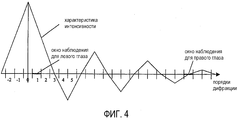
- фиг.4: характеристика интенсивности света в плоскости рассмотрения в зависимости от порядков дифракции света;- figure 4: the characteristic of the light intensity in the viewing plane, depending on the orders of diffraction of light;
- фиг.5: принципиальное изображение устройства для восстановления видеоголограмм с положением окна наблюдения для двух глаз наблюдателя в отношении порядков дифракции света во избежание смещения.- figure 5: a schematic image of a device for reconstructing video holograms with the position of the observation window for two eyes of the observer in relation to the orders of diffraction of light in order to avoid bias.
Устройство для восстановления видеоголограмм состоит из видеоголограммы, достаточно когерентного реального или виртуального точечного или линейного источника света и оптической системы. Сама видеоголограмма состоит из равномерно расположенных в виде матрицы или иным образом ячеек, содержащих, по меньшей мере, одно регулируемое по амплитуде и/или фазе отверстие на ячейку. Оптическая система восстановления видеоголограммы может быть известным образом реализована, например, просто оптической системой отображения, состоящей из точечного или линейного лазера и достаточно когерентного источника света.A device for reconstructing video holograms consists of a video hologram, a sufficiently coherent real or virtual point or linear light source, and an optical system. The video hologram itself consists of cells uniformly arranged in the form of a matrix or otherwise, containing at least one hole per cell, which is adjustable in amplitude and / or phase. An optical system for reconstructing a video hologram can be realized in a known manner, for example, simply by an optical display system consisting of a point or linear laser and a sufficiently coherent light source.
Принципиальное расположение видеоголограммы и восстановление изображены на фиг.1. В направлении света последовательно расположены источник 1 света, линза 2, голограмма 3 и плоскость 4 рассмотрения. Плоскость 4 рассмотрения соответствует плоскости Фурье обратного преобразования видеоголограммы с порядками дифракции света.The principal arrangement of the video hologram and restoration are depicted in figure 1. In the direction of light, a
Источник 1 света отображен оптической системой, которая представлена линзой 2, в которой отображается плоскость 4 рассмотрения. При установке голограммы 3 она изображается в плоскости 4 рассмотрения в виде обратного преобразования Фурье. Голограмма 3 с периодическими отверстиями создает равнорасположенные продолженные порядки дифракции в плоскости 4 рассмотрения, причем голографическое кодирование посредством так называемого эффекта обходной фазы происходит в сторону более высоких порядков дифракции света. Поскольку интенсивность уменьшается в сторону более высоких порядков дифракции света, в качестве окна 5 наблюдения выбирают, как правило, 1-й или -1-й порядок дифракции. Если это не указано особо, то для изложения изобретения ниже следует исходить из 1-го порядка дифракции.The
Протяженность восстановления была выбрана здесь так, что она по своей величине совпадает с интервалом периодичности 1-го порядка дифракции в плоскости 4 рассмотрения. Таким образом, более высокие порядки дифракции примыкают друг к другу без промежутка, но и без наложения.The recovery length was chosen here so that it coincides in magnitude with the interval of periodicity of the 1st diffraction order in the plane of 4 consideration. Thus, higher diffraction orders adjoin each other without a gap, but also without overlapping.
Выбранный 1-й порядок дифракции образует, правда, в виде образа Фурье восстановленную голограмму 3, однако не представляет собственно трехмерную картину 6. Она служит лишь в качестве окна 5 наблюдения, через которое можно рассматривать трехмерную картину 6 (фиг.2). Внутри светового пучка 1-го порядка дифракции собственно трехмерная картина 6 обозначена кружком. Сцена лежит, следовательно, внутри восстановленного конуса, образуемого голограммой 3 и окном 5 наблюдения. Картина возникает в виде образа Френеля голограммы, тогда как окно наблюдения является частью образа Фурье.The selected 1st diffraction order forms, however, in the form of a Fourier transform, the reconstructed
На фиг.3 показано голографическое кодирование. Трехмерная картина 6 построена из точек. Окно 5 наблюдения в качестве основы и выбранную точку 7 на картине 6 в качестве вершины конуса, проходящего через эту точку, проецируют на голограмму 3. Возникает область 8 проекции в видеоголограмме 3, в которой эта точка голографически кодируется. Для расчета фазовых значений можно определить длины волн от рассматриваемой точки 7 до ячеек голограммы 3. С этим восстановлением согласуют величину окна 5 наблюдения в интервале периодичности. Если бы, например, напротив, рассматриваемая точка 7 кодировалась во всей голограмме 3, то восстановление имело бы протяженность за пределами интервала периодичности. Зоны рассмотрения из соседних порядков дифракции накладывались бы друг на друга, причем наблюдатель видел бы периодическое продолжение рассматриваемой точки 7. Кодированная таким образом поверхность представлялась бы размытой по своим контурам из-за многократных наложений.Figure 3 shows holographic coding. Three-
Предпочтительным образом уменьшение интенсивности в сторону более высоких порядков дифракции используют для подавления смещений (перекрестных искажений) на другие окна наблюдения. На фиг.4 схематично изображена характеристика интенсивности света в зависимости от порядков дифракции, которая возникает за счет ширины отверстий в CGH. На абсциссе нанесены порядки дифракции. 1-й порядок дифракции представляет окно 5 наблюдения для левого глаза, т.е. левое окно наблюдения, через которое можно рассматривать трехмерную картину 6. Перекрестные искажения в окне наблюдения для правого глаза подавляются за счет уменьшения интенсивности в сторону более высоких порядков и дополнительно еще за счет нулевой точки распределения интенсивности.Preferably, a decrease in intensity towards higher diffraction orders is used to suppress biases (crosstalk) to other observation windows. Figure 4 schematically shows a characteristic of the light intensity depending on the diffraction orders, which occurs due to the width of the holes in the CGH. The abscissa shows the diffraction orders. The 1st diffraction order is the
Наблюдатель может рассматривать картину 6 голограммы 3, конечно, и обоими глазами (фиг.5). Для правого глаза был выбран в качестве правого окна 5' наблюдения -1-й порядок дифракции в соответствии с положением источника 1' света. Как видно из фиг.5, эта интенсивность смещена на левый глаз лишь с очень малым значением. Оно соответствует здесь -6-му порядку дифракции.The observer can consider the
Для левого глаза был выбран 1-й порядок дифракции в соответствии с положением источника 1 света. Здесь аналогичным образом возникает левое окно 5 наблюдения. Согласно изобретению, с помощью двух источников 1, 1' света соответствующие трехмерные картины 6, 6' (не показаны) изображают неподвижными по отношению к глазам. Для этого голограмму 3 при подключении источников 1, 1' света кодируют соответственно заново. В качестве альтернативы оба источника 1, 1' света могут восстановить одновременно голограмму 3 на обоих окнах 5, 5' наблюдения.For the left eye, the 1st diffraction order was selected in accordance with the position of the
При движении наблюдателя источники 1, 1' света сопровождают так, что оба окна 5, 5' наблюдения остаются локализованными в глаза наблюдателя. Это относится и к движениям по нормали, т.е. перпендикулярно видеоголограмме. Кроме того, одну трехмерную картину могут рассматривать также несколько наблюдателей за счет того, что при подключении дополнительных источников света возникают дополнительные окна наблюдения.When the observer moves, the
Claims (10)
Applications Claiming Priority (2)
| Application Number | Priority Date | Filing Date | Title |
|---|---|---|---|
| DE10253292 | 2002-11-13 | ||
| DE10253292.3 | 2002-11-13 |
Related Child Applications (1)
| Application Number | Title | Priority Date | Filing Date |
|---|---|---|---|
| RU2007105102/28A Division RU2363025C2 (en) | 2002-11-13 | 2003-11-11 | Video hologram and device for restoration of video holograms |
Publications (2)
| Publication Number | Publication Date |
|---|---|
| RU2005118086A RU2005118086A (en) | 2006-01-20 |
| RU2293365C2 true RU2293365C2 (en) | 2007-02-10 |
Family
ID=32308559
Family Applications (2)
| Application Number | Title | Priority Date | Filing Date |
|---|---|---|---|
| RU2007105102/28A RU2363025C2 (en) | 2002-11-13 | 2003-11-11 | Video hologram and device for restoration of video holograms |
| RU2005118086/28A RU2293365C2 (en) | 2002-11-13 | 2003-11-11 | Device for restoration of holograms |
Family Applications Before (1)
| Application Number | Title | Priority Date | Filing Date |
|---|---|---|---|
| RU2007105102/28A RU2363025C2 (en) | 2002-11-13 | 2003-11-11 | Video hologram and device for restoration of video holograms |
Country Status (13)
| Country | Link |
|---|---|
| US (14) | US7839548B2 (en) |
| EP (3) | EP2138911B1 (en) |
| JP (5) | JP4473133B2 (en) |
| KR (2) | KR100915431B1 (en) |
| CN (3) | CN101349889B (en) |
| AT (1) | ATE441877T1 (en) |
| BR (1) | BR0316222A (en) |
| DE (2) | DE10353439B4 (en) |
| HK (2) | HK1087198A1 (en) |
| IL (1) | IL168538A (en) |
| MX (1) | MXPA05005229A (en) |
| RU (2) | RU2363025C2 (en) |
| WO (1) | WO2004044659A2 (en) |
Cited By (1)
| Publication number | Priority date | Publication date | Assignee | Title |
|---|---|---|---|---|
| MD3896G2 (en) * | 2008-01-25 | 2009-12-31 | Государственный Университет Молд0 | Device for recovery of multiplex holograms |
Families Citing this family (124)
| Publication number | Priority date | Publication date | Assignee | Title |
|---|---|---|---|---|
| GB9903032D0 (en) * | 1999-02-11 | 1999-03-31 | Symbian Ltd | Messaging architecture |
| RU2363025C2 (en) * | 2002-11-13 | 2009-07-27 | Сириал Текнолоджиз Гмбх | Video hologram and device for restoration of video holograms |
| DE102004044111B4 (en) * | 2004-09-08 | 2015-05-07 | Seereal Technologies Gmbh | Method and device for coding and reconstructing computer-generated video holograms |
| DE102004063838A1 (en) | 2004-12-23 | 2006-07-06 | Seereal Technologies Gmbh | Method and apparatus for calculating computer generated video holograms |
| DE102005021155B3 (en) | 2005-04-29 | 2006-11-23 | Seereal Technologies Gmbh | Controllable lighting device |
| KR101263968B1 (en) | 2005-05-06 | 2013-05-13 | 씨리얼 테크놀로지스 게엠베하 | Device for holographic reconstruction of three-dimensional scenes |
| CN101347003B (en) * | 2005-12-22 | 2010-08-11 | 视瑞尔技术公司 | Method for the multimodal representation of image contents on a display unit for video holograms, and multimodal display unit |
| KR101367573B1 (en) | 2005-12-22 | 2014-02-25 | 시리얼 테크놀로지즈 에스.에이. | Method for the compensation of an inhomogeneous brightness perception in holographically reconstructed scenes |
| DE102006003741B4 (en) * | 2006-01-18 | 2009-08-27 | Seereal Technologies S.A. | Method for coding a computer-generated hologram |
| DE102006004301A1 (en) * | 2006-01-20 | 2007-08-02 | Seereal Technologies S.A. | Method for supportive calculation of division of resources in technical network |
| DE102006018689A1 (en) * | 2006-04-13 | 2007-10-25 | Seereal Technologies S.A. | Method for rendering and generating computer-generated video holograms in real time |
| DE102006024356B4 (en) * | 2006-05-19 | 2016-09-29 | Seereal Technologies S.A. | Holographic projection apparatus for reconstructing scenes and methods for holographic reconstruction |
| DE102006042324B4 (en) * | 2006-09-01 | 2014-06-18 | Seereal Technologies S.A. | Method for generating computer-generated video holograms in real time by means of sub-holograms |
| US20100073744A1 (en) | 2006-09-01 | 2010-03-25 | Seereal Technologies S.A. | Method for Generating Video Holograms in Real Time by Means of Subholograms |
| WO2008025842A1 (en) | 2006-09-01 | 2008-03-06 | Seereal Technologies S.A. | Interface and circuit arrangement, in particular for holographic encoding units or holographic reproduction devices |
| US8218210B2 (en) | 2006-09-01 | 2012-07-10 | Seereal Technologies S.A. | Method for generating computer-generated video holograms in real time by means of propagation |
| DE102006041637B4 (en) * | 2006-09-05 | 2010-11-25 | Seereal Technologies S.A. | A playback device and method for tracking a viewer window |
| DE102006042467A1 (en) * | 2006-09-09 | 2008-03-27 | Seereal Technologies S.A. | Method and device for coding computer-generated holograms in pixelated light modulators |
| DE102006043297B4 (en) * | 2006-09-14 | 2010-12-09 | Seereal Technologies S.A. | A playback apparatus and method comprising means for tracking a viewer window |
| DE102007024237B4 (en) | 2007-05-21 | 2009-01-29 | Seereal Technologies S.A. | Holographic reconstruction system with optical waveguide tracking |
| TWI421540B (en) * | 2006-10-26 | 2014-01-01 | Seereal Technologies Sa | Universal image display device and method (1) |
| DE102007024236A1 (en) | 2007-05-21 | 2008-11-27 | Seereal Technologies S.A. | Holographic reconstruction system with an array of controllable microprisms |
| GB0709379D0 (en) * | 2007-05-16 | 2007-06-27 | Seereal Technologies Sa | Smart display extended |
| TWI403868B (en) * | 2006-10-26 | 2013-08-01 | Seereal Technologies Sa | Holographic display device and method |
| JP2010507823A (en) * | 2006-10-26 | 2010-03-11 | シーリアル テクノロジーズ ソシエテ アノニム | Small holographic display device |
| WO2008049912A1 (en) * | 2006-10-26 | 2008-05-02 | Seereal Technologies S.A. | Holographic display device |
| DE102006062377B4 (en) | 2006-12-19 | 2018-03-22 | Seereal Technologies S.A. | Method and holographic display device for reducing speckle |
| DE102006062376B4 (en) | 2006-12-19 | 2018-03-22 | Seereal Technologies S.A. | Method and display device for reducing speckle |
| DE102006062413A1 (en) * | 2006-12-21 | 2008-06-26 | Seereal Technologies S.A. | Holographic projection device for enlarging a visibility region |
| DE102007005822A1 (en) | 2007-01-31 | 2008-08-07 | Seereal Technologies S.A. | Holographic reconstruction system with optical wave tracking |
| DE102007005823A1 (en) | 2007-01-31 | 2008-08-07 | Seereal Technologies S.A. | Optical wavefront correction for a holographic projection system |
| DE102007011560A1 (en) | 2007-03-02 | 2008-09-04 | Seereal Technologies S.A. | Device for minimizing the bending dispersion in light modulators comprises a refractive optical element assigned to a light modulator |
| DE102007011561B4 (en) * | 2007-03-02 | 2016-03-17 | Seereal Technologies S.A. | Device for correcting the wavelength dependence in diffraction-based optical systems |
| DE102007018266A1 (en) | 2007-04-10 | 2008-10-16 | Seereal Technologies S.A. | Holographic projection system with optical waveguide tracking and means for correcting the holographic reconstruction |
| DE102007023785B4 (en) * | 2007-05-16 | 2014-06-18 | Seereal Technologies S.A. | Analytical method for calculating video holograms in real time and holographic display device |
| DE102007023738A1 (en) * | 2007-05-16 | 2009-01-08 | Seereal Technologies S.A. | Method and device for reconstructing a three-dimensional scene in a holographic display |
| DE102007023739B4 (en) * | 2007-05-16 | 2018-01-04 | Seereal Technologies S.A. | Method for rendering and generating color video holograms in real time and holographic display device |
| US9581965B2 (en) | 2007-05-16 | 2017-02-28 | Seereal Technologies S.A. | Analytic method for computing video holograms in real time |
| DE102007023737B4 (en) | 2007-05-16 | 2009-01-02 | Seereal Technologies S.A. | Method for generating video holograms in real time for extending a 3D rendering graphics pipeline |
| DE102007023740B4 (en) | 2007-05-16 | 2009-04-09 | Seereal Technologies S.A. | Method for generating video holograms for a holographic display device with random addressing |
| GB0718629D0 (en) | 2007-05-16 | 2007-11-07 | Seereal Technologies Sa | Holograms |
| US8218211B2 (en) | 2007-05-16 | 2012-07-10 | Seereal Technologies S.A. | Holographic display with a variable beam deflection |
| DE102007025069B4 (en) | 2007-05-21 | 2018-05-24 | Seereal Technologies S.A. | Holographic reconstruction system |
| DE102007024235B4 (en) * | 2007-05-21 | 2009-04-30 | Seereal Technologies S.A. | Holographic reconstruction system and method with extended visibility range |
| DE102007028371B4 (en) | 2007-06-13 | 2012-05-16 | Seereal Technologies S.A. | Device for light modulation |
| DE102007036127A1 (en) | 2007-07-27 | 2009-01-29 | Seereal Technologies S.A. | Holographic reconstruction device |
| GB0716829D0 (en) * | 2007-08-31 | 2007-10-10 | Seereal Technologies Sa | Holographic display |
| DE102007045332B4 (en) * | 2007-09-17 | 2019-01-17 | Seereal Technologies S.A. | Holographic display for reconstructing a scene |
| WO2009050294A2 (en) * | 2007-10-19 | 2009-04-23 | Seereal Technologies S.A. | Light modulating device |
| GB0720484D0 (en) * | 2007-10-19 | 2007-11-28 | Seereal Technologies Sa | Cells |
| DE102007051521A1 (en) | 2007-10-19 | 2009-04-23 | Seereal Technologies S.A. | Dynamic Waveform Unit |
| GB2454246B (en) | 2007-11-02 | 2010-03-10 | Light Blue Optics Ltd | Holographic image display systems |
| DE102008000116A1 (en) | 2008-01-21 | 2009-07-30 | Seereal Technologies S.A. | Illumination unit for a holographic reconstruction system |
| DE102008000589B4 (en) | 2008-03-11 | 2018-02-01 | Seereal Technologies S.A. | Method for coding computer-generated holograms in pixelated light modulators |
| DE102008002692B4 (en) | 2008-06-26 | 2019-02-21 | Seereal Technologies S.A. | Display device for three-dimensional holographic or stereoscopic display of spatial objects and method for determining an apodization function for an apodisation mask |
| GB2461894B (en) * | 2008-07-16 | 2010-06-23 | Light Blue Optics Ltd | Holographic image display systems |
| DE102008040581B4 (en) * | 2008-07-21 | 2017-06-01 | Seereal Technologies S.A. | Controllable light modulation device |
| USD624952S1 (en) | 2008-10-20 | 2010-10-05 | X6D Ltd. | 3D glasses |
| USD603445S1 (en) | 2009-03-13 | 2009-11-03 | X6D Limited | 3D glasses |
| USD666663S1 (en) | 2008-10-20 | 2012-09-04 | X6D Limited | 3D glasses |
| USRE45394E1 (en) | 2008-10-20 | 2015-03-03 | X6D Limited | 3D glasses |
| CA2684513A1 (en) * | 2008-11-17 | 2010-05-17 | X6D Limited | Improved performance 3d glasses |
| US8542326B2 (en) | 2008-11-17 | 2013-09-24 | X6D Limited | 3D shutter glasses for use with LCD displays |
| DE102008054438A1 (en) | 2008-12-09 | 2010-06-24 | Seereal Technologies S.A. | Optical component for deflecting light rays passing through the optical component |
| USD646451S1 (en) | 2009-03-30 | 2011-10-04 | X6D Limited | Cart for 3D glasses |
| US8927801B2 (en) | 2009-04-13 | 2015-01-06 | The Procter & Gamble Company | Absorbent articles comprising wetness indicators |
| USD672804S1 (en) | 2009-05-13 | 2012-12-18 | X6D Limited | 3D glasses |
| USD650956S1 (en) | 2009-05-13 | 2011-12-20 | X6D Limited | Cart for 3D glasses |
| USD692941S1 (en) | 2009-11-16 | 2013-11-05 | X6D Limited | 3D glasses |
| USD669522S1 (en) | 2010-08-27 | 2012-10-23 | X6D Limited | 3D glasses |
| USD671590S1 (en) | 2010-09-10 | 2012-11-27 | X6D Limited | 3D glasses |
| USD662965S1 (en) | 2010-02-04 | 2012-07-03 | X6D Limited | 3D glasses |
| KR101929836B1 (en) | 2010-04-01 | 2018-12-18 | 시리얼 테크놀로지즈 에스.에이. | Method and device for encoding three-dimensional scenes which include transparent objects in a holographic system |
| KR102251546B1 (en) | 2010-07-06 | 2021-05-14 | 시리얼 테크놀로지즈 에스.에이. | Beam divergence and various collimators for holographic or stereoscopic displays |
| USD664183S1 (en) | 2010-08-27 | 2012-07-24 | X6D Limited | 3D glasses |
| KR101670927B1 (en) * | 2010-11-05 | 2016-11-01 | 삼성전자주식회사 | Display apparatus and method |
| US8913149B1 (en) | 2010-11-30 | 2014-12-16 | Integrity Applications Incorporated | Apparatus and techniques for enhanced resolution imaging |
| KR101993565B1 (en) | 2010-12-22 | 2019-06-26 | 시리얼 테크놀로지즈 에스.에이. | Combined light modulation device for tracking users |
| DE102011005154B4 (en) | 2010-12-22 | 2022-03-31 | Seereal Technologies S.A. | Light modulation device for a holographic or an autostereoscopic display |
| DE102011053037A1 (en) | 2011-08-26 | 2013-02-28 | Seereal Technologies S.A. | lighting device |
| KR101507202B1 (en) * | 2011-11-16 | 2015-04-08 | 엘지디스플레이 주식회사 | Spatial Light Modulating Panel Using Transparent Type Liquid Crystal Display Panel And 3D Display Device Using The Same |
| DE102011056006B4 (en) | 2011-12-01 | 2016-03-10 | Seereal Technologies S.A. | Method for coding a hologram in a light modulation device |
| KR101841624B1 (en) * | 2012-01-25 | 2018-03-26 | 삼성전자주식회사 | Method and apparatus for generating fast 3d hologram |
| CN107664838B (en) | 2012-01-26 | 2020-10-02 | 视瑞尔技术公司 | Display with observer tracking function |
| US9581966B1 (en) | 2012-02-15 | 2017-02-28 | Integrity Applications Incorporated | Systems and methodologies related to 3-D imaging and viewing |
| US9934614B2 (en) | 2012-05-31 | 2018-04-03 | Microsoft Technology Licensing, Llc | Fixed size augmented reality objects |
| US9354606B1 (en) | 2012-07-31 | 2016-05-31 | Integrity Applications Incorporated | Systems and methodologies related to generating projectable data for 3-D viewing |
| USD711959S1 (en) | 2012-08-10 | 2014-08-26 | X6D Limited | Glasses for amblyopia treatment |
| US9219905B1 (en) | 2012-08-31 | 2015-12-22 | Integrity Applications Incorporated | Systems and methodologies related to formatting data for 3-D viewing |
| WO2014052547A1 (en) | 2012-09-26 | 2014-04-03 | The Procter & Gamble Company | Liquid-activated formulation with solvent-based binding matrix |
| AU2013237745A1 (en) | 2012-10-09 | 2014-04-24 | Aristocrat Technologies Australia Pty Limited | A gaming system and a method of gaming |
| CN103186090B (en) * | 2013-03-14 | 2015-08-26 | 北京工业大学 | The online reconstruction display system of digital hologram imaging and method |
| US9310769B2 (en) * | 2013-03-28 | 2016-04-12 | Disney Enterprises, Inc. | Coarse integral holographic display |
| KR102248266B1 (en) | 2013-06-06 | 2021-05-04 | 시리얼 테크놀로지즈 에스.에이. | Device and method for calculating holographic data |
| FR3015743A1 (en) * | 2013-12-23 | 2015-06-26 | Orange | METHOD OF PROCESSING A SEQUENCE OF HOLOGRAPHIC IMAGES, DEVICES, SIGNALS, DEVICES AND COMPUTER PROGRAM THEREFOR |
| KR102208960B1 (en) | 2014-04-09 | 2021-01-28 | 삼성전자주식회사 | Holographic display |
| US9473764B2 (en) | 2014-06-27 | 2016-10-18 | Microsoft Technology Licensing, Llc | Stereoscopic image display |
| KR20160027384A (en) * | 2014-08-29 | 2016-03-10 | 전자부품연구원 | Exhibition Apparatus using the Transparent Display and Hologram |
| DE102015101203B4 (en) | 2015-01-28 | 2021-06-17 | Seereal Technologies S.A. | Light modulating device and holographic display device |
| KR101800929B1 (en) | 2015-01-29 | 2017-11-23 | 한국전자통신연구원 | Method and apparatus for correcting distortion on holographic display |
| KR102384223B1 (en) | 2015-02-26 | 2022-04-07 | 삼성전자주식회사 | Method of generating light modulating signal for 3-dimensional image display, and method and apparatus for displaying 3-dimensional image |
| US10073263B2 (en) * | 2015-03-04 | 2018-09-11 | Oculus Vr, Llc | Sparse projection for a virtual reality system |
| DE102015205873A1 (en) | 2015-04-01 | 2016-10-06 | Seereal Technologies S.A. | Method for calculating holograms for holographic reconstruction of two-dimensional and / or three-dimensional scenes |
| CN105223796B (en) * | 2015-09-08 | 2018-09-11 | 北京邮电大学 | Hologram computational methods based on near-eye display device and device |
| WO2017114789A2 (en) | 2015-12-28 | 2017-07-06 | Seereal Technologies S.A. | Display device and method for optimizing the image quality |
| CN114296332A (en) | 2016-03-02 | 2022-04-08 | 视瑞尔技术公司 | Lighting device |
| DE112017002514A5 (en) | 2016-05-18 | 2019-04-25 | Seereal Technologies S.A. | PROCESS FOR GENERATING HOLOGRAMS |
| CN108020977A (en) * | 2016-10-28 | 2018-05-11 | 京东方科技集团股份有限公司 | Display device and its display methods |
| RU2650086C1 (en) | 2016-12-22 | 2018-04-06 | Самсунг Электроникс Ко., Лтд. | Holographic image display device and a method of operation of a control unit contained in it |
| US10969740B2 (en) | 2017-06-27 | 2021-04-06 | Nvidia Corporation | System and method for near-eye light field rendering for wide field of view interactive three-dimensional computer graphics |
| CN109581850B (en) * | 2017-09-29 | 2021-03-05 | 京东方科技集团股份有限公司 | Holographic display method and holographic display device |
| JP7344873B2 (en) | 2017-12-07 | 2023-09-14 | シーリアル テクノロジーズ ソシエテ アノニム | heads up display |
| CN108305320B (en) * | 2018-02-09 | 2021-06-04 | 重庆大学 | Self-adaptive sliding window reconstruction method for improving large-field holographic imaging quality |
| WO2020018899A1 (en) * | 2018-07-20 | 2020-01-23 | Flex-N-Gate Advanced Product Development, Llc | Animated 3d image multiplier |
| WO2020018878A1 (en) | 2018-07-20 | 2020-01-23 | Flex-N-Gate Advanced Product Development, Llc | Floating image generation |
| CN112888998A (en) | 2018-08-16 | 2021-06-01 | 视瑞尔技术公司 | Light modulation device |
| US11454928B2 (en) * | 2018-11-06 | 2022-09-27 | Samsung Electronics Co., Ltd. | Holographic display apparatus and method for providing expanded viewing window |
| WO2021257743A2 (en) * | 2020-06-16 | 2021-12-23 | Marsupial Holdings, Inc. | Diffractive optic reflex sight |
| US20230315014A1 (en) | 2020-08-10 | 2023-10-05 | Seereal Technologies S.A. | Apparatus and method for computing hologram data |
| KR102510926B1 (en) * | 2020-10-14 | 2023-03-16 | 울산과학기술원 | A system for designating holographic colors and method for designating holographic colors based on dithering mask |
| US11798370B2 (en) | 2020-10-26 | 2023-10-24 | Lnw Gaming, Inc. | Gaming machine and method with symbol array alteration |
| KR20220133675A (en) * | 2021-03-25 | 2022-10-05 | 현대자동차주식회사 | Pop Up Floating Type Hologram System and Vehicle Thereof |
| US11907435B1 (en) | 2021-08-02 | 2024-02-20 | Omar Kevin Ubilla | Transformable apparatus with retractable display |
| WO2024058438A1 (en) * | 2022-09-15 | 2024-03-21 | 삼성전자 주식회사 | Electronic device providing holographic image and operating method of electronic device |
Family Cites Families (112)
| Publication number | Priority date | Publication date | Assignee | Title |
|---|---|---|---|---|
| US4028323A (en) * | 1968-02-19 | 1977-06-07 | Ciba-Geigy Ag | Process for making azo compounds by coupling with nitrosated heterocyclic primary amines |
| US3635726A (en) * | 1968-09-20 | 1972-01-18 | Griffith Laboratories | Method of producing soy protein concentrates |
| US3966982A (en) * | 1973-06-18 | 1976-06-29 | Dravo Corporation | Process and apparatus for treating oleaginous seed material |
| US3957353A (en) * | 1974-03-08 | 1976-05-18 | The Board Of Trustees Of The Leland Stanford University | Multiemulsion transparency providing separate phase and amplitude control |
| US3897574A (en) * | 1974-03-21 | 1975-07-29 | Central Soya Co | Purification of ethanol extractant in soy protein concentrate process |
| US4188399A (en) * | 1974-12-23 | 1980-02-12 | Miles Laboratories, Inc. | Process for preparing a heat coagulable viscous protein |
| CA1066329A (en) * | 1976-03-16 | 1979-11-13 | Edward J. Falk | Tandem brake master cylinder |
| US4285862A (en) * | 1976-09-30 | 1981-08-25 | General Foods, Limited | Protein isolate product |
| US4072670A (en) * | 1976-10-26 | 1978-02-07 | Mead Johnson & Company | Low phytate isoelectric precipitated soy protein isolate |
| US4091120A (en) * | 1976-11-15 | 1978-05-23 | Mead Johnson & Company | Liquid dietary product containing soy protein membrane isolate |
| US4151828A (en) * | 1977-06-28 | 1979-05-01 | Solarpower, Inc. | Solar energy collection tube |
| US4321280A (en) * | 1977-12-01 | 1982-03-23 | General Foods Corporation | Textured oil seed protein products |
| US4284656A (en) * | 1979-12-14 | 1981-08-18 | Hwa Stephen C P | Novel protein curd product and process of preparation |
| US4346122A (en) * | 1980-12-29 | 1982-08-24 | A. E. Staley Manufacturing Company | Low-viscosity, high-NSI, heat-gelling soy isolates |
| US4435438A (en) * | 1980-12-29 | 1984-03-06 | A. E. Staley Manufacturing Company | Soy isolate suitable for use in imitation cheese |
| US4368151A (en) * | 1981-08-10 | 1983-01-11 | A. E. Staley Manufacturing Company | 7S And 11S vegetable protein fractionation and isolation |
| US4460613A (en) * | 1982-11-01 | 1984-07-17 | Ralston Purina Company | Basal material for the preparation of tofu |
| US4530788A (en) * | 1982-12-03 | 1985-07-23 | Stauffer Chemical Company | Oil seed proteins evidencing improved functionality |
| US4500454A (en) * | 1982-12-03 | 1985-02-19 | Stauffer Chemical Company | Vegetable protein evidencing improved solution viscosity |
| US4493854A (en) * | 1983-09-20 | 1985-01-15 | The United States Of America As Represented By The Secretary Of Agriculture | Production of defatted soybean products by supercritical fluid extraction |
| US5290959A (en) * | 1985-09-10 | 1994-03-01 | Vitamins, Inc. | Mass separation of materials |
| US5086166A (en) * | 1987-02-13 | 1992-02-04 | The Texas A&M University System | Protein foods and food ingredients and processes for producing them from defatted and undefatted oilseeds |
| US5097017A (en) * | 1989-12-20 | 1992-03-17 | Central Soya Company, Inc. | Process for making soy protein concentrate |
| US5172251A (en) | 1990-04-12 | 1992-12-15 | Massachusetts Institute Of Technology | Three dimensional display system |
| US5191449A (en) * | 1992-02-03 | 1993-03-02 | Cfc Applied Holographics | Animated holographic stereogram display |
| JPH0627864A (en) * | 1992-07-10 | 1994-02-04 | Fujitsu Ltd | Method and device for generating computer hologram |
| JPH0635391A (en) * | 1992-07-20 | 1994-02-10 | Fujitsu Ltd | Stereoscopic display device |
| JPH07261125A (en) * | 1994-03-24 | 1995-10-13 | Olympus Optical Co Ltd | Projection type image display device |
| US5798964A (en) * | 1994-08-29 | 1998-08-25 | Toshiba Corporation | FRAM, FRAM card, and card system using the same |
| JP2765489B2 (en) * | 1994-09-30 | 1998-06-18 | 不二製油株式会社 | Soy protein and its manufacturing method |
| JP2989115B2 (en) * | 1995-03-27 | 1999-12-13 | 浜松ホトニクス株式会社 | Stereoscopic display method and stereoscopic display device |
| CA2146811C (en) * | 1995-04-11 | 2003-07-01 | David Michael Moore Dean | Method and apparatus for presenting stereoscopic images |
| US5936069A (en) * | 1995-12-06 | 1999-08-10 | Iowa State University Research Foundation | Process for producing improved soy protein concentrate from genetically-modified soybeans |
| ES2120878B1 (en) * | 1996-01-05 | 1999-06-01 | Alejo Trevijano Jose Javier | ELECTRONIC STEREOSCOPIC SYSTEM. |
| EP0793152B1 (en) * | 1996-02-29 | 2007-06-06 | Hamamatsu Photonics K.K. | Holographic imaging and display apparatus and method |
| BR9708545A (en) * | 1996-04-09 | 1999-08-03 | Du Pont | Soy protein product method for making a soy protein product milk substitute product formulation for children nutritious beverage powder or liquid cheese paste bologna ham product frozen yogurt and dessert product |
| US6108440A (en) * | 1996-06-28 | 2000-08-22 | Sony Corporation | Image data converting method |
| JP3546618B2 (en) * | 1996-12-19 | 2004-07-28 | 不二製油株式会社 | How to make soy protein |
| US6171640B1 (en) * | 1997-04-04 | 2001-01-09 | Monsanto Company | High beta-conglycinin products and their use |
| JP3798511B2 (en) * | 1997-06-11 | 2006-07-19 | 浜松ホトニクス株式会社 | Computer generated hologram display |
| GB9713658D0 (en) * | 1997-06-28 | 1997-09-03 | Travis Adrian R L | View-sequential holographic display |
| GB2330471A (en) | 1997-10-15 | 1999-04-21 | Secr Defence | Production of moving images for holography |
| US6330088B1 (en) | 1998-02-27 | 2001-12-11 | Zebra Imaging, Inc. | Method and apparatus for recording one-step, full-color, full-parallax, holographic stereograms |
| US6710920B1 (en) * | 1998-03-27 | 2004-03-23 | Sanyo Electric Co., Ltd | Stereoscopic display |
| DE19825192A1 (en) * | 1998-06-05 | 1999-12-16 | Joerg Gutjahr | Projection screen |
| WO2000003309A1 (en) | 1998-07-10 | 2000-01-20 | Digilens Inc. | Projection system based on reconfigurable holographic optics |
| JP2000059822A (en) * | 1998-08-06 | 2000-02-25 | Toshiba Corp | Stereoscopic video display device |
| JP4026242B2 (en) * | 1998-08-19 | 2007-12-26 | 松下電器産業株式会社 | Optical 3D video display device |
| JP3505404B2 (en) * | 1998-10-16 | 2004-03-08 | 理想科学工業株式会社 | Hologram pattern determination device, determination method thereof, and recording medium |
| US6844458B2 (en) * | 1998-11-20 | 2005-01-18 | Ip Holdings, L.L.C. | Vegetable oil refining |
| EP1008919A1 (en) * | 1998-12-09 | 2000-06-14 | Communauté Européenne (CE) | Computer assisted holographic method and apparatus for reproducing three-dimensional images |
| GB2350962A (en) | 1999-06-09 | 2000-12-13 | Secr Defence Brit | Holographic displays |
| US6335043B1 (en) * | 1999-08-03 | 2002-01-01 | Haokui Jiang | Method for extracting soybean proteins using an enzyme |
| US6665100B1 (en) * | 1999-08-10 | 2003-12-16 | Zebra Imaging, Inc. | Autostereoscopic three dimensional display using holographic projection |
| US6677327B1 (en) * | 1999-11-24 | 2004-01-13 | Archer-Daniels-Midland Company | Phytosterol and phytostanol compositions |
| IL134701A0 (en) * | 2000-02-23 | 2001-04-30 | J P M E D Ltd | Homogeneous solid matrix containing vegetable proteins |
| DE10008710C2 (en) * | 2000-02-24 | 2002-01-10 | Loh Optikmaschinen Ag | Device for centering clamping of optical lenses for their edge processing |
| GB2363273A (en) * | 2000-06-09 | 2001-12-12 | Secr Defence | Computation time reduction for three dimensional displays |
| WO2002013633A1 (en) * | 2000-08-11 | 2002-02-21 | Food & Packaging Centre Management Limited | Oil seed processing |
| IL154393A (en) * | 2000-08-18 | 2005-12-18 | Central Soya Co | Soy protein product and process for its manufacture |
| CN2439045Y (en) * | 2000-08-31 | 2001-07-11 | 深圳市泛彩溢实业有限公司 | Holographic liquid crystal display |
| EP1323352B1 (en) * | 2000-09-29 | 2007-06-13 | Fuji Oil Company, Ltd. | Process for producing soybean protein |
| GB0027103D0 (en) * | 2000-11-07 | 2000-12-20 | Secr Defence | Improved 3D display |
| JP2002149045A (en) * | 2000-11-15 | 2002-05-22 | Victor Co Of Japan Ltd | Hologram recording medium |
| US6630195B1 (en) * | 2000-11-21 | 2003-10-07 | Cargill, Incorporated | Process for producing oilseed protein products |
| US20040161513A1 (en) * | 2000-11-30 | 2004-08-19 | Kraft Foods Holdings, Inc. | Method of preparation of high quality soy-containing meat and meat analog products |
| US7175869B2 (en) * | 2000-11-30 | 2007-02-13 | Kraft Foods Holdings, Inc. | Method of deflavoring soy-derived materials using electrodialysis |
| US7037547B2 (en) * | 2000-11-30 | 2006-05-02 | Kraft Foods Holdings, Inc. | Method of deflavoring soy-derived materials for use in beverages |
| US6787173B2 (en) * | 2000-11-30 | 2004-09-07 | Kraft Foods Holdings, Inc. | Method of deflavoring soy-derived materials |
| US7045163B2 (en) * | 2000-11-30 | 2006-05-16 | Kraft Foods Holdings, Inc. | Method of deflavoring soy-derived materials |
| US20040161512A1 (en) * | 2000-11-30 | 2004-08-19 | Kraft Foods Holdings, Inc. | Method of deflavoring soy-derived materials for use in dough-based and baked products |
| US20040170743A1 (en) * | 2000-11-30 | 2004-09-02 | Kraft Foods Holdings, Inc. | Method of deflavoring soy-derived materials confectionary type products |
| US6576253B2 (en) * | 2000-12-05 | 2003-06-10 | Pbm Pharmaceuticals, Inc. | Food bars containing nutritional supplements |
| JP4632331B2 (en) | 2000-12-19 | 2011-02-16 | 大日本印刷株式会社 | Method for producing hologram master for optical duplication |
| EP1408770A2 (en) * | 2001-01-16 | 2004-04-21 | Solae, Llc | Gelling vegetable protein |
| KR100425293B1 (en) * | 2001-02-01 | 2004-03-30 | 삼성전자주식회사 | Stereoscopic display device |
| BR0207386B1 (en) * | 2001-02-20 | 2014-08-05 | Solae Llc | Process for producing a soy protein product, soy protein product and meat or dairy analogue |
| US8741356B2 (en) * | 2001-05-04 | 2014-06-03 | Burcon Nutrascience (Mb) Corp. | Production of oil seed protein isolate |
| GB2379351A (en) * | 2001-09-04 | 2003-03-05 | Holographic Imaging Llc | Illuminating a computer generated hologram |
| US20030059514A1 (en) * | 2001-09-10 | 2003-03-27 | Villagran Francisco Valentino | Compositions comprising soy protein and processes of their preparation |
| US20070015910A1 (en) * | 2001-11-20 | 2007-01-18 | Barker Larry D | Continuous process for production of oil seed protein isolate |
| US7090863B2 (en) * | 2001-11-30 | 2006-08-15 | Inpharma S.A. | Hypocholesterolemic composition and methods of use |
| CN100382717C (en) * | 2001-12-13 | 2008-04-23 | 伯康营养科学(Mb)公司 | Enhanced oil seed protein recovery |
| AU2003228911A1 (en) * | 2002-05-07 | 2003-11-11 | Solae, Llc | Low isoflavones, high saponins soy protein product and process for producing the same |
| BRPI0311991B8 (en) * | 2002-06-21 | 2020-05-19 | Burcon Nutrascience Mb Corp | process of preparing a canola protein isolate |
| GB2391475B (en) * | 2002-08-10 | 2005-02-02 | Reckitt Benckiser | A packaged hair-removing layer, its manufacture and its use |
| RU2363025C2 (en) * | 2002-11-13 | 2009-07-27 | Сириал Текнолоджиз Гмбх | Video hologram and device for restoration of video holograms |
| US20060019017A1 (en) * | 2002-12-09 | 2006-01-26 | Navpreet Singh | Soy protein concentrate with high gel strength and the process for making the same |
| US7018668B2 (en) * | 2003-02-06 | 2006-03-28 | Procter & Gamble Co. | Low fat creamer compositions |
| CN1771470B (en) * | 2003-02-12 | 2010-09-29 | 大日本印刷株式会社 | Computer-generated hologram |
| JP2007508001A (en) * | 2003-06-20 | 2007-04-05 | バーコン ニュートラサイエンス (エムビー) コーポレイション | Oilseed meal preparation |
| US20050084470A1 (en) * | 2003-10-15 | 2005-04-21 | Unilever Home & Personal Care Usa, Division Of Conopco, Inc. | Skin care and cleansing compositions containing oil seed product |
| US20050095345A1 (en) * | 2003-11-04 | 2005-05-05 | Schillinger John A. | Soy products and soy product production methods and apparatus |
| US20070128323A1 (en) * | 2003-12-26 | 2007-06-07 | Setsuo Tsujii | Creams, whipped products thereof, dry powders thereof and process for producing the same |
| US20050220979A1 (en) * | 2004-04-02 | 2005-10-06 | Craig Baumer | High soy protein nuggets and applications in food products |
| GB2416108A (en) * | 2004-07-16 | 2006-01-18 | Solae Llc | Protein-containing dairy product |
| US7556836B2 (en) * | 2004-09-03 | 2009-07-07 | Solae, Llc | High protein snack product |
| US7169425B2 (en) * | 2004-09-17 | 2007-01-30 | Solae, Llc | Size exclusion chromatography process for the preparation of an improved soy protein-containing composition |
| US20060062889A1 (en) * | 2004-09-17 | 2006-03-23 | Solae, Llc. | Soy protein-containing composition |
| US20060121176A1 (en) * | 2004-12-06 | 2006-06-08 | Solae, Llc | Soy protein-containing composition having improved functionality |
| US7332192B2 (en) * | 2004-12-17 | 2008-02-19 | Solae, Llc | Soy protein isolate |
| DE102004063838A1 (en) * | 2004-12-23 | 2006-07-06 | Seereal Technologies Gmbh | Method and apparatus for calculating computer generated video holograms |
| US20070014896A1 (en) * | 2005-07-18 | 2007-01-18 | Wong Theodore M | Calcium containing soy protein isolate composition |
| US20070031577A1 (en) * | 2005-07-20 | 2007-02-08 | Novozymes A/S | Method for producing a soy protein product |
| US20070042106A1 (en) * | 2005-08-17 | 2007-02-22 | Solae, Llc | High Protein Food Bars Comprising Sugar Alcohols and Having Improved Texture and Shelf-Life |
| US20070042103A1 (en) * | 2005-08-17 | 2007-02-22 | Solae, Llc. | Isolated Soy Protein Having High Molecular Weight Protein Fractions and Low Molecular Weight Protein Fractions |
| US20070077345A1 (en) * | 2005-09-30 | 2007-04-05 | Borders Cheryl K | High-protein soy-wheat crisps |
| US20070092633A1 (en) * | 2005-10-25 | 2007-04-26 | Navpreet Singh | Soy protein product with a high sterol and tocopherol content and process for its manufacture |
| DE102007005822A1 (en) * | 2007-01-31 | 2008-08-07 | Seereal Technologies S.A. | Holographic reconstruction system with optical wave tracking |
| JP5206951B2 (en) * | 2008-06-24 | 2013-06-12 | 株式会社ニコン | Image display device |
| KR101759252B1 (en) * | 2011-01-21 | 2017-07-19 | 삼성전자주식회사 | Three-dimensional holographic display using active shutter |
| JP5903805B2 (en) * | 2011-08-31 | 2016-04-13 | ブラザー工業株式会社 | Developing apparatus and manufacturing method thereof |
-
2003
- 2003-11-11 RU RU2007105102/28A patent/RU2363025C2/en not_active IP Right Cessation
- 2003-11-11 EP EP09168975.2A patent/EP2138911B1/en not_active Expired - Lifetime
- 2003-11-11 EP EP03788795A patent/EP1563346B1/en not_active Expired - Lifetime
- 2003-11-11 CN CN2008100967419A patent/CN101349889B/en not_active Expired - Lifetime
- 2003-11-11 CN CN201210020062.XA patent/CN102520604B/en not_active Expired - Lifetime
- 2003-11-11 MX MXPA05005229A patent/MXPA05005229A/en active IP Right Grant
- 2003-11-11 EP EP09168963.8A patent/EP2138910B1/en not_active Expired - Lifetime
- 2003-11-11 RU RU2005118086/28A patent/RU2293365C2/en not_active IP Right Cessation
- 2003-11-11 KR KR1020087005127A patent/KR100915431B1/en active IP Right Grant
- 2003-11-11 CN CNB200380103105XA patent/CN100437393C/en not_active Expired - Lifetime
- 2003-11-11 BR BR0316222-2A patent/BR0316222A/en not_active Application Discontinuation
- 2003-11-11 DE DE10353439A patent/DE10353439B4/en not_active Expired - Lifetime
- 2003-11-11 US US10/534,877 patent/US7839548B2/en not_active Expired - Lifetime
- 2003-11-11 AT AT03788795T patent/ATE441877T1/en active
- 2003-11-11 KR KR1020057008370A patent/KR100891293B1/en active IP Right Grant
- 2003-11-11 DE DE50311875T patent/DE50311875D1/en not_active Expired - Lifetime
- 2003-11-11 WO PCT/DE2003/003791 patent/WO2004044659A2/en active Application Filing
- 2003-11-11 JP JP2004550657A patent/JP4473133B2/en not_active Expired - Lifetime
-
2005
- 2005-05-11 IL IL168538A patent/IL168538A/en not_active IP Right Cessation
-
2006
- 2006-06-21 HK HK06107036.5A patent/HK1087198A1/en not_active IP Right Cessation
- 2006-06-29 US US11/427,638 patent/US20060238843A1/en not_active Abandoned
- 2006-06-29 US US11/427,645 patent/US7924484B2/en not_active Expired - Lifetime
- 2006-06-29 US US11/427,629 patent/US8314981B2/en active Active
- 2006-06-29 US US11/427,649 patent/US20060238840A1/en not_active Abandoned
- 2006-06-29 US US11/427,644 patent/US7929189B2/en not_active Expired - Lifetime
- 2006-06-29 US US11/427,640 patent/US7315408B2/en not_active Expired - Lifetime
- 2006-06-29 US US11/427,655 patent/US20060238844A1/en not_active Abandoned
-
2007
- 2007-11-09 US US11/937,991 patent/US8027071B2/en not_active Expired - Lifetime
-
2009
- 2009-06-30 HK HK09105855.4A patent/HK1128338A1/en not_active IP Right Cessation
-
2010
- 2010-01-18 JP JP2010008453A patent/JP5371801B2/en not_active Expired - Fee Related
- 2010-10-12 US US12/902,309 patent/US8174744B2/en not_active Expired - Fee Related
-
2011
- 2011-08-24 US US13/216,761 patent/US8384974B2/en not_active Expired - Lifetime
-
2013
- 2013-01-24 US US13/748,643 patent/US8941902B2/en not_active Expired - Lifetime
- 2013-03-15 JP JP2013054064A patent/JP5788427B2/en not_active Expired - Lifetime
-
2015
- 2015-01-08 US US14/592,227 patent/US9989920B2/en not_active Expired - Lifetime
- 2015-03-20 JP JP2015058246A patent/JP6249977B2/en not_active Expired - Lifetime
-
2017
- 2017-10-10 JP JP2017196995A patent/JP6701143B2/en not_active Expired - Lifetime
-
2018
- 2018-06-04 US US15/997,217 patent/US10884377B2/en not_active Expired - Lifetime
Non-Patent Citations (1)
| Title |
|---|
| TOMOYUKI MISHINA et al. Viewing - zone enlargement method for sampled hologram that uses high-order diffraction. Applied Optics. V.41, №8, р.1489-1499. * |
Cited By (1)
| Publication number | Priority date | Publication date | Assignee | Title |
|---|---|---|---|---|
| MD3896G2 (en) * | 2008-01-25 | 2009-12-31 | Государственный Университет Молд0 | Device for recovery of multiplex holograms |
Also Published As
Similar Documents
| Publication | Publication Date | Title |
|---|---|---|
| RU2293365C2 (en) | Device for restoration of holograms | |
| CA2577858C (en) | Method and device for encoding and reconstructing computer-generated video holograms | |
| Yamamoto | Visual system using ray-based image sensors and electronic holography display toward ultra-realistic communication | |
| Dai et al. | Electroholographic display with SLM |
Legal Events
| Date | Code | Title | Description |
|---|---|---|---|
| MG4A | Anticipatory lapse of an invention patent in the case of granting a patent on an identical invention | ||
| MM4A | The patent is invalid due to non-payment of fees |
Effective date: 20091112 |