EP2181361B1 - Holographic reconstruction device - Google Patents
Holographic reconstruction device Download PDFInfo
- Publication number
- EP2181361B1 EP2181361B1 EP08786426A EP08786426A EP2181361B1 EP 2181361 B1 EP2181361 B1 EP 2181361B1 EP 08786426 A EP08786426 A EP 08786426A EP 08786426 A EP08786426 A EP 08786426A EP 2181361 B1 EP2181361 B1 EP 2181361B1
- Authority
- EP
- European Patent Office
- Prior art keywords
- scene
- reconstruction
- object points
- object point
- points
- Prior art date
- Legal status (The legal status is an assumption and is not a legal conclusion. Google has not performed a legal analysis and makes no representation as to the accuracy of the status listed.)
- Active
Links
- 238000003384 imaging method Methods 0.000 claims abstract description 9
- 238000000034 method Methods 0.000 claims description 36
- 210000001747 pupil Anatomy 0.000 claims description 25
- 239000003086 colorant Substances 0.000 claims description 14
- 238000004088 simulation Methods 0.000 claims description 14
- 230000001427 coherent effect Effects 0.000 claims description 13
- 239000011295 pitch Substances 0.000 claims 4
- 238000004364 calculation method Methods 0.000 abstract description 12
- 230000006870 function Effects 0.000 description 14
- 230000001066 destructive effect Effects 0.000 description 8
- 235000015241 bacon Nutrition 0.000 description 7
- 238000005259 measurement Methods 0.000 description 6
- 230000009467 reduction Effects 0.000 description 5
- 238000012935 Averaging Methods 0.000 description 4
- 230000008859 change Effects 0.000 description 3
- 238000000354 decomposition reaction Methods 0.000 description 3
- 230000000694 effects Effects 0.000 description 3
- 230000003287 optical effect Effects 0.000 description 3
- 238000005070 sampling Methods 0.000 description 3
- 230000008569 process Effects 0.000 description 2
- 230000002123 temporal effect Effects 0.000 description 2
- 230000004304 visual acuity Effects 0.000 description 2
- 230000004075 alteration Effects 0.000 description 1
- 210000004556 brain Anatomy 0.000 description 1
- 238000010276 construction Methods 0.000 description 1
- 238000013461 design Methods 0.000 description 1
- 238000009792 diffusion process Methods 0.000 description 1
- 238000006073 displacement reaction Methods 0.000 description 1
- 230000004424 eye movement Effects 0.000 description 1
- 238000001093 holography Methods 0.000 description 1
- 230000003993 interaction Effects 0.000 description 1
- 238000013507 mapping Methods 0.000 description 1
- 230000004048 modification Effects 0.000 description 1
- 238000012986 modification Methods 0.000 description 1
- 230000008447 perception Effects 0.000 description 1
- 238000012545 processing Methods 0.000 description 1
- 230000004044 response Effects 0.000 description 1
- 238000000926 separation method Methods 0.000 description 1
Images


Classifications
-
- G—PHYSICS
- G03—PHOTOGRAPHY; CINEMATOGRAPHY; ANALOGOUS TECHNIQUES USING WAVES OTHER THAN OPTICAL WAVES; ELECTROGRAPHY; HOLOGRAPHY
- G03H—HOLOGRAPHIC PROCESSES OR APPARATUS
- G03H1/00—Holographic processes or apparatus using light, infrared or ultraviolet waves for obtaining holograms or for obtaining an image from them; Details peculiar thereto
- G03H1/32—Systems for obtaining speckle elimination
-
- G—PHYSICS
- G03—PHOTOGRAPHY; CINEMATOGRAPHY; ANALOGOUS TECHNIQUES USING WAVES OTHER THAN OPTICAL WAVES; ELECTROGRAPHY; HOLOGRAPHY
- G03H—HOLOGRAPHIC PROCESSES OR APPARATUS
- G03H1/00—Holographic processes or apparatus using light, infrared or ultraviolet waves for obtaining holograms or for obtaining an image from them; Details peculiar thereto
- G03H1/04—Processes or apparatus for producing holograms
- G03H1/08—Synthesising holograms, i.e. holograms synthesized from objects or objects from holograms
- G03H1/0808—Methods of numerical synthesis, e.g. coherent ray tracing [CRT], diffraction specific
-
- G—PHYSICS
- G03—PHOTOGRAPHY; CINEMATOGRAPHY; ANALOGOUS TECHNIQUES USING WAVES OTHER THAN OPTICAL WAVES; ELECTROGRAPHY; HOLOGRAPHY
- G03H—HOLOGRAPHIC PROCESSES OR APPARATUS
- G03H1/00—Holographic processes or apparatus using light, infrared or ultraviolet waves for obtaining holograms or for obtaining an image from them; Details peculiar thereto
- G03H1/22—Processes or apparatus for obtaining an optical image from holograms
- G03H1/2249—Holobject properties
-
- G—PHYSICS
- G03—PHOTOGRAPHY; CINEMATOGRAPHY; ANALOGOUS TECHNIQUES USING WAVES OTHER THAN OPTICAL WAVES; ELECTROGRAPHY; HOLOGRAPHY
- G03H—HOLOGRAPHIC PROCESSES OR APPARATUS
- G03H1/00—Holographic processes or apparatus using light, infrared or ultraviolet waves for obtaining holograms or for obtaining an image from them; Details peculiar thereto
- G03H1/22—Processes or apparatus for obtaining an optical image from holograms
- G03H1/2294—Addressing the hologram to an active spatial light modulator
-
- G—PHYSICS
- G03—PHOTOGRAPHY; CINEMATOGRAPHY; ANALOGOUS TECHNIQUES USING WAVES OTHER THAN OPTICAL WAVES; ELECTROGRAPHY; HOLOGRAPHY
- G03H—HOLOGRAPHIC PROCESSES OR APPARATUS
- G03H1/00—Holographic processes or apparatus using light, infrared or ultraviolet waves for obtaining holograms or for obtaining an image from them; Details peculiar thereto
- G03H1/22—Processes or apparatus for obtaining an optical image from holograms
- G03H1/2202—Reconstruction geometries or arrangements
- G03H2001/2236—Details of the viewing window
- G03H2001/2242—Multiple viewing windows
-
- G—PHYSICS
- G03—PHOTOGRAPHY; CINEMATOGRAPHY; ANALOGOUS TECHNIQUES USING WAVES OTHER THAN OPTICAL WAVES; ELECTROGRAPHY; HOLOGRAPHY
- G03H—HOLOGRAPHIC PROCESSES OR APPARATUS
- G03H1/00—Holographic processes or apparatus using light, infrared or ultraviolet waves for obtaining holograms or for obtaining an image from them; Details peculiar thereto
- G03H1/22—Processes or apparatus for obtaining an optical image from holograms
- G03H1/2249—Holobject properties
- G03H2001/2263—Multicoloured holobject
- G03H2001/2271—RGB holobject
-
- G—PHYSICS
- G03—PHOTOGRAPHY; CINEMATOGRAPHY; ANALOGOUS TECHNIQUES USING WAVES OTHER THAN OPTICAL WAVES; ELECTROGRAPHY; HOLOGRAPHY
- G03H—HOLOGRAPHIC PROCESSES OR APPARATUS
- G03H2210/00—Object characteristics
- G03H2210/40—Synthetic representation, i.e. digital or optical object decomposition
- G03H2210/45—Representation of the decomposed object
- G03H2210/452—Representation of the decomposed object into points
-
- G—PHYSICS
- G03—PHOTOGRAPHY; CINEMATOGRAPHY; ANALOGOUS TECHNIQUES USING WAVES OTHER THAN OPTICAL WAVES; ELECTROGRAPHY; HOLOGRAPHY
- G03H—HOLOGRAPHIC PROCESSES OR APPARATUS
- G03H2210/00—Object characteristics
- G03H2210/40—Synthetic representation, i.e. digital or optical object decomposition
- G03H2210/45—Representation of the decomposed object
- G03H2210/454—Representation of the decomposed object into planes
-
- G—PHYSICS
- G03—PHOTOGRAPHY; CINEMATOGRAPHY; ANALOGOUS TECHNIQUES USING WAVES OTHER THAN OPTICAL WAVES; ELECTROGRAPHY; HOLOGRAPHY
- G03H—HOLOGRAPHIC PROCESSES OR APPARATUS
- G03H2226/00—Electro-optic or electronic components relating to digital holography
- G03H2226/05—Means for tracking the observer
-
- G—PHYSICS
- G03—PHOTOGRAPHY; CINEMATOGRAPHY; ANALOGOUS TECHNIQUES USING WAVES OTHER THAN OPTICAL WAVES; ELECTROGRAPHY; HOLOGRAPHY
- G03H—HOLOGRAPHIC PROCESSES OR APPARATUS
- G03H2240/00—Hologram nature or properties
- G03H2240/50—Parameters or numerical values associated with holography, e.g. peel strength
- G03H2240/62—Sampling aspect applied to sensor or display
Landscapes
- Physics & Mathematics (AREA)
- General Physics & Mathematics (AREA)
- Holo Graphy (AREA)
Abstract
Description
Die Erfindung betrifft eine Einrichtung zum Erzeugen einer holographischen Rekonstruktion einer dreidimensionalen Szene, die aus einer Anzahl von Objekten besteht. Zum Berechnen und Kodieren von Hologrammen der Szene wird diese in einzelne Objektpunkte zerlegt, die zu Objektpunktgruppen zusammengestellt und als computergenerierte Hologramme (CGH) in einem Lichtmodulationsmittel dargestellt werden. Mittels kohärentem Licht und einem Rekonstruktionsmittel werden einzelne Rekonstruktionen von jeweils einer Objektpunktgruppe erzeugt und überlagert, wodurch ein Betrachter von einer Augenposition aus die Szene zeitlich gemittelt mit reduziertem Specklemuster sieht.The invention relates to a device for generating a holographic reconstruction of a three-dimensional scene, which consists of a number of objects. To compute and encode holograms of the scene, these are decomposed into individual object points, which are combined into object point groups and displayed as computer-generated holograms (CGH) in a light modulation means. By means of coherent light and a reconstruction means individual reconstructions of each one object point group are generated and superimposed, whereby a viewer sees from an eye position the scene averaged over time with reduced speckle pattern.
Die Erfindung betrifft ebenso ein Verfahren zum Erzeugen einer holographischen Rekonstruktion einer Szene, mit dem Specklemuster reduziert werden können.The invention also relates to a method for generating a holographic reconstruction of a scene with which speckle patterns can be reduced.
Anwendungsgebiet der Erfindung sind Einrichtungen, mit denen die Speicherung und Rekonstruktion komplexer Wellenfronten einer dreidimensionalen Szene durch Holographie unter Verwendung von kohärentem Laserlicht in Echtzeit oder echtzeitnah erfolgt und bei denen die Rekonstruktion von einem Sichtbarkeitsbereich aus, der auch als Betrachterfenster bezeichnet wird, zu sehen ist. Zur Modulation der Wellenfronten des einfallenden kohärenten Lichts mit den komplexen Werten der Szene ist ein Lichtmodulationsmittel mit steuerbaren Elementen vorgesehen.Fields of application of the invention are devices with which the storage and reconstruction of complex wavefronts of a three-dimensional scene by holography using coherent laser light in real time or close to real time and in which the reconstruction of a visibility area, which is also referred to as a viewer window, can be seen. To modulate the wavefronts of the incident coherent light with the complex values of the scene, a light modulation means with controllable elements is provided.
Ein spezieller Typ eines holographischen Displays, in welchem das erfindungsgemäße Verfahren angewendet werden kann, ist aus früheren Dokumenten der Anmelderin bekannt, z.B. aus (1)
Dort wird eine Hologrammberechnung auf folgender Grundlage durchgeführt: Eine dreidimensionale Szene wird zum Kodieren und holographischen Rekonstruieren in Schnittebenen zerlegt, die eine Vielzahl von Objektpunkten der Szene enthalten. Die Objektpunkte charakterisieren sowohl die Fläche als auch in der Summe aller Flächen die räumliche Szene. Sie werden in verschiedene steuerbare Elemente des Lichtmodulationsmittels mit komplexen Werten eingeschrieben bzw. kodiert und bilden im Lichtmodulationsmittel für jeden Objektpunkt einen separaten Bereich. Ein derartiger separater Bereich wird als das Subhologramm dieses Objektpunktes bezeichnet.There, a hologram computation is performed on the following basis: A three-dimensional scene is decomposed for encoding and holographic reconstruction into sectional planes containing a plurality of object points of the scene. The object points characterize both the area and in the sum of all areas the spatial scene. They are written into various controllable elements of the light modulation means with complex values, and form in the light modulation means for each Object point a separate area. Such a separate area is referred to as the sub-hologram of this object point.
Das Subhologramm entspricht ungefähr einer holographisch kodierten Linsenfunktion, die diesen einen Objektpunkt in ihrem Brennpunkt rekonstruiert. Der Betrag der komplexen Werte, also die Amplitude, ist über die Ausdehnung des Subhologramms ungefähr konstant und hängt in seiner Größe von der axialen Entfernung des Objektpunktes zum Bildschirm und von der Intensität des Objektpunktes ab.The sub-hologram corresponds approximately to a holographically coded lens function that reconstructs this one object point at its focal point. The amount of the complex values, ie the amplitude, is approximately constant over the extent of the sub-hologram and depends in its size on the axial distance of the object point to the screen and on the intensity of the object point.
Die Phasenverteilung der komplexen Werte im Bereich des Subhologramms entspricht ungefähr der Funktion einer Linse, deren Brennweite von der axialen Entfernung des Objektpunktes zum Lichtmodulationsmittel bzw. Bildschirm abhängt. Beim Durchgang von kohärentem Licht durch den Lichtmodulator verändern die komplexen Werte, die in die steuerbaren Elemente des Subhologramms eingeschriebenen sind, die Amplitude und/oder Phase des Lichts. Mit dem modulierten Licht kann der Objektpunkt rekonstruiert werden. Außerhalb des Subhologramms hat dieser Objektpunkt im Lichtmodulationsmittel den Wert Null. Das insgesamt kodierte Hologramm der Szene erhält man durch Aufaddieren der komplexen Werte der einzelnen Subhologramme.The phase distribution of the complex values in the region of the sub-hologram corresponds approximately to the function of a lens whose focal length depends on the axial distance of the object point to the light modulation means or screen. As coherent light passes through the light modulator, the complex values written to the controllable elements of the sub-hologram change the amplitude and / or phase of the light. With the modulated light, the object point can be reconstructed. Outside the sub-hologram, this object point has the value zero in the light modulation means. The overall coded hologram of the scene is obtained by adding up the complex values of the individual sub-holograms.
Die holographische Rekonstruktion der Szene wird durch ein Rekonstruktionsmittel in einem Rekonstruktionsraum erzeugt, der vom Sichtbarkeitsbereich und dem Lichtmodulationsmittel aufgespannt wird. Die von den kodierten Hologrammen der Szene ausgehenden Wellenfronten überlagern sich im Sichtbarkeitsbereich, so dass die rekonstruierten Objektpunkte dort von einer Augenposition aus zu sehen sind. Die Rekonstruktion aus den überlagerten modulierten Wellenfronten wird erzeugt, indem für jedes Auge eines Betrachters im Zeit- oder Raummultiplex unterschiedliche perspektivische Ansichten der Szene erzeugt werden, die sich in der Parallaxe unterscheiden, aber vom Gehirn als eine einzige holographische 3D-Darstellung gesehen werden.The holographic reconstruction of the scene is generated by a reconstruction means in a reconstruction space spanned by the visibility area and the light modulation means. The wavefronts emanating from the coded holograms of the scene are superimposed in the visibility range, so that the reconstructed object points can be seen there from an eye position. The reconstruction from the superimposed modulated wavefronts is generated by creating for each eye of a viewer in time or space multiplex different perspective views of the scene that differ in parallax but are seen by the brain as a single holographic 3D representation.
Zum Betrachten der Rekonstruktion der 3D-Szene kann der Betrachter entweder auf ein Lichtmodulationsmittel schauen, in welches ein Hologramm der Szene direkt kodiert ist und das als Bildschirm dient. Dies wird als Direktsichtaufbau bezeichnet.To view the reconstruction of the 3D scene, the viewer can either look at a light modulation means in which a hologram of the scene is directly encoded and which serves as a screen. This is called a direct-view setup.
Alternativ kann der Betrachter auf einen Bildschirm schauen, auf den entweder eine Abbildung oder eine Transformierte der im Lichtmodulationsmittel kodierten Hologrammwerte projiziert wird. Dies wird als Projektionsaufbau bezeichnet.Alternatively, the viewer may look at a screen onto which either an image or a transform of the hologram values encoded in the light modulation means is projected. This is called projection construction.
Die Augenpositionen von Betrachtern werden in bekannter Weise von einem Positionsfinder ermittelt, der programmtechnisch, das heißt softwaremäßig, mit einem Speichermittel und einer Recheneinheit sowie einem Systemsteuermittel gekoppelt ist. Im Speichermittel liegen auch die zur Berechnung des CGH der Szene benötigten Informationen der Objektpunkte in Datensätzen als Look-up-Tabelle gespeichert vor.The eye positions of observers are determined in a known manner by a position finder, which is program-technically, ie software-coupled, with a memory means and a computing unit and a system control means. In the storage means, the information of the object points required for calculating the CGH of the scene is also stored in data records as a look-up table.
Da auf dem Lichtmodulationsmittel nur eine diskrete Aufzeichnung möglich ist, erfolgt zur Hologrammberechnung eine diskrete Abtastung der Objektpunkte der Szene. Mit bestimmten Kodierverfahren ist es möglich, eine Rekonstruktion zu erzeugen, die am Ort der Abtastpunkte mit der abgetasteten Szene vollständig übereinstimmt. Die physikalische Rekonstruktion ergibt aber einen kontinuierlichen Verlauf der rekonstruierten Lichtintensität auch zwischen den Abtastpunkten. An diesen Orten treten Abweichungen vom Intensitätsverlauf in der Szene auf, die zu den Specklemustern der Rekonstruktion führen und die Qualität der holographischen Darstellung mindern. Dies ist besonders dann der Fall, wenn die Berechnung des Hologramms mit einer Zufallsphase der Objektpunkte durchgeführt wird.Since only a discrete recording is possible on the light modulation means, a discrete sampling of the object points of the scene takes place for the hologram calculation. With certain coding methods, it is possible to generate a reconstruction which completely coincides with the sampled scene at the location of the sampling points. However, the physical reconstruction yields a continuous course of the reconstructed light intensity also between the sampling points. At these locations deviations from the intensity curve in the scene occur which lead to the bacon patterns of the reconstruction and reduce the quality of the holographic representation. This is especially the case when the calculation of the hologram is performed with a random phase of the object points.
Man versteht allgemein unter einem Specklemuster ein granulationsartiges Interferenzmuster, das als eine räumliche Struktur mit zufällig verteilten Intensitätsminima und -maxima durch Interferenz vieler Lichtwellen mit statistisch unregelmäßig verteilten Phasendifferenzen entsteht. Diese Specklemuster stören die Qualität der Wahrnehmung der rekonstruierten Szene.A granular-like interference pattern is generally understood to be a speckle pattern that arises as a spatial structure with randomly distributed intensity minima and maxima due to the interference of many light waves with statistically irregularly distributed phase differences. These speckle patterns disturb the quality of perception of the reconstructed scene.
Ein Reduzieren der Specklemuster bei der Rekonstruktion der 3D-Szene kann prinzipiell durch zeitliche oder/und räumliche Mittelung erreicht werden. Dabei mittelt immer das Auge des Betrachters über mehrere ihm dargestellte Rekonstruktionen, von denen jede ein unterschiedliches Specklemuster aufweist. Das Specklemuster ist beispielsweise dann zufällig und unterschiedlich, wenn die Objektpunkte der Szene unterschiedliche Zufallsphasen aufweisen. Durch die Mittelung nimmt der Betrachter eine Verringerung des Specklemusters wahr.Reducing the speckle patterns in the reconstruction of the 3D scene can be achieved in principle by temporal and / or spatial averaging. In doing so, the eye of the beholder always averages several reconstructions shown to him, each of which has a different speckle pattern. For example, the speckle pattern is random and different if the object points of the scene have different random phases. By averaging, the viewer perceives a reduction in the speckle pattern.
So wird z.B. im Dokument von Donghyun Kim " Reduction of coherent artifacts in dynamic holografic three-dimensional displays by diffraction-specific pseudorandom diffusion" eine zeitliche Mittelung zur Reduzierung von Specklemustern beschrieben. Verschiedene Hologramme einer Szene werden nacheinander berechnet und dargestellt, wobei die einzelnen Objektpunkte der Szene mit unterschiedlichen relativen Phasendifferenzen überlagert werden. Dadurch mitteln die Augen zeitlich die Interferenzeffekte, also die Specklemuster, aus. Bei derartigen Verfahren muss man aber einen erhöhten Rechenaufwand durch die Berechnungen vieler Hologramme hinnehmen, da jedes Hologramm stets für alle Objektpunkte berechnet wird, was aber bei einer Echtzeitdarstellung von rekonstruierten Szenen nachteilig ist.For example, Described in the document by Donghyun Kim "Reduction of coherent artifacts in dynamic holographic three-dimensional displays by diffraction-specific pseudorandom diffusion" a temporal averaging for the reduction of bacon patterns. Various holograms of a scene are successively calculated and displayed, with the individual object points of the scene being superimposed with different relative phase differences. As a result, the eyes average the interference effects, ie the speckle patterns, over time. In such methods, however, one must take an increased amount of computation through the calculations of many holograms, since each hologram is always calculated for all object points, which is disadvantageous in a real-time representation of reconstructed scenes.
Zusätzlich werden preiswerte Lichtmodulationsmittel zur holographischen Wiedergabe mit schnelleren Schaltzeiten benötigt. Diese sind momentan aber nicht erhältlich.In addition, inexpensive light modulation means are needed for holographic reproduction with faster switching times. These are not available at the moment.
Weiterhin ist bei der Rekonstruktion einer Szene in einem holographischen Display das Auflösungsvermögen des menschlichen Auges zu beachten.Furthermore, when reconstructing a scene in a holographic display, the resolution of the human eye must be considered.
Damit flächige Anteile einer Szene von einem Betrachter auch als zusammenhängende Fläche wahrgenommen werden und nicht als eine Ansammlung von einzelnen Punkten, darf bei der rechnerischen Zerlegung der Szene in Objektpunkte innerhalb dieser Fläche bzw. Schnittebene ein bestimmter Abstand zwischen benachbarten Objektpunkten nicht überschritten werden. Insbesondere die zwischen nahe beieinander liegenden Objektpunkten auftretenden Interferenzen tragen aber zu einem großen Teil zu den Specklemustern bei, die beseitigt werden müssen.So that flat parts of a scene are also perceived by a viewer as a contiguous surface and not as a collection of individual points, a certain distance between adjacent object points must not be exceeded during the computational decomposition of the scene into object points within this surface or section plane. In particular, the interference occurring between closely spaced object points, however, contributes to a large extent to the bacon patterns which must be eliminated.
Es ist Aufgabe der Erfindung, das Berechnen und Kodieren von computergenerierten Hologrammen (CGH) einer Szene so zu gestalten, dass das Auftreten von Specklemustern bei der holographischen Rekonstruktion der Szene weitestgehend unterdrückt wird, ohne den Rechenaufwand zu erhöhen. Gleichzeitig soll in einer derart gestalteten holographischen Rekonstruktionseinrichtung die holographische Darstellung der Szene insgesamt in guter Qualität zu sehen sein.It is the object of the invention to design the computation and coding of computer-generated holograms (CGH) of a scene in such a way that the occurrence of speckle patterns in the holographic reconstruction of the scene is largely suppressed, without increasing the computational effort. At the same time, the holographic representation of the scene as a whole should be seen in good quality in such a designed holographic reconstruction device.
Das der Erfindung zugrunde liegende prinzipielle Verfahren zur Hologrammberechnung und holographischen Rekonstruktion einer dreidimensionalen Szene wird im Stand der Technik erklärt. Es basiert darauf, dass sich die Szene aus Objekten und diese wiederum aus Objektpunkten zusammensetzen. Zur Rekonstruktion der Szene sind verschiedene Mittel vorgesehen, die in Systemsteuermitteln vereint sind oder mit diesen zusammenwirken. Sie ermögliche, dass Objektpunkte ausgewählt und zu Objektpunktgruppen zusammengefasst werden und dass die Objektpunktgruppen als einzelne CGH berechnet und dargestellt werden können. Durch das Zusammenwirken der verschiedenen Mittel wird eine Überlagerung von Lichtwellenfronten der einzelnen Rekonstruktionen der Objektpunktgruppen erreicht, so dass die Augen eines Betrachters die resultierende Rekonstruktion der Szene in einer Augenposition sehen.The basic method of the invention for hologram calculation and holographic reconstruction of a three-dimensional scene is explained in the prior art. It is based on the fact that the scene is composed of objects and these in turn are object points. To reconstruct the scene, various means are provided, which are combined in system control means or interact with them. It allows object points to be selected and grouped into object point groups, and the object point groups to be calculated and displayed as a single CGH. The interaction of the various means achieves a superimposition of lightwave fronts of the individual object group reconstructions so that the eyes of an observer see the resulting reconstruction of the scene in an eye position.
Basierend auf diesem Prinzip wird die Aufgabe erfindungsgemäß durch eine Einrichtung gemäß Anspruch 11 gelöst, in der sowohl das Auswählen von Objektpunkten in den Schnittebenen anhand des Rasters als auch die Zusammenstellung der Objektpunkte zu Objektpunktgruppen durch Systemsteuermittel in Abhängigkeit von der sichtbaren Auflösung der Rekonstruktion der Szene erfolgt.Based on this principle, the object is achieved by a device according to claim 11, in which both the selection of object points in the cutting planes on the basis of the grid and the compilation of the object points to object point groups by system control means in response to the visible resolution of the reconstruction of the scene ,
Zum Anpassen an die sichtbare Auflösung der Rekonstruktion der Szene durch Systemsteuermittel
- ist in jeweils einer Schnittebene ein Rastermass für die Objektpunkte generiert, mit dem benachbarte Objektpunkte in der Schnittebene für den Betrachter nicht getrennt auflösbar sind, und
- erfolgt die Zusammenstellung von Objektpunkten der jeweiligen Schnittebene zu einer Objektpunktgruppe mit solchen Objektpunkten, die für den Betrachter getrennt auflösbar sind.
- in each case a grid dimension for the object points is generated in each of a sectional plane, with the adjacent object points in the sectional plane for the viewer can not be resolved separately, and
- the compilation of object points of the respective sectional plane to an object point group is carried out with such object points, which are separately resolvable for the viewer.
Auf diese Weise wird jeder Objektpunkt der zerlegten Szene für die Rekonstruktion ausgewählt. Dadurch wird vorteilhaft erreicht, dass jeder Objektpunkt nur einmal einer Objektpunktgruppe zugeordnet wird und weniger Hologramme von Objektpunktgruppen berechnet und kodiert werden müssen. Das führt neben dem Reduzieren von Specklemustern insgesamt auch zu einer Verkürzung der Rechenzeit.In this way, each object point of the decomposed scene is selected for reconstruction. As a result, it is advantageously achieved that each object point is assigned only once to an object point group and fewer holograms of object point groups have to be calculated and coded. That leads beside the Reducing bacon patterns overall also reduces computing time.
Erfindungsgemäß wird vorgeschlagen, die sichtbare Auflösung der Rekonstruktion der Szene an das Auflösungsvermögen des menschlichen Auges anzupassen.According to the invention, it is proposed to adapt the visible resolution of the reconstruction of the scene to the resolving power of the human eye.
Das Auflösungsvermögen des Auges wird durch eine Airy Funktion 2*j1(r-r0) / (r-r0) beschrieben, wobei mit r0 = (x0, y0) die Koordinate eines Objektpunktes und mit r-r0 der Abstand von dieser Koordinate innerhalb einer Schnittebene sowie mit j1 eine Besselfunktion bezeichnet sind.The resolution of the eye is described by an Airy function 2 * j1 (r-r0) / (r-r0), where r0 = (x0, y0) the coordinate of an object point and r-r0 the distance from this coordinate within a Section plane and j1 are called a Bessel function.
Zum Realisieren der Airy Funktion ist in der Einrichtung ein Positionsfinder zum Erfassen der Daten der aktuellen Augenposition mindestens eines Betrachters und der aktuellen Größe der Augenpupille dieses Betrachters vorgesehen. Weiterhin sind in der Einrichtung Recheneinheiten vorgesehen, um mit dem Abstand der aktuellen Augenposition von der jeweiligen Schnittebene der Szene und dem aktuellen Pupillendurchmesser eines Betrachters eine Objektpunktdichte zu berechnen, mit der das Rastermaß für die Objektpunkte in der jeweiligen Schnittebene vom Systemsteuermittel bestimmt wird.In order to realize the Airy function, a position finder for acquiring the data of the current eye position of at least one observer and the current size of the eye pupil of this observer is provided in the device. Furthermore, computing units are provided in the device in order to use the distance of the current eye position from the respective sectional plane of the scene and the current pupil diameter of a viewer to calculate an object point density with which the grid dimension for the object points in the respective sectional plane is determined by the system control means.
Der aktuelle Pupillendurchmesser kann auch über einen Helligkeitswert ermittelt werden, indem der Positionsfinder einen Sensor zum Erfassen eines aktuellen Helligkeitswertes der zu rekonstruierenden Szene oder des Umgebungslichts in einem Rekonstruktionsraum aufweist.The current pupil diameter can also be determined via a brightness value in that the position finder has a sensor for detecting a current brightness value of the scene to be reconstructed or the ambient light in a reconstruction space.
Weiterhin kann erfindungsgemäß die sichtbare Auflösung der Rekonstruktion der Szene an die Abbildungseigenschaften des Rekonstruktionsmittels angepasst werden.Furthermore, according to the invention, the visible resolution of the reconstruction of the scene can be adapted to the imaging properties of the reconstruction means.
Dazu wird vorgeschlagen, die Abbildungseigenschaften des Rekonstruktionsmittels wahlweise durch eine Simulation oder aus einer Messkurve zu ermitteln. Hierbei kann für verschiedene Schnittebenen die Punktbildfunktion (english Point Spread Funktion, PSF) für eine Abbildung der Lichtquelle in die jeweilige Schnittebene mittels einer Kombination aus dem Rekonstruktionsmittel und einer im Lichtmodulationsmittel kodierten Linse entweder mit einer geeigneten Optik-Software berechnet oder experimentell ermittelt werden.For this purpose, it is proposed to determine the imaging properties of the reconstruction means either by a simulation or from a measurement curve. In this case, the point spread function (PSF) for a mapping of the light source into the respective cutting plane can be calculated or determined experimentally by means of a combination of the reconstruction means and a lens encoded in the light modulation means either with suitable optical software.
Insbesondere können die für die sichtbare Auflösung kennzeichnenden lateralen Abstände der Objektpunkte aus der Simulation oder der Messkurve entnommen und in den entsprechenden Datensätzen des Speichermittels gespeichert werden.In particular, the lateral distances of the object points which characterize the visible resolution can be taken from the simulation or the measurement curve and stored in the corresponding data records of the storage means.
Es ist weiterhin vorgesehen, dass die Systemsteuermittel die Objektpunkte in einer Schnittebene sowohl in Abhängigkeit von einer aktuellen Augenposition des Betrachters als auch in Abhängigkeit vom Auflösungsvermögen des Rekonstruktionsmittels auswählen und zu Objektpunktgruppen zusammenstellen.It is furthermore provided that the system control means select the object points in a sectional plane both as a function of a current eye position of the observer and as a function of the resolving power of the reconstruction means and assemble them into object point groups.
Die erfindungsgemäße Einrichtung ist weiterhin so gestaltet, dass die Systemsteuermittel das Kodieren der CGH im Lichtmodulationsmittel und das nachfolgende Rekonstruieren der Objektpunktgruppen der Szene steuern. Dabei sind die Objektpunktgruppen im Lichtmodulationsmittel zweidimensional kodiert. Sie können aber auch eindimensional im Lichtmodulationsmittel kodiert sein.The device according to the invention is further designed such that the system control means control the coding of the CGH in the light modulation means and the subsequent reconstruction of the object point groups of the scene. In this case, the object point groups are coded two-dimensionally in the light modulation means. However, they can also be coded one-dimensionally in the light modulation means.
Die Aufgabe der Erfindung wird ebenfalls durch ein Verfahren gemäß Anspruch 1 zum holographischen Rekonstruieren einer Szene gelöst, dessen Verfahrensschritte im Wesentlichen mit den bereits beschriebenen Mitteln der Einrichtung ausgeführt werden können.The object of the invention is also achieved by a method according to claim 1 for the holographic reconstruction of a scene whose method steps can be carried out substantially with the means already described of the device.
Das Verfahren ist dadurch gekennzeichnet, dass die Systemsteuermittel sowohl das Auswählen von Objektpunkten in den Schnittebenen anhand des Rasters als auch die Zusammenstellung der Objektpunkte zu Objektpunktgruppen in Abhängigkeit von der sichtbaren Auflösung der Rekonstruktion der Szene vornehmen.The method is characterized in that the system control means both make the selection of object points in the cutting planes on the basis of the grid and the combination of the object points to object point groups depending on the visible resolution of the reconstruction of the scene.
-
in jeweils einer Schnittebene ein Rastermaß für die Objektpunkte, mit dem benachbarte Objektpunkte in der Schnittebene für den Betrachter nicht getrennt auflösbar sind, und
stellen die Systemsteuermittelin each case a sectional plane, a grid dimension for the object points with which adjacent object points in the sectional plane can not be resolved separately for the viewer, and
put the system control means - diejenigen Objektpunkte der jeweiligen Schnittebene, die für den Betrachter getrennt auflösbar sind, zu einer Objektpunktgruppe zusammen.those object points of the respective cutting plane, which are separately resolvable for the viewer, together to form an object point group.
Der Verfahrensschritt der inkohärenten Überlagerung der einzelnen Rekonstruktionen kann zeitsequentiell ausgeführt werden, so dass die Augen des Betrachters zeitlich die Intensität der Rekonstruktion über die Summe der Intensitäten der einzelnen Rekonstruktionen mitteln.The process step of incoherent superimposition of the individual reconstructions can be carried out in a time-sequential manner so that the eyes of the observer averify the intensity of the reconstruction over the sum of the intensities of the individual reconstructions.
Es ist jedoch auch möglich, die inkohärente Überlagerung der einzelnen Rekonstruktionen gleichzeitig durchzuführen. Dazu besteht das Lichtmodulationsmittel aus mehreren Lichtmodulatoren, in die gleichzeitig ein CGH kodiert wird. Mit diesen CGH werden mit der entsprechenden Anzahl von Rekonstruktionsmitteln gleichzeitig mehrere einzelne Rekonstruktionen mit zueinander unterschiedlichen Specklemustern erzeugt und deren Lichtwellenfronten am Ort der Augenposition gleichzeitig überlagert.However, it is also possible to carry out the incoherent superimposition of the individual reconstructions simultaneously. For this purpose, the light modulation means consists of a plurality of light modulators, in which a CGH is simultaneously coded. With this CGH, several individual reconstructions with mutually different bacon patterns are generated simultaneously with the corresponding number of reconstruction means and their lightwave fronts are simultaneously superimposed at the location of the eye position.
Weiterhin kann die sichtbare Auflösung der Rekonstruktion der Szene an das Auflösungsvermögen des Lichtmodulationsmittels angepasst werden.Furthermore, the visible resolution of the reconstruction of the scene can be adapted to the resolution of the light modulation means.
In Ausgestaltung der Erfindung wird ein Verfahren zum holographischen Rekonstruieren einer farbigen Szene beschreiben, bei dem die Zerlegung der farbigen Szene in unterschiedliche Farbanteile programmtechnisch im Systemsteuermittel erfolgt und die farbige Rekonstruktion der Szene aus mindestens zwei unterschiedlichen einfarbigen Rekonstruktionen verschiedener Wellenlängen des Lichts erzeugt wird, wobei für jeden Farbanteil jeweils eine Zerlegung der Szene in Objektpunkte, eine Zusammenstellung der Objektpunkte zu Objektpunktgruppen und eine Berechnung der einfarbigen CGH separat erfolgt.In a refinement of the invention, a method for the holographic reconstruction of a colored scene is described in which the color scene is divided into different color components programmatically in the system control means and the color reconstruction of the scene is produced from at least two different monochrome reconstructions of different wavelengths of light, wherein Each color component is a separation of the scene into object points, a compilation of the object points to object point groups and a calculation of monochrome CGH is done separately.
In einer Ausbildung des Verfahrens ist beim Einsatz von drei Grundfarben vorgesehen, dass in den Datensätzen der Objektpunkte für das Raster in einer Schnittebene für jede Wellenlänge der drei Grundfarben unterschiedliche Rastermaße und für die Objektpunktgruppen unterschiedliche Mindestabstände von den Recheneinheiten vorgegeben werden.In an embodiment of the method, when three basic colors are used, it is provided that different grid dimensions and, for the object point groups, different grid distances are specified by the processing units in the data sets of the object points for the grid in a sectional plane for each wavelength of the three primary colors.
Ein anderer, zweckmäßiger Verfahrensschritt sieht vor, dass in den Datensätzen der Objektpunkte für jede Wellenlänge der drei Grundfarben gleiche Rastermaße für das Raster und für die Objektpunktgruppen gleiche Mindestabstände durch die Recheneinheiten vorgegeben werden.Another, expedient method step provides that in the data sets of the object points for each wavelength of the three primary colors the same grid dimensions for the grid and for the object point groups the same minimum distances are specified by the arithmetic units.
In einem weiteren Verfahrensschritt zur farbigen Rekonstruktion der Szene wird das Rastermaß für die Objektpunkte der Szene in den Recheneinheiten so klein definiert, dass für die Wellenlängen der drei Grundfarben die Objektpunkte nicht mehr getrennt aufgelöst werden können. Weiterhin wird als zweites zu erfüllendes Kriterium der Mindestabstand der Objektpunkte innerhalb einer Objektpunktgruppe in den Recheneinheiten so groß definiert, dass für die Wellenlängen der drei Grundfarben die Objektpunkte getrennt aufgelöst werden können.In a further method step for color reconstruction of the scene, the grid dimension for the object points of the scene in the arithmetic units is defined so small that the object points do not exist for the wavelengths of the three primary colors can be resolved separately. Furthermore, as the second criterion to be fulfilled, the minimum distance of the object points within an object point group in the arithmetic units is defined so large that the object points can be resolved separately for the wavelengths of the three primary colors.
Das Berechnen und Kodieren von computergenerierten Hologrammen (CGH) einer Szene in einer holographischen Rekonstruktionseinrichtung, welche die beschriebenen erfindungsgemäßen Merkmale aufweist, hat gegenüber dem Stand der Technik folgende Vorteile:
- das Auftreten von Specklemustern bei der holographischen Rekonstruktion der Szene kann weitestgehend unterdrückt werden
- jeder Objektpunkt wird nur ein einziges Mal in einer Berechnung verwendet
- bei einer zeitsequentiellen Ausführung müssen nur wenige Einzelhologramme berechnet und nacheinander angezeigt werden
- die Anforderungen an Rechenkapazität und Rechengeschwindigkeit werden verringert.
- the occurrence of speckle patterns in the holographic reconstruction of the scene can be largely suppressed
- every object point is used only once in a calculation
- in a time-sequential execution, only a few individual holograms have to be calculated and displayed one after the other
- the requirements for computing capacity and computing speed are reduced.
Die Erfindung wird nachstehend an Ausführungsbeispielen näher erläutert. In den dazugehörigen Zeichnungen zeigen
- Fig. 1
- den Verlauf der Amplitude der Airy Funktion für zwei Objektpunkte, die nicht mehr getrennt aufgelöst werden,
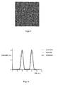
- Fig. 2
- die berechneten Intensitäten für eine destruktive und eine konstruktive Interferenz und für eine inkohärente Überlagerung dieser Objektpunkte,
- Fig. 3
- eine Simulation der Rekonstruktion einer flächigen Szene aus mit Zufallsphasen berechneten Objektpunkten mit einem Objektpunktabstand gemäß
Fig. 1 und 2 , - Fig. 4
- die analogen Überlagerungen für einen vierfach größeren Abstand zwischen den zwei Objektpunkten aus
Fig. 2 , - Fig. 5
- eine Simulation der Rekonstruktion einer flächigen Szene aus mit Zufallsphasen berechneten Objektpunkten mit einem Objektpunktabstand gemäß
Fig. 4 , - Fig. 6
- eine Simulation einer Rekonstruktion, bei der 16 Einzelrekonstruktionen erzeugt und inkohärent überlagert wurden, und
- Fig. 7
- eine schematische Darstellung der Hauptkomponenten eines holographischen Displays gemäß der Erfindung.
- Fig. 1
- the course of the amplitude of the Airy function for two object points that are no longer resolved separately,
- Fig. 2
- the calculated intensities for a destructive and a constructive interference and for an incoherent superposition of these object points,
- Fig. 3
- a simulation of the reconstruction of a planar scene of random points calculated object points with an object point distance according to
Fig. 1 and 2 . - Fig. 4
- the analog overlays for a four times greater distance between the two object points
Fig. 2 . - Fig. 5
- a simulation of the reconstruction of a planar scene of random points calculated object points with an object point distance according to
Fig. 4 . - Fig. 6
- a simulation of a reconstruction in which 16 individual reconstructions were generated and superimposed incoherently, and
- Fig. 7
- a schematic representation of the main components of a holographic display according to the invention.
Die erfindungsgemäße holographische Rekonstruktionseinrichtung umfasst wenigstens ein Lichtmodulationsmittel, ein Rekonstruktionsmittel und ein Lichtquellenmittel, die ein- oder mehrteilig ausgebildet sein können. Weiterhin sind Systemsteuermittel vorgesehen, die mehrere Speichermittel und Recheneinheiten aufweisen, um die programmtechnischen Berechnungen und Abläufe in der holographischen Rekonstruktionseinrichtung auszuführen und zu koordinieren.The holographic reconstruction device according to the invention comprises at least one light modulation means, a reconstruction means and a light source means, which may be formed in one or more parts. Furthermore, system control means are provided, which have a plurality of storage means and arithmetic units, in order to execute and coordinate the program-specific calculations and sequences in the holographic reconstruction device.
Die Erfindung wird im Verfahrensablauf hauptsächlich an zwei Objektpunkten, die stellvertretend für die gesamte Szene dienen, beschrieben.The invention will be described in the process mainly at two object points that serve as a representative of the entire scene described.
Wie eingangs angeführt, werden durch die Beugung des kohärenten Lichts des Lichtquellenmittels störende Interferenzmaxima und Interferenzminima zwischen einzelnen Objektpunkten einer Szene hervorgerufen. Diese sieht ein Betrachter als eine störende granulare Struktur, die als Specklemuster bezeichnet wird.As mentioned above, disturbing interference maxima and interference minima between individual object points of a scene are caused by the diffraction of the coherent light of the light source means. This sees a viewer as a disruptive granular structure called the bacon pattern.
Die Erfindung beseitigt die Specklemuster dadurch, dass die Auflösung der Rekonstruktion der Szene an die für das Auge sichtbare Auflösung oder an die Abbildungseigenschaften des Rekonstruktionsmittels oder an die Auflösung des Lichtmodulationsmittels angepasst wird. Dafür müssen die Objektpunkte der Szene zwei verschiedenen Kriterien genügen, auf die in den Ausgestaltungsbeispielen näher eingegangen wird.The invention eliminates the speckle patterns by adjusting the resolution of the reconstruction of the scene to the resolution visible to the eye or to the imaging properties of the reconstruction means or to the resolution of the light modulation means. For this purpose, the object points of the scene must satisfy two different criteria, which are discussed in more detail in the exemplary embodiments.
Ein Betrachter sieht eine Rekonstruktion mit seiner Augenpupille. Dabei wirkt die Pupille als beugungsbegrenzende Öffnung.A viewer sees a reconstruction with his eye pupil. The pupil acts as a diffraction-limiting opening.
Bei einer kreisförmigen Öffnung wie der Augenpupille wird das Auflösungsvermögen des Auges und damit der Verlauf der Amplituden von Objektpunkten allgemein durch die Airy Funktion ![]()
![]()
Dabei sind r0 = (x0, y0) die Koordinate eines Objektpunktes und r-r0 der Abstand von dieser Koordinate innerhalb einer Schnittebene der Szene, und j1 ist eine Besselfunktion.Where r0 = (x0, y0) is the coordinate of an object point and r-r0 is the distance from that coordinate within a slice plane of the scene, and j1 is a Bessel function.
Sofern durch das Rekonstruktionsmittel keine anderen begrenzenden Faktoren gegeben sind, sieht der Betrachter einen Objektpunkt als ein Beugungsscheibchen. Dieses Beugungsscheibchen hat den Durchmesser Bd = 1,22 lambda D / dp.Unless otherwise limited by the reconstruction means, the observer sees an object point as a diffraction disk. This diffraction disk has the diameter Bd = 1.22 lambda D / dp.
Dabei sind mit D der Abstand zwischen der Ebene der aktuellen Augenposition und der jeweiligen Schnittebene, mit lambda die Wellenlänge des Lichtes und mit dp der Durchmesser der Augenpupille bezeichnet.In this case, D denotes the distance between the plane of the current eye position and the respective sectional plane, lambda the wavelength of the light and dp the diameter of the eye pupil.
Zwei Objektpunkte an den Orten r0a und r0b können noch als getrennt aufgelöst wahrgenommen werden, wenn ihr Abstand zueinander r0b-r0a >= 1,22 lambda D /dp ist. Dann fällt das Maximum der Funktion J1(r-r0a) / (r-r0a) für den einen Objektpunkt mit dem ersten Minimum der Funktion J2 (r-r0b) / (r-r0b) für den anderen Objektpunkt zusammen.Two object points at the locations r0a and r0b can still be perceived as separated when their distance from each other r0b-r0a> = 1.22 lambda D / dp. Then the maximum of the function J1 (r-r0a) / (r-r0a) for the one object point coincides with the first minimum of the function J2 (r-r0b) / (r-r0b) for the other object point.
In
Liegen die Beugungsscheibchen zweier Objektpunkte dicht beieinander und überlappen sich, so beeinflussen die relativen Phasen beider Objektpunkte maßgeblich die resultierende kohärente Rekonstruktion dieser Objektpunkte. Es können daher für eine konstruktive Interferenz deutliche Intensitätsmaxima oder für eine destruktive Interferenz deutliche Intensitätsminima entstehen.If the diffraction disks of two object points lie close together and overlap, the relative phases of both object points significantly influence the resulting coherent reconstruction of these object points. It is therefore possible for constructive interference to produce distinct intensity maxima or significant intensity minima for destructive interference.
In
Die Intensität für den allgemeinen Fall einer kohärenten Überlagerung - abhängig von der relativen Phase beider Objektpunkte - liegt zwischen den Extremfällen der destruktiven und konstruktiven Interferenz. Die Interferenz bei der kohärenten Überlagerung mehrerer Objektpunkte würde dagegen ein Specklemuster hervorrufen.The intensity for the general case of a coherent superposition - depending on the relative phase of both object points - lies between the extreme cases of destructive and constructive interference. The interference in the coherent superposition of several object points, however, would cause a speckle pattern.
Der Betrachter sieht die Rekonstruktion der Szene entsprechend
Maßgeblich für die Art der auftretenden Interferenz ist der optische Wegunterschied des Lichtes von verschiedenen Objektpunkten OP zum Betrachterfenster VW.Decisive for the type of interference occurring is the optical path difference of the light from different object points OP to the viewer window VW.
Für verschiedene Positionen der Augenpupille innerhalb des Betrachterfensters VW unterscheidet sich aber dieser optische Wegunterschied. Daher können für eine Augenbewegung innerhalb des Betrachterfensters VW unterschiedliche Interferenzen auftreten. Im Extremfall ist ein Wechsel von konstruktiver nach destruktiver Interferenz oder umgekehrt möglich.For different positions of the eye pupil within the observer window VW but differs this optical path difference. Therefore, for eye movement within the viewer window VW different interference may occur. In extreme cases, a change from constructive to destructive interference or vice versa is possible.
Damit ein Betrachter aus allen Augenpositionen AP innerhalb des Betrachterfensters VW eine Rekonstruktion in guter Qualität sieht, ist es notwendig, geringe Unterschiede zwischen konstruktiver und destruktiver Interferenz zu haben.In order for a viewer to see a reconstruction of good quality from all eye positions AP within the observer window VW, it is necessary to have small differences between constructive and destructive interference.
In
Dieses Specklemuster kommt durch die Interferenz der beiden Objektpunkte zustande. Würde sich der Betrachter im Betrachterfenster bewegen, würde sich das Specklemuster verändern.This speckle pattern is due to the interference of the two object points. If the viewer moved in the viewer window, the speckle pattern would change.
Um eine gleichmäßig hell leuchtende Fläche ohne die störenden Specklemuster zu realisieren, muss daher die sichtbare Auflösung der Rekonstruktion der Szene entweder an das Auflösungsvermögen des Auges oder z.B. an das Auflösungsvermögen bzw. die Abbildungseigenschaften des Rekonstruktionsmittels angepasst werden.Therefore, to realize a uniformly bright surface without the disturbing speckle patterns, the visible resolution of the reconstruction of the scene must be adjusted either to the resolution of the eye or e.g. be adapted to the resolution or the imaging properties of the reconstruction means.
Liegen die Beugungsscheibchen verschiedener Objektpunkte weit voneinander entfernt, so interferieren nur die kleinen Nebenmaxima. Es ergeben sich daher nur geringe Unterschiede zwischen der destruktiven und der konstruktiven Interferenz oder der inkohärenten Überlagerung der Beugungsscheibchen der Objektpunkte.If the diffraction disks of different object points are far apart, only the small secondary maxima interfere. It therefore only arise small differences between the destructive and the constructive interference or the incoherent superposition of the diffraction disks of the object points.
Eine bessere Reduzierung der Specklemuster erhält man, wenn zwei benachbarte Objektpunkte für die Zusammenstellung in einer Objektpunktgruppe ausgewählt werden, die weit genug auseinander liegen.A better reduction of the speckle patterns is obtained when two adjacent object points are selected for composition in an object point group that are far enough apart.
Dementsprechend ist in
Die Werte der Intensitäten für die konstruktive und destruktive Interferenz und auch der Wert der inkohärenten Überlagerung beider Objektpunkte unterscheiden sich hier nur sehr wenig voneinander. Die zwei Objektpunkte sind dadurch in der Rekonstruktion deutlich getrennt zu sehen.The values of the intensities for the constructive and destructive interference and also the value of the incoherent superposition of both object points differ only slightly from each other. The two object points are thus clearly separated in the reconstruction.
Die
Mit einem einzelnen Hologramm gemäß
Für die Verschiebung wird zunächst eine zweidimensionale Anordnung von Objektpunkten mit einem Abstand 1,0 lambda D / dp wie in
Die Darstellung in
Das in
Die schematische Darstellung in
Nachfolgend wird die Erfindung anhand von Ausgestaltungsbeispielen näher beschrieben.The invention will be described in more detail below with reference to exemplary embodiments.
In einer ersten Ausgestaltung der Erfindung wird dargelegt, wie die sichtbare Auflösung der Rekonstruktion einer Szene an die sichtbare Auflösung des Auges eines Betrachters angepasst wird.In a first embodiment of the invention, it is explained how the visible resolution of the reconstruction of a scene is adapted to the visible resolution of the eye of a viewer.
Zunächst generieren die Systemsteuermittel in einem ersten Verfahrensschritt ein Raster aus Schnittpunkten horizontaler und vertikaler Linien in einer Schnittebene der Szene. Hierzu wird von einer aktuellen Augenposition eines Betrachters ausgegangen. Für diese ist entweder ein Abstand zu den Schnittebenen fest vorgegeben, dann muss sich der Betrachter an einer festen Position aufhalten. Oder der Abstand wird von einem Positionsfinder ermittelt.First, in a first method step, the system control means generate a grid of intersection points of horizontal and vertical lines in a sectional plane the scene. For this purpose, a current eye position of a viewer is assumed. For these either a distance to the cutting planes is fixed, then the viewer must be in a fixed position. Or the distance is determined by a position finder.
Weiterhin wird die Pupillengröße des Betrachters zum Durchführen der Berechnungen benötigt. Dazu wird im Verfahren entweder von einem typischen Durchmesser der Augenpupille ausgegangen, oder der Durchmesser der aktuellen Augenpupille wird ebenfalls vom Positionsfinder oder einem vorgesehenen Sensor ermittelt und in Speichermitteln gespeichert.Furthermore, the pupil size of the observer is needed to perform the calculations. For this purpose, in the method either a typical diameter of the eye pupil is assumed, or the diameter of the current eye pupil is also determined by the position finder or an intended sensor and stored in memory means.
Eine andere mögliche Einrichtung zum Ermitteln der aktuellen Größe der Augenpupille ist so ausgebildet, dass ein Sensor den aktuellen Helligkeitswert der zu rekonstruierenden Szene oder des Umgebungslichts in einem Rekonstruktionsraum erfasst und den Recheneinheiten zuführt, die daraus die Pupillengröße berechnen. Anschließend werden an diesen Wert durch die Systemsteuermittel das Rastermass für die jeweilige Schnittebene und der Mindestabstand der Objektpunkte für die Berechnung der einzelnen CGH angepasst.Another possible device for determining the current size of the eye pupil is designed such that a sensor detects the current brightness value of the scene to be reconstructed or the ambient light in a reconstruction space and supplies it to the arithmetic units which calculate the pupil size therefrom. Subsequently, the grid dimension for the respective sectional plane and the minimum distance of the object points for the calculation of the individual CGH are adapted to this value by the system control means.
Die Recheneinheiten als Bestandteil der Systemsteuermittel berechnen mit dem Abstand der Augenposition von jeweils einer Schnittebene der Szene und dem Pupillendurchmesser eine Objektpunktdichte, die dichter als das Auflösungsvermögen des Auges ist. Anhand der Objektpunktdichte bestimmt das Systemsteuermittel das Rastermass für benachbarte Objektpunkte in der jeweiligen Schnittebene. Die Linien des Rasters verlaufen in jeder Richtung parallel zueinander und weisen untereinander das gleiche Rastermass auf. Durch den unterschiedlichen Abstand der einzelnen Schnittebenen zur Augenposition des jeweiligen Betrachters unterscheiden sich die Rastermasse der einzelnen Schnittebenen.The computing units as part of the system control means calculate with the distance of the eye position of each of a sectional plane of the scene and the pupil diameter an object point density which is denser than the resolution of the eye. On the basis of the object point density, the system control means determines the grid size for adjacent object points in the respective sectional plane. The lines of the grid run parallel to each other in each direction and have the same grid size among each other. Due to the different spacing of the individual cutting planes to the eye position of the respective viewer, the grid dimensions of the individual cutting planes differ.
Objektpunkte in benachbarten Rasterpositionen einer Schnittebene weisen horizontal und vertikal einen lateralen Abstand zueinander auf, durch den sie, bezogen auf einen definierten axialen Abstand des Auges zu dieser Schnittebene, nicht mehr getrennt auflösbar sind. Mehrere benachbarte Punkte werden dann als zusammenhängende Fläche wahrgenommen. Damit wird das erste Kriterium der Erfindung, bezogen auf die Objektpunktdichte, erfüllt.Object points in adjacent raster positions of a sectional plane have horizontally and vertically a lateral distance from one another, by means of which they can no longer be resolved separately relative to a defined axial distance of the eye from this sectional plane. Several adjacent points are then perceived as a contiguous area. Thus, the first criterion of the invention, based on the object point density, met.
Die für einen zu rekonstruierenden Objektpunkt charakteristischen Daten werden in Speichermitteln der Systemsteuermittel in einem Datensatz gespeichert und sind dort programmtechnisch abrufbar.The data characteristic of an object point to be reconstructed are stored in storage means of the system control means in a data record and can be retrieved there programmatically.
In einem zweiten Verfahrensschritt muss die Objektpunktdichte entsprechend dem Zweiten Kriterium der Erfindung reduziert werden, um in der Rekonstruktion die Objektpunkte wieder deutlich getrennt sehen zu können. Deshalb werden solche Objektpunkte einer Schnittebene zu Objektpunktgruppen zusammengestellt, die anhand der gespeicherten Daten einen Abstand zueinander aufweisen, mit dem sie für einen Betrachter in definiertem axialen Abstand zu dieser Schnittebene getrennt aufgelöst gesehen werden.In a second method step, the object point density must be reduced in accordance with the second criterion of the invention in order to be able to clearly see the object points clearly separated in the reconstruction. Therefore, such object points of a sectional plane are combined into object point groups, which have a distance from one another on the basis of the stored data, with which they are seen separately resolved for a viewer at a defined axial distance to this sectional plane.
In der erfindungsgemäßen Einrichtung wird in weiteren Verfahrensschritten aus jeder Objektpunktgruppe ein computergeneriertes Hologramm (CGH) berechnet und in ein Lichtmodulationsmittel kodiert, auf das kohärentes Licht eines Lichtquellenmittels fällt. Zur Modulation der Wellenfronten des einfallenden kohärenten Lichts weist das Lichtmodulationsmittel steuerbare Elemente, z.B. regulär angeordnete Pixel auf.In the device according to the invention, in further method steps, a computer-generated hologram (CGH) is calculated from each object point group and coded into a light modulation means onto which coherent light of a light source means falls. To modulate the wavefronts of the incident coherent light, the light modulation means comprises controllable elements, e.g. regularly arranged pixels.
Für eine eindimensionale Kodierung werden beispielsweise 2, 3 oder 4 Objektpunktgruppen, für eine zweidimensionale Kodierung 4, 9, oder 16 Objektpunktgruppen zusammengestellt und als Hologramme berechnet. Entsprechend groß ist die Anzahl der jeweils zu erzeugenden einzelnen Rekonstruktionen.For a one-dimensional coding, for example, 2, 3 or 4 object point groups, for a two-dimensional coding 4, 9, or 16 object point groups are compiled and calculated as holograms. The number of individual reconstructions to be generated is correspondingly large.
Ein Rekonstruktionsmittel der holographischen Einrichtung erzeugt von jeder Objektpunktgruppe eine einzelne Rekonstruktion. Die Systemsteuermittel überlagern die Rekonstruktionen inkohärent, wodurch eine einzige holographische Rekonstruktion der Szene in der Ebene der aktuellen Augenposition eines Betrachters zu sehen ist.A reconstruction means of the holographic device generates a single reconstruction of each object point group. The system control means overlays the reconstructions incoherently, whereby a single holographic reconstruction of the scene is seen in the plane of the current eye position of a viewer.
Die inkohärente Überlagerung der einzelnen Rekonstruktionen in der Augenposition kann einerseits zeitsequentiell durchgeführt werden. Dazu werden die einzelnen Rekonstruktionen inkohärent zeitlich so schnell überlagert, dass die Augen des Betrachters zeitlich die Intensität der Rekonstruktion über die Summe der Intensitäten der einzelnen Rekonstruktionen mitteln.The incoherent superimposition of the individual reconstructions in the eye position can on the one hand be performed time sequentially. For this purpose, the individual reconstructions are overlaid incoherently in time so quickly that the eyes of the Averaging the intensity of the reconstruction over the sum of the intensities of the individual reconstructions.
Andererseits kann die inkohärente Überlagerung der einzelnen Rekonstruktionen gleichzeitig durchgeführt werden, indem mit mehreren Lichtmodulatoren und mehreren Rekonstruktionsmitteln gleichzeitig mehrere einzelne Rekonstruktionen erzeugt und inkohärent am Ort der Augenposition überlagert werden.On the other hand, the incoherent superimposition of the individual reconstructions can be carried out at the same time by simultaneously generating a plurality of individual reconstructions with a plurality of light modulators and a plurality of reconstruction means and superimposing them incoherently at the location of the eye position.
Objektpunkte der Szene, die die zwei angeführten Kriterien erfüllen, weisen bei ihrer Rekonstruktion nur geringe oder keine Specklemuster auf. In beiden Fällen sieht ein Betrachter von der aktuellen Augenposition aus die Rekonstruktion der gesamten Szene gemittelt nur mit geringem Specklemuster.Object points of the scene that meet the two listed criteria have little or no speckle patterns in their reconstruction. In both cases, a viewer sees from the current eye position, the reconstruction of the entire scene averaged only with low speckle pattern.
In einer zweiten Ausgestaltung der Erfindung wird die sichtbare Auflösung der Rekonstruktion der Szene an die sichtbare Auflösung eines Rekonstruktionsmittels angepasst. Das bedeutet, dass anstelle der Wirkung der Augenpupille die Wirkung der Pupille der Rekonstruktionsoptik bzw. dessen Abbildungsqualität tritt, wobei die Rekonstruktionsoptik ein Bestandteil des Rekonstruktionsmittels ist.In a second embodiment of the invention, the visible resolution of the reconstruction of the scene is adapted to the visible resolution of a reconstruction means. This means that instead of the effect of the eye pupil, the effect of the pupil of the reconstruction optics or its imaging quality occurs, wherein the reconstruction optics is a component of the reconstruction means.
Es kann z.B. auch durch die räumliche Ausdehnung der Lichtquelle oder durch eine nichtideale Wiedergabe der eingeschriebenen Werte auf dem SLM oder durch Aberrationen in der Rekonstruktionsoptik ein einzelner Objektpunkt verbreitert rekonstruiert werden. Die sichtbare Auflösung des Objektpunktes ist dann beugungsbegrenzt nicht durch die Augenpupille gegeben. In diesem Fall ist die Ausgangs-Objektpunktdichte so zu wählen, dass die von der gesamten Einrichtung zur Rekonstruktion tatsächlich rekonstruierten Objektpunkte gerade nicht mehr getrennt, sondern noch als zusammenhängende Fläche wahrgenommen werden.It can e.g. also be reconstructed by the spatial extent of the light source or by a non-ideal representation of the written values on the SLM or by aberrations in the reconstruction optics widened a single object point. The visible resolution of the object point is then diffraction-limited not given by the eye pupil. In this case, the initial object point density should be chosen such that the object points actually reconstructed by the entire reconstruction device are no longer separated, but are still perceived as a contiguous surface.
Dazu wird in einem Verfahrensschritt mindestens eine Messkurve für die Rekonstruktion eines einzelnen Objektpunktes z.B. in verschiedenen Abständen vom SLM mit der vorgesehenen Rekonstruktionsoptik für die holographische Rekonstruktion aufgenommen und im Speichermittel gespeichert. Wahlweise kann auch ein aus der Messkurve berechneter Parameter, der den Objektpunkt charakterisiert, im Speichermittel gespeichert werden. Aus der Breite und dem Verlauf dieser Messkurve bestimmen die Systemsteuermittel die Objektpunktdichte und legen in Abhängigkeit von einer aktuellen Augenposition des Betrachters ein Raster für die Objektpunkte der Szene fest. Wie bereits in der ersten Ausgestaltung beschrieben, muss dann die Objektpunktdichte wieder reduziert werden.For this purpose, in one method step, at least one measurement curve for the reconstruction of a single object point, for example at different distances from the SLM, is recorded with the envisaged reconstruction optics for the holographic reconstruction and stored in the storage means. Alternatively, a parameter calculated from the measurement curve, which characterizes the object point, can also be stored in the storage means. From the width and the course of this measurement curve, the system control means determine the density of object points and insert in dependence on a current eye position of the observer Grid for the object points of the scene. As already described in the first embodiment, then the object point density must be reduced again.
Dazu werden Objektpunkte mit einem definierten Abstand zueinander ausgewählt und derart zu Objektpunktgruppen zusammengestellt, dass sie einzeln aufgelöst erkennbar sind.For this purpose, object points are selected with a defined distance from one another and assembled in such a way to object point groups that they are individually resolved recognizable.
Die Kodierung im Lichtmodulationsmittel und die Rekonstruktion der einzelnen Objektpunktgruppen erfolgen analog den in der ersten Ausgestaltung der Erfindung beschriebenen Verfahrensabläufen unter Berücksichtigung der Abbildungsqualität des Rekonstruktionsmittels.The coding in the light modulation means and the reconstruction of the individual object point groups are carried out analogously to the process sequences described in the first embodiment of the invention, taking into account the imaging quality of the reconstruction means.
In einer Variante dieser Ausgestaltung tritt anstelle einer Messkurve für die Rekonstruktion eines Objektpunktes in verschiedenen Abständen vom SLM die Simulation der Eigenschaften der Einrichtung zur Rekonstruktion.In a variant of this embodiment, instead of a measurement curve for the reconstruction of an object point at different distances from the SLM, the simulation of the properties of the device for reconstruction occurs.
Entsprechend einer dritten Ausgestaltung der Erfindung kann die sichtbare Auflösung der Rekonstruktion der Szene an das Auflösungsvermögen des Lichtmodulationsmittels angepasst werden. Die Rekonstruktion der Szene ist von der Augenposition aus im Betrachterfenster sichtbar. Die Größe des Betrachterfensters ist abhängig vom Auflösungsvermögen des Lichtmodulationsmittels als ![]()
wobei D der Abstand des Betrachterauges zum Lichtmodulationsmittel, lambda die Wellenlänge und p_h, v der Pixelpitch zwischen zwei Pixeln in horizontaler (h) oder vertikaler (v) Richtung sind. Dabei sind die zwei Pixel steuerbare Elemente des Lichtmodulationsmittels, in die eine komplexwertige Zahl kodiert ist.According to a third embodiment of the invention, the visible resolution of the reconstruction of the scene can be adapted to the resolution of the light modulation means. The reconstruction of the scene is visible from the eye position in the viewer window. The size of the observer window depends on the resolution of the light modulation means as ![]()
where D is the distance of the observer eye to the light modulation means, lambda the wavelength and p_h, v the pixel pitch between two pixels in the horizontal (h) or vertical (v) direction. In this case, the two pixels are controllable elements of the light modulation means, in which a complex-valued number is encoded.
Das Betrachterfenster hat im Allgemeinen eine rechteckige Form.The viewer window is generally rectangular in shape.
Ist das Betrachterfenster in einer oder beiden Dimensionen h und/ oder v kleiner als der Durchmesser der Augenpupille dp, so wird die wahrnehmbare Auflösung der Szene durch die Ausdehnung des Betrachterfensters bestimmt und nicht durch die sichtbare Auflösung der Augenpupille.If the observer window is smaller than the diameter of the eye pupil dp in one or both of the dimensions h and / or v, the perceptible resolution of the scene is determined by the extent of the observer window and not by the visible resolution of the eye pupil.
Ist das Betrachterfenster in beiden Dimensionen kleiner als der Durchmesser der Augenpupille, so tritt z.B. an die Stelle der Airy Funktion das Produkt zweier sinc-Funktionen ![]()
![]()
Die erfindungsgemäße Einrichtung und das entsprechende Verfahren sind dann analog auf diese Auflösung zu modifizieren.The device according to the invention and the corresponding method are then to be modified analogously to this resolution.
In einem vierten Ausgestaltungsbeispiel der Erfindung sind eine Einrichtung und ein Verfahren zum holographischen Rekonstruieren einer farbigen Szene vorgesehen. Hier erfolgt die Zerlegung der farbigen Szene programmtechnisch in den Systemsteuermitteln in unterschiedliche Anteile der vorgesehenen Farben. Die farbige Rekonstruktion der Szene wird aus mindestens zwei unterschiedlichen einfarbigen Rekonstruktionen verschiedener Wellenlängen des Lichts erzeugt. Für jeden Farbanteil wird jeweils eine Zerlegung der Szene in Objektpunkte, eine Zusammenstellung der Objektpunkte zu Objektpunktgruppen und eine Berechnung und Kodierung der einfarbigen CGH separat analog der Beschreibung zur ersten Ausgestaltung der Erfindung vorgenommen.In a fourth embodiment of the invention, a device and a method for holographic reconstruction of a colored scene are provided. Here, the decomposition of the colored scene is done programmatically in the system control means in different proportions of the colors provided. The color reconstruction of the scene is generated from at least two different monochrome reconstructions of different wavelengths of light. For each color component, a decomposition of the scene into object points, a compilation of the object points to object point groups, and a calculation and encoding of the monochrome CGH are carried out separately analogously to the description of the first embodiment of the invention.
In den Datensätzen der Objektpunkte werden von den Recheneinheiten zum Durchführen des Rekonstruktionsverfahrens für jede Wellenlänge der verwendeten Grundfarben für das Raster unterschiedliche Rastermaße und für die Objektpunktgruppen unterschiedliche Mindestabstände vorgegeben. In Abwandlung dieses Verfahrensschrittes können zum Vereinfachen der Berechnungen und Verfahrensabläufe in den Datensätzen der Objektpunkte für jede Wellenlänge der drei Grundfarben für das Raster gleiche Rastermaße und für die Objektpunktgruppen gleiche Mindestabstände durch die Recheneinheiten vorgegeben werden.In the data sets of the object points, the arithmetic units for carrying out the reconstruction method specify different grid dimensions for each wavelength of the primary colors used for the grid, and different minimum distances for the object point groups. In a modification of this method step, for simplifying the calculations and procedures in the data sets of the object points for each wavelength of the three primary colors for the grid the same grid dimensions and for the object point groups equal minimum distances can be specified by the arithmetic units.
Dabei wird als erstes Kriterium vorteilhaft das Rastermaß für die Objektpunkte der Szene in den Recheneinheiten so klein definiert, dass für die Wellenlängen der verwendeten Grundfarben die Objektpunkte nicht mehr getrennt aufgelöst werden können. Das zweite Kriterium des Verfahrens wird dadurch realisiert, dass der Abstand der Objektpunkte innerhalb einer Objektpunktgruppe in den Recheneinheiten so groß definiert wird, dass für die Wellenlängen der drei Grundfarben die Objektpunkte getrennt aufgelöst werden können.In this case, as the first criterion, the grid dimension for the object points of the scene in the arithmetic units is advantageously defined so small that the object points can no longer be resolved separately for the wavelengths of the primary colors used. The second criterion of the method is realized in that the distance between the object points within an object point group in the arithmetic units is defined so large that the object points can be resolved separately for the wavelengths of the three primary colors.
Mit der Anpassung der Auflösung der Rekonstruktion der farbigen Szene an z.B. die sichtbare Auflösung des Auges wird die Aufgabe gelöst, ein Reduzieren von Specklemustern der Rekonstruktion der Szene zu erreichen.By adapting the resolution of the reconstruction of the colored scene to, for example, the visible resolution of the eye, the problem of achieving a reduction of bacon patterns in the reconstruction of the scene is solved.
Eine erfindungsgemäße holographische Rekonstruktionseinrichtung kann als transmissives oder reflektives holographisches Display ausgebildet sein und sowohl für einen Betrachter als auch für mehrere Betrachter konzipiert werden.A holographic reconstruction device according to the invention can be designed as a transmissive or reflective holographic display and can be designed both for a viewer and for several observers.
Claims (13)
- Method for holographically reconstructing a scene,
where the scene is divided by parallel section layers into object points by software means, where the object points are selected in accordance with a defined grid in the section layers and combined to form object point groups by system controller means, where a computer-generated hologram (CGH) is computed of each object point group and encoded on a light modulator means which is illuminated by coherent light that is emitted by a light source means,
where a reconstruction means generates a reconstruction from each CGH of an object point group and superposes the generated reconstructions incoherently by adding up the individual CGHs, so that a single holographic reconstruction of the scene becomes visible in the plane of the eye position of an observer, and
where the system controller means are provided with storage means for storing data records of the object points, characterised in that
the system controller means perform both the selection of object points in the section layers according to the grid and the combination of object points to form object point groups in dependence on the visible resolution of the reconstruction of the scene, where the system controller means- Generate the section layers at different distances from the eye position and define in each section layer a grid in which adjacent object points are situated so close to each other that their mutual distance is smaller than the visible resolution of the reconstruction of the scene for that section layer, and- Combine those object points of the respective section layer whose mutual distance is larger than the visible resolution of the reconstruction of the scene to for an object point group, and compute the CGH of the object point group from the data records which comprise the lateral distances between the object points of that group which are characterising of the visible resolution and the complex values of the object points. - Method according to claim 1, where computing units in the system controller means compute based on the distance of the actual eye position to the respective section layer of the scene and on the actual eye pupil diameter of an observer an object point density for determining the pitch of the object points in the section layers.
- Method according to claim 1, where the incoherent superposition of the individual reconstructions is carried out sequentially, so that the eyes of the observer temporally average out the intensity of the reconstruction over the sum of the intensities of the individual reconstructions, or where the incoherent superposition of the individual reconstructions is performed simultaneously, in that multiple light modulators and multiple reconstruction means generate multiple reconstructions at the same time and superpose them incoherently at the position of the observer eye.
- Method according to claim 1, where the visible resolution of the reconstruction of the scene is adapted to the resolution of the light modulator means.
- Method according to claim 1 for holographically reconstructing a colour scene, where the colour scene is divided into different colour components by software means in the system controller means, and where the colour reconstruction is composed of at least two different monochromic reconstructions of different wavelengths of the light, where a division of the scene into object points, a combination of the object points to form object point groups, and a computation of the monochromic CGHs is performed separately for each colour component.
- Method according to claim 5, where different grid pitches are defined for each wavelength of the three primary colours, and different minimum distances are defined for the object point groups by the computing units in the data records of the object points, or where same grid pitches are defined for each wavelength of the three primary colours, and same minimum distances are defined for the object point groups by the computing units in the data records of the object points.
- Method according to claim 6, where the pitch of the object points of the scene is defined by the computing units to be so small that for the wavelengths of the three primary colours the object points can no longer be resolved as separate points, or where the distance of the object points within an object point group is defined by the computing units to be so large that for the wavelengths of the three primary colours the object points can be resolved as separate points.
- Method according to claim 1 or 5, where each object point of the divided scene is selected only once for one of the object point groups.
- Method according to claim 1, where the visible resolution of the reconstruction of the scene is adapted to the imaging properties of the reconstruction means, and where the imaging properties of the reconstruction means optionally are found either by way of a simulation or based on a measured curve.
- Method according to claim 1, where the object point groups are encoded on the light modulator means either one-dimensionally or two-dimensionally.
- Device for holographically reconstructing a scene comprising a light modulator means which is illuminated with light emitted by a light source means and on which computer-generated holograms (CGHs) of object point groups of the scene are encoded,
a reconstruction means which generates a reconstruction from each CGH of an object point group and superposes the generated reconstructions incoherently by adding up the individual CGHs, so that a single holographic reconstruction of the scene becomes visible in the plane of the eye position of an observer, and
system controller means for dividing the scene by section layers into object points which are selected in accordance with a defined grid in the section layers and combined to form object point groups, said system controller means comprising storage means for storing data records of the object points, characterised in that
the system controller means are further designed- To generate the section layers at different distances from the eye position always with a grid in which adjacent object points are situated so close to each other that their mutual distance is smaller than the visible resolution of the reconstruction of the scene for the respective section layer, and- To combine those object points of the respective section layer whose mutual distance is larger than the visible resolution of the reconstruction of the scene to for an object point group, and to compute the CGH of each object point group from the data records which comprise the lateral distances between the object points of that group which are characterising of the visible resolution and the complex values of the object points. - Device according to claim 11, comprising a position finder for detecting the information about the actual eye position of at least one observer and about the actual size of the eye pupil of that observer.
- Device according to claim 12, where the position finder comprises a sensor for detecting an actual brightness value of the scene to be reconstructed or of the ambient light in a reconstruction space, where the brightness value serves to determine the actual diameter of the eye pupil.
Applications Claiming Priority (2)
| Application Number | Priority Date | Filing Date | Title |
|---|---|---|---|
| DE102007036127A DE102007036127A1 (en) | 2007-07-27 | 2007-07-27 | Holographic reconstruction device |
| PCT/EP2008/059765 WO2009016105A2 (en) | 2007-07-27 | 2008-07-25 | Holographic reconstruction device |
Publications (2)
| Publication Number | Publication Date |
|---|---|
| EP2181361A2 EP2181361A2 (en) | 2010-05-05 |
| EP2181361B1 true EP2181361B1 (en) | 2011-02-23 |
Family
ID=40157419
Family Applications (1)
| Application Number | Title | Priority Date | Filing Date |
|---|---|---|---|
| EP08786426A Active EP2181361B1 (en) | 2007-07-27 | 2008-07-25 | Holographic reconstruction device |
Country Status (10)
| Country | Link |
|---|---|
| US (1) | US8441703B2 (en) |
| EP (1) | EP2181361B1 (en) |
| JP (1) | JP5530927B2 (en) |
| KR (1) | KR101511397B1 (en) |
| CN (1) | CN101809511B (en) |
| AT (1) | ATE499635T1 (en) |
| CA (1) | CA2694525A1 (en) |
| DE (2) | DE102007036127A1 (en) |
| TW (1) | TWI431443B (en) |
| WO (1) | WO2009016105A2 (en) |
Families Citing this family (9)
| Publication number | Priority date | Publication date | Assignee | Title |
|---|---|---|---|---|
| EP2880496B1 (en) | 2012-08-01 | 2019-09-11 | Real View Imaging Ltd. | Increasing an area from which reconstruction from a computer generated hologram may be viewed |
| KR20150086799A (en) | 2014-01-20 | 2015-07-29 | 한국전자통신연구원 | Holographic display apparatus and method using optical fiber array backlight for portable device |
| DE102015110502A1 (en) | 2014-07-04 | 2016-01-07 | Seereal Technologies S.A. | Projection apparatus and method for displaying a two-dimensional and / or three-dimensional scene or content |
| KR102441587B1 (en) | 2015-08-03 | 2022-09-07 | 삼성전자주식회사 | Method and apparatus for processing holographic image |
| KR102464362B1 (en) * | 2015-09-30 | 2022-11-07 | 삼성전자주식회사 | Method and apparatus for processing holographic image |
| WO2017114789A2 (en) * | 2015-12-28 | 2017-07-06 | Seereal Technologies S.A. | Display device and method for optimizing the image quality |
| KR102571080B1 (en) | 2016-02-12 | 2023-08-25 | 삼성전자주식회사 | Method and apparatus for processing holographic image |
| CN105700321B (en) * | 2016-04-18 | 2018-02-16 | 中国工程物理研究院激光聚变研究中心 | Distance Judgment method is rebuild in Jiao based on the digital hologram rebuild as intensity variance |
| CN106339979B (en) * | 2016-08-30 | 2019-12-10 | 四川大学 | hash function-based calculation holographic encryption method |
Family Cites Families (18)
| Publication number | Priority date | Publication date | Assignee | Title |
|---|---|---|---|---|
| EP0540759B1 (en) * | 1991-05-21 | 1997-09-10 | Seiko Epson Corporation | Optical device and optical machining system using the optical device |
| JPH06110371A (en) * | 1992-09-30 | 1994-04-22 | Fujitsu Ltd | Method and device for stereographic display |
| JPH10288939A (en) * | 1997-04-16 | 1998-10-27 | Nippon Telegr & Teleph Corp <Ntt> | Method and device for generating computer hologram by using depth buffer |
| JP3778326B2 (en) * | 1997-05-22 | 2006-05-24 | 日本電信電話株式会社 | Computer generated hologram display method, apparatus, and recording medium on which computer generated hologram display program is recorded |
| EP1008919A1 (en) * | 1998-12-09 | 2000-06-14 | Communauté Européenne (CE) | Computer assisted holographic method and apparatus for reproducing three-dimensional images |
| GB2363273A (en) * | 2000-06-09 | 2001-12-12 | Secr Defence | Computation time reduction for three dimensional displays |
| JP2004517354A (en) * | 2000-11-07 | 2004-06-10 | ホログラフイツク・イメージング・エル・エル・シー | Improved method of generating computer generated hologram |
| RU2363025C2 (en) | 2002-11-13 | 2009-07-27 | Сириал Текнолоджиз Гмбх | Video hologram and device for restoration of video holograms |
| DE102004063838A1 (en) * | 2004-12-23 | 2006-07-06 | Seereal Technologies Gmbh | Method and apparatus for calculating computer generated video holograms |
| DE102005023743B4 (en) | 2005-05-13 | 2016-09-29 | Seereal Technologies Gmbh | Projection apparatus and method for holographic reconstruction of scenes |
| DE502006001767D1 (en) | 2005-05-13 | 2008-11-20 | Seereal Technologies Gmbh | PROJECTION DEVICE AND METHOD FOR HOLOGRAPHIC RECONSTRUCTION OF SCENES |
| KR101367573B1 (en) * | 2005-12-22 | 2014-02-25 | 시리얼 테크놀로지즈 에스.에이. | Method for the compensation of an inhomogeneous brightness perception in holographically reconstructed scenes |
| GB0601481D0 (en) * | 2006-01-25 | 2006-03-08 | Light Blue Optics Ltd | Methods and apparatus for displaying images using holograms |
| DE102006062377B4 (en) * | 2006-12-19 | 2018-03-22 | Seereal Technologies S.A. | Method and holographic display device for reducing speckle |
| DE102006062376B4 (en) * | 2006-12-19 | 2018-03-22 | Seereal Technologies S.A. | Method and display device for reducing speckle |
| DE102007023738A1 (en) * | 2007-05-16 | 2009-01-08 | Seereal Technologies S.A. | Method and device for reconstructing a three-dimensional scene in a holographic display |
| DE102007045332B4 (en) * | 2007-09-17 | 2019-01-17 | Seereal Technologies S.A. | Holographic display for reconstructing a scene |
| US8437059B2 (en) * | 2010-01-21 | 2013-05-07 | Technion Research & Development Foundation Limited | Method for reconstructing a holographic projection |
-
2007
- 2007-07-27 DE DE102007036127A patent/DE102007036127A1/en not_active Withdrawn
-
2008
- 2008-07-25 CN CN200880100780XA patent/CN101809511B/en active Active
- 2008-07-25 EP EP08786426A patent/EP2181361B1/en active Active
- 2008-07-25 WO PCT/EP2008/059765 patent/WO2009016105A2/en active Application Filing
- 2008-07-25 US US12/670,886 patent/US8441703B2/en active Active
- 2008-07-25 DE DE502008002689T patent/DE502008002689D1/en active Active
- 2008-07-25 KR KR1020107004235A patent/KR101511397B1/en active IP Right Grant
- 2008-07-25 CA CA2694525A patent/CA2694525A1/en not_active Abandoned
- 2008-07-25 AT AT08786426T patent/ATE499635T1/en active
- 2008-07-25 JP JP2010517410A patent/JP5530927B2/en active Active
- 2008-07-29 TW TW097128720A patent/TWI431443B/en active
Also Published As
| Publication number | Publication date |
|---|---|
| CN101809511A (en) | 2010-08-18 |
| WO2009016105A2 (en) | 2009-02-05 |
| TW200925804A (en) | 2009-06-16 |
| EP2181361A2 (en) | 2010-05-05 |
| US20100188719A1 (en) | 2010-07-29 |
| ATE499635T1 (en) | 2011-03-15 |
| US8441703B2 (en) | 2013-05-14 |
| TWI431443B (en) | 2014-03-21 |
| WO2009016105A4 (en) | 2009-07-09 |
| CA2694525A1 (en) | 2009-02-05 |
| DE502008002689D1 (en) | 2011-04-07 |
| KR20100051686A (en) | 2010-05-17 |
| CN101809511B (en) | 2013-05-15 |
| JP2010534859A (en) | 2010-11-11 |
| DE102007036127A1 (en) | 2009-01-29 |
| KR101511397B1 (en) | 2015-04-10 |
| JP5530927B2 (en) | 2014-06-25 |
| WO2009016105A3 (en) | 2009-05-07 |
Similar Documents
| Publication | Publication Date | Title |
|---|---|---|
| EP2181361B1 (en) | Holographic reconstruction device | |
| DE102007045332B4 (en) | Holographic display for reconstructing a scene | |
| EP2138910B1 (en) | Device for reconstructing video holograms | |
| DE102004044111B4 (en) | Method and device for coding and reconstructing computer-generated video holograms | |
| DE102007023785B4 (en) | Analytical method for calculating video holograms in real time and holographic display device | |
| DE102006062377B4 (en) | Method and holographic display device for reducing speckle | |
| DE102006062376B4 (en) | Method and display device for reducing speckle | |
| DE102005023743B4 (en) | Projection apparatus and method for holographic reconstruction of scenes | |
| EP1880252B1 (en) | Projection device and method for holographic reconstruction of scenes | |
| DE102007023739B4 (en) | Method for rendering and generating color video holograms in real time and holographic display device | |
| DE102008002692B4 (en) | Display device for three-dimensional holographic or stereoscopic display of spatial objects and method for determining an apodization function for an apodisation mask | |
| DE102007013431B4 (en) | Method and apparatus for reconstructing a three-dimensional scene with corrected visibility | |
| DE102007023738A1 (en) | Method and device for reconstructing a three-dimensional scene in a holographic display | |
| WO2008025839A1 (en) | Method for generating video holograms in real time by means of subholograms | |
| DE102015205873A1 (en) | Method for calculating holograms for holographic reconstruction of two-dimensional and / or three-dimensional scenes | |
| WO2008025844A1 (en) | Method for generating computer-generated video holograms in real time by means of propagation | |
| DE112007003043B4 (en) | Holographic projection device and method for observing a reconstructed scene | |
| DE112016006094T5 (en) | Display device and method for optimizing image quality | |
| DE102007019277A1 (en) | Device for generating holographic reconstructions with light modulators | |
| WO2017125403A2 (en) | Method and device for encoding complex-value signals for the reconstruction of three-dimensional objects | |
| DE102008040581A1 (en) | Controllable light modulation device for use in e.g. direct vision or projection display device in vehicle, has cells arranged in raster such that light bundles are bent without or with small intensity of sources of images at viewer eyes | |
| DE102006004299A1 (en) | Computer generated video hologram sequence data compression method, involves underlying all viewable object points in object point of same defined phase value, so that unchanged points of object imply unchanged hologram values |
Legal Events
| Date | Code | Title | Description |
|---|---|---|---|
| PUAI | Public reference made under article 153(3) epc to a published international application that has entered the european phase |
Free format text: ORIGINAL CODE: 0009012 |
|
| 17P | Request for examination filed |
Effective date: 20100223 |
|
| AK | Designated contracting states |
Kind code of ref document: A2 Designated state(s): AT BE BG CH CY CZ DE DK EE ES FI FR GB GR HR HU IE IS IT LI LT LU LV MC MT NL NO PL PT RO SE SI SK TR |
|
| AX | Request for extension of the european patent |
Extension state: AL BA MK RS |
|
| GRAP | Despatch of communication of intention to grant a patent |
Free format text: ORIGINAL CODE: EPIDOSNIGR1 |
|
| DAX | Request for extension of the european patent (deleted) | ||
| GRAS | Grant fee paid |
Free format text: ORIGINAL CODE: EPIDOSNIGR3 |
|
| GRAA | (expected) grant |
Free format text: ORIGINAL CODE: 0009210 |
|
| AK | Designated contracting states |
Kind code of ref document: B1 Designated state(s): AT BE BG CH CY CZ DE DK EE ES FI FR GB GR HR HU IE IS IT LI LT LU LV MC MT NL NO PL PT RO SE SI SK TR |
|
| REG | Reference to a national code |
Ref country code: GB Ref legal event code: FG4D Free format text: NOT ENGLISH |
|
| REG | Reference to a national code |
Ref country code: CH Ref legal event code: EP |
|
| REG | Reference to a national code |
Ref country code: IE Ref legal event code: FG4D Free format text: LANGUAGE OF EP DOCUMENT: GERMAN |
|
| REF | Corresponds to: |
Ref document number: 502008002689 Country of ref document: DE Date of ref document: 20110407 Kind code of ref document: P |
|
| REG | Reference to a national code |
Ref country code: DE Ref legal event code: R096 Ref document number: 502008002689 Country of ref document: DE Effective date: 20110407 |
|
| REG | Reference to a national code |
Ref country code: NL Ref legal event code: VDEP Effective date: 20110223 |
|
| LTIE | Lt: invalidation of european patent or patent extension |
Effective date: 20110223 |
|
| PG25 | Lapsed in a contracting state [announced via postgrant information from national office to epo] |
Ref country code: LV Free format text: LAPSE BECAUSE OF FAILURE TO SUBMIT A TRANSLATION OF THE DESCRIPTION OR TO PAY THE FEE WITHIN THE PRESCRIBED TIME-LIMIT Effective date: 20110223 Ref country code: PT Free format text: LAPSE BECAUSE OF FAILURE TO SUBMIT A TRANSLATION OF THE DESCRIPTION OR TO PAY THE FEE WITHIN THE PRESCRIBED TIME-LIMIT Effective date: 20110623 Ref country code: ES Free format text: LAPSE BECAUSE OF FAILURE TO SUBMIT A TRANSLATION OF THE DESCRIPTION OR TO PAY THE FEE WITHIN THE PRESCRIBED TIME-LIMIT Effective date: 20110603 Ref country code: HR Free format text: LAPSE BECAUSE OF FAILURE TO SUBMIT A TRANSLATION OF THE DESCRIPTION OR TO PAY THE FEE WITHIN THE PRESCRIBED TIME-LIMIT Effective date: 20110223 Ref country code: GR Free format text: LAPSE BECAUSE OF FAILURE TO SUBMIT A TRANSLATION OF THE DESCRIPTION OR TO PAY THE FEE WITHIN THE PRESCRIBED TIME-LIMIT Effective date: 20110524 Ref country code: SE Free format text: LAPSE BECAUSE OF FAILURE TO SUBMIT A TRANSLATION OF THE DESCRIPTION OR TO PAY THE FEE WITHIN THE PRESCRIBED TIME-LIMIT Effective date: 20110223 Ref country code: NO Free format text: LAPSE BECAUSE OF FAILURE TO SUBMIT A TRANSLATION OF THE DESCRIPTION OR TO PAY THE FEE WITHIN THE PRESCRIBED TIME-LIMIT Effective date: 20110523 Ref country code: LT Free format text: LAPSE BECAUSE OF FAILURE TO SUBMIT A TRANSLATION OF THE DESCRIPTION OR TO PAY THE FEE WITHIN THE PRESCRIBED TIME-LIMIT Effective date: 20110223 |
|
| PG25 | Lapsed in a contracting state [announced via postgrant information from national office to epo] |
Ref country code: NL Free format text: LAPSE BECAUSE OF FAILURE TO SUBMIT A TRANSLATION OF THE DESCRIPTION OR TO PAY THE FEE WITHIN THE PRESCRIBED TIME-LIMIT Effective date: 20110223 Ref country code: CY Free format text: LAPSE BECAUSE OF FAILURE TO SUBMIT A TRANSLATION OF THE DESCRIPTION OR TO PAY THE FEE WITHIN THE PRESCRIBED TIME-LIMIT Effective date: 20110223 Ref country code: BG Free format text: LAPSE BECAUSE OF FAILURE TO SUBMIT A TRANSLATION OF THE DESCRIPTION OR TO PAY THE FEE WITHIN THE PRESCRIBED TIME-LIMIT Effective date: 20110523 Ref country code: SI Free format text: LAPSE BECAUSE OF FAILURE TO SUBMIT A TRANSLATION OF THE DESCRIPTION OR TO PAY THE FEE WITHIN THE PRESCRIBED TIME-LIMIT Effective date: 20110223 Ref country code: FI Free format text: LAPSE BECAUSE OF FAILURE TO SUBMIT A TRANSLATION OF THE DESCRIPTION OR TO PAY THE FEE WITHIN THE PRESCRIBED TIME-LIMIT Effective date: 20110223 |
|
| REG | Reference to a national code |
Ref country code: IE Ref legal event code: FD4D |
|
| PG25 | Lapsed in a contracting state [announced via postgrant information from national office to epo] |
Ref country code: IE Free format text: LAPSE BECAUSE OF FAILURE TO SUBMIT A TRANSLATION OF THE DESCRIPTION OR TO PAY THE FEE WITHIN THE PRESCRIBED TIME-LIMIT Effective date: 20110223 Ref country code: DK Free format text: LAPSE BECAUSE OF FAILURE TO SUBMIT A TRANSLATION OF THE DESCRIPTION OR TO PAY THE FEE WITHIN THE PRESCRIBED TIME-LIMIT Effective date: 20110223 Ref country code: EE Free format text: LAPSE BECAUSE OF FAILURE TO SUBMIT A TRANSLATION OF THE DESCRIPTION OR TO PAY THE FEE WITHIN THE PRESCRIBED TIME-LIMIT Effective date: 20110223 |
|
| PG25 | Lapsed in a contracting state [announced via postgrant information from national office to epo] |
Ref country code: RO Free format text: LAPSE BECAUSE OF FAILURE TO SUBMIT A TRANSLATION OF THE DESCRIPTION OR TO PAY THE FEE WITHIN THE PRESCRIBED TIME-LIMIT Effective date: 20110223 Ref country code: CZ Free format text: LAPSE BECAUSE OF FAILURE TO SUBMIT A TRANSLATION OF THE DESCRIPTION OR TO PAY THE FEE WITHIN THE PRESCRIBED TIME-LIMIT Effective date: 20110223 Ref country code: SK Free format text: LAPSE BECAUSE OF FAILURE TO SUBMIT A TRANSLATION OF THE DESCRIPTION OR TO PAY THE FEE WITHIN THE PRESCRIBED TIME-LIMIT Effective date: 20110223 |
|
| PG25 | Lapsed in a contracting state [announced via postgrant information from national office to epo] |
Ref country code: MT Free format text: LAPSE BECAUSE OF FAILURE TO SUBMIT A TRANSLATION OF THE DESCRIPTION OR TO PAY THE FEE WITHIN THE PRESCRIBED TIME-LIMIT Effective date: 20110223 |
|
| PLBE | No opposition filed within time limit |
Free format text: ORIGINAL CODE: 0009261 |
|
| STAA | Information on the status of an ep patent application or granted ep patent |
Free format text: STATUS: NO OPPOSITION FILED WITHIN TIME LIMIT |
|
| BERE | Be: lapsed |
Owner name: SEEREAL TECHNOLOGIES S.A. Effective date: 20110731 |
|
| 26N | No opposition filed |
Effective date: 20111124 |
|
| PG25 | Lapsed in a contracting state [announced via postgrant information from national office to epo] |
Ref country code: MC Free format text: LAPSE BECAUSE OF NON-PAYMENT OF DUE FEES Effective date: 20110731 Ref country code: PL Free format text: LAPSE BECAUSE OF FAILURE TO SUBMIT A TRANSLATION OF THE DESCRIPTION OR TO PAY THE FEE WITHIN THE PRESCRIBED TIME-LIMIT Effective date: 20110223 |
|
| REG | Reference to a national code |
Ref country code: DE Ref legal event code: R097 Ref document number: 502008002689 Country of ref document: DE Effective date: 20111124 |
|
| PG25 | Lapsed in a contracting state [announced via postgrant information from national office to epo] |
Ref country code: BE Free format text: LAPSE BECAUSE OF NON-PAYMENT OF DUE FEES Effective date: 20110731 |
|
| PG25 | Lapsed in a contracting state [announced via postgrant information from national office to epo] |
Ref country code: IT Free format text: LAPSE BECAUSE OF FAILURE TO SUBMIT A TRANSLATION OF THE DESCRIPTION OR TO PAY THE FEE WITHIN THE PRESCRIBED TIME-LIMIT Effective date: 20110223 |
|
| REG | Reference to a national code |
Ref country code: CH Ref legal event code: PL |
|
| PG25 | Lapsed in a contracting state [announced via postgrant information from national office to epo] |
Ref country code: CH Free format text: LAPSE BECAUSE OF NON-PAYMENT OF DUE FEES Effective date: 20120731 Ref country code: LI Free format text: LAPSE BECAUSE OF NON-PAYMENT OF DUE FEES Effective date: 20120731 |
|
| PG25 | Lapsed in a contracting state [announced via postgrant information from national office to epo] |
Ref country code: LU Free format text: LAPSE BECAUSE OF NON-PAYMENT OF DUE FEES Effective date: 20110725 |
|
| PG25 | Lapsed in a contracting state [announced via postgrant information from national office to epo] |
Ref country code: IS Free format text: LAPSE BECAUSE OF FAILURE TO SUBMIT A TRANSLATION OF THE DESCRIPTION OR TO PAY THE FEE WITHIN THE PRESCRIBED TIME-LIMIT Effective date: 20110223 |
|
| PG25 | Lapsed in a contracting state [announced via postgrant information from national office to epo] |
Ref country code: TR Free format text: LAPSE BECAUSE OF FAILURE TO SUBMIT A TRANSLATION OF THE DESCRIPTION OR TO PAY THE FEE WITHIN THE PRESCRIBED TIME-LIMIT Effective date: 20110223 |
|
| PG25 | Lapsed in a contracting state [announced via postgrant information from national office to epo] |
Ref country code: HU Free format text: LAPSE BECAUSE OF FAILURE TO SUBMIT A TRANSLATION OF THE DESCRIPTION OR TO PAY THE FEE WITHIN THE PRESCRIBED TIME-LIMIT Effective date: 20110223 |
|
| REG | Reference to a national code |
Ref country code: AT Ref legal event code: MM01 Ref document number: 499635 Country of ref document: AT Kind code of ref document: T Effective date: 20130725 |
|
| PG25 | Lapsed in a contracting state [announced via postgrant information from national office to epo] |
Ref country code: AT Free format text: LAPSE BECAUSE OF NON-PAYMENT OF DUE FEES Effective date: 20130725 |
|
| REG | Reference to a national code |
Ref country code: FR Ref legal event code: PLFP Year of fee payment: 9 |
|
| PGFP | Annual fee paid to national office [announced via postgrant information from national office to epo] |
Ref country code: GB Payment date: 20160722 Year of fee payment: 9 |
|
| PGFP | Annual fee paid to national office [announced via postgrant information from national office to epo] |
Ref country code: FR Payment date: 20160722 Year of fee payment: 9 |
|
| GBPC | Gb: european patent ceased through non-payment of renewal fee |
Effective date: 20170725 |
|
| REG | Reference to a national code |
Ref country code: FR Ref legal event code: ST Effective date: 20180330 |
|
| PG25 | Lapsed in a contracting state [announced via postgrant information from national office to epo] |
Ref country code: GB Free format text: LAPSE BECAUSE OF NON-PAYMENT OF DUE FEES Effective date: 20170725 |
|
| PG25 | Lapsed in a contracting state [announced via postgrant information from national office to epo] |
Ref country code: FR Free format text: LAPSE BECAUSE OF NON-PAYMENT OF DUE FEES Effective date: 20170731 |
|
| P01 | Opt-out of the competence of the unified patent court (upc) registered |
Effective date: 20230529 |
|
| PGFP | Annual fee paid to national office [announced via postgrant information from national office to epo] |
Ref country code: DE Payment date: 20240506 Year of fee payment: 17 |