EP2138733A2 - Embrayage multi-plaque - Google Patents
Embrayage multi-plaque Download PDFInfo
- Publication number
- EP2138733A2 EP2138733A2 EP09154397A EP09154397A EP2138733A2 EP 2138733 A2 EP2138733 A2 EP 2138733A2 EP 09154397 A EP09154397 A EP 09154397A EP 09154397 A EP09154397 A EP 09154397A EP 2138733 A2 EP2138733 A2 EP 2138733A2
- Authority
- EP
- European Patent Office
- Prior art keywords
- clutch
- cam plate
- cam
- assist
- plate
- Prior art date
- Legal status (The legal status is an assumption and is not a legal conclusion. Google has not performed a legal analysis and makes no representation as to the accuracy of the status listed.)
- Withdrawn
Links
- 230000005540 biological transmission Effects 0.000 claims abstract description 57
- 230000007246 mechanism Effects 0.000 claims abstract description 44
- 238000002485 combustion reaction Methods 0.000 description 8
- 230000002093 peripheral effect Effects 0.000 description 6
- 230000000694 effects Effects 0.000 description 2
- 238000003780 insertion Methods 0.000 description 2
- 238000009423 ventilation Methods 0.000 description 2
- 238000006243 chemical reaction Methods 0.000 description 1
- 238000013016 damping Methods 0.000 description 1
- 230000002265 prevention Effects 0.000 description 1
- 125000006850 spacer group Chemical group 0.000 description 1
Images


Classifications
-
- F—MECHANICAL ENGINEERING; LIGHTING; HEATING; WEAPONS; BLASTING
- F16—ENGINEERING ELEMENTS AND UNITS; GENERAL MEASURES FOR PRODUCING AND MAINTAINING EFFECTIVE FUNCTIONING OF MACHINES OR INSTALLATIONS; THERMAL INSULATION IN GENERAL
- F16D—COUPLINGS FOR TRANSMITTING ROTATION; CLUTCHES; BRAKES
- F16D13/00—Friction clutches
- F16D13/22—Friction clutches with axially-movable clutching members
- F16D13/38—Friction clutches with axially-movable clutching members with flat clutching surfaces, e.g. discs
- F16D13/52—Clutches with multiple lamellae ; Clutches in which three or more axially moveable members are fixed alternately to the shafts to be coupled and are pressed from one side towards an axially-located member
- F16D13/54—Clutches with multiple lamellae ; Clutches in which three or more axially moveable members are fixed alternately to the shafts to be coupled and are pressed from one side towards an axially-located member with means for increasing the effective force between the actuating sleeve or equivalent member and the pressure member
- F16D13/56—Clutches with multiple lamellae ; Clutches in which three or more axially moveable members are fixed alternately to the shafts to be coupled and are pressed from one side towards an axially-located member with means for increasing the effective force between the actuating sleeve or equivalent member and the pressure member in which the clutching pressure is produced by springs only
- F16D2013/565—Clutches with multiple lamellae ; Clutches in which three or more axially moveable members are fixed alternately to the shafts to be coupled and are pressed from one side towards an axially-located member with means for increasing the effective force between the actuating sleeve or equivalent member and the pressure member in which the clutching pressure is produced by springs only with means for releasing the clutch pressure in case of back torque
Definitions
- the present invention relates to a multi-plate clutch disposed in the course of a transmission route for the rotational driving force of a crankshaft from the crankshaft to a transmission shaft.
- the present invention relates to a multi-plate clutch equipped with a clutch-disc clamping-force assisting mechanism and a back-torque limiter mechanism.
- the clutch-disc clamping-force assisting mechanism is a mechanism to increase the clutch capacity. To this end, when the driving torque increases, the mechanism increases the clamping force to be applied to the clutch discs.
- the back-torque limiter mechanism is a mechanism to reduce the transmission of the back torque that is transmitted from a wheel.
- the mechanism reduces the clamping force applied to the clutch discs so as to allow the clutch discs to slide relative to one another.
- a cam used for the clutch-disc clamping-force assisting mechanism is referred to as an assist cam
- a cam used for the back-torque limiter mechanism is referred to as a slipper cam.
- the rotational driving force of a crankshaft is transmitted to a transmission shaft by making plural clutch discs clamped with the biasing force of a disc spring so as to be brought into contact with one another.
- the exemplar conventional clutch is equipped with a cam mechanism to assist the clamping force.
- the cam mechanism When the rotational driving force from the crankshaft increases, the cam mechanism generates a force in such a direction as to clamp the clutch discs together. The force thus generated is added to the clamping force generated by the disc spring, so that the total clamping force acting on the clutch discs is increased (see, for example, Japanese Patent Application Publication No. 2008-38954 ( Fig. 1 )).
- An object of the present invention is to provide a multi-plate clutch capable of achieving assisting effects by means of a simple structure while preventing the generation of an unnecessarily-large assisting force.
- a first aspect of the present invention provides a multi-plate clutch with the following characteristics.
- the multi-plate clutch includes: a clutch outer to which a rotational driving force is transmitted from a crankshaft; a clutch inner which is disposed at the inner side of the clutch outer, and which transmits the rotational driving force from the clutch outer to a transmission shaft by means of clutch discs; the clutch discs which are disposed between the clutch outer and the clutch inner, and which move in an axial direction of the transmission shaft so as to permit and cut off the transmission of the rotational driving force from the crankshaft to the transmission shaft; first biasing means which exerts a clamping force on the clutch discs; a cam mechanism which is disposed at the inner side of the clutch outer, and which assists, in accordance with the rotational driving force from the crankshaft, the clamping force exerted by the first biasing means on the clutch discs; and second biasing means which generates a biasing force in such a direction as to separate the clutch
- a second aspect of the present invention provides the multi-plate clutch of the first aspect with the following additional characteristics.
- the cam mechanism includes: a central-cam plate which is disposed on the transmission shaft so as to be incapable of rotating relatively to the transmission shaft and incapable of moving in the axial direction, and which has: an extending portion extending outwards in a radial direction; and cam portions being any of raised cam portions and recessed cam portions formed in two surfaces of the extending portion; and an assist-cam plate which is disposed on the transmission shaft so as to be capable of moving in the axial direction of the transmission shaft, and so as to be opposed to the extending portion of the central-cam plate, and which has cam portions formed in a surface of the assist-cam plate, the surface being opposed to the extending portion, and the cam portions being any of raised cam portions that are fitted into the recessed cam portions formed in the central-cam plate and recessed cam portions that are fitted onto which the raised cam portions formed in the central-cam plate.
- the second biasing means is disposed on the opposite side of the assist-cam plate from the central-cam plate, the second biasing means being in contact with the assist-cam plate, and exerting a biasing force in such a direction by means of the assist-cam plate as to separate the clutch discs away from one another.
- the assist-cam plate climbs the cam portions of the central-cam plate in accordance with the rotational driving force from the crankshaft, and moves in a same direction as a biasing direction of the first biasing means.
- a third aspect of the present invention provides the multi-plate clutch of the second aspect with the following additional characteristics.
- the clutch inner includes: a first clutch inner which is disposed on the transmission shaft so as to be incapable of rotating relatively to the transmission shaft and incapable of moving in the axial direction, and which has a pressure-receiving portion configured to clamp the clutch discs; and a second clutch inner which engages with the clutch discs and which has a pressurizing portion configured to work together with the pressure-receiving portion of the first clutch inner so as to push the clutch discs in the axial direction of the transmission shaft, the second clutch inner moving in the axial direction of the transmission shaft so as to clamp the clutch discs together and to separate the clutch discs away from one another.
- the assist-cam plate is spline-fitted into the second clutch inner so as to be capable of moving in the axial direction of the transmission shaft.
- a fourth aspect of the present invention provides the multi-plate clutch of the second aspect with the following additional characteristics.
- the cam mechanism includes a slipper-cam plate which is disposed on the opposite side of the extending portion of the central-cam plate from the assist-cam plate, and which has cam portions formed in a surface of the slipper cam plate, the surface being opposed to the extending portion of the central-cam plate, and the cam portions being any of raised cam portions that are fitted into the recessed cam portions formed in the central-cam plate and recessed cam portions that are fitted onto the raised cam portions formed in the central-cam plate.
- the slipper-cam plate climbs the cam portions of the central-cam plate, and moves in an opposite direction to the biasing direction of the first biasing means so as to reduce the clamping force exerted by the first biasing means.
- the clamping force acting on the clutch discs is normally the sum of the biasing force of the first biasing means and the biasing force of the second biasing means.
- the cam mechanism is made to work so that a force against the biasing force of the second biasing means is exerted on the second biasing means. Accordingly, though the biasing force of the first biasing means has been partially cancelled by the biasing force of the second biasing means, the partial cancelling no longer works. Consequently, the biasing force of the first biasing means acts on the clutch discs with its unreduced magnitude, resulting in an increase in the clamping force.
- the thrust generated in the cam mechanism when the thrust generated in the cam mechanism is transmitted to and assists the clutch inner, the magnitude of the thrust is unchanged.
- the thrust generated in the cam mechanism is not transmitted to and assists the clutch inner, but serves for the sole purpose of cancelling the force that is exerted by the second biasing means in a such direction as to separate the clutch discs away from one another. Consequently, the thrust of the cam mechanism does not assist the clamping force more than necessary. To put it differently, the clamping force never exceeds the maximum value of the biasing force of the first biasing means. For this reason, the stiffness of the component parts of the clutch can be lowered down so that the increase in the weight and the size of the clutch can be avoided.
- the second biasing means is in contact with the assist-cam plate so as to push the assist-cam plate towards the central-cam plate. Accordingly, the position of the contact surfaces between the cams of the central-cam plate and the cams of the assist-cam plate can be stabilized.
- a force against the biasing force of the second biasing means is exerted on the second biasing means by using part of the cam mechanism, so that the number of parts can be reduced and the multi-plate clutch can be smaller in size.
- the assist-cam plate is spline-fitted into the second clutch inner. Accordingly, no special member is necessary when the assist-cam plate is coupled to the second clutch inner so as to be capable of moving in the axial direction. As a consequence, the number of parts can be reduced and the multi-plate clutch can be smaller in size.
- the assist-cam plate that functions to assist the clamping force and the slipper-cam plate that functions to reduce the back torque are disposed respectively at the two sides of the central-cam plate. Accordingly, while the cam mechanism has functions of assisting the clamping force and of reducing the back torque, the multi-plate clutch can be made compact.
- Fig. 1 is a vertical sectional view of a multi-plate clutch 1 according to an embodiment of the present invention.
- the clutch is disposed in the course of the transmission route of the rotational force from a crankshaft of an internal combustion engine to a main shaft of a transmission in a vehicle, such as a motorcycle.
- the connection and the disconnection of the clutch are controlled in response to the gear-shifting operation performed by the rider.
- the right-hand side of the drawing is simply referred to as the "right-hand side”
- the left-hand side of the drawing is simply referred to as the "left-hand side.”
- Fig. 1 shows that a transmission main shaft 2 is rotatably supported by an unillustrated crankcase with a ball bearing 3 set in between.
- a gear box (not illustrated) is disposed at the left-hand side of the ball bearing 3.
- a sleeve 4 and a sleeve 5 are disposed on the transmission main shaft 2.
- the sleeve 4 is adjacent to the ball bearing 3 while the sleeve 5 is adjacent to the sleeve 4.
- a driven gear 7 is supported on a needle bearing 6 that is disposed on the outer circumference of the sleeve 5.
- the driven gear 7 is rotatably supported relatively to the transmission main shaft 2.
- the driven gear 7 constantly meshes with a drive gear disposed on the crankshaft.
- Damping members 8 are disposed between the main-body portion of the driven gear 7 and the peripheral teeth-portions of the driven gear 7.
- a boss portion 9a of a clutch outer 9 of the multi-plate clutch 1 is held on the outer circumference of a boss portion 7a of the driven gear 7.
- the clutch outer 9 is coupled to the driven gear 7 with rivets 10, so that the clutch outer 9 and the driven gear 7 rotate together.
- a first clutch inner 12 is disposed inside the clutch outer 9 so as to be adjacent to the right-hand side of the boss portion 7a of the driven gear 7 with a ring-shaped spacer 11 placed in between.
- the first clutch inner 12 is supported with its boss portion 12a spline-fitted onto the transmission main shaft 2.
- a second clutch inner 13 is also disposed inside the clutch outer 9 so as to be opposed to the first clutch inner 12.
- Plural driving clutch discs 14 engage with the clutch outer 9.
- the driving clutch discs 14 are not capable of rotating relatively to the clutch outer 9 but capable of moving in the axial direction.
- Plural driven clutch discs 15 engage with the second clutch inner 13.
- the driven clutch discs 15 are not capable of rotating relatively to the second clutch inner 13 but capable of moving in the axial direction.
- the driving clutch discs 14 and the driven clutch discs 15 are alternately placed.
- the one located at the most left-hand side is in contact with the outer peripheral portion of the first clutch inner 12, so that the outer peripheral portion can be referred to as a pressure-receiving portion 12b.
- the one located at the most right-hand side is in contact with the right-hand side end of the second clutch inner 13, so that the right-hand side end can be referred to as a pressurizing portion 13a.
- a central-cam plate 16 is supported with its boss portion 16a spline-fitted onto the transmission main shaft 2.
- the boss portion 16a is adjacent to the boss portion 12a of the first clutch inner 12.
- the central-cam plate 16 includes an outwardly-extending portion 16b that extends outwards in the radial direction of the transmission main shaft 2. Both of the two sides of the outwardly-extending portion 16b are formed into cam mechanisms, respectively.
- a boss portion 17a of an assist-cam plate 17 and a boss portion 18a of a slipper-cam plate 18 are fitted onto the outer circumference of the boss portion 16a of the central-cam plate 16.
- the boss portions 17a and 18a are capable of sliding on the boss portion 16a both in the axial direction and in the circumferential direction.
- Spline ridges 17b formed in the outer circumferential portion of the assist-cam plate 17 are fitted into internal spline grooves 13c formed in the inner circumferential portion of the second clutch inner 13. Accordingly, the spline ridge 17b is capable of sliding in the axial direction.
- An inward flange 13b is formed in the inner circumferential portion of the second clutch inner 13.
- the outer peripheral portion of the slipper-cam plate 18 is fixed to the inward flange 13b with bolts 19.
- the slipper-cam plate 18 and the second clutch inner 13 are integrated into a single united body, but the assist-cam plate 17 is formed, and is capable of moving, independently of the single united body. While the vehicle is not moving or travelling normally, the outer peripheral portion of the assist-cam plate 17 is in contact with the inward flange 13b of the second clutch inner 13 with a washer 20 placed in between.
- the assist-cam plate 17 is located at the left-hand side of the outwardly-extending portion 16b of the central-cam plate 16, and is capable of moving in the axial direction.
- the slipper-cam plate 18, which is integrated with the second clutch inner 13, is located at the right-hand side of the outwardly-extending portion 16b of the central-cam plate 16, and is capable of moving in the axial direction.
- a cam mechanism is formed between one of the surfaces of the assist-cam plate 17 and the opposed surface of the outwardly-extending portion 16b of the central-cam plate 16.
- a cam mechanism is formed between one of the surfaces of the slipper-cam plate 18 and the opposed surface of the outwardly-extending portion 16b of the central-cam plate 16.
- the washer 20 disposed between the assist-cam plate 17 and the second clutch inner 13 reduces the wearing of the inward flange 13b and of the assist-cam plate 17, which would otherwise be caused by the axial movement of the assist-cam plate 17.
- a spring-receiving member 21 is spline-fitted onto the transmission main shaft 2 so as to be adjacent to the boss portion 16a of the central-cam plate 16.
- a washer 22 is disposed so as to be adjacent to the spring-receiving member 21, and a nut 23 is disposed next to the washer 22. In this way, the first clutch inner 12, the central-cam plate 16, and the spring-receiving member 21 are fixed so as to be incapable of moving in the axial direction.
- a spring-receiving member 24 is fitted into the inner surface of the second clutch inner 13.
- Spring-receiving-member contact portions 13f are formed at three positions of the inner surface of the second clutch inner 13 so as to allow the spring-receiving member 24 to be in contact with the spring-receiving-member contact portions 13f.
- First biasing means that is, a first disc spring 26, is set between the spring-receiving member 21 disposed on the transmission main shaft 2 and the spring-receiving member 24 disposed in the second clutch inner 13. The first disc spring 26 pushes the second clutch inner 13 towards the first clutch inner 12, resulting in a "clamping force" that acts on the clutch discs 14 and 15.
- Second basing means that is, a second disc spring 27, is set between the boss portion 12a of the first clutch inner 12 and the assist-cam plate 17.
- the biasing force of the second disc spring 27 is weaker than that of the first disc spring 26.
- the biasing force of the second disc spring 27 pushes the assist-cam plate 17 and the second clutch inner 13 that is in contact with the assist-cam plate 17 with the washer 20 placed in between.
- the assist-cam plate 17 and the second clutch inner 13 are pushed from the boss portion 12a of the first clutch inner 12 as the starting point so as to move away from the first clutch inner 12.
- the biasing force of the second disc spring 27 serves as the "force against the clamping force," that is, a force that weakens the clamping force exerted by the first disc spring 26 on the clutch discs 14 and 15.
- a circlip 32 is disposed at the inner side of the second disc spring 27. Accordingly, even when the second disc spring 27 is pushed by the assist-cam plate 17, the circlip 32 prevents the second disc spring 27 from dropping off from the boss portion 12a of the first clutch inner 12. In addition, the prevention of the dropping is achieved without making the boss portion 12a larger in size in the axial direction.
- the first disc spring 26 is stronger than the second disc spring 27. While the internal combustion engine is not running and the vehicle is traveling normally, the second clutch inner 13 is pushed towards the first clutch inner 12 as a result of the balance between the pushing forces of the two disc springs 26 and 27. Accordingly, the plural clutch discs 14 and 15 are clamped together between the pressurizing portion 13a of the second clutch inner 13 and the pressure-receiving portion 12b of the first clutch inner 12.
- a central hole 2a is formed in the transmission main shaft 2, and an operation rod 28 is fitted into an end portion of the central hole 2a.
- An operation plate 30 is held on the outer circumferential portion of the operation rod 28 with a ball bearing 29 set in between.
- the outer circumference of the operation plate 30 engages with a circlip 31 that is fitted to the inner circumference of the second clutch inner 13.
- An assist-cam mechanism is formed between the central-cam plate 16 and the assist-cam plate 17, and is illustrated in the upper half of Fig. 1 .
- the assist-cam mechanism includes recessed assist cams 35 formed in the central-cam plate 16 and raised assist cams 36 formed in the assist-cam plate 17.
- a slipper-cam mechanism is formed between the central-cam plate 16 and the slipper-cam plate 18, and is illustrated in the lower half of Fig. 1 .
- the slipper-cam mechanism includes recessed slipper cams 37 formed in the central-cam plate 16 and raised slipper cams 38 formed in the slipper-cam plate 18.
- Oil holes 16c are formed in the boss portion 16a of the central-cam plate 16. Through these oil holes 16c, oil to lubricate the cam mechanisms is supplied from the central hole 2a of the transmission main shaft 2 to the space surrounded by the assist-cam plate 17, the central-cam plate 16, the slipper-cam plate 18, and the inward flange 13b of the second clutch inner 13.
- Fig. 2 is a left-hand side view of the second clutch inner 13.
- Fig. 3 is a sectional view taken along the line III-III of Fig. 2 .
- the pressurizing portion 13a is formed on the right-hand side end of the second clutch inner 13.
- Protruding portions 13bx are formed in the inward flange 13b that is formed inside of the cylindrical portion of the second clutch inner 13.
- Bolt-screw-in threaded holes 40 are formed respectively in the protruding portions 13bx, and the bolts 19 illustrated in Fig. 1 are screwed respectively into the bolt-screw-in threaded holes 40.
- the bolt-screw-in threaded holes 40 are accompanied respectively by ventilation holes 41 formed so as to be adjacent to the corresponding bolt-screw-in threaded holes 40.
- the internal spline grooves 13c are formed in the inner side of the left-hand side end of the cylindrical portion.
- the spline ridges 17b formed in the assist-cam plate 17 engage with the internal spline grooves 13c.
- External spline grooves 13d are formed in the outer side of the cylindrical portion.
- the driven clutch discs 15 engage with the external spline grooves 13d. Accordingly, the driven clutch discs 15 are not capable of rotating relatively to the second clutch inner 13 but capable of moving in the axial direction.
- a circlip-fitting groove 13e to which the circlip 31 is fitted is formed in the inner side of the pressurizing portion 13a located at the right-hand side of the second clutch inner 13.
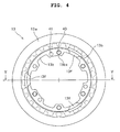
- Fig. 4 is a right-hand side view of the second clutch inner 13.
- Fig. 5 is a sectional view taken along the line V-V of Fig. 4 .
- the spring-receiving-member contact portions 13f illustrated in Fig. 1 are formed at three positions in the inner side of the cylindrical portion of the second clutch inner 13.
- the spring-receiving-member contact portions 13f are formed by extending corresponding parts of the inward flange 13b towards the right-hand side.
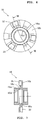
- Fig. 6 is a left-hand side view of the central-cam plate 16.
- Fig. 7 is a sectional view taken along the line VII-VII of Fig. 6 .
- Fig. 8 is a right-hand side view of the central-cam plate 16.
- the central-cam plate 16 includes the boss portion 16a and the outwardly-extending portion 16b, which extends outwards in the radial direction from the boss portion 16a. Splines 16d are formed in the inner side of the boss portion 16a. Accordingly, the central-cam plate 16 is fitted onto the transmission main shaft 2 so as to be incapable of rotating relatively to the transmission main shaft 2.
- the recessed assist cams 35 are formed at three positions in the left-hand side surface of the outwardly-extending portion 16b while the recessed slipper cams 37 are formed at three positions in the right-hand side surface of the outwardly-extending portion 16b.
- the central-cam plate 16 is a member with the recessed cams 35 and 37 formed in both side surfaces thereof.
- the oil holes 16c to lubricate the above-described cam portions are formed in the boss portion 16a.
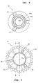
- Fig. 9 is a right-hand side view of the assist-cam plate 17.
- Fig. 10 is a sectional view taken along the line X-X of Fig. 9 . Since the assist-cam plate 17 needs to slide on the outer circumference of the boss portion 16a of the central-cam plate 16, the inner surface of the boss portion 17a of the assist-cam plate 17 is a smooth surface.
- the spline ridges 17b are formed in the outer circumferential portion of the assist-cam plate 17, and engage with the internal spline grooves 13c of the second clutch inner 13.
- the raised assist cams 36 are formed on the right-hand side surface of the assist-cam plate 17. Thin-wall portions 17c are formed in portions located between every two adjacent raised assist cams 36 so that the assist-cam plate 17 can be lighter in weight (see Fig. 9 ).
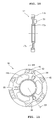
- Fig. 11 is a left-hand side view of the slipper-cam plate 18.
- Fig. 12 is a sectional view taken along the line XII-XII of Fig. 11 . Since the slipper-cam plate 18 needs to slide on the outer circumference of the boss portion 16a of the central-cam plate 16, the inner surface of the boss portion 18a of the slipper-cam plate 18 is a smooth surface.
- Bolt-insertion holes 42 and ventilation holes 43 are formed in the outer peripheral portion of the slipper-cam plate 18.
- the slipper-cam plate 18 is attached to the inward flange 13b of the second clutch inner 13 by inserting the bolts 19 (see Fig. 1 ) respectively into the bolt-insertion holes 42.
- the raised slipper cams 38 are formed on the left-hand side surface of the slipper-cam plate 18.
- Thin-wall portions 18b are formed in portions located between every two adjacent raised slipper cams 38 so that the slipper-cam plate 18 can be lighter in weight (see Fig. 11 ).
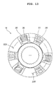
- Fig. 13 is an enlarged left-hand side view of the central-cam plate 16, that is, an enlarged view illustrating the surface in which the recessed assist cams 35 are formed ( Fig. 6 ). Fig. 13 also illustrates the cross-sectional shapes of the raised assist cams 36 that engage with the recessed assist cams 35. In addition, Fig. 13 illustrates, by means of broken lines, the recessed slipper cams 37 formed in the opposite surface of the central-cam plate 16 and also illustrates the raised slipper cams 38 that engage respectively with the recessed slipper cams 37.
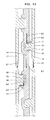
- Fig. 14 is a developed sectional view taken along the line XIV-XIV of Fig. 13 .
- the assist-cam plate 17 and the slipper-cam plate 18 located respectively at the two sides of the central-cam plate 16 are capable of moving by a small amount, independently of and relatively to each other, both in the up-and-down direction and in the right-and-left direction in the drawing with respect to the central-cam plate 16.
- Fig. 1 While the internal combustion engine is not running, the first disc spring 26 pushes the second clutch inner 13. Accordingly, the driving clutch discs 14 and the driven clutch discs 15 are clamped together between the pressurizing portion 13a of the second clutch inner 13 and the pressure-receiving portion 12b of the first clutch inner 12.
- the clutch outer 9 starts rotating. The rotation of the clutch outer 9 rotates the driving clutch discs 14 that engage with the clutch outer 9. The rotation of the driving clutch discs 14 rotates the driven clutch discs 15 that are clamped together with the driving clutch discs 14.
- the rotation of the driven clutch discs 15 rotates the second clutch inner 13 that engages with the driven clutch discs 15.
- the rotation of the second clutch inner 13 rotates the assist-cam plate 17 that engages with the second clutch inner 13 by means of the splines 13c and 17b.
- the rotation of the second clutch inner 13 rotates the slipper-cam plate 18 that is fastened to the second clutch inner 13 with the bolts 19.
- a driving torque A1 acts on the rotating assist-cam plate 17 and on the rotating slipper-cam plate 18.
- the raised assist cams 36 that are formed on the assist-cam plate 17 move in the same direction as the direction of the driving torque A1.
- Each of the raised assist cams 36 is, then, brought into contact with an opposing point 45 that is located on the sloping face of the corresponding recessed assist cam formed in the central-cam plate 16.
- the raised assist cams 36 push the central-cam plate 16 with a pushing force A2 that is equivalent to the driving torque A1, so that the driving torque A1 is transmitted to the central-cam plate 16. Consequently, the central-cam plate 16 is also driven by the driving torque A1.
- This driving torque A1 is then transmitted to the transmission main shaft 2 that is spline-fitted into the central-cam plate 16.
- the driving torque from the internal combustion engine is transmitted to the transmission main shaft 2 also by way of the first clutch inner 12 that is spline-fitted onto the transmission main shaft 2 (see Fig. 1 ). As a consequence, the transmission main shaft 2 is rotated.
- the driving torque A1 acts also on the slipper-cam plate 18, and the slipper cam plate 18 8 rotates together with the assist-cam plate 17. No torque is, however, transmitted from the slipper-cam plate 18 to the central-cam plate 16. This is because a clearance 46 is formed in the rotational direction between each of the raised slipper cams 38 and the corresponding recessed slipper cam 37. What has been described thus far is the mechanism by which the multi-plate clutch 1 transmits the driving force while the vehicle is travelling normally.
- the increase in the driving torque A1 that is transmitted from the internal combustion engine and inputted into the multi-plate clutch 1 via the driven gear 7 is accompanied by the parallel increase in the pushing force A2 exerted by each raised assist cam 36 on the opposing point 45 on the corresponding recessed assist cam 35.
- the sloping-face-direction component of the pushing force A2 (such a component is denoted by A3 in Fig. 14 ) pushes the raised assist cam 36 in the sloping-face direction, so that the assist-cam plate 17 moves, along the sloping faces, in the direction of the component A3.
- the assist-cam plate 17 moves away from the central-cam plate 16.
- the assist-cam plate 17 that is in contact with the second clutch inner 13 with the washer 20 set in between moves away from the second clutch inner 13 against the biasing force of the second disc spring 27.
- the second clutch inner 13 is, however, pushed leftwards by the first disc spring 26, so that the second clutch inner 13 moves in the same direction as the direction of the movement of the assist-cam plate 17. Accordingly, while the second clutch inner 13 is moving, the second clutch inner 13 keeps its contact with the assist-cam plate 17.
- the "force against the clamping force,” that is, the pushing force of the second disc spring 27 is reduced, by a certain amount, by the assist cams 35 and 36 from the state where the pushing force of the first disc spring 26 is balanced with the pushing force of the second disc spring 27.
- the assist-cam plate 17 moves in the sloping-face direction of the recessed assist cams 35, so that the biasing force of the first disc spring 26 can give larger influence than otherwise. Accordingly, the clamping force for the clutch discs 14 and 15 is assisted, and thus the driving torque thus increased is transmitted.
- the second clutch inner 13 is pushed leftwards by the first disc spring 26, but pushes many clutch discs 14 and 15.
- the movement of the second clutch inner 13 is restricted to a certain distance.
- the assist-cam plate 17 that has been in contact with the inward flange 13b of the second clutch inner 13 with the washer 20 set in between eventually departs from the inward flange 13b.
- the clamping force continues to increase along with the increase in the driving torque A1 until the assist-cam plate 17 departs from the second clutch inner 13.
- a further increase in the driving torque A1 that is transmitted from the internal combustion engine and inputted into the multi-plate clutch 1 via the driven gear 7 brings about a further increase in the pushing force A2 exerted by each raised assist cam 36 on the opposing point 45 of the corresponding recessed assist cam 35. Since the sloping-face-direction component A3 of the pushing force A2 increases, the raised assist cams 36 are pushed further in the sloping-face direction. As a consequence, the assist-cam plate 17 departs from the inward flange 13b of the second clutch inner 13. In this event, the position at which each raised assist cam 36 pushes the corresponding recessed assist cam 35 is shifted leftwards along the sloping face, but the raised assist cam 36 will not depart from the recessed assist cam 35.
- the assist-cam plate 17 is in contact with the inward flange 13b of the second clutch inner 13 in Fig. 1 with the washer 20 set in between, the assist-cam plate 17 is separated away from the inward flange 13b of the second clutch inner 13 in the above-described state.
- the biasing force of the first disc spring 26 becomes the only pushing force that acts on the second clutch inner 13. Accordingly, the maximum value of the biasing force of the first disc spring 26 is given as the clamping force for the clutch discs 14 and 15. Note that the clamping force for the clutch discs 14 and 15 cannot exceeds the maximum value of the biasing force of the first disc spring 26.
- the clamping force for the clutch discs 14 and 15 becomes constant at the maximum value of the biasing force of the first disc spring 26.
- the cam mechanism assists the clamping force only within a predetermined value.
- the arrow B1 in Fig. 14 indicates the direction of the back torque transmitted from the wheel via the transmission main shaft 2.
- the recessed slipper cams 37 move in the same direction as the direction of the back torque B1 with respect to the corresponding raised slipper cams 38.
- One of the sloping faces of each recessed slipper cam 37 is then brought into contact with an opposing point 47 of the corresponding raised slipper cam 38.
- the recessed slipper cams 37 thus push the slipper-cam plate 18 via the corresponding raised slipper cams 38 with a pushing force B2 that is equivalent to the above-mentioned back torque B1.
- the increase in the back torque B 1 causes a parallel increase in the pushing force B2 exerted by the sloping face of each recessed slipper cam 37 on the opposing point 47 of the corresponding raised slipper cam 38.
- the sloping-face-direction component of the reaction force to the pushing force B2 (such a component is denoted by B3 in Fig. 14 ) moves the slipper-cam plate 18 along the sloping face in the direction of the reaction-force component B3.
- the movement is transmitted to the second clutch inner 13 that is fastened to the slipper-cam plate 18 with the bolts 19 to form a single united body, and pushes the pressurizing portion 13a of the second clutch inner 13 so as to separate the clutch discs 14 and 15 away from one another.
- the assist-cam plate 17 located at the opposite side of the central-cam plate 16 from the slipper-cam plate 18 is rotating together with the slipper-cam plate 18, but no torque is transmitted from the central-cam plate 16 to the assist-cam plate 17. This is because a clearance 48 is formed in the rotational direction between each of the recessed assist cams 35 and the corresponding raised assist cam 36.
- the assist-cam plate 17 is made to follow, by the biasing force of the second disc spring 27, the slipper-cam plate 18 that moves in the axial direction.
- the slipper-cam plate 18 moves rightwards.
- the rightward movement of the slipper-cam plate 18 reduces the clamping force exerted by the pressurizing portion 13a of the second clutch inner 13 on the clutch discs 14 and 15. Accordingly, the clutch discs 14 and 15 are allowed to slide.
- the slipper-cam mechanism reduces the transmission of the torque, and functions as a back-torque limiter.
- the slipper-cam mechanism alleviates the reverse-input torque at the time of deceleration, and softens the engine braking. Accordingly, the load on the drive train is reduced, and the tires become more wear-resistant.
Landscapes
- Engineering & Computer Science (AREA)
- General Engineering & Computer Science (AREA)
- Mechanical Engineering (AREA)
- Mechanical Operated Clutches (AREA)
- One-Way And Automatic Clutches, And Combinations Of Different Clutches (AREA)
Applications Claiming Priority (1)
| Application Number | Priority Date | Filing Date | Title |
|---|---|---|---|
| JP2008169039A JP5191819B2 (ja) | 2008-06-27 | 2008-06-27 | 多板クラッチ |
Publications (2)
| Publication Number | Publication Date |
|---|---|
| EP2138733A2 true EP2138733A2 (fr) | 2009-12-30 |
| EP2138733A3 EP2138733A3 (fr) | 2014-02-19 |
Family
ID=41119847
Family Applications (1)
| Application Number | Title | Priority Date | Filing Date |
|---|---|---|---|
| EP09154397.5A Withdrawn EP2138733A3 (fr) | 2008-06-27 | 2009-03-05 | Embrayage multi-plaque |
Country Status (3)
| Country | Link |
|---|---|
| US (1) | US8336691B2 (fr) |
| EP (1) | EP2138733A3 (fr) |
| JP (1) | JP5191819B2 (fr) |
Families Citing this family (8)
| Publication number | Priority date | Publication date | Assignee | Title |
|---|---|---|---|---|
| JP4785668B2 (ja) * | 2006-08-02 | 2011-10-05 | 本田技研工業株式会社 | 多板クラッチ |
| JP5171779B2 (ja) * | 2009-09-30 | 2013-03-27 | 本田技研工業株式会社 | 多板クラッチ装置 |
| JP4939585B2 (ja) * | 2009-09-30 | 2012-05-30 | 本田技研工業株式会社 | 多板クラッチ装置 |
| JP5377459B2 (ja) * | 2010-11-05 | 2013-12-25 | 本田技研工業株式会社 | 多板クラッチ装置 |
| JP6714028B2 (ja) * | 2018-03-14 | 2020-06-24 | 株式会社エクセディ | クラッチ装置 |
| JP7231333B2 (ja) * | 2018-03-16 | 2023-03-01 | 株式会社エフ・シー・シー | クラッチ装置 |
| JP7209521B2 (ja) * | 2018-12-05 | 2023-01-20 | 株式会社エフ・シー・シー | 動力伝達装置 |
| JP7430505B2 (ja) | 2019-09-30 | 2024-02-13 | 株式会社Subaru | 整流装置 |
Citations (1)
| Publication number | Priority date | Publication date | Assignee | Title |
|---|---|---|---|---|
| JP2008038954A (ja) | 2006-08-02 | 2008-02-21 | Honda Motor Co Ltd | 多板クラッチ |
Family Cites Families (8)
| Publication number | Priority date | Publication date | Assignee | Title |
|---|---|---|---|---|
| US4189042A (en) * | 1977-12-08 | 1980-02-19 | Facet Enterprises, Inc. | Constant torque friction clutch |
| JP3107692B2 (ja) * | 1993-12-17 | 2000-11-13 | ヤマハ発動機株式会社 | 多板摩擦クラッチ |
| JP3378097B2 (ja) * | 1994-09-29 | 2003-02-17 | 本田技研工業株式会社 | 摩擦クラッチ |
| US6378682B1 (en) * | 1998-10-16 | 2002-04-30 | New Venture Gear, Inc. | Multi-function control valve for hydraulic coupling |
| JP3070083U (ja) * | 1999-12-28 | 2000-07-14 | 株式会社藤田商会 | クラッチ装置 |
| JP2002098165A (ja) * | 2000-09-21 | 2002-04-05 | Jatco Transtechnology Ltd | 発進クラッチ |
| US7104380B2 (en) * | 2004-09-15 | 2006-09-12 | Ford Global Technologies, Llc | Dual area piston for transmission clutch and sequential control therefor |
| JP4662896B2 (ja) * | 2006-08-07 | 2011-03-30 | 本田技研工業株式会社 | 多板クラッチ |
-
2008
- 2008-06-27 JP JP2008169039A patent/JP5191819B2/ja not_active Expired - Fee Related
-
2009
- 2009-03-05 EP EP09154397.5A patent/EP2138733A3/fr not_active Withdrawn
- 2009-03-11 US US12/402,181 patent/US8336691B2/en not_active Expired - Fee Related
Patent Citations (1)
| Publication number | Priority date | Publication date | Assignee | Title |
|---|---|---|---|---|
| JP2008038954A (ja) | 2006-08-02 | 2008-02-21 | Honda Motor Co Ltd | 多板クラッチ |
Also Published As
| Publication number | Publication date |
|---|---|
| EP2138733A3 (fr) | 2014-02-19 |
| US20090321212A1 (en) | 2009-12-31 |
| JP2010007789A (ja) | 2010-01-14 |
| JP5191819B2 (ja) | 2013-05-08 |
| US8336691B2 (en) | 2012-12-25 |
Similar Documents
| Publication | Publication Date | Title |
|---|---|---|
| EP2138733A2 (fr) | Embrayage multi-plaque | |
| JP4662896B2 (ja) | 多板クラッチ | |
| EP2778457B1 (fr) | Dispositif de transmission de puissance | |
| EP2037142B1 (fr) | Appareil de transmission de couple | |
| JP4797008B2 (ja) | 多板クラッチ | |
| JP4785668B2 (ja) | 多板クラッチ | |
| US9353803B2 (en) | Power transmitting apparatus | |
| US8424662B2 (en) | Multi-plate clutch system | |
| EP2686567B1 (fr) | Poulie à embrayage sensible au couple asymétrique | |
| EP3409965B1 (fr) | Dispositif de transmission de puissance | |
| US8490768B2 (en) | Multi-plate clutch system | |
| EP2039950B1 (fr) | Appareil de transmission de puissance | |
| CN111566373B (zh) | 动力传递装置 | |
| EP2093445B1 (fr) | Embrayage à friction | |
| EP1253339B1 (fr) | Embrayage | |
| JP4662899B2 (ja) | 多板クラッチ | |
| EP3739231B1 (fr) | Dispositif de transmission de puissance | |
| JP5074230B2 (ja) | 多板クラッチ | |
| CN113167338A (zh) | 动力传递装置 | |
| US20210131504A1 (en) | Clutch basket assembly | |
| US9797460B2 (en) | Clutch apparatus employing dual concentric clutches |
Legal Events
| Date | Code | Title | Description |
|---|---|---|---|
| PUAI | Public reference made under article 153(3) epc to a published international application that has entered the european phase |
Free format text: ORIGINAL CODE: 0009012 |
|
| AK | Designated contracting states |
Kind code of ref document: A2 Designated state(s): AT BE BG CH CY CZ DE DK EE ES FI FR GB GR HR HU IE IS IT LI LT LU LV MC MK MT NL NO PL PT RO SE SI SK TR |
|
| AX | Request for extension of the european patent |
Extension state: AL BA RS |
|
| PUAL | Search report despatched |
Free format text: ORIGINAL CODE: 0009013 |
|
| AK | Designated contracting states |
Kind code of ref document: A3 Designated state(s): AT BE BG CH CY CZ DE DK EE ES FI FR GB GR HR HU IE IS IT LI LT LU LV MC MK MT NL NO PL PT RO SE SI SK TR |
|
| AX | Request for extension of the european patent |
Extension state: AL BA RS |
|
| RIC1 | Information provided on ipc code assigned before grant |
Ipc: F16D 13/56 20060101AFI20140114BHEP |
|
| 17P | Request for examination filed |
Effective date: 20140812 |
|
| RBV | Designated contracting states (corrected) |
Designated state(s): AT BE BG CH CY CZ DE DK EE ES FI FR GB GR HR HU IE IS IT LI LT LU LV MC MK MT NL NO PL PT RO SE SI SK TR |
|
| AKX | Designation fees paid |
Designated state(s): DE ES IT |
|
| 17Q | First examination report despatched |
Effective date: 20160624 |
|
| GRAP | Despatch of communication of intention to grant a patent |
Free format text: ORIGINAL CODE: EPIDOSNIGR1 |
|
| INTG | Intention to grant announced |
Effective date: 20170721 |
|
| STAA | Information on the status of an ep patent application or granted ep patent |
Free format text: STATUS: THE APPLICATION IS DEEMED TO BE WITHDRAWN |
|
| 18D | Application deemed to be withdrawn |
Effective date: 20171201 |