EP2138659A2 - Dichtelement für einen Kolben eines Antriebs einer Tür oder dergl. - Google Patents
Dichtelement für einen Kolben eines Antriebs einer Tür oder dergl. Download PDFInfo
- Publication number
- EP2138659A2 EP2138659A2 EP09163839A EP09163839A EP2138659A2 EP 2138659 A2 EP2138659 A2 EP 2138659A2 EP 09163839 A EP09163839 A EP 09163839A EP 09163839 A EP09163839 A EP 09163839A EP 2138659 A2 EP2138659 A2 EP 2138659A2
- Authority
- EP
- European Patent Office
- Prior art keywords
- sealing element
- piston
- sealing
- receiving space
- element according
- Prior art date
- Legal status (The legal status is an assumption and is not a legal conclusion. Google has not performed a legal analysis and makes no representation as to the accuracy of the status listed.)
- Withdrawn
Links
- 238000007789 sealing Methods 0.000 title claims abstract description 91
- 239000012530 fluid Substances 0.000 claims abstract description 6
- 230000015572 biosynthetic process Effects 0.000 abstract description 3
- 230000004308 accommodation Effects 0.000 abstract 2
- 230000000284 resting effect Effects 0.000 abstract 1
- 238000004519 manufacturing process Methods 0.000 description 3
- 238000001746 injection moulding Methods 0.000 description 2
- 230000000694 effects Effects 0.000 description 1
- 238000004146 energy storage Methods 0.000 description 1
Images

Classifications
-
- E—FIXED CONSTRUCTIONS
- E05—LOCKS; KEYS; WINDOW OR DOOR FITTINGS; SAFES
- E05F—DEVICES FOR MOVING WINGS INTO OPEN OR CLOSED POSITION; CHECKS FOR WINGS; WING FITTINGS NOT OTHERWISE PROVIDED FOR, CONCERNED WITH THE FUNCTIONING OF THE WING
- E05F3/00—Closers or openers with braking devices, e.g. checks; Construction of pneumatic or liquid braking devices
- E05F3/04—Closers or openers with braking devices, e.g. checks; Construction of pneumatic or liquid braking devices with liquid piston brakes
- E05F3/12—Special devices controlling the circulation of the liquid, e.g. valve arrangement
-
- E—FIXED CONSTRUCTIONS
- E05—LOCKS; KEYS; WINDOW OR DOOR FITTINGS; SAFES
- E05F—DEVICES FOR MOVING WINGS INTO OPEN OR CLOSED POSITION; CHECKS FOR WINGS; WING FITTINGS NOT OTHERWISE PROVIDED FOR, CONCERNED WITH THE FUNCTIONING OF THE WING
- E05F3/00—Closers or openers with braking devices, e.g. checks; Construction of pneumatic or liquid braking devices
- E05F3/22—Additional arrangements for closers, e.g. for holding the wing in opened or other position
-
- E—FIXED CONSTRUCTIONS
- E05—LOCKS; KEYS; WINDOW OR DOOR FITTINGS; SAFES
- E05Y—INDEXING SCHEME ASSOCIATED WITH SUBCLASSES E05D AND E05F, RELATING TO CONSTRUCTION ELEMENTS, ELECTRIC CONTROL, POWER SUPPLY, POWER SIGNAL OR TRANSMISSION, USER INTERFACES, MOUNTING OR COUPLING, DETAILS, ACCESSORIES, AUXILIARY OPERATIONS NOT OTHERWISE PROVIDED FOR, APPLICATION THEREOF
- E05Y2800/00—Details, accessories and auxiliary operations not otherwise provided for
- E05Y2800/10—Additional functions
- E05Y2800/12—Sealing
-
- E—FIXED CONSTRUCTIONS
- E05—LOCKS; KEYS; WINDOW OR DOOR FITTINGS; SAFES
- E05Y—INDEXING SCHEME ASSOCIATED WITH SUBCLASSES E05D AND E05F, RELATING TO CONSTRUCTION ELEMENTS, ELECTRIC CONTROL, POWER SUPPLY, POWER SIGNAL OR TRANSMISSION, USER INTERFACES, MOUNTING OR COUPLING, DETAILS, ACCESSORIES, AUXILIARY OPERATIONS NOT OTHERWISE PROVIDED FOR, APPLICATION THEREOF
- E05Y2800/00—Details, accessories and auxiliary operations not otherwise provided for
- E05Y2800/26—Form or shape
- E05Y2800/28—Form or shape tubular, annular
-
- E—FIXED CONSTRUCTIONS
- E05—LOCKS; KEYS; WINDOW OR DOOR FITTINGS; SAFES
- E05Y—INDEXING SCHEME ASSOCIATED WITH SUBCLASSES E05D AND E05F, RELATING TO CONSTRUCTION ELEMENTS, ELECTRIC CONTROL, POWER SUPPLY, POWER SIGNAL OR TRANSMISSION, USER INTERFACES, MOUNTING OR COUPLING, DETAILS, ACCESSORIES, AUXILIARY OPERATIONS NOT OTHERWISE PROVIDED FOR, APPLICATION THEREOF
- E05Y2900/00—Application of doors, windows, wings or fittings thereof
- E05Y2900/10—Application of doors, windows, wings or fittings thereof for buildings or parts thereof
- E05Y2900/13—Type of wing
- E05Y2900/132—Doors
Definitions
- the invention relates to a sealing element for the piston of a drive of a door or the like. According to the preamble of claim 1.
- the door closer for manual or - by means of a hydraulic pump - motorized opening a wing of a door or a window known.
- the door closer comprises a receiving space filled with hydraulic fluid, in which a piston is guided, which is acted upon by a closing spring for closing the wing.
- On the piston sealing elements for low-friction storage and / or guidance of the piston are arranged.
- the sealing elements may not compensate for manufacturing tolerances.
- the invention has the object of providing a cost-effective, improved sealing element.
- Generic drives for doors as these, for example, from the above DE 198 08 292 A1 are known, have a piston and designed as a spring energy storage, which is charged by manual opening or by a motor drive and causes the wing is guided after opening again in its closed position.
- drives are used which have an articulated joint Linkage or via a guided in a slide through a sliding block sliding arm cause the force to the door.
- the piston cooperates with an output shaft, which is operatively connected to the sliding arm or the linkage for actuating the wing and arranged in a receiving space filled with a hydraulic fluid.
- an output shaft which is operatively connected to the sliding arm or the linkage for actuating the wing and arranged in a receiving space filled with a hydraulic fluid.
- In the housing profile of the drive usually one or more channels are arranged, which allow an overflow of the hydraulic fluid from one piston side to the other, wherein for controlling the behavior of the drive valves may be arranged in the channels.
- sealing elements are arranged on the piston in the region of the front ends. The sealing elements can be formed the same or different.
- the piston has to receive the sealing element on a tapered extension in diameter.
- the sealing element may be annular. However, other piston cross-sections, for example, oval or rectangular, possible, wherein the sealing element then also has a corresponding shape.
- the sealing element can be advantageously designed as a plastic part produced inexpensively by injection molding.
- the sealing element has a supporting body which serves to receive the sealing element on the extension of the piston.
- the support body according to the invention recesses for the formation of webs with uniform wall thicknesses, whereby the sealing element is accurate and distortion and stress-free to produce.
- one or more locking elements may be arranged, which engage in korespendierende recesses on the extension of the piston to set the sealing element on the piston.
- a sealing lip is arranged, which is spaced by a cutout relative to the support body.
- the sealing lip is connected to the base of the free cut with the support body. Due to the particularly deep cut-free advantageously results in a high elasticity of the sealing lip.
- the sealing lip is directed outwards, whereby the sealing surface formed on the sealing lip is inclined in the unassembled state of the sealing element relative to the central axis.
- the sealing lip After the assembly of the piston provided with the sealing element in the receiving space, the sealing lip is under tension in contact with the inner wall of the receiving space, wherein the sealing region of the sealing lip advantageously thereby over the entire surface of the inner wall of the receiving space. Due to the high accuracy of fit and the optimal, flat contact area of the sealing area under tension, an improved and cost-effective sealing and guiding of the piston is effected in the receiving space, and manufacturing tolerances of the drive can be compensated.
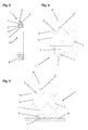
- a piston 2 of a manual or automatic drive is shown.
- the piston 2 has a projection 3 for receiving a sealing element 1, wherein the sealing element 1, the piston 2 against a in the Fig. 1 not shown Inner wall 12 of a receiving space for the piston 2 seals and the piston 2 in the receiving space leads.
- FIGS. 2 to 5 show the sealing element 1 as a single part, wherein the sealing element 1 is annular. Since other piston shapes, such as oval or rectangular, are possible, the sealing element 1 may also be shaped accordingly round.
- the sealing element 1 can be advantageously designed as a cost-effectively manufactured by injection molding plastic part.
- the sealing element 1 has a support body 6 for receiving the sealing element 1 on the extension 3 of the piston 2. At the inner diameter of the support body 6 has at least one locking element 11 which engages in at least one korespend Schl recess on the extension 3 of the piston 2 to set the sealing element 1 on the piston 2.
- the support body 6 according to the invention recesses 8 for the formation of webs 9 on. Due to the uniform, relatively thin wall thicknesses of the webs 9 a precisely fitting and distortion-free and tension-free sealing element 1 is created.
- the inner webs 9 have notches 10 directed towards the recesses 8, which prevent the recesses 8 from being closed against the hydraulic fluid in the receiving space when a closing spring rests on the supporting body 6, whereby a pressure difference between the receiving space and the recesses 8 is compensated ,
- a sealing lip 4 is arranged, which is spaced with a cutout 7 relative to the support body 6.
- the sealing lip 4 is connected only at the bottom of the cutout 7 with the support body 6. Due to the very deep cutout 7, the elasticity of the sealing element 1 with respect to the sealing lip 4 is further improved.
- Fig. 4 is an enlarged view B of the section according to Fig. 3 shown by the sealing element 1, wherein the advantageous embodiment of the sealing lip 4 with a sealing region 5, here in the non-installed state of the sealing element 1, is shown.
- the sealing lip 4 is directed outwards, whereby the sealing region. 5 relative to the support body 6 and thus inclined relative to the central axis of the piston 2.
- the sealing lip 4 comes under tension into contact with the inner wall 12 of the receiving space, as shown in the Fig. 5 is shown.
- the sealing region 5 of the sealing lip 4 is advantageous over the entire area under tension into contact with the inner wall 12 of the receiving space, whereby an optimal sealing effect and guidance of the piston 2 is achieved. Due to the full surface contact of the sealing lip 4 manufacturing tolerances of the receiving space are compensated.
Landscapes
- Pistons, Piston Rings, And Cylinders (AREA)
- Actuator (AREA)
Abstract
Description
- Die Erfindung betrifft ein Dichtelement für den Kolben eines Antriebs einer Tür oder dergl. nach dem Oberbegriff des Anspruchs 1.
- Aus der
DE 198 08 292 A1 ist ein Türschließer zum manuellen oder - mittels einer Hydraulikpumpe - motorischen Öffnen eines Flügels einer Tür oder eines Fensters bekannt. Der Türschließer umfasst einen mit einer mit Hydraulikflüssigkeit gefüllten Aufnahmeraum, in welchem ein Kolben geführt ist, der zum Schließen des Flügels von einer Schließerfeder beaufschlagt ist. An dem Kolben sind Dichtelemente zur reibungsarmen Lagerung und/oder Führung des Kolbens angeordnet. - Die Dichtelemente können möglicherweise fertigungsbedingte Toleranzen nicht ausgleichen.
- Der Erfindung liegt die Aufgabe zugrunde, ein kostengünstiges, verbessertes Dichtelement auszubilden.
- Die Aufgabe wird durch die Merkmale des Anspruchs 1 gelöst.
- Die Unteransprüche bilden vorteilhafte Ausgestaltungsmöglichkeiten der Erfindung.
- Gattungsgemäße Antriebe für Türen, wie diese beispielsweise aus der vorstehend genannten
DE 198 08 292 A1 bekannt sind, weisen einen Kolben und einen als Feder ausgebildeten Energiespeicher auf, welcher durch manuelles Öffnen oder durch einen motorischen Antrieb aufgeladen wird und der bewirkt, dass der Flügel nach dem Öffnen wieder in seine Geschlossenlage geführt wird. Bei Drehtüren werden dazu Antriebe eingesetzt, welche über ein gelenkig miteinander verbundenes Gestänge oder über einen in einer Gleitschiene durch einen Gleitstein geführten Gleitarm die Krafteinleitung auf die Tür bewirken. - Der Kolben wirkt mit einer Abtriebswelle zusammen, die mit dem Gleitarm oder dem Gestänge zur Betätigung des Flügels wirkverbunden und in einem mit einer Hydraulikflüssigkeit befüllten Aufnahmeraum angeordnet ist. Im Gehäuseprofil des Antriebs sind üblicherweise ein oder mehrere Kanäle angeordnet, welche ein Überströmen der Hydraulikflüssigkeit von einer Kolbenseite zur anderen ermöglichen, wobei zur Steuerung des Verhaltens des Antriebs Ventile in den Kanälen angeordnet sein können. Zur Abdichtung und Führung gegen die Innenwandung des Aufnahmeraums sind am Kolben im Bereich der stirnseitigen Enden Dichtelemente angeordnet. Die Dichtelemente können dabei gleich oder unterschiedlich ausgebildet sein.
- Der Kolben weist dabei zur Aufnahme des Dichtelements einen im Durchmesser verjüngten Fortsatz auf. Das Dichtelement kann ringförmig ausgebildet sein. Es sind jedoch auch andere Kolbenquerschnitte, beispielsweise oval oder rechteckig, möglich, wobei das Dichtelement dann auch eine dementsprechende Form aufweist. Das Dichtelement kann vorteilhaft als ein kostengünstig im Spritzgussverfahren hergestelltes Kunststoffteil ausgebildet sein.
- Das Dichtelement weist einen Tragkörper auf, welcher zur Aufnahme des Dichtelements auf dem Fortsatz des Kolbens dient. Um eine vorteilhaft hohe Elastizität des Dichtelements zu erhalten, weist der Tragkörper erfindungsgemäß Aussparungen zur Ausbildung von Stegen mit gleichmäßigen Wandstärken auf, wodurch das Dichtelement passgenau sowie verzugs- und spannungsfrei herstellbar ist. Am inneren Durchmesser des Tragkörpers können ein oder mehrere Rastelemente angeordnet sein, welche in korespendierende Ausnehmungen am Fortsatz des Kolbens eingreifen, um das Dichtelement am Kolben festzulegen.
- Am äußeren Umfang des Dichtelements ist eine Dichtlippe angeordnet, die durch einen Freischnitt gegenüber dem Tragkörper beabstandet ist. Die Dichtlippe ist am Grund des Freischnittes mit dem Tragkörper verbunden. Durch den besonders tiefen Freischnitt ergibt sich vorteilhaft eine hohe Elastizität der Dichtlippe.
- Die Dichtlippe ist nach außen gerichtet, wodurch die an der Dichtlippe ausgebildete Dichtfläche in unmontiertem Zustand des Dichtelements gegenüber der Mittelachse geneigt ist.
- Nach erfolgter Montage des mit dem Dichtelement versehenen Kolbens im Aufnahmeraum befindet sich die Dichtlippe unter Spannung in Anlage mit der Innenwandung des Aufnahmeraums, wobei der Dichtbereich der Dichtlippe vorteilhaft dadurch vollflächig an der Innenwandung des Aufnahmeraums anliegt. Durch die hohe Passgenauigkeit und die optimale, flächige Anlage des Dichtbereichs unter Spannung wird eine verbesserte und kostengünstige Dichtung und Führung des Kolbens im Aufnahmeraum bewirkt, und Fertigungstoleranzen des Antriebs können ausgeglichen werden.
- Im Nachfolgenden wird ein Ausführungsbeispiel in der Zeichnung anhand der Figuren näher erläutert.
- Dabei zeigen:
- Fig. 1
- einen Schnitt durch eine Kolben eines Antriebs mit einem angeordnetem Dichtelement;
- Fig. 2
- eine Draufsicht auf das Dichtelement als Einzelteil;
- Fig. 3
- den Schnitt A-A gemäß
Fig. 2 durch das Dichtelement; - Fig. 4
- den vergrößerten Ausschnitt B eines Teilbereichs des Schnittes A-A gemäß
Fig. 3 ; - Fig. 5
- eine weitere Darstellung des Ausschnitts B gemäß
Fig. 4 , jedoch mit Darstellung des Dichtelements in eingebautem Zustand des Kolbens, wobei sich das Dichtelement in Anlage mit der Innenwandung des Aufnahmeraums befindet. - In der
Fig. 1 ist ein Kolben 2 eines manuellen oder automatischen Antriebs gezeigt. Der Kolben 2 weist zur Aufnahme eines Dichtelements 1 einen Fortsatz 3 auf, wobei das Dichtelement 1 den Kolben 2 gegen eine in derFig. 1 nicht dargestellten Innenwandung 12 eines Aufnahmeraums für den Kolben 2 abdichtet und den Kolben 2 im Aufnahmeraum führt. - Die
Figuren 2 bis 5 zeigen das Dichtelement 1 als Einzelteil, wobei das Dichtelement 1 ringförmig ausgebildet ist. Da auch andere Kolbenformen, beispielsweise oval oder rechteckig, möglich sind, kann das Dichtelement 1 auch dementsprechend unrund geformt sein. Das Dichtelement 1 kann dabei vorteilhaft als ein kostengünstig im Spritzgussverfahren hergestelltes Kunststoffteil ausgebildet sein. - Das Dichtelement 1 weist einen Tragkörper 6 zur Aufnahme des Dichtelements 1 auf dem Fortsatz 3 des Kolbens 2 auf. Am inneren Durchmesser weist der Tragkörper 6 mindestens ein Rastelement 11 auf, welches in mindestens eine korespendierende Ausnehmung am Fortsatz 3 des Kolbens 2 eingreift, um das Dichtelement 1 am Kolben 2 festzulegen. Um vorteilhaft eine hohe Elastizität des Dichtelements 1 zur Begünstigung des Verrastens mit dem Kolben 1 zu erhalten, weist der Tragkörper 6 erfindungsgemäß Aussparungen 8 zur Ausbildung von Stegen 9 auf. Durch die gleichmäßigen, relativ dünnen Wandstärken der Stege 9 wird ein passgenaues sowie verzugs- und spannungsfreies Dichtelement 1 geschaffen. Die inneren Stege 9 weisen zu den Aussparungen 8 hin gerichtete Kerben 10 auf, welche verhindern, dass bei Aufliegen einer Schließerfeder auf dem Tragkörper 6 die Aussparungen 8 gegenüber der Hydraulikflüssigkeit im Aufnahmeraum abgeschlossen sind, wodurch ein Druckunterschied zwischen dem Aufnahmeraum und den Aussparungen 8 ausgeglichen wird.
- Am äußeren Umfang des Dichtelements 1 ist eine Dichtlippe 4 angeordnet, welche mit einem Freischnitt 7 gegenüber dem Tragkörper 6 beabstandet ist. Die Dichtlippe 4 ist lediglich am Grund des Freischnittes 7 mit dem Tragkörper 6 verbunden. Durch den sehr tiefen Freischnitt 7 ist die Elastizität des Dichtelement 1 in Bezug auf die Dichtlippe 4 weiter verbessert.
- In der
Fig. 4 ist eine vergrößerte Ansicht B des Schnitts gemäßFig. 3 durch das Dichtelement 1 gezeigt, wobei die vorteilhafte Ausgestaltung der Dichtlippe 4 mit einem Dichtbereich 5, hier in nicht eingebautem Zustand des Dichtelements 1, gezeigt ist. Die Dichtlippe 4 ist nach außen gerichtet, wodurch der Dichtbereich 5 gegenüber dem Tragkörper 6 und somit gegenüber der Mittelachse des Kolbens 2 geneigt ist. - Nach erfolgter Montage des mit dem Dichtelement 1 versehenen Kolbens 2 in dem Aufnahmeraum kommt die Dichtlippe 4 unter Spannung in Anlage mit der Innenwandung 12 des Aufnahmeraums, wie es in der
Fig. 5 gezeigt ist. Dabei kommt der Dichtbereich 5 der Dichtlippe 4 vorteilhaft vollflächig unter Spannung in Anlage mit der Innenwandung 12 des Aufnahmeraums, wodurch eine optimale Dichtwirkung und Führung des Kolbens 2 erreicht wird. Durch die vollflächige Anlage der Dichtlippe 4 werden fertigungsbedingte Toleranzen des Aufnahmeraums ausgeglichen. -
- 1
- Dichtelement
- 2
- Kolben
- 3
- Fortsatz
- 4
- Dichtlippe
- 5
- Dichtbereich
- 6
- Tragkörper
- 7
- Freischnitt
- 8
- Aussparung
- 9
- Steg
- 10
- Kerbe
- 11
- Rastelement
- 12
- Innenwandung Aufnahmeraum
Claims (7)
- Dichtelement (1) für einen Kolben (2) eines Antriebs einer Tür oder dergl., wobei der Kolben (2) in einem mit einer Hydraulikflüssigkeit gefüllten Aufnahmeraum verschiebbar angeordnet ist, und wobei das Dichtelement (1) den Kolben (2) gegenüber die Innenwandung (12) des Aufnahmeraums führt und abdichtet,
dadurch gekennzeichnet,
dass das Dichtelement (1) einen Tragkörper (6) aufweist, in welchem Aussparungen (8) zur Ausbildung von Stegen (9) angeordnet sind. - Dichtelement nach Anspruch 1,
dadurch gekennzeichnet, dass eine Dichtlippe (4) mittels eines Freischnittes (7) zum Tragkörper (6) beabstandet angeordnet ist. - Dichtelement nach Anspruch 2,
dadurch gekennzeichnet, dass die Dichtlippe (4) am Grund des Freischnittes (7) mit dem Tragkörper (6) verbunden ist. - Dichtelement nach Anspruch 2,
dadurch gekennzeichnet, dass die Dichtlippe (4) des Dichtelements (1) nach außen weist. - Dichtelement nach Anspruch 2,
dadurch gekennzeichnet, dass die Dichtlippe (4) einen Dichtbereich (5) aufweist, welcher in montiertem Zustand des Kolbens (2) mit Dichtelement (1) im Aufnahmeraum unter Spannung vollflächig an einer Innenwandung (12) des Aufnahmeraums anliegt. - Dichtelement nach Anspruch 1,
dadurch gekennzeichnet, dass das Dichtelement (1) Rastelemente (11) aufweist, welche mit korrespondierenden, an einem Fortsatz (3) des Kolbens (2) angeordneten Aussparungen zur Festlegung des Dichtelements (1) am Kolben (2) zusammenwirken. - Dichtelement nach Anspruch 1,
dadurch gekennzeichnet, dass an Stegen (9) Kerben (10) zum Ausgleich eines Druckunterschieds zwischen dem Aufnahmeraum und den Aussparungen (8) angeordnet sind.
Applications Claiming Priority (1)
| Application Number | Priority Date | Filing Date | Title |
|---|---|---|---|
| DE200810030059 DE102008030059B3 (de) | 2008-06-27 | 2008-06-27 | Dichtelement für einen Kolben eines Antriebs einer Tür oder dergl. |
Publications (2)
| Publication Number | Publication Date |
|---|---|
| EP2138659A2 true EP2138659A2 (de) | 2009-12-30 |
| EP2138659A3 EP2138659A3 (de) | 2014-02-19 |
Family
ID=41011456
Family Applications (1)
| Application Number | Title | Priority Date | Filing Date |
|---|---|---|---|
| EP09163839.5A Withdrawn EP2138659A3 (de) | 2008-06-27 | 2009-06-26 | Dichtelement für einen Kolben eines Antriebs einer Tür oder dergl. |
Country Status (2)
| Country | Link |
|---|---|
| EP (1) | EP2138659A3 (de) |
| DE (1) | DE102008030059B3 (de) |
Citations (1)
| Publication number | Priority date | Publication date | Assignee | Title |
|---|---|---|---|---|
| DE19808292A1 (de) | 1998-02-27 | 1999-09-02 | Geze Gmbh & Co | Türschließer |
Family Cites Families (5)
| Publication number | Priority date | Publication date | Assignee | Title |
|---|---|---|---|---|
| CH146640A (de) * | 1929-03-15 | 1931-04-30 | Huhn Gustav | Kammerpackung. |
| AT229754B (de) * | 1962-02-13 | 1963-10-10 | Grundmann Geb | Kolben mit Manschettendichtung |
| DE2157800A1 (de) * | 1971-11-22 | 1973-05-30 | Ver Baubeschlag Gretsch Co | Rohrtuerschliesser |
| FR2381948A1 (fr) * | 1977-02-28 | 1978-09-22 | Sankyo Seiki Seisakusho Kk | Piston formant cremaillere pour systeme hydraulique, notamment pour dispositif de fermeture de porte |
| US5224413A (en) * | 1992-07-13 | 1993-07-06 | Mosier Industries, Inc. | Impact dampening means for power cylinders |
-
2008
- 2008-06-27 DE DE200810030059 patent/DE102008030059B3/de not_active Withdrawn - After Issue
-
2009
- 2009-06-26 EP EP09163839.5A patent/EP2138659A3/de not_active Withdrawn
Patent Citations (1)
| Publication number | Priority date | Publication date | Assignee | Title |
|---|---|---|---|---|
| DE19808292A1 (de) | 1998-02-27 | 1999-09-02 | Geze Gmbh & Co | Türschließer |
Also Published As
| Publication number | Publication date |
|---|---|
| DE102008030059B3 (de) | 2010-04-15 |
| EP2138659A3 (de) | 2014-02-19 |
Similar Documents
| Publication | Publication Date | Title |
|---|---|---|
| EP3645818B1 (de) | Dämpfer | |
| DE102013004850B4 (de) | Spannvorrichtung mit Blattfedermembran | |
| EP2006480A1 (de) | Dämpfer für Möbel | |
| EP2425079B1 (de) | Dämpfer für möbel | |
| DE102011017795A1 (de) | Türschließer | |
| EP1431494B1 (de) | Antrieb für einen Flügel einer Tür oder eines Fensters | |
| EP1293633B1 (de) | Türschliesser | |
| WO2013124138A1 (de) | Ventil | |
| DE102019203904A1 (de) | Doppelklappenventil für eine Flüssigfiltereinrichtung | |
| DE102008030059B3 (de) | Dichtelement für einen Kolben eines Antriebs einer Tür oder dergl. | |
| DE102008030060B4 (de) | Dichtelement für einen Kolben eines Antriebs einer Tür oder dergl. | |
| EP2841793B1 (de) | Dämpfer | |
| DE10026360A1 (de) | Kolbenstangenführung | |
| EP2518251A2 (de) | Türschließer | |
| EP2458124B1 (de) | Ventil für einen Antrieb einer Tür oder eines Fensters | |
| DE202016101010U1 (de) | Stellventil | |
| DE102016222918A1 (de) | Luftsteuereinrichtung | |
| WO2004003412A1 (de) | Schieberventil | |
| DE19822498A1 (de) | Türantrieb | |
| EP1619568A2 (de) | Thermostatventil | |
| DE3932269A1 (de) | Druckbegrenzungsventil | |
| DE10323836B3 (de) | Druckventil mit Dichtungsvorrichtung, insbesondere für die Kraftfahrzeugtechnik | |
| DE10322916B4 (de) | Ventil zum Steuern eines Fluids | |
| DE102006038110A1 (de) | Türschließer | |
| EP1577540B1 (de) | Steuerventil für ein Einspritzventil |
Legal Events
| Date | Code | Title | Description |
|---|---|---|---|
| PUAI | Public reference made under article 153(3) epc to a published international application that has entered the european phase |
Free format text: ORIGINAL CODE: 0009012 |
|
| AK | Designated contracting states |
Kind code of ref document: A2 Designated state(s): AT BE BG CH CY CZ DE DK EE ES FI FR GB GR HR HU IE IS IT LI LT LU LV MC MK MT NL NO PL PT RO SE SI SK TR |
|
| PUAL | Search report despatched |
Free format text: ORIGINAL CODE: 0009013 |
|
| AK | Designated contracting states |
Kind code of ref document: A3 Designated state(s): AT BE BG CH CY CZ DE DK EE ES FI FR GB GR HR HU IE IS IT LI LT LU LV MC MK MT NL NO PL PT RO SE SI SK TR |
|
| AX | Request for extension of the european patent |
Extension state: AL BA RS |
|
| RIC1 | Information provided on ipc code assigned before grant |
Ipc: E05F 3/10 20060101AFI20140110BHEP Ipc: E05F 3/12 20060101ALI20140110BHEP |
|
| 17P | Request for examination filed |
Effective date: 20140813 |
|
| RBV | Designated contracting states (corrected) |
Designated state(s): AT BE BG CH CY CZ DE DK EE ES FI FR GB GR HR HU IE IS IT LI LT LU LV MC MK MT NL NO PL PT RO SE SI SK TR |
|
| 17Q | First examination report despatched |
Effective date: 20150204 |
|
| STAA | Information on the status of an ep patent application or granted ep patent |
Free format text: STATUS: THE APPLICATION HAS BEEN WITHDRAWN |
|
| 18W | Application withdrawn |
Effective date: 20160311 |