EP2138639A1 - Control unit for operating machine - Google Patents
Control unit for operating machine Download PDFInfo
- Publication number
- EP2138639A1 EP2138639A1 EP08721069A EP08721069A EP2138639A1 EP 2138639 A1 EP2138639 A1 EP 2138639A1 EP 08721069 A EP08721069 A EP 08721069A EP 08721069 A EP08721069 A EP 08721069A EP 2138639 A1 EP2138639 A1 EP 2138639A1
- Authority
- EP
- European Patent Office
- Prior art keywords
- attachment
- hydraulic
- monitor
- attaching
- work machine
- Prior art date
- Legal status (The legal status is an assumption and is not a legal conclusion. Google has not performed a legal analysis and makes no representation as to the accuracy of the status listed.)
- Withdrawn
Links
- 239000012530 fluid Substances 0.000 claims abstract description 18
- 230000000452 restraining effect Effects 0.000 claims description 3
- 239000010720 hydraulic oil Substances 0.000 description 10
- 238000000034 method Methods 0.000 description 9
- 230000006870 function Effects 0.000 description 7
- 230000000694 effects Effects 0.000 description 3
- 230000005281 excited state Effects 0.000 description 2
- 239000000446 fuel Substances 0.000 description 2
- 239000004576 sand Substances 0.000 description 2
- XLYOFNOQVPJJNP-UHFFFAOYSA-N water Substances O XLYOFNOQVPJJNP-UHFFFAOYSA-N 0.000 description 2
- 238000009412 basement excavation Methods 0.000 description 1
- 238000004519 manufacturing process Methods 0.000 description 1
- 239000011435 rock Substances 0.000 description 1
- 238000004904 shortening Methods 0.000 description 1
Images


Classifications
-
- E—FIXED CONSTRUCTIONS
- E02—HYDRAULIC ENGINEERING; FOUNDATIONS; SOIL SHIFTING
- E02F—DREDGING; SOIL-SHIFTING
- E02F9/00—Component parts of dredgers or soil-shifting machines, not restricted to one of the kinds covered by groups E02F3/00 - E02F7/00
- E02F9/26—Indicating devices
-
- E—FIXED CONSTRUCTIONS
- E02—HYDRAULIC ENGINEERING; FOUNDATIONS; SOIL SHIFTING
- E02F—DREDGING; SOIL-SHIFTING
- E02F3/00—Dredgers; Soil-shifting machines
- E02F3/04—Dredgers; Soil-shifting machines mechanically-driven
- E02F3/28—Dredgers; Soil-shifting machines mechanically-driven with digging tools mounted on a dipper- or bucket-arm, i.e. there is either one arm or a pair of arms, e.g. dippers, buckets
- E02F3/36—Component parts
- E02F3/3604—Devices to connect tools to arms, booms or the like
- E02F3/3609—Devices to connect tools to arms, booms or the like of the quick acting type, e.g. controlled from the operator seat
- E02F3/3618—Devices to connect tools to arms, booms or the like of the quick acting type, e.g. controlled from the operator seat with two separating hooks
-
- E—FIXED CONSTRUCTIONS
- E02—HYDRAULIC ENGINEERING; FOUNDATIONS; SOIL SHIFTING
- E02F—DREDGING; SOIL-SHIFTING
- E02F3/00—Dredgers; Soil-shifting machines
- E02F3/04—Dredgers; Soil-shifting machines mechanically-driven
- E02F3/28—Dredgers; Soil-shifting machines mechanically-driven with digging tools mounted on a dipper- or bucket-arm, i.e. there is either one arm or a pair of arms, e.g. dippers, buckets
- E02F3/36—Component parts
- E02F3/3604—Devices to connect tools to arms, booms or the like
- E02F3/3609—Devices to connect tools to arms, booms or the like of the quick acting type, e.g. controlled from the operator seat
- E02F3/3622—Devices to connect tools to arms, booms or the like of the quick acting type, e.g. controlled from the operator seat with a hook and a locking element acting on a pin
-
- E—FIXED CONSTRUCTIONS
- E02—HYDRAULIC ENGINEERING; FOUNDATIONS; SOIL SHIFTING
- E02F—DREDGING; SOIL-SHIFTING
- E02F3/00—Dredgers; Soil-shifting machines
- E02F3/04—Dredgers; Soil-shifting machines mechanically-driven
- E02F3/28—Dredgers; Soil-shifting machines mechanically-driven with digging tools mounted on a dipper- or bucket-arm, i.e. there is either one arm or a pair of arms, e.g. dippers, buckets
- E02F3/36—Component parts
- E02F3/3604—Devices to connect tools to arms, booms or the like
- E02F3/3609—Devices to connect tools to arms, booms or the like of the quick acting type, e.g. controlled from the operator seat
- E02F3/3663—Devices to connect tools to arms, booms or the like of the quick acting type, e.g. controlled from the operator seat hydraulically-operated
Definitions
- the present invention relates to a control device for a work machine that is provided with an attachment attaching and detaching device.
- Examples of means provided to solve these problems include methods comprising steps of representing attachment identification data in the form of (1) an IC tag, (2) a bar code, or (3) a bit pattern set in a harness connector, attaching the IC tag, bar code, or harness connector to the main body of the respective attachment, and reading the data by means of an automatic identification device, such as(1) an antenna, (2) a bar code reader, or (3) a harness connector, mounted on or incorporated in the main body of the hydraulic excavator (e.g. See Patent Documents 1, 2, and 3).
- an IC tag may produce a reading error due to noise or by the approach of another attachment;
- an IC tag and (2) a bar code may interfere with reading function due to adherence of earth and sand thereto; and (3) a harness connector employing a bit pattern may interfere with reading function due to intrusion of earth and sand, or water.
- (1), (2), and (3) all present a problem of being vulnerable to vibration during excavation, collision with earth or rock, as well as intrusion of water.
- each attachment requires corresponding hardware to make identification. Therefore, when using an attachment that is not provided with hardware for identification, such as a rental attachment, the operator must make the necessary settings manually.
- an object of the invention is to provide a work machine control device that enables reliable switching of settings for an attachment fluid pressure circuit in accordance with the attachment mounted, without requiring each attachment to be provided with identification information thereof.
- a work machine control device includes a switch for operating an attachment attaching and detaching device that is mounted on a work arm and serves to attach or detach a fluid pressure operated attachment; a monitor for displaying a prompting screen for selecting an attachment in conjunction with operation of the switch for operating the attachment attaching and detaching device; and a controller for switching, in accordance with the attachment selected by using the monitor, settings for an attachment fluid pressure circuit that serves to operate the attachment.
- the controller of the work machine control device according to Claim 1 of the present invention is capable of restraining functioning of the attachment fluid pressure circuit until selection of an attachment is made.
- the controller of the work machine control device according to Claim 1 or Claim 2 of the present invention is capable of causing a notification signal to be output to urge selection of an attachment until selection is made.
- a prompting screen for selecting an attachment is displayed by the monitor in conjunction with operation of the switch for operating the attachment attaching and detaching device, and the controller switches settings for the attachment fluid pressure circuit in accordance with the attachment selected by using the monitor. Therefore, the monitor facilitates operation for selecting an attachment, and it is also possible to prevent a lapse or an operation mistake even by an unaccomplished operator.
- the configuration as above enables reliable switching of settings for the attachment fluid pressure circuit in accordance with the attachment mounted, without requiring each attachment to be provided with identification information thereof.
- the controller restrains functioning of the attachment fluid pressure circuit until selection of an attachment is made. Therefore, even if the operator starts operation without remembering to perform selecting operation, not only is it possible to prevent damage to the attachment but also promptly alert the operator to the irregularity, thereby reminding the operator to perform selection of an attachment.
- the controller causes a notification signal to be output to urge selection of an attachment until selection is made. Therefore, selection of an attachment is ensured.
- a work machine 11 includes a lower structure 12, an upper structure 13, a cab 14 constituting an operator's cabin, a work equipment 15, and a power system 16 that includes an engine or the like, respectively.
- the cab 14, the work equipment 15, and the power system 16 are mounted on the upper structure 13, which is rotatably mounted on the lower structure 12.
- the engine drives hydraulic source pumps that serve as a fluid pressure source.
- the lower structure 12, the upper structure 13, and the work equipment 15 are adapted to be operated by hydraulic actuators, which are fluid pressure actuators adapted to be driven and controlled by a hydraulic circuit serving as a fluid pressure circuit.
- the work equipment 15 comprises a work arm 17, a hydraulic quick coupler (hereinafter referred to as the quick coupler 18) serving as an attachment attaching and detaching device, and a bucket 19.
- the bucket 19 is an attachment, i.e. a work tool, and removably attached to the distal end of the work arm 17 via the quick coupler 18.
- the work arm 17 includes a boom 22 adapted to be pivoted by boom cylinders 21, and an arm 24 adapted to be pivoted by an arm cylinder 23.
- the arm 24 is attached to the distal end of the boom 22 by pin.
- the quick coupler 18 is attached to the distal end of the arm 24 and adapted to be pivoted by a bucket cylinder 25 and a link plate 26.
- Figs. 3 and 4 illustrate an example of the quick coupler 18, wherein the upper part of a coupler body 33 is rotatably coupled to the distal end of the arm 24 and the distal end of the link plate 26 by shafts 31,32, respectively.
- a fixed engaging portion 34 is formed at one end of the lower part of the coupler body 33 as an integral part thereof.
- Formed at the other end of the lower part of the coupler body 33 is a recess 35, in which a movable engaging portion 36 is disposed.
- the distal end of the movable engaging portion 36 is capable of motion, and the base end of the movable engaging portion 36 is attached to the coupler body 33 by a shaft 37 so that the movable engaging portion 36 is capable of pivoting.
- an attaching and detaching cylinder 41 Disposed in the coupler body 33 is an attaching and detaching cylinder 41, which is pivotally supported at the base end by a shaft 38.
- the attaching and detaching cylinder 41 has a piston rod 42, which is pivotally coupled at the distal end to the middle part of the movable engaging portion 36 by a shaft 43.
- the attaching and detaching cylinder 41 is switched between a locked position illustrated in Fig. 4 , at which the attaching and detaching cylinder 41 is in a non-excited state, and an unlocked position, at which the attaching and detaching cylinder 41 is in an excited state.
- the aforementioned directional control of the hydraulic oil is performed by means of a solenoid-operated directional control valve 45.
- the bucket 19 has a bracket 46 provided with two pins 47,48.
- the fixed engaging portion 34 of the quick coupler 18 is adapted to catch one of the pins, i.e. the pin 47, from the inside part of the bracket 46.
- the coupler body 33 is then pivoted clockwise around the pin 47 so that the recess 35 is fitted over the pin 48.
- Fig. 1 illustrates an operation panel 51 and a monitor 52.
- the operation panel 51 is disposed near an operator's seat (not illustrated) provided in the cab 14.
- the monitor 52 normally displays on screen the operating status of the work machine, such as the volume of remaining fuel.
- the operation panel 51 is provided with a switch 53 for operating the quick coupler 18 mounted on the work arm 17 so that the quick coupler 18 performs attaching and detaching operation.
- the switch 53 has a lever 54 adapted to function in such a manner that pulling up the lever 54 and then pushing the lever 54 forward, in other words upward as viewed in Fig. 1 , causes the solenoid-operated directional control valve 45 illustrated in Fig. 4 to be controlled to a locking position and that pulling up the lever 54 and then pulling back the lever 54, in other words downward as viewed in Fig. 1 , causes the solenoid-operated directional control valve 45 to be controlled to an unlocking position.
- the monitor 52 is switched from the default screen displaying the operating status of the work machine to a screen for prompting selection of an attachment.
- the monitor 52 displays hydraulic attachments, such as a hydraulic operated breaker 55, a hydraulic operated crusher 56, and a hydraulic operated grappler 57, all of which are fluid pressure operated attachments, in addition to the bucket 19, which is not a fluid pressure operated actuator.
- Selecting an attachment by the monitor 52 is done by means of a touch panel or button switches 58 assigned for respective attachments.
- the monitor 52 also has a function of a speaker for sounding an emergency alarm by buzzer or providing guidance by voice.
- the manner of selecting an attachment is not limited to operation by such assigned buttons; for example, selection may be made by choosing a hydraulic attachment by means of a selection button unit comprising such as an "up” button and a “down” button, and executing the selection by means of an "enter” button.
- a controller 61 is connected to the monitor 52.
- An attachment hydraulic circuit 62 that serves as an attachment fluid pressure circuit for operating the hydraulic attachment is connected to the controller 61.
- the controller 61 has a memory device for storing data for changing set conditions of the attachment hydraulic circuit 62 in accordance with the hydraulic attachment that has been selected.
- the memory device of the controller 61 includes a memory for storing which hydraulic attachment has been selected, there is no need to repeat the procedure for selecting the hydraulic attachment when restarting the work machine. It is desirable to use a nonvolatile memory as the memory for this purpose, because the nonvolatile memory is capable of retaining the stored information even when power is turned off, unless the stored information is cleared.
- the controller 61 serves to switch settings for the attachment hydraulic circuit 62 in accordance with the hydraulic attachment that has been selected by using the monitor 52. Examples of settings to be switched include the pressure and flow rate of hydraulic oil to be fed to the hydraulic attachment, as well as the degree of priority with respect to the other actuators, such as the boom cylinders 21, the arm cylinder 23, etc.
- the controller 61 restrains the functioning of the attachment hydraulic circuit 62 while retaining the display for urging selection.
- the controller 61 also has a function of causing a notification signal to be output to urge selection of an attachment until selection is made.
- the switch 53 for operating the quick coupler 18 to perform attaching and detaching operation is at the unlocking position.
- the switch 53 is operated by tilting the lever 54 forward or backward after pulling up the lever 54. Therefore, even if the lever 54 is exposed to a force in such a direction as to tilt the lever 54 by an accidental contact or other unintentional force, such a force alone does not shift the switch 53 to the unlocking position.
- the switch 53 is not at the unlocking position, it means that an attachment is already attached so that the lever 54 has returned to its default position. Therefore, whether or not operation for selecting an attachment has been carried out is determined.
- the screen of the monitor 52 is automatically switched to the attachment display screen illustrated in Fig. 1 , in other words to a screen for prompting the operator to select an attachment, in other words designate the attachment mounted, from among a plurality of available attachments, such as, for example, the hydraulic operated breaker 55, the hydraulic operated crusher 56, the hydraulic operated grappler 57, and the bucket 19.
- an attachment can be performed by means of such a component of the monitor 52 as a touch panel, the button switches 58 assigned for respective attachments, or the aforementioned combination of the selection button unit and the "enter" button, whether or not an attachment has been selected can be determined.
- the display on the monitor 52 is switched back to the default screen, such as display of the volume of remaining fuel.
- hydraulic settings for the attachment hydraulic circuit 62 are automatically switched. For example, the pressure and flow rate of hydraulic oil to be fed to the hydraulic attachment, as well as the degree of priority with respect to the other actuators, are automatically adjusted.
- Step S2 If it is determined in Step S2 that no attachment has been selected, whether or not a specified period of time has elapsed is determined.
- Step S5 Should the state continue in which selection of an attachment is not made, until it is determined in Step S5 that the specified period of time has elapsed, a notification signal in the form of a buzzer or voice guidance is output to urge the making of a selection, while the monitor continues to display the prompt for selecting an attachment.
- a notification signal in the form of a buzzer or voice guidance is output to urge the making of a selection, while the monitor continues to display the prompt for selecting an attachment.
- the function of the attachment hydraulic circuit 62 is reduced by withholding the supply of hydraulic oil to the hydraulic attachment, or limiting the pressure or flow rate of the supplied hydraulic oil to an extremely low level.
- This reduction of the function of the attachment hydraulic circuit 62 is performed through automatic control, such as, for example, reducing the set pressure of the relief valve of the hydraulic source of the attachment hydraulic circuit 62, opening a bypass valve, or preventing the spools of a flow control valve from moving.
- Step S5 If it is determined in Step S5 that the specified period of time has elapsed, it is assumed that the attachment is a bucket.
- the display on the monitor is returned to the default screen.
- the display on the monitor 52 for selecting an attachment is returned to the default screen. As the bucket does not require the attachment hydraulic circuit 62, the process proceeds to Step S7.
- Step S1 If it is determined in Step S1 that the switch 53 for operating the quick coupler 18 to perform an attaching and detaching operation is at the unlocking position, the current attachment that has been selected is cleared.
- Warning is provided by a buzzer or other appropriate means to indicate that the attachment has been detached.
- Attachments are changed by means of the quick coupler 18, which is attached to the distal end of the arm 24.
- the attachment hydraulic circuit 62 is adjusted to the flow rate and the pressure corresponding to those of the attachment that is going to replace the current attachment through the controller 61, which is connected to the monitor 52.
- the set conditions, such as the pressure and the flow rate, of the hydraulic oil fed to the hydraulic attachment is automatically changed by controlling components of the attachment hydraulic circuit 62, such as pressure control valves (e.g. a relief valve, a pressure reducing valve, etc.) and flow control valves (e.g. a solenoid-operated directional control valve for controlling the pilot pressure of the main spool for the attachment), or the degree of priority over the other actuators is changed according to the hydraulic attachment.
- pressure control valves e.g. a relief valve, a pressure reducing valve, etc.
- flow control valves e.g. a solenoid-operated directional control valve for controlling the pilot pressure of the main spool for the attachment
- a prompting screen for selecting, in other words designating, the mounted attachment from among a plurality of available attachments is displayed on the monitor 52 so that the attachment is selected by means of such a component of the monitor 52 as a touch panel, the button switches 58 assigned for the respective available attachments, or the aforementioned combination of the selection button unit and the "enter" button.
- the controller 61 automatically switches hydraulic settings for the attachment hydraulic circuit 62 based on conditions set for the respective attachments beforehand. Therefore, a hydraulic pressure and flow rate for the attachment hydraulic circuit 62 appropriate for each respective hydraulic attachment can reliably be supplied at an appropriate timing.
- the controller 61 retains the display for urging selection while restraining the functioning of the attachment hydraulic circuit 62 by withholding the supply of hydraulic oil to the attachment hydraulic circuit 62 or limiting the pressure or flow rate of the supplied hydraulic oil to an extremely low level. Therefore, even if the operator starts operation without remembering to perform selecting operation, not only is it possible to prevent damage to the hydraulic attachment but also promptly alert the operator to the irregularity, thereby reminding the operator to perform selection.
- the present invention is capable of achieving these effects without requiring additional parts or components.
- the controller 61 continues to cause a notification signal in the form of a buzzer or voice guidance to be output in order to urge the making of a selection.
- a notification signal in the form of a buzzer or voice guidance to be output in order to urge the making of a selection.
- the present invention is capable of fully solving the problems with the work machines 11 that are not provided with an automatic identification device as well as problems with conventional automatic identification devices.
- the present invention is applicable to a work machine 11, such as a hydraulic excavator, that is capable of selectively performing work by means of a plurality of attachments.
Abstract
Description
- The present invention relates to a control device for a work machine that is provided with an attachment attaching and detaching device.
- In case of a hydraulic excavator that is not provided with a detecting means for identifying an attachment attached thereto, the operator of the hydraulic excavator has to change various settings for the hydraulic system, such as pressure, flow rate, or degree of priority with respect to other actuators, whenever changing the attachment. Neglecting to carry out this procedure may cause hydraulic oil to flow in reverse or at a pressure or flow rate exceeding the maximum allowable pressure or flow rate of the attachment, presenting the possibility of damage to the attachment or shortening of the life span of the main body of the hydraulic excavator.
- Setting of the hydraulic system has been simplified by a method that comprises steps of storing data necessary for various attachments that may replace a default attachment in a memory in the main body of the hydraulic excavator and selecting one of the attachments. However, as rented hydraulic excavators are being used more frequently, many operators are unfamiliar with setting procedures. The possibility also exists that the operator may make a mistake with the setting or forget to assign the setting altogether.
- Examples of means provided to solve these problems include methods comprising steps of representing attachment identification data in the form of (1) an IC tag, (2) a bar code, or (3) a bit pattern set in a harness connector, attaching the IC tag, bar code, or harness connector to the main body of the respective attachment, and reading the data by means of an automatic identification device, such as(1) an antenna, (2) a bar code reader, or (3) a harness connector, mounted on or incorporated in the main body of the hydraulic excavator (e.g. See
Patent Documents 1, 2, and 3). - Patent Document 1: Japanese Patent No.
3323791 page 5, andFig. 1 ) - Patent Document 2: Japanese Laid-open Patent Publication No.
11-140911 Fig. 1 ) - Patent Document 3: Japanese Patent No.
3210221 page 3, andFig. 1 ) - However, these methods using an automatic identification device present problems described below.
- None of these methods is able to provide sufficient reliability. For example, (1) an IC tag may produce a reading error due to noise or by the approach of another attachment; (1) an IC tag and (2) a bar code may interfere with reading function due to adherence of earth and sand thereto; and (3) a harness connector employing a bit pattern may interfere with reading function due to intrusion of earth and sand, or water.
- Furthermore, (1), (2), and (3) all present a problem of being vulnerable to vibration during excavation, collision with earth or rock, as well as intrusion of water.
- Furthermore, (3) the harness connector employing a bit pattern also presents a problem in that the troublesome task of connecting the harness connector is necessary.
- Moreover, in addition to high production costs, (1), (2), and (3) all present a problem in that each attachment requires corresponding hardware to make identification. Therefore, when using an attachment that is not provided with hardware for identification, such as a rental attachment, the operator must make the necessary settings manually.
- In order to solve the above problems, the present invention has been made and an object of the invention is to provide a work machine control device that enables reliable switching of settings for an attachment fluid pressure circuit in accordance with the attachment mounted, without requiring each attachment to be provided with identification information thereof.
- According to
Claim 1 of the present invention, a work machine control device includes a switch for operating an attachment attaching and detaching device that is mounted on a work arm and serves to attach or detach a fluid pressure operated attachment; a monitor for displaying a prompting screen for selecting an attachment in conjunction with operation of the switch for operating the attachment attaching and detaching device; and a controller for switching, in accordance with the attachment selected by using the monitor, settings for an attachment fluid pressure circuit that serves to operate the attachment. - According to Claim 2 of the present invention, the controller of the work machine control device according to
Claim 1 of the present invention is capable of restraining functioning of the attachment fluid pressure circuit until selection of an attachment is made. - According to
Claim 3 of the present invention, the controller of the work machine control device according toClaim 1 or Claim 2 of the present invention is capable of causing a notification signal to be output to urge selection of an attachment until selection is made. - According to
Claim 1 of the present invention, a prompting screen for selecting an attachment is displayed by the monitor in conjunction with operation of the switch for operating the attachment attaching and detaching device, and the controller switches settings for the attachment fluid pressure circuit in accordance with the attachment selected by using the monitor. Therefore, the monitor facilitates operation for selecting an attachment, and it is also possible to prevent a lapse or an operation mistake even by an unaccomplished operator. The configuration as above enables reliable switching of settings for the attachment fluid pressure circuit in accordance with the attachment mounted, without requiring each attachment to be provided with identification information thereof. - According to Claim 2 of the present invention, the controller restrains functioning of the attachment fluid pressure circuit until selection of an attachment is made. Therefore, even if the operator starts operation without remembering to perform selecting operation, not only is it possible to prevent damage to the attachment but also promptly alert the operator to the irregularity, thereby reminding the operator to perform selection of an attachment.
- According to
Claim 3 of the present invention, the controller causes a notification signal to be output to urge selection of an attachment until selection is made.
Therefore, selection of an attachment is ensured. -
-
Fig. 1 is a schematic view of a work machine control device according to an embodiment of the present invention. -
Fig. 2 is a side view of the aforementioned work machine. -
Fig. 3 is a perspective view of an attachment attaching and detaching device of the aforementioned work machine. -
Fig. 4 is a perspective view showing the internal structure of the aforementioned attaching and detaching device. -
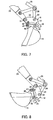
Fig. 5 is a side view of the attaching and detaching device, illustrating the state immediately before engagement. -
Fig. 6 is a side view of the attaching and detaching device, illustrating the state in which the attaching and detaching device is engaged at one end thereof. -
Fig. 7 is a side view of the attaching and detaching device, illustrating the state in which the attaching and detaching device is engaged at both ends thereof. -
Fig. 8 is a side view of the attaching and detaching device, illustrating how a bucket is moved after engagement of the attaching and detaching device. -
Fig. 9 is a flow chart illustrating a procedure controlling the switching of a setting when replacing an attachment by using the attaching and detaching device. -
- 11
- work machine
- 17
- work arm
- 18
- hydraulic quick coupler as an attachment attaching and detaching device
- 19
- bucket as an attachment
- 52
- monitor
- 53
- switch
- 55
- hydraulic operated breaker as an attachment
- 56
- hydraulic operated crusher as an attachment
- 57
- hydraulic operated grappler as an attachment
- 61
- controller
- 62
- attachment hydraulic circuit as an attachment fluid pressure circuit
- Next, the present invention is explained in detail hereunder, referring to an embodiment thereof shown in
Figs. 1 to 9 . - As illustrated in
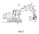
Fig. 2 , awork machine 11 includes alower structure 12, anupper structure 13, acab 14 constituting an operator's cabin, awork equipment 15, and apower system 16 that includes an engine or the like, respectively. Thecab 14, thework equipment 15, and thepower system 16 are mounted on theupper structure 13, which is rotatably mounted on thelower structure 12. The engine drives hydraulic source pumps that serve as a fluid pressure source. Thelower structure 12, theupper structure 13, and thework equipment 15 are adapted to be operated by hydraulic actuators, which are fluid pressure actuators adapted to be driven and controlled by a hydraulic circuit serving as a fluid pressure circuit. - The
work equipment 15 comprises awork arm 17, a hydraulic quick coupler (hereinafter referred to as the quick coupler 18) serving as an attachment attaching and detaching device, and abucket 19. Thebucket 19 is an attachment, i.e. a work tool, and removably attached to the distal end of thework arm 17 via thequick coupler 18. Thework arm 17 includes aboom 22 adapted to be pivoted byboom cylinders 21, and anarm 24 adapted to be pivoted by anarm cylinder 23. Thearm 24 is attached to the distal end of theboom 22 by pin. Thequick coupler 18 is attached to the distal end of thearm 24 and adapted to be pivoted by abucket cylinder 25 and alink plate 26. -
Figs. 3 and4 illustrate an example of thequick coupler 18, wherein the upper part of acoupler body 33 is rotatably coupled to the distal end of thearm 24 and the distal end of thelink plate 26 byshafts portion 34 is formed at one end of the lower part of thecoupler body 33 as an integral part thereof. Formed at the other end of the lower part of thecoupler body 33 is arecess 35, in which a movable engagingportion 36 is disposed. As illustrated inFig. 4 , the distal end of the movable engagingportion 36 is capable of motion, and the base end of the movable engagingportion 36 is attached to thecoupler body 33 by ashaft 37 so that the movable engagingportion 36 is capable of pivoting. - Disposed in the
coupler body 33 is an attaching and detachingcylinder 41, which is pivotally supported at the base end by ashaft 38. The attaching and detachingcylinder 41 has apiston rod 42, which is pivotally coupled at the distal end to the middle part of the movable engagingportion 36 by ashaft 43. Through the directional control of hydraulic oil fed fromhydraulic pumps 44, the attaching and detachingcylinder 41 is switched between a locked position illustrated inFig. 4 , at which the attaching and detachingcylinder 41 is in a non-excited state, and an unlocked position, at which the attaching and detachingcylinder 41 is in an excited state. The aforementioned directional control of the hydraulic oil is performed by means of a solenoid-operateddirectional control valve 45. - The
bucket 19 has abracket 46 provided with twopins Figs. 5 to 6 , the fixed engagingportion 34 of thequick coupler 18 is adapted to catch one of the pins, i.e. thepin 47, from the inside part of thebracket 46. As illustrated inFigs. 6 to 7 , thecoupler body 33 is then pivoted clockwise around thepin 47 so that therecess 35 is fitted over thepin 48. In the state where thecoupler body 33 is in close contact with thebucket 19 as illustrated inFig. 7 , the solenoid-operateddirectional control valve 45 illustrated inFig. 4 is switched to extend thepiston rod 42 of the attaching and detachingcylinder 41 so that the movable engagingportion 36 is pivoted counterclockwise and catches thepin 48 from the inside part of thebracket 46. As a result, thequick coupler 18 and thebucket 19 integrally secured to each other by means of engagement of the fixed engagingportion 34 and the movable engagingportion 36 with the pair ofpins Fig. 8 , extending thebucket cylinder 25 causes thebucket 19, which is integrally secured to thebucket cylinder 25 through thequick coupler 18, to move below thearm 24. -
Fig. 1 illustrates anoperation panel 51 and amonitor 52. Theoperation panel 51 is disposed near an operator's seat (not illustrated) provided in thecab 14. Themonitor 52 normally displays on screen the operating status of the work machine, such as the volume of remaining fuel. Theoperation panel 51 is provided with aswitch 53 for operating thequick coupler 18 mounted on thework arm 17 so that thequick coupler 18 performs attaching and detaching operation. Theswitch 53 has alever 54 adapted to function in such a manner that pulling up thelever 54 and then pushing thelever 54 forward, in other words upward as viewed inFig. 1 , causes the solenoid-operateddirectional control valve 45 illustrated inFig. 4 to be controlled to a locking position and that pulling up thelever 54 and then pulling back thelever 54, in other words downward as viewed inFig. 1 , causes the solenoid-operateddirectional control valve 45 to be controlled to an unlocking position. - In conjunction with switching operation of the
quick coupler 18, themonitor 52 is switched from the default screen displaying the operating status of the work machine to a screen for prompting selection of an attachment. For example, themonitor 52 displays hydraulic attachments, such as a hydraulic operatedbreaker 55, a hydraulic operatedcrusher 56, and a hydraulic operatedgrappler 57, all of which are fluid pressure operated attachments, in addition to thebucket 19, which is not a fluid pressure operated actuator. - Selecting an attachment by the
monitor 52 is done by means of a touch panel or button switches 58 assigned for respective attachments. Themonitor 52 also has a function of a speaker for sounding an emergency alarm by buzzer or providing guidance by voice. - Although the
monitor 52 illustrated inFig. 1 has button switches 58, the manner of selecting an attachment is not limited to operation by such assigned buttons; for example, selection may be made by choosing a hydraulic attachment by means of a selection button unit comprising such as an "up" button and a "down" button, and executing the selection by means of an "enter" button. - A
controller 61 is connected to themonitor 52. An attachmenthydraulic circuit 62 that serves as an attachment fluid pressure circuit for operating the hydraulic attachment is connected to thecontroller 61. - The
controller 61 has a memory device for storing data for changing set conditions of the attachmenthydraulic circuit 62 in accordance with the hydraulic attachment that has been selected. As the memory device of thecontroller 61 includes a memory for storing which hydraulic attachment has been selected, there is no need to repeat the procedure for selecting the hydraulic attachment when restarting the work machine. It is desirable to use a nonvolatile memory as the memory for this purpose, because the nonvolatile memory is capable of retaining the stored information even when power is turned off, unless the stored information is cleared. - The
controller 61 serves to switch settings for the attachmenthydraulic circuit 62 in accordance with the hydraulic attachment that has been selected by using themonitor 52. Examples of settings to be switched include the pressure and flow rate of hydraulic oil to be fed to the hydraulic attachment, as well as the degree of priority with respect to the other actuators, such as theboom cylinders 21, thearm cylinder 23, etc. - Until selection of the attachment is completed, the
controller 61 restrains the functioning of the attachmenthydraulic circuit 62 while retaining the display for urging selection. Thecontroller 61 also has a function of causing a notification signal to be output to urge selection of an attachment until selection is made. - Next, control of the switching of settings by the
controller 61 is explained hereunder, referring to the flow chart illustrated inFig. 9 . - Whether or not the
switch 53 for operating thequick coupler 18 to perform attaching and detaching operation is at the unlocking position is determined. Theswitch 53 is operated by tilting thelever 54 forward or backward after pulling up thelever 54. Therefore, even if thelever 54 is exposed to a force in such a direction as to tilt thelever 54 by an accidental contact or other unintentional force, such a force alone does not shift theswitch 53 to the unlocking position. - If the
switch 53 is not at the unlocking position, it means that an attachment is already attached so that thelever 54 has returned to its default position. Therefore, whether or not operation for selecting an attachment has been carried out is determined. At that time, the screen of themonitor 52 is automatically switched to the attachment display screen illustrated inFig. 1 , in other words to a screen for prompting the operator to select an attachment, in other words designate the attachment mounted, from among a plurality of available attachments, such as, for example, the hydraulic operatedbreaker 55, the hydraulic operatedcrusher 56, the hydraulic operatedgrappler 57, and thebucket 19. - As selecting an attachment can be performed by means of such a component of the
monitor 52 as a touch panel, the button switches 58 assigned for respective attachments, or the aforementioned combination of the selection button unit and the "enter" button, whether or not an attachment has been selected can be determined. - If an attachment has been selected, the display on the
monitor 52 is switched back to the default screen, such as display of the volume of remaining fuel. - In accordance with the attachment that has been selected, hydraulic settings for the attachment
hydraulic circuit 62 are automatically switched. For example, the pressure and flow rate of hydraulic oil to be fed to the hydraulic attachment, as well as the degree of priority with respect to the other actuators, are automatically adjusted. - If it is determined in Step S2 that no attachment has been selected, whether or not a specified period of time has elapsed is determined.
- Should the state continue in which selection of an attachment is not made, until it is determined in Step S5 that the specified period of time has elapsed, a notification signal in the form of a buzzer or voice guidance is output to urge the making of a selection, while the monitor continues to display the prompt for selecting an attachment.
- Throughout the aforementioned period of time, the function of the attachment
hydraulic circuit 62 is reduced by withholding the supply of hydraulic oil to the hydraulic attachment, or limiting the pressure or flow rate of the supplied hydraulic oil to an extremely low level. As a result, when the operator tries to operate the attachment, damage to the hydraulic attachment is prevented, and the operator is readily reminded of the fact that attachment selection has been forgotten. This reduction of the function of the attachmenthydraulic circuit 62 is performed through automatic control, such as, for example, reducing the set pressure of the relief valve of the hydraulic source of the attachmenthydraulic circuit 62, opening a bypass valve, or preventing the spools of a flow control valve from moving. - If it is determined in Step S5 that the specified period of time has elapsed, it is assumed that the attachment is a bucket.
- The display on the monitor is returned to the default screen. To be more specific, in cases where the bucket is replaced with another
bucket 19, which does not require an attachmenthydraulic circuit 62, it is troublesome to perform operation for selecting an attachment on the screen. Therefore, after the specified period of time has elapsed, the display on themonitor 52 for selecting an attachment is returned to the default screen. As the bucket does not require the attachmenthydraulic circuit 62, the process proceeds to Step S7. - If it is determined in Step S1 that the
switch 53 for operating thequick coupler 18 to perform an attaching and detaching operation is at the unlocking position, the current attachment that has been selected is cleared. - Warning is provided by a buzzer or other appropriate means to indicate that the attachment has been detached.
- Next, the operations and effects of the embodiment illustrated in the drawings are explained hereunder.
- Attachments are changed by means of the
quick coupler 18, which is attached to the distal end of thearm 24. - At that time, removal and attachment of an attachment is performed by operating the
switch 53 provided in thecab 14. In conjunction with this operation, available attachments are displayed on themonitor 52 in thecab 14 as illustrated inFig. 1 , and a prompt is given on themonitor 52 to select an attachment. - At that time, upon the operator selecting an attachment by means of the
monitor 52, the attachmenthydraulic circuit 62 is adjusted to the flow rate and the pressure corresponding to those of the attachment that is going to replace the current attachment through thecontroller 61, which is connected to themonitor 52. - In other words, in accordance with the hydraulic attachment, which may be selected from among a hydraulic operated
breaker 55, a hydraulic operatedcrusher 56, and a hydraulic operatedgrappler 57 etc., the set conditions, such as the pressure and the flow rate, of the hydraulic oil fed to the hydraulic attachment is automatically changed by controlling components of the attachmenthydraulic circuit 62, such as pressure control valves (e.g. a relief valve, a pressure reducing valve, etc.) and flow control valves (e.g. a solenoid-operated directional control valve for controlling the pilot pressure of the main spool for the attachment), or the degree of priority over the other actuators is changed according to the hydraulic attachment. - As described above, in conjunction with operation of the
switch 53 for operating thequick coupler 18 so that thequick coupler 18 performs attaching and detaching operation, a prompting screen for selecting, in other words designating, the mounted attachment from among a plurality of available attachments is displayed on themonitor 52 so that the attachment is selected by means of such a component of themonitor 52 as a touch panel, the button switches 58 assigned for the respective available attachments, or the aforementioned combination of the selection button unit and the "enter" button. Thus, selection can be made with a minimal operation, with essentially the same ease as with the conventional automatic selection systems without the need of providing each attachment with identification information. Furthermore, even with an operator who is operating awork machine 11 according to the present invention for the first time, a lapse or an operation mistake is prevented. - In accordance with the hydraulic attachment that has been selected by means of the
monitor 52, thecontroller 61 automatically switches hydraulic settings for the attachmenthydraulic circuit 62 based on conditions set for the respective attachments beforehand. Therefore, a hydraulic pressure and flow rate for the attachmenthydraulic circuit 62 appropriate for each respective hydraulic attachment can reliably be supplied at an appropriate timing. - Until selection of an attachment is completed, the
controller 61 retains the display for urging selection while restraining the functioning of the attachmenthydraulic circuit 62 by withholding the supply of hydraulic oil to the attachmenthydraulic circuit 62 or limiting the pressure or flow rate of the supplied hydraulic oil to an extremely low level. Therefore, even if the operator starts operation without remembering to perform selecting operation, not only is it possible to prevent damage to the hydraulic attachment but also promptly alert the operator to the irregularity, thereby reminding the operator to perform selection. - Moreover, the present invention is capable of achieving these effects without requiring additional parts or components.
- Furthermore, until selection is made, the
controller 61 continues to cause a notification signal in the form of a buzzer or voice guidance to be output in order to urge the making of a selection. By thus preventing the operator from a lapse in carrying out selection operation, selection of an attachment is ensured. With regard to system design of thequick coupler 18, in cases where warning of the unlocked state of an attachment is given in the form of buzzer, it is functionally desirable to give a notification signal in the form of voice guidance so as to prevent any confusion between the two types of warning. - As described above, even if the
work machine 11 is provided with a hydraulicquick coupler 18, the present invention is capable of fully solving the problems with thework machines 11 that are not provided with an automatic identification device as well as problems with conventional automatic identification devices. - The present invention is applicable to a
work machine 11, such as a hydraulic excavator, that is capable of selectively performing work by means of a plurality of attachments.
Claims (3)
- A work machine control device comprising:a switch for operating an attachment attaching and detaching device that is mounted on a work arm and serves to attach or detach a fluid pressure operated attachment;a monitor for displaying a prompting screen for selecting an attachment in conjunction with operation of the switch for operating the attachment attaching and detaching device; anda controller for switching, in accordance with the attachment selected by using the monitor, settings for an attachment fluid pressure circuit that serves to operate the attachment.
- A work machine control device as claimed in claim 1, wherein:the controller is capable of restraining functioning of the attachment fluid pressure circuit until selection of an attachment is made.
- A work machine control device as claimed in claim 1 or claim 2, wherein:the controller is capable of causing a notification signal to be output to urge selection of an attachment until selection of an attachment is made.
Applications Claiming Priority (2)
| Application Number | Priority Date | Filing Date | Title |
|---|---|---|---|
| JP2007110667A JP2008266975A (en) | 2007-04-19 | 2007-04-19 | Control unit of working machine |
| PCT/JP2008/053649 WO2008132874A1 (en) | 2007-04-19 | 2008-02-29 | Control unit for operating machine |
Publications (2)
| Publication Number | Publication Date |
|---|---|
| EP2138639A1 true EP2138639A1 (en) | 2009-12-30 |
| EP2138639A4 EP2138639A4 (en) | 2011-04-20 |
Family
ID=39925342
Family Applications (1)
| Application Number | Title | Priority Date | Filing Date |
|---|---|---|---|
| EP08721069A Withdrawn EP2138639A4 (en) | 2007-04-19 | 2008-02-29 | Control unit for operating machine |
Country Status (5)
| Country | Link |
|---|---|
| US (1) | US20100185335A1 (en) |
| EP (1) | EP2138639A4 (en) |
| JP (1) | JP2008266975A (en) |
| CN (1) | CN101542047A (en) |
| WO (1) | WO2008132874A1 (en) |
Cited By (3)
| Publication number | Priority date | Publication date | Assignee | Title |
|---|---|---|---|---|
| WO2012085500A3 (en) * | 2010-12-21 | 2012-09-27 | Miller International Ltd. | Coupler alarm and instructional guide for an excavator |
| KR20170071546A (en) * | 2014-10-16 | 2017-06-23 | 얀마 가부시키가이샤 | Work vehicle |
| EP2584099A4 (en) * | 2010-06-21 | 2017-11-08 | Caterpillar SARL | Quick coupler circuit for construction equipment |
Families Citing this family (17)
| Publication number | Priority date | Publication date | Assignee | Title |
|---|---|---|---|---|
| JP5740090B2 (en) * | 2010-01-18 | 2015-06-24 | 松山株式会社 | Agricultural machine remote control system |
| JP5363430B2 (en) * | 2010-07-23 | 2013-12-11 | 日立建機株式会社 | Hybrid construction machine |
| CN102351137A (en) * | 2011-10-11 | 2012-02-15 | 中国人民解放军总后勤部建筑工程研究所 | Accessory recognition system for multifunctional off-road forklift trunk |
| CN103321270A (en) * | 2013-06-26 | 2013-09-25 | 合肥振宇工程机械有限公司 | Automatic recognition system and automatic recognition method for switching of multiple working devices of dredger |
| WO2015102120A1 (en) * | 2013-12-30 | 2015-07-09 | 볼보 컨스트럭션 이큅먼트 에이비 | Hydraulic control device and construction equipment having same |
| JP6176666B2 (en) | 2014-04-08 | 2017-08-09 | キャタピラー エス エー アール エル | Control device for quick coupler in work machine |
| KR102394965B1 (en) * | 2014-10-16 | 2022-05-04 | 얀마 파워 테크놀로지 가부시키가이샤 | Work vehicle |
| JP6080830B2 (en) * | 2014-11-05 | 2017-02-15 | ヤンマー株式会社 | Tractor |
| US10281923B2 (en) | 2016-03-03 | 2019-05-07 | Uber Technologies, Inc. | Planar-beam, light detection and ranging system |
| KR102456138B1 (en) * | 2016-09-29 | 2022-10-17 | 스미토모 겐키 가부시키가이샤 | shovel |
| JP2018084286A (en) * | 2016-11-24 | 2018-05-31 | 川崎重工業株式会社 | Manipulating device and hydraulic system |
| US11692329B2 (en) | 2017-01-17 | 2023-07-04 | Doosan Infracore Co., Ltd. | Apparatus for controlling and method for controlling quick-clamping of construction machine |
| KR101994132B1 (en) * | 2017-03-29 | 2019-06-28 | 가부시키가이샤 고마쓰 세이사쿠쇼 | Manipulators of working machines |
| EP3947827A4 (en) * | 2019-03-27 | 2022-11-23 | Volvo Construction Equipment AB | Quick coupler circuit of construction machine with automatic pressurization system |
| JP2019116832A (en) * | 2019-04-11 | 2019-07-18 | 株式会社小松製作所 | Work machine management device |
| US11698086B2 (en) | 2020-12-18 | 2023-07-11 | Cnh Industrial America Llc | Systems and methods to control movement of a work vehicle attachment |
| CN115573410B (en) * | 2022-12-09 | 2023-03-14 | 柳工常州机械有限公司 | Bulldozer and control system thereof |
Citations (3)
| Publication number | Priority date | Publication date | Assignee | Title |
|---|---|---|---|---|
| US4955779A (en) * | 1986-10-28 | 1990-09-11 | Jaromir Vaclav Drazil | Connector |
| EP1239208A2 (en) * | 2001-03-10 | 2002-09-11 | Deere & Company | Electrohydraulic circuit for relieving the pressure of quick-connect couplings |
| EP1752588A1 (en) * | 2004-04-19 | 2007-02-14 | Hitachi Construction Machinery Co., Ltd. | Display device for construction machine |
Family Cites Families (10)
| Publication number | Priority date | Publication date | Assignee | Title |
|---|---|---|---|---|
| JP3210221B2 (en) * | 1995-10-11 | 2001-09-17 | 新キャタピラー三菱株式会社 | Construction machine control circuit |
| JPH11140911A (en) * | 1997-11-06 | 1999-05-25 | Shin Caterpillar Mitsubishi Ltd | Device and method for controlling construction machine |
| JP3323791B2 (en) * | 1997-11-25 | 2002-09-09 | 新キャタピラー三菱株式会社 | Control device and control method for construction machine |
| WO2000037744A1 (en) * | 1998-12-22 | 2000-06-29 | Caterpillar Inc. | Tool recognition and control system for a work machine |
| JP2001323516A (en) * | 2000-05-16 | 2001-11-22 | Shin Caterpillar Mitsubishi Ltd | Working device discrimination system of working machine |
| JP4519315B2 (en) * | 2000-12-28 | 2010-08-04 | 株式会社小松製作所 | Construction equipment pressure oil flow control device |
| KR100892269B1 (en) * | 2001-06-15 | 2009-04-09 | 가부시키가이샤 고마쓰 세이사쿠쇼 | Construction machine |
| US7032703B2 (en) * | 2002-06-17 | 2006-04-25 | Caterpillar Inc. | Operator control station for controlling different work machines |
| US6928353B2 (en) * | 2002-08-01 | 2005-08-09 | Caterpillar Inc. | System and method for providing data to a machine control system |
| US7178623B2 (en) * | 2003-12-19 | 2007-02-20 | Caterpillar Inc | Operator control assembly |
-
2007
- 2007-04-19 JP JP2007110667A patent/JP2008266975A/en active Pending
-
2008
- 2008-02-29 CN CNA200880000257XA patent/CN101542047A/en active Pending
- 2008-02-29 EP EP08721069A patent/EP2138639A4/en not_active Withdrawn
- 2008-02-29 US US12/305,899 patent/US20100185335A1/en not_active Abandoned
- 2008-02-29 WO PCT/JP2008/053649 patent/WO2008132874A1/en active Application Filing
Patent Citations (3)
| Publication number | Priority date | Publication date | Assignee | Title |
|---|---|---|---|---|
| US4955779A (en) * | 1986-10-28 | 1990-09-11 | Jaromir Vaclav Drazil | Connector |
| EP1239208A2 (en) * | 2001-03-10 | 2002-09-11 | Deere & Company | Electrohydraulic circuit for relieving the pressure of quick-connect couplings |
| EP1752588A1 (en) * | 2004-04-19 | 2007-02-14 | Hitachi Construction Machinery Co., Ltd. | Display device for construction machine |
Non-Patent Citations (1)
| Title |
|---|
| See also references of WO2008132874A1 * |
Cited By (9)
| Publication number | Priority date | Publication date | Assignee | Title |
|---|---|---|---|---|
| EP2584099A4 (en) * | 2010-06-21 | 2017-11-08 | Caterpillar SARL | Quick coupler circuit for construction equipment |
| WO2012085500A3 (en) * | 2010-12-21 | 2012-09-27 | Miller International Ltd. | Coupler alarm and instructional guide for an excavator |
| GB2502458A (en) * | 2010-12-21 | 2013-11-27 | Miller Int Ltd | Coupler alarm and instructional guide |
| KR20170071546A (en) * | 2014-10-16 | 2017-06-23 | 얀마 가부시키가이샤 | Work vehicle |
| CN107072144A (en) * | 2014-10-16 | 2017-08-18 | 洋马株式会社 | Working truck |
| EP3207781A4 (en) * | 2014-10-16 | 2017-10-25 | Yanmar Co., Ltd. | Work vehicle |
| US10721856B2 (en) | 2014-10-16 | 2020-07-28 | Yanmar Co., Ltd. | Work vehicle |
| EP3865332A1 (en) * | 2014-10-16 | 2021-08-18 | Yanmar Power Technology Co., Ltd. | Work vehicle |
| US11612094B2 (en) | 2014-10-16 | 2023-03-28 | Yanmar Power Technology Co., Ltd. | Work vehicle |
Also Published As
| Publication number | Publication date |
|---|---|
| JP2008266975A (en) | 2008-11-06 |
| CN101542047A (en) | 2009-09-23 |
| WO2008132874A1 (en) | 2008-11-06 |
| US20100185335A1 (en) | 2010-07-22 |
| EP2138639A4 (en) | 2011-04-20 |
Similar Documents
| Publication | Publication Date | Title |
|---|---|---|
| EP2138639A1 (en) | Control unit for operating machine | |
| JP4079113B2 (en) | Construction machine display device | |
| JP4310632B2 (en) | Construction machine display device | |
| EP1538267B1 (en) | Construction machine with a monitoring display device to observe the space behind the construction machine | |
| US20140212846A1 (en) | Coupler Alarm and Instructional Guide | |
| EP0816579B1 (en) | Control system equipped on a construction machine | |
| KR20020016822A (en) | An operator interface for a skid steer loader | |
| US6212483B1 (en) | Apparatus and method of providing diagnostic information to an operator | |
| EP4306726A1 (en) | Work machine | |
| KR101058463B1 (en) | Display of construction machinery | |
| JP2008266976A (en) | Control unit of working machine | |
| KR20100106466A (en) | Construction machine | |
| JP2006274788A (en) | Safety device of work machine and service system of work machine | |
| CN211113858U (en) | Protection control device and excavator during pilot operation failure | |
| US20230183942A1 (en) | Work Machine Control Method, Work Machine Control Program, Work Machine Control System, And Work Machine | |
| JP4025676B2 (en) | Work machine input device | |
| JP2018053605A (en) | Construction machine | |
| KR100674120B1 (en) | Hang-up equipment for hydraulic excavator | |
| EP3814578B1 (en) | Method and system to securely manage quick coupling of tools in an earth moving equipment | |
| KR20230069858A (en) | Control method of working machine, control program for working machine, control system for working machine and working machine | |
| JP2023074222A (en) | Control method for work machine, control program for work machine, control system for work machine and work machine | |
| JP2023074224A (en) | Control method for work machine, control program for work machine, control system for work machine and work machine | |
| JP2023074223A (en) | Control method for work machine, control program for work machine, control system for work machine and work machine | |
| CN115874665A (en) | Control system for work machine, control method for work machine, and control program for work machine | |
| CN117248592A (en) | Work machine control method, work machine control program, work machine control system, and work machine |
Legal Events
| Date | Code | Title | Description |
|---|---|---|---|
| PUAI | Public reference made under article 153(3) epc to a published international application that has entered the european phase |
Free format text: ORIGINAL CODE: 0009012 |
|
| 17P | Request for examination filed |
Effective date: 20091118 |
|
| AK | Designated contracting states |
Kind code of ref document: A1 Designated state(s): AT BE BG CH CY CZ DE DK EE ES FI FR GB GR HR HU IE IS IT LI LT LU LV MC MT NL NO PL PT RO SE SI SK TR |
|
| DAX | Request for extension of the european patent (deleted) | ||
| RAP1 | Party data changed (applicant data changed or rights of an application transferred) |
Owner name: CATERPILLAR SARL |
|
| A4 | Supplementary search report drawn up and despatched |
Effective date: 20110318 |
|
| 17Q | First examination report despatched |
Effective date: 20111212 |
|
| STAA | Information on the status of an ep patent application or granted ep patent |
Free format text: STATUS: THE APPLICATION IS DEEMED TO BE WITHDRAWN |
|
| 18D | Application deemed to be withdrawn |
Effective date: 20120424 |