EP2138428B1 - Kommissionierungseinheit - Google Patents
Kommissionierungseinheit Download PDFInfo
- Publication number
- EP2138428B1 EP2138428B1 EP09005041A EP09005041A EP2138428B1 EP 2138428 B1 EP2138428 B1 EP 2138428B1 EP 09005041 A EP09005041 A EP 09005041A EP 09005041 A EP09005041 A EP 09005041A EP 2138428 B1 EP2138428 B1 EP 2138428B1
- Authority
- EP
- European Patent Office
- Prior art keywords
- picking
- order
- carriage
- rack
- assembly line
- Prior art date
- Legal status (The legal status is an assumption and is not a legal conclusion. Google has not performed a legal analysis and makes no representation as to the accuracy of the status listed.)
- Active
Links
Images

Classifications
-
- B—PERFORMING OPERATIONS; TRANSPORTING
- B65—CONVEYING; PACKING; STORING; HANDLING THIN OR FILAMENTARY MATERIAL
- B65G—TRANSPORT OR STORAGE DEVICES, e.g. CONVEYORS FOR LOADING OR TIPPING, SHOP CONVEYOR SYSTEMS OR PNEUMATIC TUBE CONVEYORS
- B65G1/00—Storing articles, individually or in orderly arrangement, in warehouses or magazines
- B65G1/02—Storage devices
- B65G1/04—Storage devices mechanical
- B65G1/137—Storage devices mechanical with arrangements or automatic control means for selecting which articles are to be removed
- B65G1/1373—Storage devices mechanical with arrangements or automatic control means for selecting which articles are to be removed for fulfilling orders in warehouses
- B65G1/1375—Storage devices mechanical with arrangements or automatic control means for selecting which articles are to be removed for fulfilling orders in warehouses the orders being assembled on a commissioning stacker-crane or truck
Definitions
- the invention relates to a picking unit according to the preamble of patent claim 1.
- a picking unit is described, which is kept movable on a running part. Also from the JP 63267604 is a mobile order picking known. Furthermore, the shows DE 203 11 674 U1 a picking trolley, which can be pushed by hand and has at least two vertically offset storage compartments, which are slidably mounted in the horizontal direction.
- the US 3,908,800 describes a picking shelf, which is kept movable on rollers.
- the present invention is based on the problem to create a new picking unit.
- This problem is solved by a picking unit according to claim 1.
- the order picking shelf can be removed obliquely from the order picking trolley or placed on the order picking trolley during the transfer of the order picking shelf from the picking trolley to the assembly line and, conversely, when the picking rack is transferred from the assembly line to the picking trolley.
- the present invention proposes a picking unit comprising a picking rack and a picking trolley, in which the transfer of the picking rack between the picking trolley and the assembly line takes place in an oblique direction.
- a picking unit comprising a picking rack and a picking trolley, in which the transfer of the picking rack between the picking trolley and the assembly line takes place in an oblique direction.
- a receptacle of the picking trolley for the order picking shelf has a height which is adapted to the height of a receiving platform of the assembly line for the picking shelf.
- the order picking shelf can then be transferred between the picking trolley and the assembly line without the aid of lifting devices between the assembly line and the picking trolley.
- the invention relates to a picking unit comprising a picking rack and a picking cart.
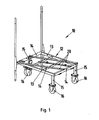
- Fig. 1 to 4 show different views of a picking trolley 10 of a picking unit according to the invention
- Fig. 5 shows a view of a picking shelf 11 of the picking unit according to the invention.
- the picking trolley 10 of the picking unit according to the invention has a receptacle 12 for the order picking shelf 11, the receptacle 12 being formed by side rails 13 and transverse struts 14. On supports 12 of the picking trolley 10 engage on supports 15 rollers 16. About the rollers 16 of the order picking 10 can be moved on a floor of an assembly hall.
- the order picking shelf 11 is in accordance with Fig. 5 formed by a frame in which several drawers 17 are positioned one above the other, which serve to receive items required for assembly.
- the drawers are guided in guide rails 18 which extend on side walls of the picking frame 11.
- the order picking shelf 11 can be positioned on the receptacle 12 of the picking trolley 10.
- the order picking 11 is obliquely removable from the picking 10 and positioned on the same.
- the receptacle 12 of the picking trolley 10 for the order picking shelf 11 and a bottom 19 of the order picking 11 cooperating guide rails 20, 21 are assigned, which extend obliquely to side walls of the order picking shelf 11 and obliquely to the side rails 13 of the picking trolley 10. Via the guide rails 20, 21 it is ensured that the order picking shelf 11 can be displaced obliquely to the picking trolley 10 during removal thereof from the picking trolley 10 or when placing same on the picking trolley 10.
- the height of the receptacle 12 of the picking trolley 10 is adapted to a height of a receiving platform of the assembly line for the picking shelf 11. This can ensure that when transferring the order picking shelf 11 between the assembly line and the order picking 10 no tools such as lifting devices are needed.
- the picking unit according to the invention from the picking trolley 10 and the order picking shelf 11 can be positioned on a driverless transport vehicle and can be moved by the driverless transport vehicle.
- the driverless transport vehicle is inserted under the picking 10 of the picking unit according to the invention, so that the picking 10 optionally together with the order picking shelf 11 is seated on the driverless transport vehicle and can be relocated from the same.
Description
- Die Erfindung betrifft eine Kommissionierungseinheit nach dem Oberbegriff des Patentanspruchs 1.
- In der
EP 1 862 406 A1 ist eine Kommissionierungseinheit beschrieben, die auf einem Fahrteil beweglich gehalten ist. Auch aus derJP 63267604 DE 203 11 674 U1 einen Kommissionierwagen, der von Hand geschoben werden kann und mindestens zwei vertikal versetzte Ablagefächer aufweist, die in horizontaler Richtung verschiebbar gelagert sind. DieUS 3,908,800 beschreibt ein Kommissionierregal, das auf Rollen verfahrbar gehalten ist. - Aus der
DE 102 43 475 A1 sowie derDE 102 43 477 B4 sind Einrichtungen zur Montage von Motoren, nämlich von Brennkraftmaschinen eines Kraftfahrzeugs, bekannt. So weisen die aus diesem Stand der Technik bekannten Einrichtungen zur Montage von Brennkraftmaschinen ein Montageband auf, wobei auf dem Montageband einerseits Montageträger für Brennkraftmaschinen und andererseits als Kommissionierungsregale ausgebildete Kommissionierungseinrichtungen positionierbar sind. Eine auf dem Montageträger positionierte Brennkraftmaschine ist zusammen mit dem Kommissionierungsregal, auf dem zur Montage der Brennkraftmaschine benötigte Einzelteile bereitgehalten werden, zur Montage mit Hilfe des Montagebands durch einzelne Montagestatonen transportierbar. - Nach der Praxis bereitet die Handhabung der Kommissionierungsregale zwischen einer Kommissionierungsstation, in welcher dieselbe mit den benötigten Einzelteilen bestückt werden, und dem Montageband Schwierigkeiten. So ist es zwar bekannt, Kommissionierungsregale mit Hilfe von Kommissionierungswagen zwischen der Kommissionierungsstation und dem Montageband hin- und her zu transportieren, dass Positionieren der Kommissionierungsregale auf dem Kommissionierungswagen sowie das Posttionieren der Kommissionierungsregale auf dem Montageband ist jedoch bislang umständlich.
- Hiervon ausgehend liegt der vorliegenden Erfindung das Problem zu Grunde eine neuartige Kommissionierungseinheit zu schaffen. Dieses Problem wird durch eine Kommissionierungseinheit gemäß Patentanspruch 1 gelöst. Erfindungsgemäß ist bei der Übergabe des Kommissionierungsregals vom Kommissionierungswagen an das Montageband sowie umgekehrt bei der Übergabe des Kommissionierungsregals vom Montageband an den Kommissionierungswagen das Kommissionierungsregal schräg vom Kommissionierungswagen entfernbar bzw. auf demselben platzierbar.
- Die hier vorliegende Erfindung schlägt eine Kommissionierungseinheit aus einem Kommissionierungsregal und einem Kommissionierungswagen vor, bei welchem die Übergabe des Kommissionierungsregals zwischen dem Kommissionierungswagen und dem Montageband in einer schräg verlaufenden Richtung erfolgt. Eine solche schräge Übergabe des Kommissionierungsregals zwischen dem Kommissionierungswagen und der Montagestation erlaubt selbst dann eine problemlose Handhabung der Kommissionierungsregale im Bereich des Montagebands, wenn an einem Montageträger des Montagebands Motoren mit großen Abmessungen aufgenommen werden.
- Vorzugsweise weist eine Aufnahme des Kommissionierungswagens für das Kommissionierungsregal eine Höhe auf, die an die Höhe einer Aufnahmeplattform des Montagebands für das Kommissionierungsregal angepasst ist. In diesem Fall kann dann das Kommissionierungsregal zwischen dem Kommissionierungswagen und dem Montageband ohne Zuhilfenahme von Hubeinrichtungen zwischen dem Montageband und dem Kommissionierungswagen übergeben werden.
- Bevorzugte Weiterbildungen der Erfindung ergeben sich aus den Unteransprüchen und der nachfolgenden Beschreibung. Ausführungsbeispiele der Erfindung werden, ohne hierauf beschränkt zu sein, an Hand der Zeichnung näher erläutert. Dabei zeigt:
- Fig. 1
- eine perspektivische Ansicht eines Kommissionierungswagens einer erfin- dungsgemäßen Kommissionierungseinheit;
- Fig. 2
- den Kommissionierungswagen der
Fig. 1 in Seitenansicht; - Fig. 3
- den Kommissionierungswagen der
Fig. 1 in Vorderansicht; - Fig. 4
- den Kommissionierungswagen der
Fig. 1 in Draufsicht; und - Fig. 5
- eine perspektivische Ansicht eines Kommissionierungsregals einer erfin- dungsgemäßen Kommissionierungseinheit.
- Die Erfindung betrifft eine Kommissionierungseinheit, die ein Kommissionierungsregal und einen Kommissionierungswagen umfasst.
Fig. 1 bis 4 zeigen unterschiedliche Ansichten eines Kommissionierungswagens 10 einer erfindungsgemäßen Kommissionierungseinheit,Fig. 5 zeigt eine Ansicht eines Kommissionierungsregals 11 der erfindungsgemäßen Kommissionierungseinheit. - Der Kommissionierungswagen 10 der erfindungsgemäßen Kommissionierungseinheit verfügt über eine Aufnahme 12 für das Kommissionierungsregal 11, wobei die Aufnahme 12 von Seitenholmen 13 und Querholmen 14 gebildet ist. An der Aufnahme 12 des Kommissionierungswagens 10 greifen über Stützen 15 Laufrollen 16 an. Über die Laufrollen 16 kann der Kommissionierungswagen 10 auf einem Boden einer Montagehalle verfahren werden.
- Das Kommissionierungsregal 11 wird gemäß
Fig. 5 von einem Rahmen gebildet, in dem übereinander mehrere Schubladen 17 positioniert sind, die der Aufnahme von zur Montage benötigten Einzelteilen dienen. Die Schubladen sind in Führungsschienen 18 geführt, die sich an Seitenwänden des Kommissionierungsrahmens 11 erstrecken. - Das Kommissionierungsregal 11 ist auf der Aufnahme 12 des Kommissionierungswagens 10 positionierbar. Bei der Übergabe des Kommissionierungsregals 11 vom Kommissionierungswagen 10 an ein nicht gezeigtes Montageband sowie umgekehrt bei der Übergabe des Kommissionierungsregals 11 vom Montageband an den Kommissionierungswagen 10 ist das Kommissionierungsregal 11 schräg vom Kommissionierungswagen 10 entfernbar bzw. auf demselben positionierbar.
- Hierzu sind der Aufnahme 12 des Kommissionierungswagens 10 für das Kommissionierungsregal 11 und einem Boden 19 des Kommissionierungsregals 11 zusammenwirkende Führungsschienen 20, 21 zugeordnet, die sich schräg zu Seitenwänden des Kommissionierungsregals 11 sowie schräg zu den Seitenholmen 13 des Kommissionierungswagens 10 erstrecken. Über die Führungsschienen 20, 21 wird gewährleistet, dass das Kommissionierungsregal 11 schräg zum Kommissionierungswagen 10 beim Entfernen desselben vom Kommissionierungswagen 10 bzw. beim Platzieren desselben auf dem Kommissionierungswagen 10 verlagert werden kann.
- Die Höhe der Aufnahme 12 des Kommissionierungswagens 10 ist an eine Höhe einer Aufnahmeplattform des Montagebands für das Kommissionierungsregal 11 angepasst. Hierdurch kann gewährleistet werden, dass bei der Übergabe des Kommissionierungsregals 11 zwischen dem Montageband und dem Kommissionierungswagen 10 keine Hilfsmittel wie Hubeinrichtungen benötigt werden.
- Die erfindungsgemäße Kommissionierungseinheit aus dem Kommissionierungswagen 10 und dem Kommissionierungsregal 11 ist auf einem führerlosen Transportfahrzeug positionierbar und vom dem führerlosen Transportfahrzeug verlagerbar. Hierzu ist das führerlose Transportfahrzeug unter den Kommissionierungswagen 10 der erfindungsgemäßen Kommissionierungseinheit einführbar, sodass der Kommissionierungswagen 10 gegebenenfalls zusammen mit dem Kommissionierungsregal 11 auf dem führerlosen Transportfahrzeug aufsitzt und von demselben verlagert werden kann.
Claims (4)
- Kommissionierungseinheit mit einem Kommissionierungsregal, auf dem zur Montage einer zu montierende Einheit, insbesondere eines zu montierenden Motors, benötigte Einzelteilen bereitgehalten werden, und mit einem Kommissionierungswagen, auf dem das Kommissionierungsregal zum Transport desselben zwischen einer Kommissionierungsstation und einem Montageband positionierbar, wobei
bei der Übergabe des Kommissionierungsregals (11) vom Kommissionierungswagen (10) an das Montageband sowie umgekehrt bei der Übergabe des Kommissionierungsregals (11) vom Montageband an den Kommissionierungswagen (10) das Kommissionierungsregal (11) schräg vom Kommissionierungswagen (10) entfernbar bzw. auf demselben platzierbar ist, dadurch gekennzeichnet, dass einer Aufnahme (12) des Kommissionierungswagens (10) für das Kommissionierungsregal (11) und einem Boden (19) des Kommissionierungsregals (11) zusammenwirkende Führungsschienen (20, 21) zugeordnet sind, die sich schräg zu Seitenwänden des Kommissionierungsregals (11) sowie schräg zu Seitenholmen des Kommissionierungswagens (10) erstrecken. - Kommissionierungseinheit nach Anspruch 1, dadurch gekennzeichnet, dass die Aufnahme (12) des Kommissionierungswagens (10) eine Höhe aufweist, die an die Höhe einer Aufnahmeplattform des Montagebands für das Kommissionierungsregal (11) angepasst ist.
- Kommissionierungseinheit nach einem der Ansprüche 1 bis 2, dadurch gekennzeichnet, dass dieselbe auf einem führerlosen Transportfahrzeug positionierbar und vom führerlosen Transportfahrzeug verlagerbar ist.
- Kommissionierungseinheit nach Anspruch 3, dadurch gekennzeichnet, dass das führerlose Transportfahrzeug unter den Kommissionierungswagen einführbar ist, so dass der Kommissionierungswagen zusammen mit dem Kommissionierungsregal (11) auf dem führerlosen Transportfahrzeug aufsitzt.
Priority Applications (1)
| Application Number | Priority Date | Filing Date | Title |
|---|---|---|---|
| PL09005041T PL2138428T3 (pl) | 2008-06-28 | 2009-04-06 | Jednostka komisjonowania |
Applications Claiming Priority (1)
| Application Number | Priority Date | Filing Date | Title |
|---|---|---|---|
| DE102008030812A DE102008030812A1 (de) | 2008-06-28 | 2008-06-28 | Kommissionierungseinheit |
Publications (2)
| Publication Number | Publication Date |
|---|---|
| EP2138428A1 EP2138428A1 (de) | 2009-12-30 |
| EP2138428B1 true EP2138428B1 (de) | 2012-03-28 |
Family
ID=41138857
Family Applications (1)
| Application Number | Title | Priority Date | Filing Date |
|---|---|---|---|
| EP09005041A Active EP2138428B1 (de) | 2008-06-28 | 2009-04-06 | Kommissionierungseinheit |
Country Status (4)
| Country | Link |
|---|---|
| EP (1) | EP2138428B1 (de) |
| AT (1) | ATE551278T1 (de) |
| DE (1) | DE102008030812A1 (de) |
| PL (1) | PL2138428T3 (de) |
Families Citing this family (3)
| Publication number | Priority date | Publication date | Assignee | Title |
|---|---|---|---|---|
| DE102010040152A1 (de) | 2010-09-02 | 2012-03-08 | Zf Friedrichshafen Ag | Vorrichtung zum Umsetzen von Ladungsträgern und Beladestation |
| DE102011001058A1 (de) | 2011-03-03 | 2012-09-06 | Dr. Ing. H.C. F. Porsche Aktiengesellschaft | Montageeinrichtung sowie Kommissionierungseinheit |
| FR3038243B1 (fr) * | 2015-07-01 | 2017-07-28 | Peugeot Citroen Automobiles Sa | Panier d’approvisionnement en pieces |
Family Cites Families (6)
| Publication number | Priority date | Publication date | Assignee | Title |
|---|---|---|---|---|
| US3908800A (en) * | 1974-04-12 | 1975-09-30 | Scope Inc | Item selecting system |
| JPS63267604A (ja) * | 1987-04-27 | 1988-11-04 | Nippon Filing Co Ltd | ピツキング装置 |
| DE10243475A1 (de) | 2002-09-19 | 2004-04-01 | Dr.Ing.H.C. F. Porsche Ag | Einrichtung zur Montage von Geräten, vorzugsweise Brennkraftmaschinen |
| DE10243477B4 (de) | 2002-09-19 | 2006-09-28 | Dr.Ing.H.C. F. Porsche Ag | Einrichtung zur Montage von Brennkraftmaschinen |
| DE20311674U1 (de) * | 2003-07-28 | 2003-10-02 | Still Wagner Gmbh & Co Kg | Handgeschobener Kommissionierwagen |
| DE102006025934A1 (de) * | 2006-06-02 | 2007-12-06 | Dematic Gmbh & Co. Kg | Verfahren zum Kommissionieren von Artikeln in einem Kommissioniersystem und eine Zwischenlagervorrichtung mit Aufnahmeplätzen |
-
2008
- 2008-06-28 DE DE102008030812A patent/DE102008030812A1/de not_active Withdrawn
-
2009
- 2009-04-06 EP EP09005041A patent/EP2138428B1/de active Active
- 2009-04-06 PL PL09005041T patent/PL2138428T3/pl unknown
- 2009-04-06 AT AT09005041T patent/ATE551278T1/de active
Also Published As
| Publication number | Publication date |
|---|---|
| DE102008030812A1 (de) | 2010-01-07 |
| PL2138428T3 (pl) | 2012-08-31 |
| EP2138428A1 (de) | 2009-12-30 |
| ATE551278T1 (de) | 2012-04-15 |
Similar Documents
| Publication | Publication Date | Title |
|---|---|---|
| DE102011012424B4 (de) | Lager- und Kommissioniersystem mit Shuttle | |
| EP2130789B1 (de) | Anlage zum Be- und Entladen von Hochregalen mit hängender Ware | |
| DE102009026386A1 (de) | Halbautomatisches Kommissioniersystem | |
| AT512338A1 (de) | Kommissionierstation und verfahren zum kommissionieren von artikeln | |
| DE112009001363T5 (de) | Gerät und Verfahren, die eingesetzt werden, um Pakete in einem automatisierten Lager aufzuladen, zu bewegen und abzulegen | |
| DE102009032406A1 (de) | Regallagersystem und Verfahren zum Betreiben eines Regallagersystems | |
| EP2753558B1 (de) | Kommissionierstation und verfahren zum kommissionieren von artikeln aus ladehilfsmitteln | |
| EP1136394A2 (de) | Kommissioniervorrichtung | |
| DE102007018244A1 (de) | Vertikallift und Verfahren zum Betreiben eines Regals mit Vertikallift | |
| DE102015015127A1 (de) | Vorrichtung und Verfahren zum Kommissionieren von Ladungsträgern | |
| WO2015039818A1 (de) | Kommissionieranlage mit pufferschalen aufweisenden regaleinheiten zum kommissionieren auf ein zentralband | |
| EP2138428B1 (de) | Kommissionierungseinheit | |
| EP1862406B1 (de) | Zwischenlagervorrichtung mit Aufnahmeplätzen | |
| EP2354045A1 (de) | Regallager | |
| EP2452900B1 (de) | Rollcontainer-Beladestation, Kommissioniervorrichtung mit einer solchen Station und entsprechende Verfahren | |
| EP1621483A1 (de) | Vorrichtung zum Kommissionieren von Waren in einem Warenlager | |
| DE202005013672U1 (de) | Be- und Entladevorrichtung für ein Regalfahrzeug | |
| EP2714551B1 (de) | Verfahren zum transport von liegewaren und hängewaren und entsprechendes automatisiertes lagersystem | |
| EP3214021B1 (de) | Verfahren zum betreiben eines wabenlagers | |
| EP1862405B1 (de) | Verfahren zum Greifen eines Stückgutes mittels Greifelementen einer Ein- und Auslagervorrichtung und Vorrichtung hierfür | |
| EP4052962B1 (de) | Lageranordnung | |
| DE19723220A1 (de) | Ein- und Auslagerungsvorrichtung für ein Hochregal | |
| DE2540252A1 (de) | Einrichtung zum lagern von palettierten, sowie flaechen- und stabfoermigen teilen | |
| EP3388370B1 (de) | Verwendung eines speichers für bauteilträgerwagen | |
| WO2004000697A1 (de) | Verfahren und gerät zum bedienen eines regals vorzugsweise in einer kommissionieranlage |
Legal Events
| Date | Code | Title | Description |
|---|---|---|---|
| PUAI | Public reference made under article 153(3) epc to a published international application that has entered the european phase |
Free format text: ORIGINAL CODE: 0009012 |
|
| AK | Designated contracting states |
Kind code of ref document: A1 Designated state(s): AT BE BG CH CY CZ DE DK EE ES FI FR GB GR HR HU IE IS IT LI LT LU LV MC MK MT NL NO PL PT RO SE SI SK TR |
|
| RAP1 | Party data changed (applicant data changed or rights of an application transferred) |
Owner name: DR. ING. H.C. F. PORSCHE AG |
|
| 17P | Request for examination filed |
Effective date: 20100630 |
|
| 17Q | First examination report despatched |
Effective date: 20100908 |
|
| GRAP | Despatch of communication of intention to grant a patent |
Free format text: ORIGINAL CODE: EPIDOSNIGR1 |
|
| GRAS | Grant fee paid |
Free format text: ORIGINAL CODE: EPIDOSNIGR3 |
|
| GRAA | (expected) grant |
Free format text: ORIGINAL CODE: 0009210 |
|
| AK | Designated contracting states |
Kind code of ref document: B1 Designated state(s): AT BE BG CH CY CZ DE DK EE ES FI FR GB GR HR HU IE IS IT LI LT LU LV MC MK MT NL NO PL PT RO SE SI SK TR |
|
| REG | Reference to a national code |
Ref country code: GB Ref legal event code: FG4D Free format text: NOT ENGLISH |
|
| REG | Reference to a national code |
Ref country code: CH Ref legal event code: EP |
|
| REG | Reference to a national code |
Ref country code: AT Ref legal event code: REF Ref document number: 551278 Country of ref document: AT Kind code of ref document: T Effective date: 20120415 |
|
| REG | Reference to a national code |
Ref country code: IE Ref legal event code: FG4D Free format text: LANGUAGE OF EP DOCUMENT: GERMAN |
|
| REG | Reference to a national code |
Ref country code: DE Ref legal event code: R096 Ref document number: 502009003115 Country of ref document: DE Effective date: 20120524 |
|
| REG | Reference to a national code |
Ref country code: SK Ref legal event code: T3 Ref document number: E 11570 Country of ref document: SK |
|
| REG | Reference to a national code |
Ref country code: NL Ref legal event code: VDEP Effective date: 20120328 |
|
| PG25 | Lapsed in a contracting state [announced via postgrant information from national office to epo] |
Ref country code: NO Free format text: LAPSE BECAUSE OF FAILURE TO SUBMIT A TRANSLATION OF THE DESCRIPTION OR TO PAY THE FEE WITHIN THE PRESCRIBED TIME-LIMIT Effective date: 20120628 Ref country code: LT Free format text: LAPSE BECAUSE OF FAILURE TO SUBMIT A TRANSLATION OF THE DESCRIPTION OR TO PAY THE FEE WITHIN THE PRESCRIBED TIME-LIMIT Effective date: 20120328 Ref country code: HR Free format text: LAPSE BECAUSE OF FAILURE TO SUBMIT A TRANSLATION OF THE DESCRIPTION OR TO PAY THE FEE WITHIN THE PRESCRIBED TIME-LIMIT Effective date: 20120328 |
|
| LTIE | Lt: invalidation of european patent or patent extension |
Effective date: 20120328 |
|
| PG25 | Lapsed in a contracting state [announced via postgrant information from national office to epo] |
Ref country code: LV Free format text: LAPSE BECAUSE OF FAILURE TO SUBMIT A TRANSLATION OF THE DESCRIPTION OR TO PAY THE FEE WITHIN THE PRESCRIBED TIME-LIMIT Effective date: 20120328 Ref country code: FI Free format text: LAPSE BECAUSE OF FAILURE TO SUBMIT A TRANSLATION OF THE DESCRIPTION OR TO PAY THE FEE WITHIN THE PRESCRIBED TIME-LIMIT Effective date: 20120328 Ref country code: GR Free format text: LAPSE BECAUSE OF FAILURE TO SUBMIT A TRANSLATION OF THE DESCRIPTION OR TO PAY THE FEE WITHIN THE PRESCRIBED TIME-LIMIT Effective date: 20120629 |
|
| REG | Reference to a national code |
Ref country code: PL Ref legal event code: T3 |
|
| PG25 | Lapsed in a contracting state [announced via postgrant information from national office to epo] |
Ref country code: CY Free format text: LAPSE BECAUSE OF FAILURE TO SUBMIT A TRANSLATION OF THE DESCRIPTION OR TO PAY THE FEE WITHIN THE PRESCRIBED TIME-LIMIT Effective date: 20120328 |
|
| BERE | Be: lapsed |
Owner name: DR. ING. H.C. F. PORSCHE A.G. Effective date: 20120430 |
|
| PG25 | Lapsed in a contracting state [announced via postgrant information from national office to epo] |
Ref country code: SI Free format text: LAPSE BECAUSE OF FAILURE TO SUBMIT A TRANSLATION OF THE DESCRIPTION OR TO PAY THE FEE WITHIN THE PRESCRIBED TIME-LIMIT Effective date: 20120328 Ref country code: EE Free format text: LAPSE BECAUSE OF FAILURE TO SUBMIT A TRANSLATION OF THE DESCRIPTION OR TO PAY THE FEE WITHIN THE PRESCRIBED TIME-LIMIT Effective date: 20120328 Ref country code: IS Free format text: LAPSE BECAUSE OF FAILURE TO SUBMIT A TRANSLATION OF THE DESCRIPTION OR TO PAY THE FEE WITHIN THE PRESCRIBED TIME-LIMIT Effective date: 20120728 Ref country code: RO Free format text: LAPSE BECAUSE OF FAILURE TO SUBMIT A TRANSLATION OF THE DESCRIPTION OR TO PAY THE FEE WITHIN THE PRESCRIBED TIME-LIMIT Effective date: 20120328 Ref country code: SE Free format text: LAPSE BECAUSE OF FAILURE TO SUBMIT A TRANSLATION OF THE DESCRIPTION OR TO PAY THE FEE WITHIN THE PRESCRIBED TIME-LIMIT Effective date: 20120328 |
|
| PG25 | Lapsed in a contracting state [announced via postgrant information from national office to epo] |
Ref country code: PT Free format text: LAPSE BECAUSE OF FAILURE TO SUBMIT A TRANSLATION OF THE DESCRIPTION OR TO PAY THE FEE WITHIN THE PRESCRIBED TIME-LIMIT Effective date: 20120730 Ref country code: MC Free format text: LAPSE BECAUSE OF NON-PAYMENT OF DUE FEES Effective date: 20120430 |
|
| REG | Reference to a national code |
Ref country code: HU Ref legal event code: AG4A Ref document number: E014506 Country of ref document: HU |
|
| REG | Reference to a national code |
Ref country code: IE Ref legal event code: MM4A |
|
| PG25 | Lapsed in a contracting state [announced via postgrant information from national office to epo] |
Ref country code: NL Free format text: LAPSE BECAUSE OF FAILURE TO SUBMIT A TRANSLATION OF THE DESCRIPTION OR TO PAY THE FEE WITHIN THE PRESCRIBED TIME-LIMIT Effective date: 20120328 Ref country code: DK Free format text: LAPSE BECAUSE OF FAILURE TO SUBMIT A TRANSLATION OF THE DESCRIPTION OR TO PAY THE FEE WITHIN THE PRESCRIBED TIME-LIMIT Effective date: 20120328 Ref country code: BE Free format text: LAPSE BECAUSE OF NON-PAYMENT OF DUE FEES Effective date: 20120430 Ref country code: IE Free format text: LAPSE BECAUSE OF NON-PAYMENT OF DUE FEES Effective date: 20120406 |
|
| PLBE | No opposition filed within time limit |
Free format text: ORIGINAL CODE: 0009261 |
|
| STAA | Information on the status of an ep patent application or granted ep patent |
Free format text: STATUS: NO OPPOSITION FILED WITHIN TIME LIMIT |
|
| PG25 | Lapsed in a contracting state [announced via postgrant information from national office to epo] |
Ref country code: IT Free format text: LAPSE BECAUSE OF FAILURE TO SUBMIT A TRANSLATION OF THE DESCRIPTION OR TO PAY THE FEE WITHIN THE PRESCRIBED TIME-LIMIT Effective date: 20120328 Ref country code: MK Free format text: LAPSE BECAUSE OF FAILURE TO SUBMIT A TRANSLATION OF THE DESCRIPTION OR TO PAY THE FEE WITHIN THE PRESCRIBED TIME-LIMIT Effective date: 20120328 |
|
| 26N | No opposition filed |
Effective date: 20130103 |
|
| REG | Reference to a national code |
Ref country code: FR Ref legal event code: ST Effective date: 20130204 |
|
| REG | Reference to a national code |
Ref country code: DE Ref legal event code: R097 Ref document number: 502009003115 Country of ref document: DE Effective date: 20130103 |
|
| PG25 | Lapsed in a contracting state [announced via postgrant information from national office to epo] |
Ref country code: ES Free format text: LAPSE BECAUSE OF FAILURE TO SUBMIT A TRANSLATION OF THE DESCRIPTION OR TO PAY THE FEE WITHIN THE PRESCRIBED TIME-LIMIT Effective date: 20120709 Ref country code: FR Free format text: LAPSE BECAUSE OF NON-PAYMENT OF DUE FEES Effective date: 20120529 |
|
| PG25 | Lapsed in a contracting state [announced via postgrant information from national office to epo] |
Ref country code: BG Free format text: LAPSE BECAUSE OF FAILURE TO SUBMIT A TRANSLATION OF THE DESCRIPTION OR TO PAY THE FEE WITHIN THE PRESCRIBED TIME-LIMIT Effective date: 20120628 Ref country code: MT Free format text: LAPSE BECAUSE OF FAILURE TO SUBMIT A TRANSLATION OF THE DESCRIPTION OR TO PAY THE FEE WITHIN THE PRESCRIBED TIME-LIMIT Effective date: 20120328 |
|
| REG | Reference to a national code |
Ref country code: CH Ref legal event code: PL |
|
| GBPC | Gb: european patent ceased through non-payment of renewal fee |
Effective date: 20130406 |
|
| PG25 | Lapsed in a contracting state [announced via postgrant information from national office to epo] |
Ref country code: CH Free format text: LAPSE BECAUSE OF NON-PAYMENT OF DUE FEES Effective date: 20130430 Ref country code: GB Free format text: LAPSE BECAUSE OF NON-PAYMENT OF DUE FEES Effective date: 20130406 Ref country code: LI Free format text: LAPSE BECAUSE OF NON-PAYMENT OF DUE FEES Effective date: 20130430 |
|
| PG25 | Lapsed in a contracting state [announced via postgrant information from national office to epo] |
Ref country code: TR Free format text: LAPSE BECAUSE OF FAILURE TO SUBMIT A TRANSLATION OF THE DESCRIPTION OR TO PAY THE FEE WITHIN THE PRESCRIBED TIME-LIMIT Effective date: 20120328 |
|
| PG25 | Lapsed in a contracting state [announced via postgrant information from national office to epo] |
Ref country code: LU Free format text: LAPSE BECAUSE OF NON-PAYMENT OF DUE FEES Effective date: 20120406 |
|
| PGFP | Annual fee paid to national office [announced via postgrant information from national office to epo] |
Ref country code: PL Payment date: 20200327 Year of fee payment: 12 |
|
| PGFP | Annual fee paid to national office [announced via postgrant information from national office to epo] |
Ref country code: AT Payment date: 20200421 Year of fee payment: 12 |
|
| PGFP | Annual fee paid to national office [announced via postgrant information from national office to epo] |
Ref country code: CZ Payment date: 20210406 Year of fee payment: 13 Ref country code: SK Payment date: 20210401 Year of fee payment: 13 |
|
| PGFP | Annual fee paid to national office [announced via postgrant information from national office to epo] |
Ref country code: HU Payment date: 20210516 Year of fee payment: 13 |
|
| REG | Reference to a national code |
Ref country code: AT Ref legal event code: MM01 Ref document number: 551278 Country of ref document: AT Kind code of ref document: T Effective date: 20210406 |
|
| PG25 | Lapsed in a contracting state [announced via postgrant information from national office to epo] |
Ref country code: AT Free format text: LAPSE BECAUSE OF NON-PAYMENT OF DUE FEES Effective date: 20210406 |
|
| PG25 | Lapsed in a contracting state [announced via postgrant information from national office to epo] |
Ref country code: CZ Free format text: LAPSE BECAUSE OF NON-PAYMENT OF DUE FEES Effective date: 20220406 |
|
| REG | Reference to a national code |
Ref country code: SK Ref legal event code: MM4A Ref document number: E 11570 Country of ref document: SK Effective date: 20220406 |
|
| PG25 | Lapsed in a contracting state [announced via postgrant information from national office to epo] |
Ref country code: SK Free format text: LAPSE BECAUSE OF NON-PAYMENT OF DUE FEES Effective date: 20220406 Ref country code: HU Free format text: LAPSE BECAUSE OF NON-PAYMENT OF DUE FEES Effective date: 20220407 |
|
| PG25 | Lapsed in a contracting state [announced via postgrant information from national office to epo] |
Ref country code: PL Free format text: LAPSE BECAUSE OF NON-PAYMENT OF DUE FEES Effective date: 20210406 |
|
| PGFP | Annual fee paid to national office [announced via postgrant information from national office to epo] |
Ref country code: DE Payment date: 20230419 Year of fee payment: 15 |