EP2138268A2 - Einrichtung zum Absondern gasartiger Bestandteile, insbesondere von Luft, aus flüssigen Betriebsmedien - Google Patents
Einrichtung zum Absondern gasartiger Bestandteile, insbesondere von Luft, aus flüssigen Betriebsmedien Download PDFInfo
- Publication number
- EP2138268A2 EP2138268A2 EP09008191A EP09008191A EP2138268A2 EP 2138268 A2 EP2138268 A2 EP 2138268A2 EP 09008191 A EP09008191 A EP 09008191A EP 09008191 A EP09008191 A EP 09008191A EP 2138268 A2 EP2138268 A2 EP 2138268A2
- Authority
- EP
- European Patent Office
- Prior art keywords
- tank
- chamber
- air
- outlet
- media
- Prior art date
- Legal status (The legal status is an assumption and is not a legal conclusion. Google has not performed a legal analysis and makes no representation as to the accuracy of the status listed.)
- Granted
Links
Images

Classifications
-
- B—PERFORMING OPERATIONS; TRANSPORTING
- B01—PHYSICAL OR CHEMICAL PROCESSES OR APPARATUS IN GENERAL
- B01D—SEPARATION
- B01D19/00—Degasification of liquids
- B01D19/0063—Regulation, control including valves and floats
-
- B—PERFORMING OPERATIONS; TRANSPORTING
- B01—PHYSICAL OR CHEMICAL PROCESSES OR APPARATUS IN GENERAL
- B01D—SEPARATION
- B01D19/00—Degasification of liquids
- B01D19/0042—Degasification of liquids modifying the liquid flow
Definitions
- the invention relates to a device for separating gaseous components, in particular of air, from liquid operating media in fluid systems, with a conduit system comprising a storage tank and a conveyor for discharging degassed operating medium from the tank and for returning gaseous constituents containing media mixture to the tank a separator which can be flowed through by the media mixture supplied to the tank causes degassing.
- the invention has for its object to provide a device for separating gaseous components, such as air, from liquids available, which is characterized by a particularly simple structure.
- the separation device causing the degassing has a chamber at the bottom of which the degassed medium accumulates, a significant feature being that the bottom of the chamber has an outlet connected to the tank via a siphon is, which opens up the possibility of maintaining a desired level degassing medium by means of the siphon within the chamber.
- this results in a self-control for the return degassed medium to the tank by by returning the height level of the outlet end of the siphon relative to the level height of the bottom outlet of the chamber, a return of medium into the tank only in response to the fact that the level in the chamber corresponds to the height level of the outlet of the siphon.
- the medium volume permanently present within the siphon also forms a liquid seal between the tank and the separator, which isolates the gas-loaded side of the system from the pure media side.
- the arrangement may be such that the chamber has an inlet for the mixed medium at its upper region opposite the outlet and that the vertical extent of the chamber is chosen such that between the level of the degassed medium and the inlet for the inflowing medium mixture, a calming area for the separation of air is formed. Thanks to the maximum level of accumulated medium in the chamber defined by the siphon, even with changing flow rates it is ensured that the vertical extent of the calming zone maintains the chosen length suitable for the separation of the medium mixture, for example for the separation of air.
- a vent opening is preferably present at the upper end of the chamber.
- the vent opening is provided in a arranged at the upper end of the chamber chamber lid, on which a filter device is arranged, which is traversed by the air, which exits via the vent opening.
- the arrangement may be such that a coarse filter device is present directly on the chamber lid, which also serves as a splash guard.
- this first filter means a fine separation of liquid and exiting air causing second filter device is provided, the clean side forms an air outlet to the environment.
- the device with its line system can be part of the cooling system of a machine installation.
- the cooling liquid for example water with additions of antifreeze and anticorrosive concentrate, at certain Make contact with the outside air, whereby air bubbles are entrained with the cooling liquid.
- This may, for example, relate to a machine tool, in particular in the form of a rotor cooling system used in this regard.
- the device according to the invention not only ensures safe degassing of the cooling fluid but also a particularly environmentally friendly delivery of the exhaust air to the environment.
- such a machine system includes a sealing system, for example as part of a bearing assembly which is supplied with air during operation
- the arrangement may preferably be made in the invention that in the flow path downstream of the second filter device, which forms a fine filter in front of the air outlet to the environment , A connection is provided, via the sealing air, which emerges from the sealing system, the second filter device can be fed. This ensures that it is also avoided by means of the device according to the invention that uncleaned sealing air can escape to the environment, which should be avoided because sealing air can be contaminated with operating media, for example in the ratio of about 100: 1. Such a drainage system is thus advantageous realized for machine tools and comparable machinery.
- the arrangement is such that the chamber is mounted on the tank so that it extends with its bottom outlet through the tank ceiling into the interior of the tank. This results in a very compact construction, in which the siphon is contained directly inside the tank.
- cooling system for. B. pump of the conveyor, heat exchanger, Display and monitoring devices, connection devices and / or the like, mounted on the tank and combined with this to form a unit.
- a uniform cooling unit is formed, which can be connected from its own, suitable location via connecting lines with a respective assigned Maschinenstrom.
- Fig. 1 is designated as a whole with 1 and is provided in practical use for cooling a machine tool. More specifically, it is the rotor cooling and the stator cooling of the machine tool, wherein from the rotor warm, charged with air inclusions return coolant occurs via a terminal 3 in the unit 1.
- This mixed media (cooling liquid with air inclusions) passes through a separator 5 before it enters a compensation or storage tank 7. From the warm side of the stator returning coolant, which is not burdened with air bubbles, passes through a terminal. 9 in the unit 1 and passes directly into the interior of the tank 7.
- a supply or compensation amount degassed coolant wherein the in Fig. 2 With 11 designated level height, introduced via a fuel cap 13 with ventilation, is monitored by a level indicator 15.
- a submersible pump 17 delivers from the tank 7 coolant via a manometer 18 containing line 19 to a heat exchanger 21, in which by means of external coolant supply (not shown) which takes place for cooling the machine tool heat dissipation. From the heat exchanger 21 passes via terminals 23 and 25, the cooled flow liquid to the rotor or stator.
- the Fig. 2 shows more details of the device for the separation of air from the supplied via the terminal 3 media mixture.
- An essential part of the separation device 5 provided for this purpose is a separation chamber 27 which extends along a vertical vertical axis, has an exit 29 at the bottom of the chamber and is closed at the opposite, upper end by a chamber cover 31.
- a separation chamber 27 which extends along a vertical vertical axis, has an exit 29 at the bottom of the chamber and is closed at the opposite, upper end by a chamber cover 31.
- an inlet 33rd For the inflow of the medium mixture from the terminal 3 forth is in the vicinity of the chamber lid 31, an inlet 33rd
- the chamber 27 is constructed on the tank top wall 35 such that the near-bottom portion of the chamber 27 extends through an opening of the tank top wall 35 into the interior of the tank 7.
- a siphon 37 of generally conventional configuration, which adjoins the in Fig. 2 clarified construction entirely within the tank 7 is located.
- the dimensioning of the siphon 37 is chosen so that its exit port 39 is at a height level which is offset from the height level of the edge of the exit 29 by a distance upwards. This offset is selected so that inside the chamber 27 above the bottom-side outlet 29, a level of certain, desired level level of free of air bubbles, at the bottom of the chamber 27 accumulated cooling water is maintained.
- the space between the liquid level defined by the siphon 37 and the upper chamber lid 31 forms a calming area for the supplied mixed medium in which it, as in Fig. 2 symbolized with bow arrows 41, comes to the separation of the air bubbles.
- a vent opening 45 located in the upper chamber lid 31, a vent opening 45.
- the siphon 37 has a substantially U-shape, preferably composed of arcuate and rectilinear line sections, wherein at least in the lower region of the U Form accumulates a certain amount of fluid in the sense of a barrier.
- a pre-filter or coarse filter in the form of a knitted wire 47 which causes not only a coarse separation but also a splash guard.
- a connecting pipe 49 connects, via which the air passes to a fine filter device 51, which is designed as a fine wire mesh and from where the finely filtered air can flow to the environment.
- a port 53 as Dainage At the connecting pipe 49 is a port 53 as Dainage
- one or more sealing arrangements are present, which are supplied with sealing air. Since emerging from such sealing arrangements blocking air can be loaded in small proportions with operating media or particles, it allows the existing device in the inventive filter arrangement that the sealing air does not directly reach the environment, but passes through the connecting pipe 49 to the fine filter 51 before the exit to Environment takes place.
Landscapes
- Chemical & Material Sciences (AREA)
- Chemical Kinetics & Catalysis (AREA)
- Degasification And Air Bubble Elimination (AREA)
Abstract
2. Eine Einrichtung zum Absondern gasartiger Bestandteile, insbesondere von Luft, aus flüssigen Betriebsmedien in Fluidsystemen, mit einem Leitungssystem (1), das einen Vorratstank (7) und eine Fördereinrichtung (17) zum Abführen entgasten Betriebsmediums aus dem Tank (7) und zum Rückführen von gasartige Bestandteile enthaltendem Mediengemisch zum Tank (7) aufweist, wobei eine von dem zum Tank (7) zugeführten Mediengemisch durchströmbare Trenneinrichtung (5) eine Entgasung bewirkt, ist dadurch gekennzeichnet, dass die Trenneinrichtung (5) eine Kammer (27) für das Mediengemisch aufweist, die stromaufwärts des Tanks (7) angeordnet ist, dass die Kammer (27) an ihrem Boden, an dem sich das entgaste Medium ansammelt, einen Ausgang (29) aufweist, der mit dem Tank (7) über einen Siphon (37) verbunden ist, der in der Kammer (27) einen oberhalb des bodenseitigen Ausgangs (29) gelegenen Pegel des entgasten Mediums aufrecht erhält, dass die Austrittsmündung (39) des Siphons (37) in einen fluidfreien Raum innerhalb des Tanks (7) ausmündet, und dass die maximale Füllstandshohe (11) im Tank (7) unterhalb der Austrittsmündung (39) liegt.
Description
- Die Erfindung betrifft eine Einrichtung zum Absondern gasartiger Bestandteile, insbesondere von Luft, aus flüssigen Betriebsmedien in Fluidsystemen, mit einem Leitungssystem, das einen Vorratstank und eine Fördereinrichtung zum Abführen entgasten Betriebsmediums aus dem Tank und zum Rückführen von gasartige Bestandteile enthaltendem Mediengemisch zum Tank aufweist, wobei eine vom zum Tank zugeführten Mediengemisch durchströmbare Trenneinrichtung eine Entgasung bewirkt.
- Wenn Betriebsmedien, die Leitungssysteme durchströmen, mit gasartigen Bestandteilen, wie Luft, in Berührung kommen, so dass ein Mediengemisch gebildet wird, das z. B. mitgeführte Luft in einem Verhältnis von bis zu 1:10 enthält, dann ist es in den meisten Fällen zweckmäßig oder unumgänglich, gasartige Bestandteile abzusondern. Dies ist insbesondere dann wesentlich, wenn es sich um ein Zirkulationssystem handelt, bei dem Betriebsmedien in mehrmaligem Durchlauf zur Wirkung gebracht werden, wie dies beispielsweise bei Kühlkreisläufen der Fall ist. In solchen Fällen ist im Kreislaufsystem eine Trenneinrichtung, beispielsweise in Form eines Luftabscheiders für Kühlwasser, erforderlich.
- Im Hinblick auf diese Erfordernisse liegt der Erfindung die Aufgabe zugrunde, eine Einrichtung zum Absondern gasartiger Bestandteile, beispielsweise von Luft, aus Flüssigkeiten zur Verfügung zu stellen, die sich durch einen besonders einfachen Aufbau auszeichnet.
- Erfindungsgemäß ist diese Aufgabe durch eine Einrichtung gelöst, die die Merkmale des Patentanspruches 1 in seiner Gesamtheit aufweist.
- Gemäß dem kennzeichnenden Teil des Anspruches 1 weist die die Entgasung bewirkende Trenneinrichtung eine Kammer auf, an deren Boden sich das entgaste Medium ansammelt, wobei eine wesentliche Besonderheit darin besteht, dass der Boden der Kammer einen Ausgang aufweist, der mit dem Tank über einen Siphon verbunden ist, wodurch sich die Möglichkeit eröffnet, mittels des Siphons innerhalb der Kammer einen gewünschten Pegelstand entgasten Mediums aufrecht zu erhalten. Auf einfachste Weise ergibt sich dadurch eine Selbststeuerung für den Rücklauf entgasten Mediums zum Tank, indem durch Wahl des Höhenniveaus des Austrittsendes des Siphons relativ zur Niveauhöhe des bodenseitigen Ausganges der Kammer eine Rückführung von Medium in den Tank nur in Abhängigkeit davon erfolgt, dass die Pegelhöhe in der Kammer dem Höhenniveau des Austrittes des Siphons entspricht. Das innerhalb des Siphons dauerhaft vorhandene Mediumvolumen bildet außerdem zwischen Tank und Trenneinrichtung einen Flüssigkeitsverschluss, der die gasbelastete Seite des Systems von der reinen Medienseite isoliert.
- In vorteilhafter Weise kann die Anordnung so getroffen sein, dass die Kammer an ihrem dem Ausgang entgegensetzten oberen Bereich einen Einlass für das Mediengemisch aufweist und dass die vertikale Erstreckung der Kammer so gewählt ist, dass zwischen dem Pegel des entgasten Mediums und dem Einlass für das eingeströmte Mediengemisch ein Beruhigungsbereich für die Abtrennung von Luft gebildet ist. Dank des durch den Siphon festgelegten Höchstpegels angesammelten Mediums in der Kammer ist auch bei sich ändernden Förderraten sichergestellt, dass die vertikale Erstreckung des Beruhigungsbereiches die gewählte Länge beibehält, die für die Trennung des Mediengemisches geeignet ist, beispielsweise für die Abscheidung von Luft.
- Für das Abströmen der abgetrennten Luft aus der Kammer ist vorzugsweise am oberen Ende der Kammer eine Entlüftungsöffnung vorhanden.
- Bei besonders vorteilhaften Ausführungsbeispielen ist die Entlüftungsöffnung in einem am oberen Ende der Kammer angeordneten Kammerdeckel vorgesehen, an dem eine Filtereinrichtung angeordnet ist, die von der Luft durchströmbar ist, die über die Entlüftungsöffnung austritt.
- Diesbezüglich kann die Anordnung so getroffen sein, dass unmittelbar am Kammerdeckel eine Grobfiltereinrichtung vorhanden ist, die auch als Spritzschutz dient.
- Ein besonders umweltfreundlicher Betrieb der Einrichtung ist gewährleistet, wenn oberhalb dieser ersten Filtereinrichtung eine eine feine Trennung von Flüssigkeit und austretender Luft bewirkende zweite Filtereinrichtung vorhanden ist, deren Reinseite einen Luftaustritt zur Umgebung bildet.
- In besonders vorteilhafter Weise kann die Einrichtung mit ihrem Leitungssystem Bestandteil des Kühlsystems einer Maschinenanlage sein. Bei derartigen Kühlsystemen kann die Kühlflüssigkeit, beispielsweise Wasser mit Zusätzen von Frostschutz und Korrosionsschutzkonzentrat, an gewissen Stellen mit der Außenluft in Berührung kommen, wodurch Lufteinschlüsse mit der Kühlflüssigkeit mitgeführt werden. Dies kann beispielsweise eine Werkzeugmaschine betreffen, insbesondere in Form einer dahingehend eingesetzten Rotorkühlung. Die erfindungsgemäße Einrichtung gewährleistet nicht nur eine sichere Entgasung der Kühlflüssigkeit sondern auch eine besonders umweltfreundliche Abgabe der Abluft an die Umwelt.
- Wenn eine derartige Maschinenanlage ein Dichtungssystem enthält, beispielsweise als Bestandteil einer Lageranordnung, die im Betrieb mit Sperrluft versorgt wird, kann bei der Erfindung die Anordnung vorzugsweise so getroffen sein, dass im Strömungsweg stromabwärts der zweiten Filtereinrichtung, die ein Feinfilter vor dem Luftaustritt zur Umgebung bildet, ein Anschluss vorgesehen ist, über den Sperrluft, die aus dem Dichtungssystem austritt, der zweiten Filtereinrichtung zuführbar ist. Somit ist sichergestellt, dass mittels der erfindungsgemäßen Einrichtung auch vermieden ist, dass ungereinigte Sperrluft an die Umwelt gelangen kann, was vermieden werden sollte, weil Sperrluft mit Betriebsmedien belastet sein kann, beispielsweise im Verhältnis etwa 100 : 1. Derart ist in vorteilhafter Weise ein Drainagesystem für Werkzeugmaschinen und vergleichbare Maschinenanlagen realisiert.
- Bei besonders vorteilhaften Ausführungsbeispielen ist die Anordnung so getroffen, dass die Kammer am Tank derart angebaut ist, dass sie sich mit ihrem bodenseitigen Ausgang durch die Tankdecke ins Innere des Tanks erstreckt. Dies führt zu einer äußerst kompakten Bauweise, bei der der Siphon unmittelbar innerhalb des Tanks enthalten ist.
- Entsprechend einer besonders vorteilhaften Bauweise sind auch weitere Komponenten des Kühlsystems, z. B. Pumpe der Fördereinrichtung, Wärmetauscher, Anzeige- und Überwachungseinrichtungen, Anschlusseinrichtungen und/oder dergleichen, auf dem Tank angebaut und mit diesem zu einer Baueinheit vereinigt. Dadurch ist ein einheitliches Kühlaggregat gebildet, das von einem eigenen, geeigneten Standort her über Verbindungsleitungen mit einer jeweils zugeordnetne Maschinenanlage verbindbar ist.
- Nachstehend ist die Erfindung anhand eines in der Zeichnung dargestellten Ausführungsbeispieles im Einzelnen erläutert. Es zeigen:
-
Fig. 1 eine schematisch vereinfacht dargestellte perspektivische Schrägansicht eines Kühlaggregates, versehen mit einem Ausführungsbeispiel der erfindungsgemäßen Einrichtung zum Absondern gasartiger Bestandteile, und -
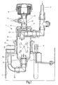
Fig. 2 ein gegenüberFig. 1 vergrößert gezeichneter Vertikalschnitt, der lediglich denjenigen Teilbereich vonFig. 1 zeigt, in dem das Ausführungsbeispiel der erfindungsgemäßen Einrichtung an den Tank des Kühlaggregates angebaut ist. - Nachstehend ist die Erfindung anhand eines Beispieles beschrieben, bei dem die erfindungsgemäße Einrichtung Bestandteil eines Kühlaggregates bildet, das in
Fig. 1 als Ganzes mit 1 bezeichnet ist und das im praktischen Einsatz zur Kühlung einer Werkzeugmaschine vorgesehen ist. Genauer gesagt, handelt es sich um die Rotorkühlung sowie die Statorkühlung der-Werkzeugmaschine, wobei vom Rotor her warme, mit Lufteinschlüssen belastete Rücklauf-Kühlflüssigkeit über einen Anschluß 3 in das Aggregat 1 eintritt. Dieses Mediengemisch (Kühlflüssigkeit mit Lufteinschlüssen) durchläuft eine Trenneinrichtung 5, bevor sie in einen Ausgleichs- oder Vorratstank 7 gelangt. Von der warmen Seite des Stators rücklaufende Kühlflüssigkeit, die nicht mit Lufteinschlüssen belastet ist, tritt über einen Anschluß 9 in das Aggregat 1 ein und gelangt unmittelbar ins Innere des Tanks 7. In diesem befindet sich eine Vorrats- oder Ausgleichsmenge entgaster Kühlflüssigkeit, wobei die inFig. 2 mit 11 bezeichnete Füllstandshöhe, eingebracht über einen Tankverschluß 13 mit Belüftung, durch einen Füllstandsanzeiger 15 überwacht ist. - Eine Tauchpumpe 17 fördert aus dem Tank 7 Kühlflüssigkeit über eine einen Manometer 18 enthaltende Leitung 19 zu einem Wärmetauscher 21, in dem mittels externer Kühlmittelzufuhr (nicht dargestellt) die zur Kühlung der Werkzeugmaschine erforderlich Wärmeabfuhr stattfindet. Aus dem Wärmetauscher 21 gelangt über Anschlüsse 23 und 25 die gekühlte Vorlaufflüssigkeit zum Rotor bzw. Stator.
- Die
Fig. 2 zeigt nähere Einzelheiten der Einrichtung zur Abscheidung von Luft aus dem über den Anschluß 3 zugeführten Mediengemisch. Wesentlicher Bestandteil der hierfür vorgesehenen Trenneinrichtung 5 ist eine Trennkammer 27, die sich entlang einer vertikalen Hochachse erstreckt, am Kammerboden einen Ausgang 29 besitzt und am entgegengesetzten, oberen Ende durch einen Kammerdeckel 31 abgeschlossen ist. Für das Einströmen des Mediengemisches vom Anschluß 3 her befindet sich in der Nähe des Kammerdeckels 31 ein Einlass 33. - Wie aus
Fig. 2 ersichtlich ist, ist die Kammer 27 auf der Tankdeckwand 35 derart aufgebaut, dass sich der bodennahe Teilbereich der Kammer 27 durch eine Öffnung der Tankdeckwand 35 ins Innere des Tanks 7 erstreckt. An dem einen offenen Durchgang bildenden bodenseitigen Ausgang 29 der Kammer 27 schließt sich ein Siphon 37 allgemein üblicher Konfiguration an, der sich bei der inFig. 2 verdeutlichten Bauweise zur Gänze innerhalb des Tanks 7 befindet. Dabei ist die Dimensionierung des Siphons 37 so gewählt, dass sich seine Austrittsmündung 39 auf einem Höhenniveau befindet, das gegenüber dem Höhenniveau des Randes des Ausganges 29 um eine Strecke nach oben versetzt ist. Diese Versetzung ist so gewählt, dass im Inneren der Kammer 27 oberhalb des bodenseitigen Ausganges 29 ein Pegel bestimmter, gewünschter Pegelhöhe des von Lufteinschlüssen freien, am Boden der Kammer 27 angesammelten Kühlwassers aufrecht erhalten bleibt. Der Zwischenraum zwischen dem durch den Siphon 37 festgelegten Flüssigkeitspegel und dem oberen Kammerdeckel 31 bildet einen Beruhigungsbereich für das zugeführte Mediengemisch, in dem es, wie inFig. 2 mit Bogenpfeilen 41 versinnbildlicht, zur Absonderung der Lufteinschlüsse kommt. Für das Abströmen der abgesonderten Luft, wie mit Strömungspfeilen 43 angedeutet, befindet sich im oberen Kammerdeckel 31 eine Entlüftungsöffnung 45. Der Siphon 37 weist im wesentlichen eine U-Form auf, vorzugsweise aus bogenförmigen sowie geradlinigen Leitungsabschnitten zusammengesetzt, wobei zumindest im unteren Bereich der U-Form sich eine gewisse Fluidmenge im Sinne einer Barriere ansammelt. - Da die über die Öffnung 45 austretende Luft noch mit Flüssigkeitspartikeln belastet sein kann, ist, insbesondere aus Gründen des Umweltschutzes, Vorsorge getroffen, dass die Luft nicht unmittelbar zur Umgebung gelangen kann. Diesbezüglich befindet sich am Kammerdeckel 31 ein Vor- oder Grobfilter in Form eines Drahtgestrickes 47, das nicht nur eine grobe Trennung sondern auch einen Spritzschutz bewirkt. Stromaufwärts schließt sich ein Verbindungsrohr 49 an, über das die Luft zu einer feinen Filtereinrichtung 51 gelangt, die als feines Drahtgestrick gestaltet ist und von wo die fein gefilterte Luft an die Umgebung abströmen kann.
- Am Verbindungsrohr 49 befindet sich ein Anschluß 53 als Dainageleitung, über den Sperrluft zugeführt werden kann, wenn in einer zugehörigen Maschinenanlage, beispielsweise Werkzeugmaschine, eine oder mehrere Dichtungsanordnungen vorhanden sind, die mit Sperrluft versorgt sind. Da aus solchen Dichtungsanordnungen austretende Sperrluft in geringen Mengenverhältnissen mit Betriebsmedien oder Partikeln belastet sein kann, ermöglicht es die bei der erfindungsgemäßen Einrichtung vorhandene Filteranordnung, dass die Sperrluft nicht unmittelbar zur Umgebung gelangt, sondern über das Verbindungsrohr 49 zum Feinfilter 51 gelangt, bevor der Austritt zur Umgebung erfolgt.
- Während die Erfindung vorstehend am Beispiel des Einsatzes bei einem Kühlaggregat für Maschinenanlagen, wie Werkhzeugmaschinen, beschrieben ist, versteht sich, dass die Vorteile der Erfindung für die Absonderung gasartiger Bestandteile beliebiger, andersartiger Betriebsmedien nutzbar sind, bei denen eine Trennung betreffender Medien für die Absonderung gasartiger Einschlüsse durchzuführen ist.
Claims (11)
- Einrichtung zum Absondern gasartiger Bestandteile, insbesondere von Luft, aus flüssigen Betriebsmedien in Fluidsystemen, mit einem Leitungssystem (1), das einen Vorratstank (7) und eine Fördereinrichtung (17) zum Abführen entgasten Betriebsmediums aus dem Tank (7) und zum Rückführen von gasartige Bestandteile enthaltendem Mediengemisch zum Tank (7) aufweist, wobei eine von dem zum Tank (7) zugeführten Mediengemisch durchströmbare Trenneinrichtung (5) eine Entgasung bewirkt, dadurch gekennzeichnet, dass die Trenneinrichtung (5) eine Kammer (27) für das Mediengemisch aufweist, die stromaufwärts des Tanks (7) angeordnet ist, dass die Kammer (27) an ihrem Boden, an dem sich das entgaste Medium ansammelt, einen Ausgang (29) aufweist, der mit dem Tank (7) über einen Siphon (37) verbunden ist, der in der Kammer (27) einen oberhalb des bodenseitigen Ausgangs (29) gelegenen Pegel des entgasten Mediums aufrecht erhält, dass die Austrittsmündung (39) des Siphons (37) in einen fluidfreien Raum innerhalb des Tanks (7) ausmündet, und dass die maximale Füllstandshöhe (11) im Tank (7) unterhalb der Austrittsmündung (39) liegt.
- Einrichtung nach Anspruch 1, dadurch gekennzeichnet, dass die Kammer (27) an ihrem dem Ausgang (29) entgegensetzten oberen Bereich einen Einlass (33) für das Mediengemisch aufweist und dass die vertikale Erstreckung der Kammer (27) so gewählt ist, dass zwischen dem Pegel des entgasten Mediums und dem Einlass (33) für das eingeströmte Mediengemisch ein Beruhigungsbereich für die Abtrennung von Luft gebildet ist.
- Einrichtung nach Anspruch 1 oder 2, dadurch gekennzeichnet, dass am oberen Ende der Kammer (27) eine Entlüftungsöffnung (45) für das Abströmen abgetrennter Luft aus der Kammer (27) vorhanden ist.
- Einrichtung nach Anspruch 3, dadurch gekennzeichnet, dass die Entlüftungsöffnung (45) in einem am oberen Ende der Kammer (27) angeordneten Kammerdeckel (31) vorgesehen ist, an dem eine Filtereinrichtung (47) angeordnet ist, die von der Luft durchströmbar ist, die über die Entlüftungsöffnung austritt.
- Einrichtung nach Anspruch 4, dadurch gekennzeichnet, dass am Kammerdeckel (31) eine als Grobfiltereinrichtung und als Spritzschutz dienende erste Filtereinrichtung (47) vorhanden ist.
- Einrichtung nach Anspruch 5, dadurch gekennzeichnet, dass oberhalb der ersten Filtereinrichtung (47) eine eine feine Trennung von Flüssigkeit und austretender Luft bewirkende zweite Filtereinrichtung (51) vorhanden ist, deren Reinseite einen Luftaustritt zur Umgebung bildet.
- Einrichtung nach einem der Ansprüche 1 bis 6, dadurch gekennzeichnet, dass sie mit ihrem Leitungssystem (1) Bestandteil des Kühlsystems einer Maschinenanlage ist.
- Einrichtung nach den Ansprüchen 6 und 7, dadurch gekennzeichnet, dass die Maschinenanlage mindestens eine mit Sperrluft versorgte Drainageanordnung enthält und dass im Strömungsweg stromabwärts der zweiten Filtereinrichtung (51) ein Anschluss (53) vorgesehen ist, über den Sperrluft, die aus der Lageranordnung austritt, der zweiten Filtereinrichtung (51) zuführbar ist.
- Einrichtung nach einem der Ansprüche 1 bis 8, dadurch gekennzeichnet, dass die Kammer (27) am Tank (7) derart angebaut ist, dass sie sich mit ihrem bodenseitigen Ausgang (29) durch die Tankdecke (35) ins Innere des Tanks (7) erstreckt.
- Einrichtung nach den Ansprüchen 7 und 9, dadurch gekennzeichnet, dass auch weitere Komponenten des Kühlsystems, wie Pumpe (17) der Fördereinrichtung, Wärmetauscher (21), Anzeige- und Überwachungseinrichtungen (15), Anschlusseinrichtungen (3,9,23,25) und/oder dergleichen, auf dem Tank (7) angebaut und mit diesem zu einer Baueinheit vereinigt sind.
- Einrichtung nach einem der Ansprüche 1 bis 10, dadurch gekennzeichnet, dass Austrittsmündung (39) sich auf einem Höhenniveau befindet, das gegenüber dem Höhenniveau des Randes des bodenseitigen Ausganges (29) um eine vorgebbare Strecke nach oben versetzt ist.
Applications Claiming Priority (1)
| Application Number | Priority Date | Filing Date | Title |
|---|---|---|---|
| DE200810030714 DE102008030714A1 (de) | 2008-06-27 | 2008-06-27 | Einrichtung zum Absondern gasartiger Bestandteile, insbesondere von Luft, aus flüssigen Betriebsmedien |
Publications (3)
| Publication Number | Publication Date |
|---|---|
| EP2138268A2 true EP2138268A2 (de) | 2009-12-30 |
| EP2138268A3 EP2138268A3 (de) | 2012-02-15 |
| EP2138268B1 EP2138268B1 (de) | 2016-11-02 |
Family
ID=41172162
Family Applications (1)
| Application Number | Title | Priority Date | Filing Date |
|---|---|---|---|
| EP09008191.0A Not-in-force EP2138268B1 (de) | 2008-06-27 | 2009-06-23 | Einrichtung zum Absondern gasartiger Bestandteile, insbesondere von Luft, aus flüssigen Betriebsmedien |
Country Status (2)
| Country | Link |
|---|---|
| EP (1) | EP2138268B1 (de) |
| DE (1) | DE102008030714A1 (de) |
Cited By (1)
| Publication number | Priority date | Publication date | Assignee | Title |
|---|---|---|---|---|
| US12274958B2 (en) | 2019-10-23 | 2025-04-15 | Donaldson Company, Inc. | Filtration and deaeration system |
Family Cites Families (5)
| Publication number | Priority date | Publication date | Assignee | Title |
|---|---|---|---|---|
| GB191507336A (en) * | 1915-05-15 | 1916-05-15 | Karl Baumann | Improvements in or relating to Feed Water Heaters of the Jet or Contact Type. |
| US2755888A (en) * | 1953-12-22 | 1956-07-24 | Research Corp | Closed circuit lubrication system |
| GB1339825A (en) * | 1971-07-07 | 1973-12-05 | Rolls Royce | Liquid supply systems |
| GB2260581B (en) * | 1991-10-19 | 1995-07-05 | Litton Uk Ltd | De-aeration of water-based hydraulic fluids |
| DE10140392A1 (de) * | 2001-08-23 | 2003-03-06 | Rainer Dorstewitz | Chemischer Reaktor, insbesondere zur Aufbereitung von Natriumsulfid aufweisendem Haarschlamm |
-
2008
- 2008-06-27 DE DE200810030714 patent/DE102008030714A1/de not_active Withdrawn
-
2009
- 2009-06-23 EP EP09008191.0A patent/EP2138268B1/de not_active Not-in-force
Cited By (1)
| Publication number | Priority date | Publication date | Assignee | Title |
|---|---|---|---|---|
| US12274958B2 (en) | 2019-10-23 | 2025-04-15 | Donaldson Company, Inc. | Filtration and deaeration system |
Also Published As
| Publication number | Publication date |
|---|---|
| DE102008030714A1 (de) | 2009-12-31 |
| EP2138268B1 (de) | 2016-11-02 |
| EP2138268A3 (de) | 2012-02-15 |
Similar Documents
| Publication | Publication Date | Title |
|---|---|---|
| DE102008008132B4 (de) | Luftabscheider für Kühlsysteme mit niedriger Strömungsrate | |
| DE19945323B4 (de) | Brennstoffzellensystem | |
| DE112007000896B4 (de) | Koaleszenzfilterbaugruppe | |
| DE102007054901B4 (de) | Ölbehälter mit Ölfilter | |
| DE102014000903B4 (de) | Filterelement und Filtervorrichtung | |
| DE102014226508B4 (de) | Klimaanlage | |
| DE2827022A1 (de) | Wasserbehaelter als reservedruckbehaelter | |
| EP3298241A1 (de) | Ölgeschmierte drehschieber-vakuumpumpe mit ölabscheide- und wiederaufbereitungseinrichtung | |
| DE202006020790U1 (de) | Filtersystem für Flüssigkeit mit Heizung | |
| DE102013204827B4 (de) | Feinfilter für strömende Flüssigkeiten | |
| DE102016009487B4 (de) | Abscheideelement, Vorrichtung sowie Verfahren zur Abscheidung von Flüssigkeit aus Rohgas oder aus Rohgasgemisch einer Kraftmaschine oder eines Kompressors | |
| DE3002578A1 (de) | Einrichtung zum entlueften und entgasen eines fluessigkeitskreislaufes | |
| EP2138268B1 (de) | Einrichtung zum Absondern gasartiger Bestandteile, insbesondere von Luft, aus flüssigen Betriebsmedien | |
| EP0504596A2 (de) | Druckluftversorgungseinrichtung für Druckluftanlagen von Fahrzeugen | |
| EP0004326A2 (de) | Einrichtung zur Entwicklung von Druckplatten mit einem Behandlungsflüssigkeit aufnehmenden Tank | |
| DE202004011911U1 (de) | Vorrichtung zum Kühlen und Filtern eines kreislaufgeführten Fluids sowie zugehöriges Gehäuse | |
| DE102010061581A1 (de) | Schmiermittelableitsystem für einen wasserstoffgekühlten Generator | |
| EP3516234A1 (de) | Schraubenkompressor für ein nutzfahrzeug | |
| EP3683077A1 (de) | Kühlvorrichtung | |
| DE19736029A1 (de) | Einrichtung zum Entgasen eines Filters | |
| DE102013018166B4 (de) | Filtersystem mit Wasserauslassöffnung | |
| DE4323832C2 (de) | Verfahren zur Reinigung von Fahrzeugbremsen | |
| DE10316652A1 (de) | Luftfilter für eine Brennkraftmaschine | |
| DE2948868C2 (de) | Filteranordnung für Flüssigkeiten | |
| DE2852416A1 (de) | Fluessigkeitssystem mit zusatztank und mehreren ausgleichsleitungen |
Legal Events
| Date | Code | Title | Description |
|---|---|---|---|
| PUAI | Public reference made under article 153(3) epc to a published international application that has entered the european phase |
Free format text: ORIGINAL CODE: 0009012 |
|
| AK | Designated contracting states |
Kind code of ref document: A2 Designated state(s): AT BE BG CH CY CZ DE DK EE ES FI FR GB GR HR HU IE IS IT LI LT LU LV MC MK MT NL NO PL PT RO SE SI SK TR |
|
| PUAL | Search report despatched |
Free format text: ORIGINAL CODE: 0009013 |
|
| AK | Designated contracting states |
Kind code of ref document: A3 Designated state(s): AT BE BG CH CY CZ DE DK EE ES FI FR GB GR HR HU IE IS IT LI LT LU LV MC MK MT NL NO PL PT RO SE SI SK TR |
|
| AX | Request for extension of the european patent |
Extension state: AL BA RS |
|
| RIC1 | Information provided on ipc code assigned before grant |
Ipc: B23Q 11/10 20060101AFI20120111BHEP Ipc: B01D 19/00 20060101ALI20120111BHEP Ipc: F16N 39/00 20060101ALI20120111BHEP Ipc: F01P 3/22 20060101ALI20120111BHEP Ipc: F01P 11/02 20060101ALI20120111BHEP Ipc: F01M 11/08 20060101ALI20120111BHEP Ipc: F01M 13/04 20060101ALI20120111BHEP Ipc: C02F 1/20 20060101ALI20120111BHEP |
|
| 17P | Request for examination filed |
Effective date: 20121004 |
|
| GRAP | Despatch of communication of intention to grant a patent |
Free format text: ORIGINAL CODE: EPIDOSNIGR1 |
|
| INTG | Intention to grant announced |
Effective date: 20160609 |
|
| GRAS | Grant fee paid |
Free format text: ORIGINAL CODE: EPIDOSNIGR3 |
|
| GRAA | (expected) grant |
Free format text: ORIGINAL CODE: 0009210 |
|
| AK | Designated contracting states |
Kind code of ref document: B1 Designated state(s): AT BE BG CH CY CZ DE DK EE ES FI FR GB GR HR HU IE IS IT LI LT LU LV MC MK MT NL NO PL PT RO SE SI SK TR |
|
| REG | Reference to a national code |
Ref country code: GB Ref legal event code: FG4D Free format text: NOT ENGLISH |
|
| REG | Reference to a national code |
Ref country code: AT Ref legal event code: REF Ref document number: 841340 Country of ref document: AT Kind code of ref document: T Effective date: 20161115 Ref country code: CH Ref legal event code: EP |
|
| REG | Reference to a national code |
Ref country code: IE Ref legal event code: FG4D Free format text: LANGUAGE OF EP DOCUMENT: GERMAN |
|
| REG | Reference to a national code |
Ref country code: DE Ref legal event code: R096 Ref document number: 502009013286 Country of ref document: DE |
|
| REG | Reference to a national code |
Ref country code: RO Ref legal event code: EPE |
|
| PG25 | Lapsed in a contracting state [announced via postgrant information from national office to epo] |
Ref country code: LV Free format text: LAPSE BECAUSE OF FAILURE TO SUBMIT A TRANSLATION OF THE DESCRIPTION OR TO PAY THE FEE WITHIN THE PRESCRIBED TIME-LIMIT Effective date: 20161102 |
|
| REG | Reference to a national code |
Ref country code: NL Ref legal event code: MP Effective date: 20161102 |
|
| REG | Reference to a national code |
Ref country code: LT Ref legal event code: MG4D |
|
| PG25 | Lapsed in a contracting state [announced via postgrant information from national office to epo] |
Ref country code: NO Free format text: LAPSE BECAUSE OF FAILURE TO SUBMIT A TRANSLATION OF THE DESCRIPTION OR TO PAY THE FEE WITHIN THE PRESCRIBED TIME-LIMIT Effective date: 20170202 Ref country code: SE Free format text: LAPSE BECAUSE OF FAILURE TO SUBMIT A TRANSLATION OF THE DESCRIPTION OR TO PAY THE FEE WITHIN THE PRESCRIBED TIME-LIMIT Effective date: 20161102 Ref country code: GR Free format text: LAPSE BECAUSE OF FAILURE TO SUBMIT A TRANSLATION OF THE DESCRIPTION OR TO PAY THE FEE WITHIN THE PRESCRIBED TIME-LIMIT Effective date: 20170203 Ref country code: NL Free format text: LAPSE BECAUSE OF FAILURE TO SUBMIT A TRANSLATION OF THE DESCRIPTION OR TO PAY THE FEE WITHIN THE PRESCRIBED TIME-LIMIT Effective date: 20161102 Ref country code: LT Free format text: LAPSE BECAUSE OF FAILURE TO SUBMIT A TRANSLATION OF THE DESCRIPTION OR TO PAY THE FEE WITHIN THE PRESCRIBED TIME-LIMIT Effective date: 20161102 |
|
| PG25 | Lapsed in a contracting state [announced via postgrant information from national office to epo] |
Ref country code: IS Free format text: LAPSE BECAUSE OF FAILURE TO SUBMIT A TRANSLATION OF THE DESCRIPTION OR TO PAY THE FEE WITHIN THE PRESCRIBED TIME-LIMIT Effective date: 20170302 Ref country code: PT Free format text: LAPSE BECAUSE OF FAILURE TO SUBMIT A TRANSLATION OF THE DESCRIPTION OR TO PAY THE FEE WITHIN THE PRESCRIBED TIME-LIMIT Effective date: 20170302 Ref country code: ES Free format text: LAPSE BECAUSE OF FAILURE TO SUBMIT A TRANSLATION OF THE DESCRIPTION OR TO PAY THE FEE WITHIN THE PRESCRIBED TIME-LIMIT Effective date: 20161102 Ref country code: FI Free format text: LAPSE BECAUSE OF FAILURE TO SUBMIT A TRANSLATION OF THE DESCRIPTION OR TO PAY THE FEE WITHIN THE PRESCRIBED TIME-LIMIT Effective date: 20161102 Ref country code: PL Free format text: LAPSE BECAUSE OF FAILURE TO SUBMIT A TRANSLATION OF THE DESCRIPTION OR TO PAY THE FEE WITHIN THE PRESCRIBED TIME-LIMIT Effective date: 20161102 Ref country code: HR Free format text: LAPSE BECAUSE OF FAILURE TO SUBMIT A TRANSLATION OF THE DESCRIPTION OR TO PAY THE FEE WITHIN THE PRESCRIBED TIME-LIMIT Effective date: 20161102 |
|
| PG25 | Lapsed in a contracting state [announced via postgrant information from national office to epo] |
Ref country code: DK Free format text: LAPSE BECAUSE OF FAILURE TO SUBMIT A TRANSLATION OF THE DESCRIPTION OR TO PAY THE FEE WITHIN THE PRESCRIBED TIME-LIMIT Effective date: 20161102 Ref country code: SK Free format text: LAPSE BECAUSE OF FAILURE TO SUBMIT A TRANSLATION OF THE DESCRIPTION OR TO PAY THE FEE WITHIN THE PRESCRIBED TIME-LIMIT Effective date: 20161102 Ref country code: CZ Free format text: LAPSE BECAUSE OF FAILURE TO SUBMIT A TRANSLATION OF THE DESCRIPTION OR TO PAY THE FEE WITHIN THE PRESCRIBED TIME-LIMIT Effective date: 20161102 Ref country code: EE Free format text: LAPSE BECAUSE OF FAILURE TO SUBMIT A TRANSLATION OF THE DESCRIPTION OR TO PAY THE FEE WITHIN THE PRESCRIBED TIME-LIMIT Effective date: 20161102 |
|
| REG | Reference to a national code |
Ref country code: DE Ref legal event code: R097 Ref document number: 502009013286 Country of ref document: DE |
|
| PG25 | Lapsed in a contracting state [announced via postgrant information from national office to epo] |
Ref country code: IT Free format text: LAPSE BECAUSE OF FAILURE TO SUBMIT A TRANSLATION OF THE DESCRIPTION OR TO PAY THE FEE WITHIN THE PRESCRIBED TIME-LIMIT Effective date: 20161102 Ref country code: BG Free format text: LAPSE BECAUSE OF FAILURE TO SUBMIT A TRANSLATION OF THE DESCRIPTION OR TO PAY THE FEE WITHIN THE PRESCRIBED TIME-LIMIT Effective date: 20170202 |
|
| PLBE | No opposition filed within time limit |
Free format text: ORIGINAL CODE: 0009261 |
|
| STAA | Information on the status of an ep patent application or granted ep patent |
Free format text: STATUS: NO OPPOSITION FILED WITHIN TIME LIMIT |
|
| 26N | No opposition filed |
Effective date: 20170803 |
|
| PG25 | Lapsed in a contracting state [announced via postgrant information from national office to epo] |
Ref country code: SI Free format text: LAPSE BECAUSE OF FAILURE TO SUBMIT A TRANSLATION OF THE DESCRIPTION OR TO PAY THE FEE WITHIN THE PRESCRIBED TIME-LIMIT Effective date: 20161102 |
|
| PG25 | Lapsed in a contracting state [announced via postgrant information from national office to epo] |
Ref country code: MC Free format text: LAPSE BECAUSE OF FAILURE TO SUBMIT A TRANSLATION OF THE DESCRIPTION OR TO PAY THE FEE WITHIN THE PRESCRIBED TIME-LIMIT Effective date: 20161102 |
|
| REG | Reference to a national code |
Ref country code: CH Ref legal event code: PL |
|
| GBPC | Gb: european patent ceased through non-payment of renewal fee |
Effective date: 20170623 |
|
| REG | Reference to a national code |
Ref country code: IE Ref legal event code: MM4A |
|
| REG | Reference to a national code |
Ref country code: FR Ref legal event code: ST Effective date: 20180228 |
|
| PG25 | Lapsed in a contracting state [announced via postgrant information from national office to epo] |
Ref country code: LU Free format text: LAPSE BECAUSE OF NON-PAYMENT OF DUE FEES Effective date: 20170623 Ref country code: LI Free format text: LAPSE BECAUSE OF NON-PAYMENT OF DUE FEES Effective date: 20170630 Ref country code: IE Free format text: LAPSE BECAUSE OF NON-PAYMENT OF DUE FEES Effective date: 20170623 Ref country code: CH Free format text: LAPSE BECAUSE OF NON-PAYMENT OF DUE FEES Effective date: 20170630 Ref country code: GB Free format text: LAPSE BECAUSE OF NON-PAYMENT OF DUE FEES Effective date: 20170623 |
|
| REG | Reference to a national code |
Ref country code: BE Ref legal event code: MM Effective date: 20170630 |
|
| PG25 | Lapsed in a contracting state [announced via postgrant information from national office to epo] |
Ref country code: FR Free format text: LAPSE BECAUSE OF NON-PAYMENT OF DUE FEES Effective date: 20170630 |
|
| PGFP | Annual fee paid to national office [announced via postgrant information from national office to epo] |
Ref country code: DE Payment date: 20180630 Year of fee payment: 10 |
|
| PG25 | Lapsed in a contracting state [announced via postgrant information from national office to epo] |
Ref country code: BE Free format text: LAPSE BECAUSE OF NON-PAYMENT OF DUE FEES Effective date: 20170630 |
|
| PGFP | Annual fee paid to national office [announced via postgrant information from national office to epo] |
Ref country code: AT Payment date: 20180626 Year of fee payment: 10 Ref country code: RO Payment date: 20180618 Year of fee payment: 10 |
|
| PG25 | Lapsed in a contracting state [announced via postgrant information from national office to epo] |
Ref country code: MT Free format text: LAPSE BECAUSE OF FAILURE TO SUBMIT A TRANSLATION OF THE DESCRIPTION OR TO PAY THE FEE WITHIN THE PRESCRIBED TIME-LIMIT Effective date: 20161102 |
|
| PG25 | Lapsed in a contracting state [announced via postgrant information from national office to epo] |
Ref country code: HU Free format text: LAPSE BECAUSE OF FAILURE TO SUBMIT A TRANSLATION OF THE DESCRIPTION OR TO PAY THE FEE WITHIN THE PRESCRIBED TIME-LIMIT; INVALID AB INITIO Effective date: 20090623 |
|
| PG25 | Lapsed in a contracting state [announced via postgrant information from national office to epo] |
Ref country code: CY Free format text: LAPSE BECAUSE OF NON-PAYMENT OF DUE FEES Effective date: 20161102 |
|
| PG25 | Lapsed in a contracting state [announced via postgrant information from national office to epo] |
Ref country code: MK Free format text: LAPSE BECAUSE OF FAILURE TO SUBMIT A TRANSLATION OF THE DESCRIPTION OR TO PAY THE FEE WITHIN THE PRESCRIBED TIME-LIMIT Effective date: 20161102 |
|
| REG | Reference to a national code |
Ref country code: DE Ref legal event code: R119 Ref document number: 502009013286 Country of ref document: DE |
|
| PG25 | Lapsed in a contracting state [announced via postgrant information from national office to epo] |
Ref country code: RO Free format text: LAPSE BECAUSE OF NON-PAYMENT OF DUE FEES Effective date: 20190623 |
|
| REG | Reference to a national code |
Ref country code: AT Ref legal event code: MM01 Ref document number: 841340 Country of ref document: AT Kind code of ref document: T Effective date: 20190623 |
|
| PG25 | Lapsed in a contracting state [announced via postgrant information from national office to epo] |
Ref country code: TR Free format text: LAPSE BECAUSE OF FAILURE TO SUBMIT A TRANSLATION OF THE DESCRIPTION OR TO PAY THE FEE WITHIN THE PRESCRIBED TIME-LIMIT Effective date: 20161102 |
|
| PG25 | Lapsed in a contracting state [announced via postgrant information from national office to epo] |
Ref country code: DE Free format text: LAPSE BECAUSE OF NON-PAYMENT OF DUE FEES Effective date: 20200101 Ref country code: AT Free format text: LAPSE BECAUSE OF NON-PAYMENT OF DUE FEES Effective date: 20190623 |