EP2137015B1 - Kugelkupplung mit relativbeweglich aufgenommener dichtung - Google Patents
Kugelkupplung mit relativbeweglich aufgenommener dichtung Download PDFInfo
- Publication number
- EP2137015B1 EP2137015B1 EP08716636A EP08716636A EP2137015B1 EP 2137015 B1 EP2137015 B1 EP 2137015B1 EP 08716636 A EP08716636 A EP 08716636A EP 08716636 A EP08716636 A EP 08716636A EP 2137015 B1 EP2137015 B1 EP 2137015B1
- Authority
- EP
- European Patent Office
- Prior art keywords
- coupling
- seal
- ball
- socket
- sealing
- Prior art date
- Legal status (The legal status is an assumption and is not a legal conclusion. Google has not performed a legal analysis and makes no representation as to the accuracy of the status listed.)
- Active
Links
Images


Classifications
-
- B—PERFORMING OPERATIONS; TRANSPORTING
- B60—VEHICLES IN GENERAL
- B60D—VEHICLE CONNECTIONS
- B60D1/00—Traction couplings; Hitches; Draw-gear; Towing devices
- B60D1/01—Traction couplings or hitches characterised by their type
- B60D1/06—Ball-and-socket hitches, e.g. constructional details, auxiliary devices, their arrangement on the vehicle
- B60D1/065—Ball-and-socket hitches, e.g. constructional details, auxiliary devices, their arrangement on the vehicle characterised by the hitch mechanism
Definitions
- the present invention relates to a ball coupling for coupling a traction vehicle with a trailing vehicle, comprising a with one of the vehicles: tractor or trailer vehicle, connected or connectable coupling ball and connected to the other vehicle or connectable coupling socket, which is coupled to the coupling ball, more precisely the coupling ball has a convex abutment region and the coupling socket in a coupling recess has a concave counter contact area, which areas abut each other in the coupling state of the ball coupling to form a Kupplungsstrom Gebs and between which the coupling ball and the coupling socket are disconnected during disengagement of the ball coupling, further comprising a coupling element: coupling socket or coupling ball, carries a seal which seals the clutch engagement area against the environment in the coupling state.
- Such a ball coupling is from the DE 10 2005 022 879 A1 known.
- the seal is held rigidly by the coupling element carrying it and bears sealingly against the coupling element which does not carry it. It has been found to be disadvantageous that change by material abrasion in the coupling system area with increasing operation of the ball coupling, the relative positions of coupling ball and coupling socket in the coupling state and thereby changes the investment situation of the seal on the other, they do not support coupling element. As a result, locally very high loads can act on the seal, which can lead to impairment of the sealing effect at this point.
- a ball coupling of the type mentioned in which the seal, based on a in the coupling state, the center of the coupling ball containing and the coupling recess of the coupling socket substantially centrally passing through the coupling axis, with radial movement play in which it carries the coupling element.
- the seal can at operational displacement of the coupling elements relative to each other and concomitant change their investment state in the non-supporting coupling element, such as material abrasion on the coupling ball and / or the coupling socket, due to the radial movement relative to the game move supporting coupling element, which avoids an undesirably high operating load on the seal and an undesirable lifting of the coupling element of the seal.
- the seal which is applied to ensure their sealing effect under self-bias on the non-supporting coupling element, thus can be applied over a very long period of operation with a substantially constant bias and thus constant sealing effect in the coupling state on the non-supporting coupling element.
- Seal in the sense of the present application refers to a sealing body, which is stably held on the coupling element receiving the seal and on which a sealing region is provided, which is designed to rest on the respective other coupling element.
- the sealing area may be only a surface portion of the seal body, such as an O-ring seal, or may be a sealing geometry provided on the seal body, preferably protruding therefrom, such as a sealing lip arrangement. If it is stated in this application that the seal bears against a coupling element, so that the system of the sealing region is designated at this.
- the above-mentioned coupling axis serves as a coordinate system for defining an axial and a radial direction and a circumferential direction.
- the coupling recess is designated, in which the coupling ball during manufacture of the coupling state, that is, when coupling, is introduced, abut contact surface and counter-bearing surface to each other. Therefore, the coupling recess is usually at least partially spherical.
- the clutch axle should therefore be viewed in an idealized condition, such as with un-worn coupling elements when driving straight ahead on a flat horizontal roadway.
- the coupling axis includes the center of the coupling ball, further includes the center of the spherical portion of the coupling recess of the coupling socket, and is substantially orthogonal to the road surface.
- the peripheral seal may be formed in a particularly simple, but due to its high sealing effect, but also preferred case by an O-ring.
- the sealing ring can be obtained by a primary molding process, such as injection molding or injection molding.
- the circumferential seal can be accommodated in the coupling element carrying it in an annular receiving recess.
- a sufficient sealing effect against the the seal-carrying coupling element can be provided by axial deformation of the seal in the annular receiving recess.
- the seal is received with axial play in the receiving recess to ensure their mobility in the radial direction, since the seal is sufficient only as a dirt seal and then it does not depend on the sealing effect against the seal-carrying coupling element as much as on the sealing effect the other coupling element.
- the receiving recess may be formed in the coupling ball, then for providing the radial play of movement, the diameter of the receiving recess in the radial direction limiting radial boundary wall portion is smaller than the inside diameter of the passage opening of the inserted into the receiving recess circumferential seal.
- the inserted seal in the coupling state ie in its state of axial deformation when it rests against the non-supporting coupling element, since usually an axial compression of the seal inevitably leads to a radial deformation of the seal, in such a way that the light Width of the passage opening is smaller than in the axially undeformed state.
- the receiving recess can be formed in the coupling socket, the receiving recess, in which case to ensure the radial play of movement of the seal, the diameter of the receiving recess defining in the radial direction radial boundary wall portion is greater than the outer diameter of the inserted into the receiving recess seal.
- the inserted gasket is to be considered in its axial deformation state under contact with the coupling element which does not carry it.
- the passage opening of the peripheral seal is penetrated by the coupling ball, on which the seal rests sealingly.
- the seal may be floatingly received, i. the seal is - apart from frictional forces - free of forces in the radial direction, in particular free of tension, received in the receiving recess.
- a radially between the seal and the Radialbegrenzungswandabmale the receiving recess existing gap, preferably annular gap space is thus apart from operational possibly resulting minor and not interesting dirt deposits substantially free of other components and thus substantially fluid-filled, such as lubricant-filled, especially oil and / or fat-filled, and / or gas, in particular air-filled.
- a particularly efficient sealing of the clutch contact area against the entry of dirt from the outside in these can be achieved in recorded on the coupling socket seal that the aforementioned sealing area, viewed in a arranged on the coupling socket, unloaded uncoupled state in a a cutting plane containing a central axis of the peripheral seal, protrudes from the sealing body as a sealing lip, with an extension component in the radial direction to the central axis and with an extension component in the axial direction of an opening of the coupling recess of the coupling socket path.
- the extension component in the axial direction of the mouth of the coupling socket away provides a gentle way to set up the coupling socket for producing a coupling connection with the greatest possible protection of the seal on the coupling ball.
- the sealing area is very good at the coupling ball produced at the coupling state.
- the edge region of the coupling recess which opens towards the environment is designated in this application.
- the central axis of the peripheral seal In the coupling state usually coincides the central axis of the peripheral seal with the aforementioned coupling axis.
- the central axis can also be determined independently of other components of the ball coupling: it is usually about the symmetry center axis of the circumferential seal.
- the most stable possible seal can be obtained in the high operational load that acts on them, that the sealing area in the axial direction closer to the muzzle closer end of the seal body protrudes from this.
- the muzzle closer end face of the sealing body is steplessly in the sealing area over. This can be undesirable because the integrity of the seal hazardous voltage spikes in the seal can be avoided.
- a particularly good mobility of the sealing region protruding as a sealing lip in the radial direction and in the axial direction can be ensured by the fact that the cross section of the sealing body at least partially tapers in the axial direction towards the mouth of the coupling socket or away from it. This mobility facilitates making the coupling state without damaging the seal.
- a particularly favorable for the coupling mobility of the sealing region be provided by a radially inner boundary surface of the seal body with respect to the central axis of the seal at least partially, preferably from the sealing region in the axial direction is conical.
- a particularly high strength of the seal body and thus a high stability of the seal as a whole can be ensured that a radially outer boundary surface of the seal body with respect to the central axis of the seal at least partially, preferably completely cylindrical.
- a radially outer boundary surface of the seal body with respect to the central axis of the seal is at least partially, preferably completely conical.
- the seal in particular the sealing body, at least one channel, preferably a plurality of channels, which passes through the seal in the radial direction.
- lubricant can also get into the gap receiving the seal and thus ensure a pressure equalization of the forces acting on the seal, in particular the seal body, fluid forces:
- the channels in the seal in particular in the sealing body, can be produced particularly simply by forming the at least one channel as an axial depression in one of the end faces pointing in the axial direction.
- the channels are advantageously arranged at least in part, but preferably completely, in the circumferential direction with substantially the same distance from each other.
- the channels serve as flow channels, the flow resistance of the channel can be reduced by forming the channel with the shortest possible length. This may be realized structurally, for example, by the fact that the at least one channel or the plurality of channels extends in the radial direction, without a substantial extension component in the circumferential direction or in the axial direction.
- a lubricating nipple may be provided on one of the coupling elements, preferably on the coupling socket, with which a lubricant, usually about grease, can be introduced between coupling socket and coupling ball. Then it is especially preferable Although the seal, although liquid-tight, but not gas-tight, on which it bears not sealing coupling element. As a result, the lubricant displace existing between coupling socket and coupling ball air into the environment, but is itself retained by the seal so that it remains as desired between the coupling socket and coupling ball.
- the "sealing effect" of a coupling gasket referred to in this application does not mean a “sealing effect” in the conventional sense, but essentially a dirt-repellent (sealing) effect which substantially reduces, preferably completely avoids, the undesirable entry of dirt into the coupling installation region.
- a depression can be formed on the surface of at least one of the coupling elements.
- a spring arrangement may be provided in the ball coupling, which exerts the centering spring force on the seal.
- Meandering springs or elastomer components have proven to be particularly suitable.
- This spring arrangement in particular the said meander spring, can be accommodated radially between the seal and a radial boundary wall section which delimits a receiving recess receiving the seal in the radial direction. This can be avoided that the ball coupling must be formed for receiving the spring assembly in the axial direction with larger dimensions.
- just a meander spring requires very little space and can be conveniently accommodated in radial gap with small radial expansion.
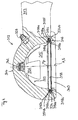
- FIG. 1 a first embodiment of a ball coupling according to the invention is generally designated 10.
- the ball coupling 10 and 10 comprises a coupling socket 12, which is formed integrally with a drawbar 13 with this. It further comprises a coupling ball 14, which is inserted into a part-spherical coupling recess 15 of the coupling socket 12.
- An abutment portion 20 of the coupling ball 14 is applied to a counter-contact area 22 of the coupling socket 12 and thus forms in the in FIG. 1 illustrated coupling state a clutch system area 24th
- the coupling axis A contains the center Mk of the coupling ball 14 and the center Mp of the coupling recess 15 and passes through the part-spherical coupling recess 15 centrally.
- annular groove 16 is formed, which is also centrally penetrated by the coupling axis A.
- the annular groove 16 is located in a direction orthogonal to the coupling axis A level.
- the annular groove 16 has two spaced-apart, substantially parallel axial boundary wall sections 16a and 16b which bound the annular groove 16 in the axial direction, and comprises a radial boundary wall section 16c located in the axial direction between the boundary wall sections 16a and 16b Ring groove 16 bounded radially outward.
- a seal 18 in the form of an O-ring such recorded that this is applied under axial compression deformation at the axial boundary wall portions 16 a and 16 b.
- the O-ring 18 may also be received with axial clearance in the annular groove.
- the O-ring 18 is sealingly against the surface of the coupling ball 14, on the side facing away from the coupling socket 12 hemisphere portion 19th
- annular gap 34 between the outer diameter of the O-ring 18 and the radial boundary wall portion 16c, which is in the in FIG. 1 shown example over the circumference of the annular groove 16 is formed uniformly.
- An annular gap section 34a can be seen on the side of the ball coupling remote from the drawbar and an annular gap section 34b, which is substantially the same size in the radial direction, on the drawbar side of the ball coupling.
- This annular gap 34 is fluid-filled, ie filled with ambient air or / and with lubricant, in particular lubricating grease.
- the floating bearing seal 18 may therefore, if necessary, move in the radial direction in the annular groove 16 relative to the female coupling socket 12 receiving it.
- the counter-contact area 22 of the coupling ball 12 has a recess 26 which serves as a grease reservoir. Via a grease nipple 28 provided in the coupling socket 12, lubricating grease can be pressed in between the contact region 20 and the counter-contact region 22, in particular into the depression 26.
- FIG. 2 a second embodiment of a ball coupling according to the invention is shown.
- the same components as in the first embodiment are denoted by the same reference numerals in the second embodiment but increased by the number 100.
- the second embodiment will be described only insofar as it differs from the first embodiment. Otherwise, reference is expressly made to the above description of the first embodiment.
- the second embodiment is different from that in FIG. 1 shown only in that the seal 118 of the second embodiment is a stamped sealing ring which is punched out of a sealing material layer.
- FIG. 3 a third embodiment of a ball coupling according to the invention is shown.
- the same components as in the first and second embodiments are shown in FIG. 3 provided with the same reference numerals, but increased by the number 200 or 100.
- the in FIG. 3 illustrated third embodiment is explained in the following only insofar as it differs from the first two embodiments, whose detailed explanation otherwise expressly referenced.
- the seal 218 of FIG. 3 is a seal produced by spray technology.
- the ball coupling 210 is shown after a long period of operation, so that due to material abrasion of the contact area 220 and the counter-investment area 222 have no more matching diameter, which means that when a relative tensile force in the direction of arrow 230 between the coupling ball 214 and the coupling socket 212th acts, the two coupling elements lie along a smaller compared to the previously shown embodiments Kupplungsstrom Anlagen Schemes 224 and a gap 232 between the contact area 220 and the counter-investment area 222 consists.
- the coupling system area 224 is in this case a Schmiegezone in which the contact area 220 and the counter-investment area 222 due to their very similar despite the wear diameter diameter abut one another.
- the centers Mk of the coupling ball 214 and Mp of the coupling socket 212 fall apart.
- the seal 218 is selected with its dimensions, in particular its opening diameter in the undeformed state, your sealing material and their sealing location on the coupling ball 214 so that grease, which is filled through the lubricating nipple 228 between the coupling ball 214 and the coupling socket 212, from the seal 218th
- the incoming grease may possibly displace existing between the coupling ball 214 and the coupling socket 212 existing air over the seal 218 away into the environment.
- this dimensioning of the seals applies to all embodiments shown in the present application.
- FIGS. 1 to 3 not shown is the possible inclusion of a meander spring or an elastomeric component in the annular gaps 34, 134 and 234, which ensures a centering of the respective seal 18, 118 and 218 with respect to the coupling axis A.
- FIG. 4 a ball socket of a fourth embodiment of a ball coupling according to the invention is shown.
- FIG. 4 The embodiment shown is explained only insofar as it differs from the preceding embodiments. Same components as in the embodiments of FIGS. 1 to 3 are given the same reference numerals but increased by the number 300 with respect to the first embodiment in FIG. 1 to the number 200 with respect to the second embodiment in FIG. 2 and increased by the number 100 with respect to the third embodiment in FIG. 3 , For a detailed description of the already known components is expressly to the description of FIGS. 1 to 3 directed.
- a central axis S of the circumferential elastomeric seal arranged in the annular groove 316 coincides with the coupling axis A. This applies if the seal 318, as in FIG. 4 shown, centered in the annular groove 316 is received, but this is due to the floating mounting of the seal 318 in the annular groove 316 random.
- the center axis S of the seal 318 is a rotational symmetry axis of the seal 318.
- the cross-sectional plane of the in FIG. 4 illustrated cross-section includes the central axis S of the seal 318 and lies in the plane of FIG. 4 ,
- the seal 318 comprises, when viewing the cross section of FIG. 4 , a sealing body 318a and a sealing lip 318a projecting from the sealing body 318a as a sealing lip.
- the end face 318c of the seal 318 facing the mouth 340 of the coupling recess 315 in the axial direction goes continuously from the sealing body 318a to the sealing area 318b over. Therefore, in the in FIG. 4 shown embodiment, the sealing region 318b from the sealing body 318a at the muzzle closer axial end thereof.
- the Abstehraum the sealing portion 318b has in each cross-section, the cross-sectional plane containing the central axis S, an extension component in the radial direction to the central axis S out and in the axial direction of the mouth 340 away, ie in the coupling recess 315 inside. This extension direction facilitates the placement of in FIG. 4 shown coupling socket 312 on a coupling ball, not shown considerably.
- the wall 318d defining the sealing body 318a is conically formed radially inward, namely with the mouth 340 of the coupling recess 315 widening opening angle. This means that the radial thickness of the sealing body 318a decreases in the axial direction from its mouth-remote end face 318e to its mouth-facing end face 318c.
- boundary wall 318f bounding the sealing body 318a and thus the seal 318 radially outward is essentially cylindrical with respect to the center axis S of the seal 318.
- the axial thickness of the seal 318 in the unloaded state ie the axial distance of the two end faces 318c and 318e is slightly smaller than the axial distance of the two Axialbegrenzungs vom 316a and 316b of the radial groove 316, so that the seal 318 in the radial groove 316 with slight axial play is already displaced by very small forces acting in the radial direction in just this direction.
- the sealing region 318b lies with its remote from the sealing body 318a Longitudinal end in the coupling state on the coupling ball on.
- valve 342 through which lubricant introduced into the clutch engagement region 322 via the grease nipple 328 can exit to lubricate a holddown engagement region 344 of the ball clutch.
- the valve 342 passes only a flow of lubricant from the coupling recess 315 to the hold-down abutment region 344 and blocks in the opposite flow direction.
- the annular gap 334 is in the in FIG. 4 Example shown either filled with air or partially or completely filled with a by the grease nipple 328 in the clutch system area 322 lubricant, in particular grease filled.
- the in the FIGS. 5a to 6b The seal 418 shown is explained only insofar as it differs from the one in FIG FIG. 4 shown seal 318, whose description is otherwise expressly referenced. Same components and component sections as in FIG. 4 are in the FIGS. 5a to 6b with the same reference numerals as in FIG FIG. 4 provided, but increased by the number 100.
- the sealing region 418b projecting from the sealing body 418a as a sealing lip encloses an angle W with the plane of the tangential plane to the mouth-near end face 418c of the seal 418.
- the angle W is advantageously in a range between about 45 ° and about 70 °.
- radial channels 446 are formed on the muzzle remote end face. These radial passages lead from the radially inner boundary surface 418d to the radially outer boundary surface 418f and thus pass through the seal body 418a in the radial direction.
- a plurality of radial channels 446 are arranged distributed in the circumferential direction at the same distance from each other over the entire seal 418. The meaning of these radial channels 446 will be described below with reference to Figures 6a and 6b explained.
- both the radially inner boundary surface 418 d of the seal body 418 a and the radially outer boundary surface 418 f of the seal body 418 a are conical, namely the radially inner boundary surface 418 d with an opening angle, which in the assembled state of the seal 418 for Mouth 440 of a coupling recess 415 is tapered and in the case of the radially outer boundary surface 418f with an opening angle which widens towards the same mouth, so that the radial thickness of the seal body 418a from the muzzle remote (mündungsfernere face 418e) axial end, which formed as axial recesses radial passages 446, towards the muzzle closer axial end (muzzle closer end face 418c) increases towards.
- the radial channels 446 are formed at the position which has the smallest thickness, so that the radial channels 446 acting as flow channels offer the lowest possible flow resistance.
- the radial channels 446 connect the annular gap 434 with the region of the coupling recess 415.
- a lubricant introduced into the region of the coupling recess 415 which threatens to radially expand the seal 418 due to the pressure exerted on the radially inner boundary surface 418d and thereby impair its sealing effect, flows via the radial channels 446 into the annular gap 334. and thus provide a pressure equalization, which the unwanted radial expansion of the seal 418 prevented.
- the seal 418 thus always lies securely against the coupling ball 414.
- D is the outside diameter of the seal
- B0 is the thickness of the muzzle nearer axial end of the seal body 418a as measured from the radially outer edge thereof to the junction of the seal body 418a with the seal portion 418b extending therefrom.
- B1 denotes the thickness of the muzzle-distal axial end of the sealing body, measured from its radially outer edge until the transition of the muzzle-remote end face 418e of the sealing body 418a to its radially inner boundary surface 418d.
- H1 denotes the axial thickness of the sealing body 418a, measured from the mouth-near end face 418c of the sealing body 418a to its mouth-distant end face 418e.
- H2 denotes the axial thickness of the solid seal body 418a, measured from its muzzle-side end face 418c to the bottom of the radial passage 446.
- H3 designates the axial height of the longitudinal end of the sealing region 418b adjacent to the seal, via a tangential plane orthogonal to the central axis of the seal, to the mouth-near end face 418c of the sealing body 418a.
- W denotes the angle at which the sealing region 418b protrudes from the plane of the mouth-near end face 418c from the sealing body 418a. If the muzzle closer end face 418c is not flat, is to determine the angle W, a tangential to the center axis of the gasket tangential plane to the muzzle closer end side.
- H4 denotes the depth of the radial channel 446, so that H1 is composed of the sum of H2 and H4.
- W2 denotes the angle which the radially outer boundary surface 418f of the sealing body 418a in the cross-sectional view of FIG FIG. 6c with a parallel to the central axis of the seal tangent to the radially outer boundary of the seal body 418a includes.
- the axial depth of the radial passage 446 is about 15% to about 25% of the total axial height H1 of the seal body 418a.
Landscapes
- Engineering & Computer Science (AREA)
- Transportation (AREA)
- Mechanical Engineering (AREA)
- Pivots And Pivotal Connections (AREA)
- Rolling Contact Bearings (AREA)
- Taps Or Cocks (AREA)
- Joints Allowing Movement (AREA)
- Pens And Brushes (AREA)
Priority Applications (1)
| Application Number | Priority Date | Filing Date | Title |
|---|---|---|---|
| PL08716636T PL2137015T3 (pl) | 2007-04-10 | 2008-03-19 | Sprzęg kulowy przyczepy z uszczelką osadzoną z ruchliwością względną |
Applications Claiming Priority (2)
| Application Number | Priority Date | Filing Date | Title |
|---|---|---|---|
| DE102007016896A DE102007016896A1 (de) | 2007-04-10 | 2007-04-10 | Kugelkupplung mit relativbeweglich aufgenommener Dichtung |
| PCT/EP2008/002218 WO2008122350A1 (de) | 2007-04-10 | 2008-03-19 | Kugelkupplung mit relativbeweglich aufgenommener dichtung |
Publications (2)
| Publication Number | Publication Date |
|---|---|
| EP2137015A1 EP2137015A1 (de) | 2009-12-30 |
| EP2137015B1 true EP2137015B1 (de) | 2011-05-18 |
Family
ID=39434246
Family Applications (1)
| Application Number | Title | Priority Date | Filing Date |
|---|---|---|---|
| EP08716636A Active EP2137015B1 (de) | 2007-04-10 | 2008-03-19 | Kugelkupplung mit relativbeweglich aufgenommener dichtung |
Country Status (9)
| Country | Link |
|---|---|
| EP (1) | EP2137015B1 (pl) |
| AT (1) | ATE509790T1 (pl) |
| AU (1) | AU2008235064B2 (pl) |
| BR (1) | BRPI0810193B1 (pl) |
| DE (1) | DE102007016896A1 (pl) |
| PL (1) | PL2137015T3 (pl) |
| RU (1) | RU2424914C1 (pl) |
| WO (1) | WO2008122350A1 (pl) |
| ZA (1) | ZA200906926B (pl) |
Cited By (1)
| Publication number | Priority date | Publication date | Assignee | Title |
|---|---|---|---|---|
| RU2726486C1 (ru) * | 2019-12-30 | 2020-07-14 | Федеральное государственное бюджетное образовательное учреждение высшего образования "Елецкий государственный университет им. И.А. Бунина" | Сцепное устройство легковесного автопоезда |
Families Citing this family (2)
| Publication number | Priority date | Publication date | Assignee | Title |
|---|---|---|---|---|
| AT513831B1 (de) * | 2013-04-09 | 2014-08-15 | Josef Ing Scharmüller | Hochlastzugöse |
| CN105757829A (zh) * | 2016-01-24 | 2016-07-13 | 余姚市苏杰电器科技有限公司 | 隔振式水冷空调室外机 |
Family Cites Families (10)
| Publication number | Priority date | Publication date | Assignee | Title |
|---|---|---|---|---|
| GB544759A (en) * | 1941-02-20 | 1942-04-27 | Carl Heimann | Ball joint |
| SU952665A1 (ru) * | 1980-10-16 | 1982-08-23 | За витель | Сцепное устройство автопоезда |
| DE3502799A1 (de) * | 1984-07-11 | 1986-07-31 | Martin Merkel GmbH & Co KG, 2102 Hamburg | Wellendichtung |
| SU1576356A1 (ru) * | 1988-10-06 | 1990-07-07 | Мытищинский Машиностроительный Завод | Замковое устройство сцепки транспортного средства |
| GB2251838B (en) * | 1991-01-16 | 1994-11-30 | Arthur Goddard | Vehicle coupling assembly |
| DE4411383A1 (de) * | 1993-05-20 | 1994-11-24 | Willimczik Wolfhart | Drehkolbenmaschinen mit einem lagerfreien Kolbentriebwerk |
| DE20116706U1 (de) * | 2001-10-11 | 2001-12-06 | Knott GmbH, 83125 Eggstätt | Zugkupplung mit Stabilisierungseinrichtung |
| US7134668B2 (en) * | 2001-10-24 | 2006-11-14 | Ebara Corporation | Differential pumping seal apparatus |
| AT412459B (de) * | 2002-06-03 | 2005-03-25 | Scharmueller Gmbh & Co Kg | Kupplungsvorrichtung |
| DE102005022879A1 (de) | 2005-05-18 | 2006-11-23 | Jost-Werke Gmbh & Co. Kg | Kugelkupplung mit abgedichtetem Anlagebereich |
-
2007
- 2007-04-10 DE DE102007016896A patent/DE102007016896A1/de not_active Withdrawn
-
2008
- 2008-03-19 AU AU2008235064A patent/AU2008235064B2/en not_active Ceased
- 2008-03-19 WO PCT/EP2008/002218 patent/WO2008122350A1/de not_active Ceased
- 2008-03-19 PL PL08716636T patent/PL2137015T3/pl unknown
- 2008-03-19 BR BRPI0810193A patent/BRPI0810193B1/pt not_active IP Right Cessation
- 2008-03-19 RU RU2009141352/11A patent/RU2424914C1/ru not_active IP Right Cessation
- 2008-03-19 AT AT08716636T patent/ATE509790T1/de active
- 2008-03-19 EP EP08716636A patent/EP2137015B1/de active Active
-
2009
- 2009-10-06 ZA ZA200906926A patent/ZA200906926B/xx unknown
Cited By (1)
| Publication number | Priority date | Publication date | Assignee | Title |
|---|---|---|---|---|
| RU2726486C1 (ru) * | 2019-12-30 | 2020-07-14 | Федеральное государственное бюджетное образовательное учреждение высшего образования "Елецкий государственный университет им. И.А. Бунина" | Сцепное устройство легковесного автопоезда |
Also Published As
| Publication number | Publication date |
|---|---|
| ATE509790T1 (de) | 2011-06-15 |
| BRPI0810193A2 (pt) | 2014-12-30 |
| PL2137015T3 (pl) | 2011-10-31 |
| DE102007016896A1 (de) | 2008-10-16 |
| WO2008122350A1 (de) | 2008-10-16 |
| AU2008235064A1 (en) | 2008-10-16 |
| BRPI0810193B1 (pt) | 2019-09-10 |
| ZA200906926B (en) | 2010-05-26 |
| RU2009141352A (ru) | 2011-05-20 |
| AU2008235064B2 (en) | 2012-02-02 |
| EP2137015A1 (de) | 2009-12-30 |
| RU2424914C1 (ru) | 2011-07-27 |
Similar Documents
| Publication | Publication Date | Title |
|---|---|---|
| EP2631499B1 (de) | Kugelgelenk | |
| DE60214212T2 (de) | Hydroelastisches kugelgelenk | |
| EP2024653B1 (de) | Wälzlager mit zwei innenringen und einer dichtungsanordnung zur abdichtung der trennfuge zwischen den innenringen | |
| EP0932774B1 (de) | Scheibenbremssattel | |
| DE60310346T2 (de) | Verschlussstopfen für eine Öffnung in einem Bauteil | |
| DE102005029614B4 (de) | Buchsenlager mit radialem und/oder axialem Anschlag und Verfahren zur Erzeugung eines Axialanschlags bei einem Buchsenlager | |
| EP1611367B1 (de) | Hydraulisch dämpfendes gummibuchsenlager für vertikale montage | |
| EP2222974A2 (de) | Wälzlagerkäfig | |
| DE102014009046A1 (de) | Kupplungsteil für eine Schnellkupplung für Hochdruckhydraulikleitungen | |
| EP2946123A1 (de) | Kugelgelenk | |
| DE3244209A1 (de) | Dichtung zum abdichten gegen hydraulische medien, vorzugsweise dichtabstreifelement | |
| EP2137015B1 (de) | Kugelkupplung mit relativbeweglich aufgenommener dichtung | |
| DE3434421A1 (de) | Selbsttaetig rueckstellbare bremsbacke fuer teilbelag-scheibenbremsen | |
| DE102014017386A1 (de) | Federfunktionsbauteil für ein hydroelastisches Lager | |
| EP1162394B1 (de) | Dichtelement für hydraulische Kolben-Zylinder-Anordnungen | |
| WO2006056171A1 (de) | Gelenk- und/oder lageranordnung | |
| DE10006178B4 (de) | Elastomerlager | |
| EP1138968A1 (de) | Labyrinthdichtung für eine Gelenkkreuzwelle | |
| DE102004018054B4 (de) | Dichtungsbalg | |
| DE102009012366B4 (de) | Dichtelement für eine Zylinder-/Kolbenanordnung einer Fahrzeugbremsanlage | |
| DE10083269B4 (de) | Kugellagerkäfig | |
| DE10335514B4 (de) | Rohrverbindung | |
| DE102008033968A1 (de) | Nehmerzylinder | |
| DE102014208898A1 (de) | Nehmerzylinder für ein hydraulisches Ausrücksystem mit Kolbenzentrierung | |
| DE102014009063A1 (de) | Kupplungsteil für eine Schnellkupplung für Hochdruckhydraulikleitungen |
Legal Events
| Date | Code | Title | Description |
|---|---|---|---|
| PUAI | Public reference made under article 153(3) epc to a published international application that has entered the european phase |
Free format text: ORIGINAL CODE: 0009012 |
|
| 17P | Request for examination filed |
Effective date: 20091110 |
|
| AK | Designated contracting states |
Kind code of ref document: A1 Designated state(s): AT BE BG CH CY CZ DE DK EE ES FI FR GB GR HR HU IE IS IT LI LT LU LV MC MT NL NO PL PT RO SE SI SK TR |
|
| DAX | Request for extension of the european patent (deleted) | ||
| GRAP | Despatch of communication of intention to grant a patent |
Free format text: ORIGINAL CODE: EPIDOSNIGR1 |
|
| GRAS | Grant fee paid |
Free format text: ORIGINAL CODE: EPIDOSNIGR3 |
|
| GRAA | (expected) grant |
Free format text: ORIGINAL CODE: 0009210 |
|
| REG | Reference to a national code |
Ref country code: GB Ref legal event code: FG4D Free format text: NOT ENGLISH |
|
| REG | Reference to a national code |
Ref country code: CH Ref legal event code: EP Ref country code: CH Ref legal event code: NV Representative=s name: BOHEST AG |
|
| REG | Reference to a national code |
Ref country code: IE Ref legal event code: FG4D Free format text: LANGUAGE OF EP DOCUMENT: GERMAN |
|
| REG | Reference to a national code |
Ref country code: DE Ref legal event code: R096 Ref document number: 502008003591 Country of ref document: DE Effective date: 20110630 |
|
| REG | Reference to a national code |
Ref country code: NL Ref legal event code: T3 |
|
| REG | Reference to a national code |
Ref country code: SE Ref legal event code: TRGR |
|
| PG25 | Lapsed in a contracting state [announced via postgrant information from national office to epo] |
Ref country code: PT Free format text: LAPSE BECAUSE OF FAILURE TO SUBMIT A TRANSLATION OF THE DESCRIPTION OR TO PAY THE FEE WITHIN THE PRESCRIBED TIME-LIMIT Effective date: 20110919 Ref country code: NO Free format text: LAPSE BECAUSE OF FAILURE TO SUBMIT A TRANSLATION OF THE DESCRIPTION OR TO PAY THE FEE WITHIN THE PRESCRIBED TIME-LIMIT Effective date: 20110818 Ref country code: HR Free format text: LAPSE BECAUSE OF FAILURE TO SUBMIT A TRANSLATION OF THE DESCRIPTION OR TO PAY THE FEE WITHIN THE PRESCRIBED TIME-LIMIT Effective date: 20110518 |
|
| REG | Reference to a national code |
Ref country code: PL Ref legal event code: T3 |
|
| PG25 | Lapsed in a contracting state [announced via postgrant information from national office to epo] |
Ref country code: GR Free format text: LAPSE BECAUSE OF FAILURE TO SUBMIT A TRANSLATION OF THE DESCRIPTION OR TO PAY THE FEE WITHIN THE PRESCRIBED TIME-LIMIT Effective date: 20110819 Ref country code: CY Free format text: LAPSE BECAUSE OF FAILURE TO SUBMIT A TRANSLATION OF THE DESCRIPTION OR TO PAY THE FEE WITHIN THE PRESCRIBED TIME-LIMIT Effective date: 20110518 Ref country code: ES Free format text: LAPSE BECAUSE OF FAILURE TO SUBMIT A TRANSLATION OF THE DESCRIPTION OR TO PAY THE FEE WITHIN THE PRESCRIBED TIME-LIMIT Effective date: 20110829 Ref country code: FI Free format text: LAPSE BECAUSE OF FAILURE TO SUBMIT A TRANSLATION OF THE DESCRIPTION OR TO PAY THE FEE WITHIN THE PRESCRIBED TIME-LIMIT Effective date: 20110518 Ref country code: IS Free format text: LAPSE BECAUSE OF FAILURE TO SUBMIT A TRANSLATION OF THE DESCRIPTION OR TO PAY THE FEE WITHIN THE PRESCRIBED TIME-LIMIT Effective date: 20110918 Ref country code: SI Free format text: LAPSE BECAUSE OF FAILURE TO SUBMIT A TRANSLATION OF THE DESCRIPTION OR TO PAY THE FEE WITHIN THE PRESCRIBED TIME-LIMIT Effective date: 20110518 |
|
| REG | Reference to a national code |
Ref country code: IE Ref legal event code: FD4D |
|
| PG25 | Lapsed in a contracting state [announced via postgrant information from national office to epo] |
Ref country code: CZ Free format text: LAPSE BECAUSE OF FAILURE TO SUBMIT A TRANSLATION OF THE DESCRIPTION OR TO PAY THE FEE WITHIN THE PRESCRIBED TIME-LIMIT Effective date: 20110518 Ref country code: IE Free format text: LAPSE BECAUSE OF FAILURE TO SUBMIT A TRANSLATION OF THE DESCRIPTION OR TO PAY THE FEE WITHIN THE PRESCRIBED TIME-LIMIT Effective date: 20110518 |
|
| PG25 | Lapsed in a contracting state [announced via postgrant information from national office to epo] |
Ref country code: RO Free format text: LAPSE BECAUSE OF FAILURE TO SUBMIT A TRANSLATION OF THE DESCRIPTION OR TO PAY THE FEE WITHIN THE PRESCRIBED TIME-LIMIT Effective date: 20110518 Ref country code: DK Free format text: LAPSE BECAUSE OF FAILURE TO SUBMIT A TRANSLATION OF THE DESCRIPTION OR TO PAY THE FEE WITHIN THE PRESCRIBED TIME-LIMIT Effective date: 20110518 Ref country code: SK Free format text: LAPSE BECAUSE OF FAILURE TO SUBMIT A TRANSLATION OF THE DESCRIPTION OR TO PAY THE FEE WITHIN THE PRESCRIBED TIME-LIMIT Effective date: 20110518 |
|
| PLBE | No opposition filed within time limit |
Free format text: ORIGINAL CODE: 0009261 |
|
| STAA | Information on the status of an ep patent application or granted ep patent |
Free format text: STATUS: NO OPPOSITION FILED WITHIN TIME LIMIT |
|
| 26N | No opposition filed |
Effective date: 20120221 |
|
| REG | Reference to a national code |
Ref country code: DE Ref legal event code: R097 Ref document number: 502008003591 Country of ref document: DE Effective date: 20120221 |
|
| PG25 | Lapsed in a contracting state [announced via postgrant information from national office to epo] |
Ref country code: MC Free format text: LAPSE BECAUSE OF NON-PAYMENT OF DUE FEES Effective date: 20120331 |
|
| GBPC | Gb: european patent ceased through non-payment of renewal fee |
Effective date: 20120319 |
|
| REG | Reference to a national code |
Ref country code: FR Ref legal event code: ST Effective date: 20121130 |
|
| PG25 | Lapsed in a contracting state [announced via postgrant information from national office to epo] |
Ref country code: GB Free format text: LAPSE BECAUSE OF NON-PAYMENT OF DUE FEES Effective date: 20120319 Ref country code: FR Free format text: LAPSE BECAUSE OF NON-PAYMENT OF DUE FEES Effective date: 20120402 |
|
| PG25 | Lapsed in a contracting state [announced via postgrant information from national office to epo] |
Ref country code: BG Free format text: LAPSE BECAUSE OF FAILURE TO SUBMIT A TRANSLATION OF THE DESCRIPTION OR TO PAY THE FEE WITHIN THE PRESCRIBED TIME-LIMIT Effective date: 20110818 |
|
| PG25 | Lapsed in a contracting state [announced via postgrant information from national office to epo] |
Ref country code: MT Free format text: LAPSE BECAUSE OF FAILURE TO SUBMIT A TRANSLATION OF THE DESCRIPTION OR TO PAY THE FEE WITHIN THE PRESCRIBED TIME-LIMIT Effective date: 20110518 |
|
| PG25 | Lapsed in a contracting state [announced via postgrant information from national office to epo] |
Ref country code: LU Free format text: LAPSE BECAUSE OF NON-PAYMENT OF DUE FEES Effective date: 20120319 |
|
| REG | Reference to a national code |
Ref country code: CH Ref legal event code: PCAR Free format text: NEW ADDRESS: HOLBEINSTRASSE 36-38, 4051 BASEL (CH) |
|
| PG25 | Lapsed in a contracting state [announced via postgrant information from national office to epo] |
Ref country code: HU Free format text: LAPSE BECAUSE OF FAILURE TO SUBMIT A TRANSLATION OF THE DESCRIPTION OR TO PAY THE FEE WITHIN THE PRESCRIBED TIME-LIMIT Effective date: 20080319 |
|
| REG | Reference to a national code |
Ref country code: DE Ref legal event code: R082 Ref document number: 502008003591 Country of ref document: DE Representative=s name: RUTTENSPERGER LACHNIT TROSSIN GOMOLL PATENT- U, DE Ref country code: DE Ref legal event code: R082 Ref document number: 502008003591 Country of ref document: DE Representative=s name: RUTTENSPERGER LACHNIT TROSSIN GOMOLL, PATENT- , DE |
|
| PGFP | Annual fee paid to national office [announced via postgrant information from national office to epo] |
Ref country code: EE Payment date: 20150325 Year of fee payment: 8 Ref country code: LT Payment date: 20150302 Year of fee payment: 8 |
|
| PGFP | Annual fee paid to national office [announced via postgrant information from national office to epo] |
Ref country code: LV Payment date: 20150326 Year of fee payment: 8 |
|
| PGFP | Annual fee paid to national office [announced via postgrant information from national office to epo] |
Ref country code: BE Payment date: 20150318 Year of fee payment: 8 |
|
| PG25 | Lapsed in a contracting state [announced via postgrant information from national office to epo] |
Ref country code: BE Free format text: LAPSE BECAUSE OF NON-PAYMENT OF DUE FEES Effective date: 20160331 |
|
| REG | Reference to a national code |
Ref country code: LT Ref legal event code: MM4D Effective date: 20160319 |
|
| REG | Reference to a national code |
Ref country code: EE Ref legal event code: MM4A Ref document number: E005657 Country of ref document: EE Effective date: 20160331 |
|
| PG25 | Lapsed in a contracting state [announced via postgrant information from national office to epo] |
Ref country code: LT Free format text: LAPSE BECAUSE OF NON-PAYMENT OF DUE FEES Effective date: 20160319 |
|
| PG25 | Lapsed in a contracting state [announced via postgrant information from national office to epo] |
Ref country code: LV Free format text: LAPSE BECAUSE OF NON-PAYMENT OF DUE FEES Effective date: 20160319 |
|
| PG25 | Lapsed in a contracting state [announced via postgrant information from national office to epo] |
Ref country code: EE Free format text: LAPSE BECAUSE OF NON-PAYMENT OF DUE FEES Effective date: 20160331 |
|
| PGFP | Annual fee paid to national office [announced via postgrant information from national office to epo] |
Ref country code: CH Payment date: 20170323 Year of fee payment: 10 |
|
| PGFP | Annual fee paid to national office [announced via postgrant information from national office to epo] |
Ref country code: TR Payment date: 20150319 Year of fee payment: 8 |
|
| REG | Reference to a national code |
Ref country code: CH Ref legal event code: PL |
|
| PG25 | Lapsed in a contracting state [announced via postgrant information from national office to epo] |
Ref country code: CH Free format text: LAPSE BECAUSE OF NON-PAYMENT OF DUE FEES Effective date: 20180331 Ref country code: LI Free format text: LAPSE BECAUSE OF NON-PAYMENT OF DUE FEES Effective date: 20180331 |
|
| PGFP | Annual fee paid to national office [announced via postgrant information from national office to epo] |
Ref country code: PL Payment date: 20190225 Year of fee payment: 12 |
|
| PGFP | Annual fee paid to national office [announced via postgrant information from national office to epo] |
Ref country code: GR Payment date: 20190110 Year of fee payment: 15 |
|
| PGFP | Annual fee paid to national office [announced via postgrant information from national office to epo] |
Ref country code: AT Payment date: 20200323 Year of fee payment: 13 |
|
| REG | Reference to a national code |
Ref country code: NL Ref legal event code: MM Effective date: 20200401 |
|
| PG25 | Lapsed in a contracting state [announced via postgrant information from national office to epo] |
Ref country code: NL Free format text: LAPSE BECAUSE OF NON-PAYMENT OF DUE FEES Effective date: 20200401 |
|
| PGFP | Annual fee paid to national office [announced via postgrant information from national office to epo] |
Ref country code: DE Payment date: 20210325 Year of fee payment: 14 |
|
| REG | Reference to a national code |
Ref country code: AT Ref legal event code: MM01 Ref document number: 509790 Country of ref document: AT Kind code of ref document: T Effective date: 20210319 |
|
| PG25 | Lapsed in a contracting state [announced via postgrant information from national office to epo] |
Ref country code: AT Free format text: LAPSE BECAUSE OF NON-PAYMENT OF DUE FEES Effective date: 20210319 |
|
| PG25 | Lapsed in a contracting state [announced via postgrant information from national office to epo] |
Ref country code: TR Free format text: LAPSE BECAUSE OF NON-PAYMENT OF DUE FEES Effective date: 20160319 |
|
| PG25 | Lapsed in a contracting state [announced via postgrant information from national office to epo] |
Ref country code: PL Free format text: LAPSE BECAUSE OF NON-PAYMENT OF DUE FEES Effective date: 20200319 |
|
| REG | Reference to a national code |
Ref country code: DE Ref legal event code: R119 Ref document number: 502008003591 Country of ref document: DE |
|
| PG25 | Lapsed in a contracting state [announced via postgrant information from national office to epo] |
Ref country code: DE Free format text: LAPSE BECAUSE OF NON-PAYMENT OF DUE FEES Effective date: 20221001 |
|
| PGFP | Annual fee paid to national office [announced via postgrant information from national office to epo] |
Ref country code: SE Payment date: 20250307 Year of fee payment: 18 |
|
| PGFP | Annual fee paid to national office [announced via postgrant information from national office to epo] |
Ref country code: IT Payment date: 20250327 Year of fee payment: 18 |