EP2137015B1 - Ball coupling comprising a seal accommodated to be relatively movable - Google Patents
Ball coupling comprising a seal accommodated to be relatively movable Download PDFInfo
- Publication number
- EP2137015B1 EP2137015B1 EP08716636A EP08716636A EP2137015B1 EP 2137015 B1 EP2137015 B1 EP 2137015B1 EP 08716636 A EP08716636 A EP 08716636A EP 08716636 A EP08716636 A EP 08716636A EP 2137015 B1 EP2137015 B1 EP 2137015B1
- Authority
- EP
- European Patent Office
- Prior art keywords
- coupling
- seal
- ball
- socket
- sealing
- Prior art date
- Legal status (The legal status is an assumption and is not a legal conclusion. Google has not performed a legal analysis and makes no representation as to the accuracy of the status listed.)
- Active
Links
Images


Classifications
-
- B—PERFORMING OPERATIONS; TRANSPORTING
- B60—VEHICLES IN GENERAL
- B60D—VEHICLE CONNECTIONS
- B60D1/00—Traction couplings; Hitches; Draw-gear; Towing devices
- B60D1/01—Traction couplings or hitches characterised by their type
- B60D1/06—Ball-and-socket hitches, e.g. constructional details, auxiliary devices, their arrangement on the vehicle
- B60D1/065—Ball-and-socket hitches, e.g. constructional details, auxiliary devices, their arrangement on the vehicle characterised by the hitch mechanism
Definitions
- the present invention relates to a ball coupling for coupling a traction vehicle with a trailing vehicle, comprising a with one of the vehicles: tractor or trailer vehicle, connected or connectable coupling ball and connected to the other vehicle or connectable coupling socket, which is coupled to the coupling ball, more precisely the coupling ball has a convex abutment region and the coupling socket in a coupling recess has a concave counter contact area, which areas abut each other in the coupling state of the ball coupling to form a Kupplungsstrom Gebs and between which the coupling ball and the coupling socket are disconnected during disengagement of the ball coupling, further comprising a coupling element: coupling socket or coupling ball, carries a seal which seals the clutch engagement area against the environment in the coupling state.
- Such a ball coupling is from the DE 10 2005 022 879 A1 known.
- the seal is held rigidly by the coupling element carrying it and bears sealingly against the coupling element which does not carry it. It has been found to be disadvantageous that change by material abrasion in the coupling system area with increasing operation of the ball coupling, the relative positions of coupling ball and coupling socket in the coupling state and thereby changes the investment situation of the seal on the other, they do not support coupling element. As a result, locally very high loads can act on the seal, which can lead to impairment of the sealing effect at this point.
- a ball coupling of the type mentioned in which the seal, based on a in the coupling state, the center of the coupling ball containing and the coupling recess of the coupling socket substantially centrally passing through the coupling axis, with radial movement play in which it carries the coupling element.
- the seal can at operational displacement of the coupling elements relative to each other and concomitant change their investment state in the non-supporting coupling element, such as material abrasion on the coupling ball and / or the coupling socket, due to the radial movement relative to the game move supporting coupling element, which avoids an undesirably high operating load on the seal and an undesirable lifting of the coupling element of the seal.
- the seal which is applied to ensure their sealing effect under self-bias on the non-supporting coupling element, thus can be applied over a very long period of operation with a substantially constant bias and thus constant sealing effect in the coupling state on the non-supporting coupling element.
- Seal in the sense of the present application refers to a sealing body, which is stably held on the coupling element receiving the seal and on which a sealing region is provided, which is designed to rest on the respective other coupling element.
- the sealing area may be only a surface portion of the seal body, such as an O-ring seal, or may be a sealing geometry provided on the seal body, preferably protruding therefrom, such as a sealing lip arrangement. If it is stated in this application that the seal bears against a coupling element, so that the system of the sealing region is designated at this.
- the above-mentioned coupling axis serves as a coordinate system for defining an axial and a radial direction and a circumferential direction.
- the coupling recess is designated, in which the coupling ball during manufacture of the coupling state, that is, when coupling, is introduced, abut contact surface and counter-bearing surface to each other. Therefore, the coupling recess is usually at least partially spherical.
- the clutch axle should therefore be viewed in an idealized condition, such as with un-worn coupling elements when driving straight ahead on a flat horizontal roadway.
- the coupling axis includes the center of the coupling ball, further includes the center of the spherical portion of the coupling recess of the coupling socket, and is substantially orthogonal to the road surface.
- the peripheral seal may be formed in a particularly simple, but due to its high sealing effect, but also preferred case by an O-ring.
- the sealing ring can be obtained by a primary molding process, such as injection molding or injection molding.
- the circumferential seal can be accommodated in the coupling element carrying it in an annular receiving recess.
- a sufficient sealing effect against the the seal-carrying coupling element can be provided by axial deformation of the seal in the annular receiving recess.
- the seal is received with axial play in the receiving recess to ensure their mobility in the radial direction, since the seal is sufficient only as a dirt seal and then it does not depend on the sealing effect against the seal-carrying coupling element as much as on the sealing effect the other coupling element.
- the receiving recess may be formed in the coupling ball, then for providing the radial play of movement, the diameter of the receiving recess in the radial direction limiting radial boundary wall portion is smaller than the inside diameter of the passage opening of the inserted into the receiving recess circumferential seal.
- the inserted seal in the coupling state ie in its state of axial deformation when it rests against the non-supporting coupling element, since usually an axial compression of the seal inevitably leads to a radial deformation of the seal, in such a way that the light Width of the passage opening is smaller than in the axially undeformed state.
- the receiving recess can be formed in the coupling socket, the receiving recess, in which case to ensure the radial play of movement of the seal, the diameter of the receiving recess defining in the radial direction radial boundary wall portion is greater than the outer diameter of the inserted into the receiving recess seal.
- the inserted gasket is to be considered in its axial deformation state under contact with the coupling element which does not carry it.
- the passage opening of the peripheral seal is penetrated by the coupling ball, on which the seal rests sealingly.
- the seal may be floatingly received, i. the seal is - apart from frictional forces - free of forces in the radial direction, in particular free of tension, received in the receiving recess.
- a radially between the seal and the Radialbegrenzungswandabmale the receiving recess existing gap, preferably annular gap space is thus apart from operational possibly resulting minor and not interesting dirt deposits substantially free of other components and thus substantially fluid-filled, such as lubricant-filled, especially oil and / or fat-filled, and / or gas, in particular air-filled.
- a particularly efficient sealing of the clutch contact area against the entry of dirt from the outside in these can be achieved in recorded on the coupling socket seal that the aforementioned sealing area, viewed in a arranged on the coupling socket, unloaded uncoupled state in a a cutting plane containing a central axis of the peripheral seal, protrudes from the sealing body as a sealing lip, with an extension component in the radial direction to the central axis and with an extension component in the axial direction of an opening of the coupling recess of the coupling socket path.
- the extension component in the axial direction of the mouth of the coupling socket away provides a gentle way to set up the coupling socket for producing a coupling connection with the greatest possible protection of the seal on the coupling ball.
- the sealing area is very good at the coupling ball produced at the coupling state.
- the edge region of the coupling recess which opens towards the environment is designated in this application.
- the central axis of the peripheral seal In the coupling state usually coincides the central axis of the peripheral seal with the aforementioned coupling axis.
- the central axis can also be determined independently of other components of the ball coupling: it is usually about the symmetry center axis of the circumferential seal.
- the most stable possible seal can be obtained in the high operational load that acts on them, that the sealing area in the axial direction closer to the muzzle closer end of the seal body protrudes from this.
- the muzzle closer end face of the sealing body is steplessly in the sealing area over. This can be undesirable because the integrity of the seal hazardous voltage spikes in the seal can be avoided.
- a particularly good mobility of the sealing region protruding as a sealing lip in the radial direction and in the axial direction can be ensured by the fact that the cross section of the sealing body at least partially tapers in the axial direction towards the mouth of the coupling socket or away from it. This mobility facilitates making the coupling state without damaging the seal.
- a particularly favorable for the coupling mobility of the sealing region be provided by a radially inner boundary surface of the seal body with respect to the central axis of the seal at least partially, preferably from the sealing region in the axial direction is conical.
- a particularly high strength of the seal body and thus a high stability of the seal as a whole can be ensured that a radially outer boundary surface of the seal body with respect to the central axis of the seal at least partially, preferably completely cylindrical.
- a radially outer boundary surface of the seal body with respect to the central axis of the seal is at least partially, preferably completely conical.
- the seal in particular the sealing body, at least one channel, preferably a plurality of channels, which passes through the seal in the radial direction.
- lubricant can also get into the gap receiving the seal and thus ensure a pressure equalization of the forces acting on the seal, in particular the seal body, fluid forces:
- the channels in the seal in particular in the sealing body, can be produced particularly simply by forming the at least one channel as an axial depression in one of the end faces pointing in the axial direction.
- the channels are advantageously arranged at least in part, but preferably completely, in the circumferential direction with substantially the same distance from each other.
- the channels serve as flow channels, the flow resistance of the channel can be reduced by forming the channel with the shortest possible length. This may be realized structurally, for example, by the fact that the at least one channel or the plurality of channels extends in the radial direction, without a substantial extension component in the circumferential direction or in the axial direction.
- a lubricating nipple may be provided on one of the coupling elements, preferably on the coupling socket, with which a lubricant, usually about grease, can be introduced between coupling socket and coupling ball. Then it is especially preferable Although the seal, although liquid-tight, but not gas-tight, on which it bears not sealing coupling element. As a result, the lubricant displace existing between coupling socket and coupling ball air into the environment, but is itself retained by the seal so that it remains as desired between the coupling socket and coupling ball.
- the "sealing effect" of a coupling gasket referred to in this application does not mean a “sealing effect” in the conventional sense, but essentially a dirt-repellent (sealing) effect which substantially reduces, preferably completely avoids, the undesirable entry of dirt into the coupling installation region.
- a depression can be formed on the surface of at least one of the coupling elements.
- a spring arrangement may be provided in the ball coupling, which exerts the centering spring force on the seal.
- Meandering springs or elastomer components have proven to be particularly suitable.
- This spring arrangement in particular the said meander spring, can be accommodated radially between the seal and a radial boundary wall section which delimits a receiving recess receiving the seal in the radial direction. This can be avoided that the ball coupling must be formed for receiving the spring assembly in the axial direction with larger dimensions.
- just a meander spring requires very little space and can be conveniently accommodated in radial gap with small radial expansion.
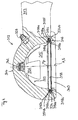
- FIG. 1 a first embodiment of a ball coupling according to the invention is generally designated 10.
- the ball coupling 10 and 10 comprises a coupling socket 12, which is formed integrally with a drawbar 13 with this. It further comprises a coupling ball 14, which is inserted into a part-spherical coupling recess 15 of the coupling socket 12.
- An abutment portion 20 of the coupling ball 14 is applied to a counter-contact area 22 of the coupling socket 12 and thus forms in the in FIG. 1 illustrated coupling state a clutch system area 24th
- the coupling axis A contains the center Mk of the coupling ball 14 and the center Mp of the coupling recess 15 and passes through the part-spherical coupling recess 15 centrally.
- annular groove 16 is formed, which is also centrally penetrated by the coupling axis A.
- the annular groove 16 is located in a direction orthogonal to the coupling axis A level.
- the annular groove 16 has two spaced-apart, substantially parallel axial boundary wall sections 16a and 16b which bound the annular groove 16 in the axial direction, and comprises a radial boundary wall section 16c located in the axial direction between the boundary wall sections 16a and 16b Ring groove 16 bounded radially outward.
- a seal 18 in the form of an O-ring such recorded that this is applied under axial compression deformation at the axial boundary wall portions 16 a and 16 b.
- the O-ring 18 may also be received with axial clearance in the annular groove.
- the O-ring 18 is sealingly against the surface of the coupling ball 14, on the side facing away from the coupling socket 12 hemisphere portion 19th
- annular gap 34 between the outer diameter of the O-ring 18 and the radial boundary wall portion 16c, which is in the in FIG. 1 shown example over the circumference of the annular groove 16 is formed uniformly.
- An annular gap section 34a can be seen on the side of the ball coupling remote from the drawbar and an annular gap section 34b, which is substantially the same size in the radial direction, on the drawbar side of the ball coupling.
- This annular gap 34 is fluid-filled, ie filled with ambient air or / and with lubricant, in particular lubricating grease.
- the floating bearing seal 18 may therefore, if necessary, move in the radial direction in the annular groove 16 relative to the female coupling socket 12 receiving it.
- the counter-contact area 22 of the coupling ball 12 has a recess 26 which serves as a grease reservoir. Via a grease nipple 28 provided in the coupling socket 12, lubricating grease can be pressed in between the contact region 20 and the counter-contact region 22, in particular into the depression 26.
- FIG. 2 a second embodiment of a ball coupling according to the invention is shown.
- the same components as in the first embodiment are denoted by the same reference numerals in the second embodiment but increased by the number 100.
- the second embodiment will be described only insofar as it differs from the first embodiment. Otherwise, reference is expressly made to the above description of the first embodiment.
- the second embodiment is different from that in FIG. 1 shown only in that the seal 118 of the second embodiment is a stamped sealing ring which is punched out of a sealing material layer.
- FIG. 3 a third embodiment of a ball coupling according to the invention is shown.
- the same components as in the first and second embodiments are shown in FIG. 3 provided with the same reference numerals, but increased by the number 200 or 100.
- the in FIG. 3 illustrated third embodiment is explained in the following only insofar as it differs from the first two embodiments, whose detailed explanation otherwise expressly referenced.
- the seal 218 of FIG. 3 is a seal produced by spray technology.
- the ball coupling 210 is shown after a long period of operation, so that due to material abrasion of the contact area 220 and the counter-investment area 222 have no more matching diameter, which means that when a relative tensile force in the direction of arrow 230 between the coupling ball 214 and the coupling socket 212th acts, the two coupling elements lie along a smaller compared to the previously shown embodiments Kupplungsstrom Anlagen Schemes 224 and a gap 232 between the contact area 220 and the counter-investment area 222 consists.
- the coupling system area 224 is in this case a Schmiegezone in which the contact area 220 and the counter-investment area 222 due to their very similar despite the wear diameter diameter abut one another.
- the centers Mk of the coupling ball 214 and Mp of the coupling socket 212 fall apart.
- the seal 218 is selected with its dimensions, in particular its opening diameter in the undeformed state, your sealing material and their sealing location on the coupling ball 214 so that grease, which is filled through the lubricating nipple 228 between the coupling ball 214 and the coupling socket 212, from the seal 218th
- the incoming grease may possibly displace existing between the coupling ball 214 and the coupling socket 212 existing air over the seal 218 away into the environment.
- this dimensioning of the seals applies to all embodiments shown in the present application.
- FIGS. 1 to 3 not shown is the possible inclusion of a meander spring or an elastomeric component in the annular gaps 34, 134 and 234, which ensures a centering of the respective seal 18, 118 and 218 with respect to the coupling axis A.
- FIG. 4 a ball socket of a fourth embodiment of a ball coupling according to the invention is shown.
- FIG. 4 The embodiment shown is explained only insofar as it differs from the preceding embodiments. Same components as in the embodiments of FIGS. 1 to 3 are given the same reference numerals but increased by the number 300 with respect to the first embodiment in FIG. 1 to the number 200 with respect to the second embodiment in FIG. 2 and increased by the number 100 with respect to the third embodiment in FIG. 3 , For a detailed description of the already known components is expressly to the description of FIGS. 1 to 3 directed.
- a central axis S of the circumferential elastomeric seal arranged in the annular groove 316 coincides with the coupling axis A. This applies if the seal 318, as in FIG. 4 shown, centered in the annular groove 316 is received, but this is due to the floating mounting of the seal 318 in the annular groove 316 random.
- the center axis S of the seal 318 is a rotational symmetry axis of the seal 318.
- the cross-sectional plane of the in FIG. 4 illustrated cross-section includes the central axis S of the seal 318 and lies in the plane of FIG. 4 ,
- the seal 318 comprises, when viewing the cross section of FIG. 4 , a sealing body 318a and a sealing lip 318a projecting from the sealing body 318a as a sealing lip.
- the end face 318c of the seal 318 facing the mouth 340 of the coupling recess 315 in the axial direction goes continuously from the sealing body 318a to the sealing area 318b over. Therefore, in the in FIG. 4 shown embodiment, the sealing region 318b from the sealing body 318a at the muzzle closer axial end thereof.
- the Abstehraum the sealing portion 318b has in each cross-section, the cross-sectional plane containing the central axis S, an extension component in the radial direction to the central axis S out and in the axial direction of the mouth 340 away, ie in the coupling recess 315 inside. This extension direction facilitates the placement of in FIG. 4 shown coupling socket 312 on a coupling ball, not shown considerably.
- the wall 318d defining the sealing body 318a is conically formed radially inward, namely with the mouth 340 of the coupling recess 315 widening opening angle. This means that the radial thickness of the sealing body 318a decreases in the axial direction from its mouth-remote end face 318e to its mouth-facing end face 318c.
- boundary wall 318f bounding the sealing body 318a and thus the seal 318 radially outward is essentially cylindrical with respect to the center axis S of the seal 318.
- the axial thickness of the seal 318 in the unloaded state ie the axial distance of the two end faces 318c and 318e is slightly smaller than the axial distance of the two Axialbegrenzungs vom 316a and 316b of the radial groove 316, so that the seal 318 in the radial groove 316 with slight axial play is already displaced by very small forces acting in the radial direction in just this direction.
- the sealing region 318b lies with its remote from the sealing body 318a Longitudinal end in the coupling state on the coupling ball on.
- valve 342 through which lubricant introduced into the clutch engagement region 322 via the grease nipple 328 can exit to lubricate a holddown engagement region 344 of the ball clutch.
- the valve 342 passes only a flow of lubricant from the coupling recess 315 to the hold-down abutment region 344 and blocks in the opposite flow direction.
- the annular gap 334 is in the in FIG. 4 Example shown either filled with air or partially or completely filled with a by the grease nipple 328 in the clutch system area 322 lubricant, in particular grease filled.
- the in the FIGS. 5a to 6b The seal 418 shown is explained only insofar as it differs from the one in FIG FIG. 4 shown seal 318, whose description is otherwise expressly referenced. Same components and component sections as in FIG. 4 are in the FIGS. 5a to 6b with the same reference numerals as in FIG FIG. 4 provided, but increased by the number 100.
- the sealing region 418b projecting from the sealing body 418a as a sealing lip encloses an angle W with the plane of the tangential plane to the mouth-near end face 418c of the seal 418.
- the angle W is advantageously in a range between about 45 ° and about 70 °.
- radial channels 446 are formed on the muzzle remote end face. These radial passages lead from the radially inner boundary surface 418d to the radially outer boundary surface 418f and thus pass through the seal body 418a in the radial direction.
- a plurality of radial channels 446 are arranged distributed in the circumferential direction at the same distance from each other over the entire seal 418. The meaning of these radial channels 446 will be described below with reference to Figures 6a and 6b explained.
- both the radially inner boundary surface 418 d of the seal body 418 a and the radially outer boundary surface 418 f of the seal body 418 a are conical, namely the radially inner boundary surface 418 d with an opening angle, which in the assembled state of the seal 418 for Mouth 440 of a coupling recess 415 is tapered and in the case of the radially outer boundary surface 418f with an opening angle which widens towards the same mouth, so that the radial thickness of the seal body 418a from the muzzle remote (mündungsfernere face 418e) axial end, which formed as axial recesses radial passages 446, towards the muzzle closer axial end (muzzle closer end face 418c) increases towards.
- the radial channels 446 are formed at the position which has the smallest thickness, so that the radial channels 446 acting as flow channels offer the lowest possible flow resistance.
- the radial channels 446 connect the annular gap 434 with the region of the coupling recess 415.
- a lubricant introduced into the region of the coupling recess 415 which threatens to radially expand the seal 418 due to the pressure exerted on the radially inner boundary surface 418d and thereby impair its sealing effect, flows via the radial channels 446 into the annular gap 334. and thus provide a pressure equalization, which the unwanted radial expansion of the seal 418 prevented.
- the seal 418 thus always lies securely against the coupling ball 414.
- D is the outside diameter of the seal
- B0 is the thickness of the muzzle nearer axial end of the seal body 418a as measured from the radially outer edge thereof to the junction of the seal body 418a with the seal portion 418b extending therefrom.
- B1 denotes the thickness of the muzzle-distal axial end of the sealing body, measured from its radially outer edge until the transition of the muzzle-remote end face 418e of the sealing body 418a to its radially inner boundary surface 418d.
- H1 denotes the axial thickness of the sealing body 418a, measured from the mouth-near end face 418c of the sealing body 418a to its mouth-distant end face 418e.
- H2 denotes the axial thickness of the solid seal body 418a, measured from its muzzle-side end face 418c to the bottom of the radial passage 446.
- H3 designates the axial height of the longitudinal end of the sealing region 418b adjacent to the seal, via a tangential plane orthogonal to the central axis of the seal, to the mouth-near end face 418c of the sealing body 418a.
- W denotes the angle at which the sealing region 418b protrudes from the plane of the mouth-near end face 418c from the sealing body 418a. If the muzzle closer end face 418c is not flat, is to determine the angle W, a tangential to the center axis of the gasket tangential plane to the muzzle closer end side.
- H4 denotes the depth of the radial channel 446, so that H1 is composed of the sum of H2 and H4.
- W2 denotes the angle which the radially outer boundary surface 418f of the sealing body 418a in the cross-sectional view of FIG FIG. 6c with a parallel to the central axis of the seal tangent to the radially outer boundary of the seal body 418a includes.
- the axial depth of the radial passage 446 is about 15% to about 25% of the total axial height H1 of the seal body 418a.
Abstract
Description
Die vorliegende Erfindung betrifft eine Kugelkupplung zur Kupplung eines Zugfahrzeugs mit einem Nachlauffahrzeug, umfassend eine mit einem der Fahrzeuge: Zugfahrzeug oder Nachlauffahrzeug, verbundene oder verbindbare Kupplungskugel und eine mit dem jeweils anderen Fahrzeug verbundene oder verbindbare Kupplungspfanne, welche mit der Kupplungskugel kuppelbar ist, wobei genauer die Kupplungskugel einen konvexen Anlagebereich aufweist und die Kupplungspfanne in einer Kupplungsausnehmung einen konkaven Gegenanlagebereich aufweist, welche Bereiche im Kupplungszustand der Kugelkupplung unter Bildung eines Kupplungsanlagebereichs aneinander anliegen und zwischen welchen die Kupplungskugel und die Kupplungspfanne bei Entkupplung der Kugelkupplung trennbar sind, wobei ferner ein Kupplungselement: Kupplungspfanne oder Kupplungskugel, eine Dichtung trägt, welche im Kupplungszustand den Kupplungsanlagebereich gegen die Umgebung abdichtet.The present invention relates to a ball coupling for coupling a traction vehicle with a trailing vehicle, comprising a with one of the vehicles: tractor or trailer vehicle, connected or connectable coupling ball and connected to the other vehicle or connectable coupling socket, which is coupled to the coupling ball, more precisely the coupling ball has a convex abutment region and the coupling socket in a coupling recess has a concave counter contact area, which areas abut each other in the coupling state of the ball coupling to form a Kupplungsanlagebereichs and between which the coupling ball and the coupling socket are disconnected during disengagement of the ball coupling, further comprising a coupling element: coupling socket or coupling ball, carries a seal which seals the clutch engagement area against the environment in the coupling state.
Eine derartige Kugelkupplung ist aus der
Es ist daher Aufgabe der vorliegenden Erfindung, eine gattungsgemäße Kugelkupplung mit gegenüber dem Stand der Technik erhöhter Standfestigkeit bereitzustellen.It is therefore an object of the present invention, a generic ball coupling with respect to the prior art increased stability provide.
Diese Aufgabe wird erfindungsgemäß durch eine Kugelkupplung der eingangs genannten Art gelöst, bei welcher die Dichtung, bezogen auf eine im Kupplungszustand den Mittelpunkt der Kupplungskugel enthaltende und die Kupplungsausnehmung der Kupplungspfanne im Wesentlichen zentral durchsetzende Kupplungsachse, mit radialem Bewegungsspiel in dem sie tragenden Kupplungselement aufgenommen ist. Durch eine derartige Ausgestaltung der Kugelkupplung kann sich die Dichtung bei betriebsbedingter Verlagerung der Kupplungselemente relativ zueinander und damit einhergehender Veränderung ihres Anlagezustands an dem sie nicht tragenden Kupplungselement, etwa durch Materialabrieb an der Kupplungskugel oder/und der Kupplungspfanne, aufgrund des radialen Bewegungsspiels relativ zur dem sie tragenden Kupplungselement bewegen, was eine unerwünscht hohe Betriebslast auf die Dichtung sowie ein unerwünschtes Abheben des Kupplungselements von der Dichtung vermeidet. Die Dichtung, welche zur Sicherstellung ihrer Dichtungswirkung unter Eigenvorspannung an dem sie nicht tragenden Kupplungselement anliegt, kann somit über sehr lange Betriebsdauer mit im Wesentlichen konstanter Vorspannung und damit konstanter Dichtungswirkung im Kupplungszustand an dem sie nicht tragenden Kupplungselement anliegen.This object is achieved by a ball coupling of the type mentioned, in which the seal, based on a in the coupling state, the center of the coupling ball containing and the coupling recess of the coupling socket substantially centrally passing through the coupling axis, with radial movement play in which it carries the coupling element. By such an embodiment of the ball coupling, the seal can at operational displacement of the coupling elements relative to each other and concomitant change their investment state in the non-supporting coupling element, such as material abrasion on the coupling ball and / or the coupling socket, due to the radial movement relative to the game move supporting coupling element, which avoids an undesirably high operating load on the seal and an undesirable lifting of the coupling element of the seal. The seal, which is applied to ensure their sealing effect under self-bias on the non-supporting coupling element, thus can be applied over a very long period of operation with a substantially constant bias and thus constant sealing effect in the coupling state on the non-supporting coupling element.
"Dichtung" im Sinne der vorliegenden Anmeldung bezeichnet einen Dichtungskörper, welcher stabil an dem die Dichtung aufnehmenden Kupplungselement halterbar ist und an welchem ein Dichtungsbereich vorgesehen ist, der zur Anlage an dem jeweils anderen Kupplungselement ausgebildet ist. Der Dichtungsbereich kann nur ein Oberflächenabschnitt des Dichtungskörpers sein, etwa bei einer O-Ring-Dichtung, oder kann eine am Dichtungskörper vorgesehene, vorzugsweise von diesem abstehende Dichtungsgeometrie, wie etwa eine Dichtlippenanordnung sein. Wenn in dieser Anmeldung ausgesagt ist, dass die Dichtung an einem Kupplungselement anliegt, so ist damit die Anlage des Dichtungsbereiches an diesem bezeichnet."Seal" in the sense of the present application refers to a sealing body, which is stably held on the coupling element receiving the seal and on which a sealing region is provided, which is designed to rest on the respective other coupling element. The sealing area may be only a surface portion of the seal body, such as an O-ring seal, or may be a sealing geometry provided on the seal body, preferably protruding therefrom, such as a sealing lip arrangement. If it is stated in this application that the seal bears against a coupling element, so that the system of the sealing region is designated at this.
Die oben genannte Kupplungsachse dient als Koordinatensystem zur Definition einer axialen und einer radialen Richtung sowie einer Umfangsrichtung. Mit "Kupplungsausnehmung" der Kupplungspfanne ist dabei jene Ausnehmung bezeichnet, in welche die Kupplungskugel beim Herstellen des Kupplungszustands, das heißt beim Ankuppeln, eingeführt wird, bis Anlagefläche und Gegenanlagefläche aneinander anliegen. Daher ist die Kupplungsausnehmung üblicherweise zumindest abschnittsweise sphärisch. Die Kupplungsachse sollte daher in einem idealisierten Kupplungszustand, etwa mit unverschlissenen Kupplungselementen bei Geradeausfahrt auf ebener horizontaler Fahrbahn, betrachtet werden. In diesem idealisierten Kupplungszustand enthält die Kupplungsachse den Mittelpunkt der Kupplungskugel, enthält ferner den Mittelpunkt des sphärischen Abschnitts der Kupplungsausnehmung der Kupplungspfanne und verläuft im Wesentlichen orthogonal zur Fahrbahnoberfläche.The above-mentioned coupling axis serves as a coordinate system for defining an axial and a radial direction and a circumferential direction. With "coupling recess" of the coupling socket while the recess is designated, in which the coupling ball during manufacture of the coupling state, that is, when coupling, is introduced, abut contact surface and counter-bearing surface to each other. Therefore, the coupling recess is usually at least partially spherical. The clutch axle should therefore be viewed in an idealized condition, such as with un-worn coupling elements when driving straight ahead on a flat horizontal roadway. In this idealized coupling state, the coupling axis includes the center of the coupling ball, further includes the center of the spherical portion of the coupling recess of the coupling socket, and is substantially orthogonal to the road surface.
Zwar kann grundsätzlich daran gedacht sein, lediglich einen bestimmten Abschnitt zwischen Kupplungskugel und Kupplungspfanne gegen die Umgebung abzudichten. Bevorzugt ist als Dichtung jedoch eine umlaufende Dichtung verwendet, so dass der Kupplungsanlagebereich möglichst vollständig gegen Umwelteinflüsse abgeschirmt ist.Although it can basically be thought to seal only a certain section between coupling ball and coupling socket against the environment. Preferably, however, a circumferential seal is used as the seal, so that the clutch contact area is shielded as completely as possible against environmental influences.
Die umlaufende Dichtung kann in einem besonders einfachen, auf Grund seiner hohen Dichtungswirkung jedoch auch bevorzugten Fall durch einen O-Ring gebildet sein. Ebenso ist jedoch denkbar, eine umlaufende Dichtung durch Heraustrennen eines Abschnitts aus einer Dichtungsmateriallage zu erhalten, etwa in an sich bekannter Weise durch Stanzen eines Dichtungsrings aus einer Dichtungsmateriallage. Ebenso kann der Dichtungsring durch einen Urformvorgang, etwa durch Spritzformen beziehungsweise Spritzgießen, erhalten werden.The peripheral seal may be formed in a particularly simple, but due to its high sealing effect, but also preferred case by an O-ring. However, it is also conceivable to obtain a peripheral seal by separating a section from a sealing material layer, for example in a manner known per se by punching a sealing ring from a sealing material layer. Likewise, the sealing ring can be obtained by a primary molding process, such as injection molding or injection molding.
Besonders vorteilhaft kann die umlaufende Dichtung in dem sie tragenden Kupplungselement in einer ringförmigen Aufnahmeausnehmung aufgenommen sein. Dabei kann eine ausreichende Dichtungswirkung gegenüber dem die Dichtung tragenden Kupplungselement durch axiale Verformung der Dichtung in der ringförmigen Aufnahmeausnehmung bereitgestellt werden. Bevorzugt ist die Dichtung jedoch mit axialem Spiel in der Aufnahmeausnehmung aufgenommen, um ihre Beweglichkeit im radialer Richtung zu sichern, da die Dichtung lediglich als Schmutzdichtung ausreicht und es dann auf die Dichtungswirkung gegenüber dem die Dichtung tragenden Kupplungselement nicht so sehr ankommt wie auf die Dichtungswirkung gegenüber dem jeweils anderen Kupplungselement.Particularly advantageously, the circumferential seal can be accommodated in the coupling element carrying it in an annular receiving recess. In this case, a sufficient sealing effect against the the seal-carrying coupling element can be provided by axial deformation of the seal in the annular receiving recess. Preferably, however, the seal is received with axial play in the receiving recess to ensure their mobility in the radial direction, since the seal is sufficient only as a dirt seal and then it does not depend on the sealing effect against the seal-carrying coupling element as much as on the sealing effect the other coupling element.
Grundsätzlich kann daran gedacht sein, dass axial zwischen die Aufnahmeausnehmung in axialer Richtung begrenzenden Axial-Begrenzungswandabschnitten Zwischenbauteile angeordnet sind, an welchen die Dichtung Anliegen kann. Aus Gründen einer möglichst geringen Bauteileanzahl ist es jedoch bevorzugt, wenn die Dichtung an wenigstens einer, besonders bevorzugt an beiden die Aufnahmeausnehmung in axialer Richtung begrenzenden Axial-Begrenzungswandabschnitten anliegt oder diesen, zur Erleichterung der Radialbeweglichkeit der Dichtung gegebenenfalls mit axialem Spiel, unmittelbar gegenüberliegt.In principle, it can be thought of that axially between the receiving recess in the axial direction limiting axial boundary wall sections intermediate components are arranged, to which the seal concerns. For reasons of the smallest possible number of components, however, it is preferred if the seal is applied to at least one, more preferably on both the receiving recess in the axial direction limiting Axial Begrenzungswandabschnitten or this, to facilitate the radial movement of the seal optionally with axial play, directly opposite.
Gemäß einer möglichen Ausführungsform der Erfindung kann die Aufnahmeausnehmung in der Kupplungskugel ausgebildet sein, wobei dann zur Bereitstellung des radialen Bewegungsspiels der Durchmesser des die Aufnahmeausnehmung in radialer Richtung begrenzenden Radial-Begrenzungswandabschnitts kleiner ist als die lichte Weite der Durchgangsöffnung der in die Aufnahmeausnehmung eingelegten umlaufenden Dichtung. Dabei ist die eingelegte Dichtung im Kupplungszustand, also in ihrem Zustand axialer Verformung bei Anlage an dem sie nicht tragenden Kupplungselement zu betrachten, da in der Regel eine axiale Kompression der Dichtung unvermeidbar zu einer radialen Verformung der Dichtung führt, und zwar derart, dass die lichte Weite der Durchgangsöffnung kleiner ist als im axial unverformten Zustand.According to a possible embodiment of the invention, the receiving recess may be formed in the coupling ball, then for providing the radial play of movement, the diameter of the receiving recess in the radial direction limiting radial boundary wall portion is smaller than the inside diameter of the passage opening of the inserted into the receiving recess circumferential seal. In this case, the inserted seal in the coupling state, ie in its state of axial deformation when it rests against the non-supporting coupling element, since usually an axial compression of the seal inevitably leads to a radial deformation of the seal, in such a way that the light Width of the passage opening is smaller than in the axially undeformed state.
Gemäß einer weiteren, gegenüber der zuvor genannten bevorzugten Ausführungsform, kann die Aufnahmeausnehmung in der Kupplungspfanne ausgebildet sein, wobei dann zur Sicherstellung des radialen Bewegungsspiels der Dichtung der Durchmesser des die Aufnahmeausnehmung in radialer Richtung begrenzenden Radial-Begrenzungswandabschnitts größer ist als der Außendurchmesser der in die Aufnahmeausnehmung eingelegten Dichtung. Wiederum ist aus den oben genannten Gründen die eingelegte Dichtung in ihrem axialen Verformungszustand unter Anlage an dem sie nicht tragenden Kupplungselement zu betrachten. In der hier beschriebenen Ausführungsform ist die Durchgangsöffnung der umlaufenden Dichtung von der Kupplungskugel durchsetzt, an welcher die Dichtung dichtend anliegt.According to another, compared to the aforementioned preferred embodiment, can be formed in the coupling socket, the receiving recess, in which case to ensure the radial play of movement of the seal, the diameter of the receiving recess defining in the radial direction radial boundary wall portion is greater than the outer diameter of the inserted into the receiving recess seal. Again, for the reasons stated above, the inserted gasket is to be considered in its axial deformation state under contact with the coupling element which does not carry it. In the embodiment described here, the passage opening of the peripheral seal is penetrated by the coupling ball, on which the seal rests sealingly.
In der oben bezeichneten Aufnahmeausnehmung kann die Dichtung schwimmend aufgenommen sein, d.h. die Dichtung ist - abgesehen von Reibungskräften - in radialer Richtung kräftefrei, insbesondere vorspannungsfrei, in der Aufnahmeausnehmung aufgenommen. Ein radial zwischen der Dichtung und dem Radialbegrenzungswandabschnitt der Aufnahmeausnehmung vorhandener Spaltraum, vorzugsweise Ringspaltraum, ist also abgesehen von betriebsbedingt möglicherweise entstehenden geringfügigen und hier nicht interessierenden Schmutzablagerungen im Wesentlichen frei von weiteren Bauteilen und somit im Wesentlichen fluidgefüllt, etwa schmierstoffgefüllt, insbesondere öl- oder/und fettgefüllt, oder/und gas-, insbesondere luftgefüllt.In the above-mentioned receiving recess, the seal may be floatingly received, i. the seal is - apart from frictional forces - free of forces in the radial direction, in particular free of tension, received in the receiving recess. A radially between the seal and the Radialbegrenzungswandabschnitt the receiving recess existing gap, preferably annular gap space is thus apart from operational possibly resulting minor and not interesting dirt deposits substantially free of other components and thus substantially fluid-filled, such as lubricant-filled, especially oil and / or fat-filled, and / or gas, in particular air-filled.
Eine besonders leistungsfähige Abdichtung des Kupplungsanlagebereichs gegen den Eintritt von Schmutz von außen in diesen kann bei an der Kupplungspfanne aufgenommener Dichtung dadurch erreicht werden, dass der zuvor genannte Dichtungsbereich, bei Betrachtung eines Querschnitts der Dichtung in einem an der Kupplungspfanne angeordneten, unbelasteten entkuppelten Zustand in einer, eine Mittelachse der umlaufenden Dichtung enthaltenden Schnittebene, von dem Dichtungskörper weg als Dichtlippe absteht, und zwar mit einer Erstreckungskomponente in radialer Richtung zur Mittelachse hin sowie mit einer Erstreckungskomponente in axialer Richtung von einer Mündung der Kupplungsausnehmung der Kupplungspfanne weg. Gerade die Erstreckungskomponente in axialer Richtung von der Mündung der Kupplungspfanne weg sorgt für eine schonende Möglichkeit, die Kupplungspfanne zur Herstellung einer Kupplungsverbindung unter größtmöglicher Schonung der Dichtung auf die Kupplungskugel aufzusetzen. Dabei liegt der Dichtungsbereich bei hergestelltem Kupplungszustand sehr gut an der Kupplungskugel an. Als "Mündung" der Kupplungspfanne ist in dieser Anmeldung der sich zur Umgebung hin öffnende Randbereich der Kupplungsausnehmung bezeichnet. Beim Ankuppeln wird also die Kupplungskugel durch die Mündung der Kupplungspfanne in deren Kupplungsausnehmung eingeführt.A particularly efficient sealing of the clutch contact area against the entry of dirt from the outside in these can be achieved in recorded on the coupling socket seal that the aforementioned sealing area, viewed in a arranged on the coupling socket, unloaded uncoupled state in a a cutting plane containing a central axis of the peripheral seal, protrudes from the sealing body as a sealing lip, with an extension component in the radial direction to the central axis and with an extension component in the axial direction of an opening of the coupling recess of the coupling socket path. Especially the extension component in the axial direction of the mouth of the coupling socket away provides a gentle way to set up the coupling socket for producing a coupling connection with the greatest possible protection of the seal on the coupling ball. In this case, the sealing area is very good at the coupling ball produced at the coupling state. As the "mouth" of the coupling socket, the edge region of the coupling recess which opens towards the environment is designated in this application. When coupling so the coupling ball is inserted through the mouth of the coupling socket in the coupling recess.
Im Kupplungszustand fällt üblicherweise die Mittelachse der umlaufenden Dichtung mit der zuvor genannten Kupplungsachse zusammen. Die Mittelachse kann jedoch auch unabhängig von anderen Bauteilen der Kugelkupplung ermittelt werden: es handelt sich dabei in der Regel um die Symmetriemittelachse der umlaufenden Dichtung.In the coupling state usually coincides the central axis of the peripheral seal with the aforementioned coupling axis. However, the central axis can also be determined independently of other components of the ball coupling: it is usually about the symmetry center axis of the circumferential seal.
Eine möglichst standfeste Dichtung kann bei der hohen betriebsbedingten Last, die auf sie einwirkt, dadurch erhalten werden, dass der Dichtungsbereich in axialer Richtung näher bei dem mündungsnäheren Ende des Dichtungskörpers von diesem absteht. Vorteilhafterweise geht die mündungsnähere Stirnseite des Dichtungskörpers stufenlos in den Dichtungsbereich über. Hierdurch können unerwünschte, weil die Integrität der Dichtung gefährdende Spannungsspitzen in der Dichtung vermieden werden.The most stable possible seal can be obtained in the high operational load that acts on them, that the sealing area in the axial direction closer to the muzzle closer end of the seal body protrudes from this. Advantageously, the muzzle closer end face of the sealing body is steplessly in the sealing area over. This can be undesirable because the integrity of the seal hazardous voltage spikes in the seal can be avoided.
Eine besonders gute Beweglichkeit des als Dichtlippe abstehenden Dichtungsbereichs in radialer Richtung sowie in axialer Richtung kann dadurch sichergestellt werden, dass sich der Querschnitt des Dichtungskörpers in axialer Richtung zur Mündung der Kupplungspfanne hin oder von dieser weg zumindest abschnittsweise verjüngt. Diese Beweglichkeit erleichtert das Herstellen des Kupplungszustands, ohne dass eine Beschädigung der Dichtung zu besorgen wäre. Gemäß einer bevorzugten Ausführungsform kann eine für das Ankuppeln besonders günstige Beweglichkeit des Dichtungsbereichs bereitgestellt werden, indem eine radial innere Begrenzungsfläche des Dichtungskörpers bezogen auf die Mittelachse der Dichtung zumindest abschnittsweise, vorzugsweise ausgehend vom Dichtungsbereich in axialer Richtung konisch ausgebildet ist.A particularly good mobility of the sealing region protruding as a sealing lip in the radial direction and in the axial direction can be ensured by the fact that the cross section of the sealing body at least partially tapers in the axial direction towards the mouth of the coupling socket or away from it. This mobility facilitates making the coupling state without damaging the seal. According to a preferred embodiment, a particularly favorable for the coupling mobility of the sealing region be provided by a radially inner boundary surface of the seal body with respect to the central axis of the seal at least partially, preferably from the sealing region in the axial direction is conical.
Eine besonders hohe Festigkeit des Dichtungskörpers und damit eine hohe Standfestigkeit der Dichtung insgesamt kann dadurch sichergestellt sein, dass eine radial äußere Begrenzungsfläche des Dichtungskörpers bezogen auf die Mittelachse der Dichtung zumindest abschnittsweise, vorzugsweise vollständig zylindrisch ist.A particularly high strength of the seal body and thus a high stability of the seal as a whole can be ensured that a radially outer boundary surface of the seal body with respect to the central axis of the seal at least partially, preferably completely cylindrical.
Falls die Dichtung radial außen umgebend ein besonders großer Spaltraum gewünscht ist, kann dies dadurch erreicht werden, dass eine radial äußere Begrenzungsfläche des Dichtungskörpers bezogen auf die Mittelachse der Dichtung zumindest abschnittsweise, vorzugsweise vollständig konisch ist.If the seal surrounding a particularly large gap radially outer space is desired, this can be achieved in that a radially outer boundary surface of the seal body with respect to the central axis of the seal is at least partially, preferably completely conical.
Um zu verhindern, dass in den Kupplungsanlagebereich, etwa über einen an einem Kupplungselement vorgesehenen Schmiernippel, eingebrachtes Schmiermittel, insbesondere Schmierfett, die Dichtung aus ihrer dichtenden Anlage an ein Kupplungselement verdrängt und somit in ihrer Dichtungswirkung schwächt, kann vorgesehen sein, dass die Dichtung, insbesondere der Dichtungskörper, wenigstens einen Kanal, vorzugsweise eine Mehrzahl von Kanälen, aufweist, welcher die Dichtung in radialer Richtung durchsetzt. Dadurch kann Schmierstoff auch in den die Dichtung aufnehmenden Spaltraum gelangen und so für einen Druckausgleich der auf die Dichtung, insbesondere den Dichtungskörper, wirkenden Fluidkräfte sorgen:In order to prevent that in the clutch system area, for example via a lubricating nipple provided on a coupling element, lubricant, in particular lubricating grease, displaces the seal from its sealing engagement with a coupling element and thus weakens its sealing effect, it can be provided that the seal, in particular the sealing body, at least one channel, preferably a plurality of channels, which passes through the seal in the radial direction. As a result, lubricant can also get into the gap receiving the seal and thus ensure a pressure equalization of the forces acting on the seal, in particular the seal body, fluid forces:
Herstellungstechnisch besonders einfach können die Kanäle in der Dichtung, insbesondere im Dichtungskörper hergestellt werden, indem der wenigstens eine Kanal als axiale Vertiefung in einer der in axiale Richtung weisenden Stirnseiten ausgebildet ist.In terms of manufacturing technology, the channels in the seal, in particular in the sealing body, can be produced particularly simply by forming the at least one channel as an axial depression in one of the end faces pointing in the axial direction.
Dabei kann die auf die umlaufende Dichtung, insbesondere auf den Dichtungskörper, wirkende Kraft dann besonders schnell ausgeglichen werden, wenn eine Mehrzahl von Kanälen vorgesehen ist. Um über die Umfangsrichtung hinweg eine möglichst gleichmäßige Kraftausgleichswirkung bereitstellen zu können, sind die Kanäle vorteilhaft wenigstens zum Teil, vorzugsweise jedoch vollständig, in Umfangsrichtung mit im Wesentlichen gleichem Abstand voneinander angeordnet.In this case, on the circumferential seal, in particular on the seal body, acting force can be compensated particularly quickly when a plurality of channels is provided. In order to be able to provide as uniform a force compensation effect as possible over the circumferential direction, the channels are advantageously arranged at least in part, but preferably completely, in the circumferential direction with substantially the same distance from each other.
Da die Kanäle als Strömungskanäle dienen, kann der Strömungswiderstand des Kanals dadurch reduziert werden, dass der Kanal mit möglichst geringer Länge ausgebildet wird. Dies kann konstruktiv beispielsweise dadurch realisiert sein, dass der wenigstens eine Kanal oder die Mehrzahl von Kanälen in radialer Richtung, ohne wesentliche Erstreckungskomponente in Umfangsrichtung oder in axialer Richtung verläuft.Since the channels serve as flow channels, the flow resistance of the channel can be reduced by forming the channel with the shortest possible length. This may be realized structurally, for example, by the fact that the at least one channel or the plurality of channels extends in the radial direction, without a substantial extension component in the circumferential direction or in the axial direction.
Bei Aufnahme der Dichtung in der Kupplungspfanne ist zur Sicherstellung der dichtenden Anlage der Dichtung an der Kupplungskugel bevorzugt, dass die Dichtung an der Oberfläche des von der Kupplungspfanne wegweisenden Halbkugelabschnitts der Kupplungskugel anliegt. Dann wirkt eine betriebsbedingte axiale Relativbewegung zwischen Kupplungspfanne und Kupplungskugel in der Regel Dichtungswirkung erhöhend, so dass sich die Kupplungspfanne im Kupplungszustand, etwa bei Überfahren von Bodenunebenheiten, in axialer Richtung lediglich von der Kupplungskugel geringfügig abheben, sich dieser jedoch nicht weiter annähern kann. Durch Abheben der Pfanne von der Kupplungskugel wird die wie oben beschrieben an der Kupplungskugel anliegende Dichtung zum Äquator der Kupplungskugel hin bewegt, was die Durchgangsöffnung der umlaufenden Dichtung weitet und so aufgrund der Materialelastizität des Dichtungsmaterials für eine Erhöhung der Anlagekraft der Dichtung an die Kupplungskugel sorgt.When receiving the seal in the coupling socket is preferred to ensure the sealing engagement of the seal on the coupling ball that the seal rests against the surface of the pointing away from the coupling socket hemisphere portion of the coupling ball. Then, an operational relative axial movement between coupling socket and coupling ball usually increases sealing effect, so that the coupling socket in the coupling state, about when driving over bumps in the axial direction only slightly from the coupling ball, but can not approach this further. By lifting the pan of the coupling ball as described above applied to the coupling ball seal is moved towards the equator of the coupling ball, which widens the passage opening of the circumferential seal and thus ensures due to the material elasticity of the sealing material for increasing the contact force of the seal to the coupling ball.
Weiterhin kann an einem der Kupplungselemente, bevorzugt an der Kupplungspfanne, ein Schmiernippel vorgesehen sein, mit welchem ein Schmierstoff, üblicherweise etwa Schmierfett, zwischen Kupplungspfanne und Kupplungskugel eingebracht werden kann. Dann ist es besonders bevorzugt, wenn die Dichtung zwar flüssigkeitsdicht, jedoch nicht gasdicht, an dem sie nicht tragenden Kupplungselement dichtend anliegt. Dadurch kann das Schmiermittel die zwischen Kupplungspfanne und Kupplungskugel vorhandene Luft in die Umgebung verdrängen, wird selbst jedoch durch die Dichtung zurückgehalten, so dass sie wie gewünscht zwischen Kupplungspfanne und Kupplungskugel verbleibt.Furthermore, a lubricating nipple may be provided on one of the coupling elements, preferably on the coupling socket, with which a lubricant, usually about grease, can be introduced between coupling socket and coupling ball. Then it is especially preferable Although the seal, although liquid-tight, but not gas-tight, on which it bears not sealing coupling element. As a result, the lubricant displace existing between coupling socket and coupling ball air into the environment, but is itself retained by the seal so that it remains as desired between the coupling socket and coupling ball.
Mit der in dieser Anmeldung bezeichneten "Dichtungswirkung" einer Kupplungsdichtung ist keine "Dichtungswirkung" im herkömmlichen Sinne gemeint, sondern im Wesentlichen eine Schmutz abweisende (Dichtungs-)Wirkung, die den unerwünschten Eintritt von Schmutz in den Kupplungsanlagebereich erheblich verringert, vorzugsweise vollständig vermeidet.The "sealing effect" of a coupling gasket referred to in this application does not mean a "sealing effect" in the conventional sense, but essentially a dirt-repellent (sealing) effect which substantially reduces, preferably completely avoids, the undesirable entry of dirt into the coupling installation region.
Zur Erhöhung der zwischen den Kupplungselementen einführbaren Schmierstoffmenge kann an der Oberfläche wenigstens eines der Kupplungselemente eine Vertiefung ausgebildet sein.To increase the amount of lubricant that can be introduced between the coupling elements, a depression can be formed on the surface of at least one of the coupling elements.
Weiterhin kann alternativ zur oben genannten schwimmenden Lagerung der Dichtung daran gedacht sein, zur Vermeidung einer Beschädigung der Dichtung bei der Herstellung des Kupplungszustandes, also beim Ankuppeln, die Dichtung derart in der Kugelkupplung anzuordnen bzw. auszubilden, dass eine zentrierende Vorspannkraft auf sie wirkt. Zur Realisierung dieser zentrierenden Vorspannkraft kann eine Federanordnung in der Kugelkupplung vorgesehen sein, welche die zentrierende Federkraft auf die Dichtung ausübt. Als besonders geeignet haben sich dabei Mäanderfedern oder Elastomerbauteile erwiesen. Diese Federanordnung, insbesondere die genannte Mäanderfeder, kann radial zwischen der Dichtung und einem Radial-Begrenzungswandabschnitt aufgenommen sein, welcher eine die Dichtung aufnehmende Aufnahmeausnehmung in radialer Richtung begrenzt. Dadurch kann vermieden werden, dass die Kugelkupplung zur Aufnahme der Federanordnung in axialer Richtung mit größeren Abmessungen ausgebildet werden muss. Darüber hinaus benötigt gerade eine Mäanderfeder sehr wenig Bauraum und kann bequem in Radialspalte mit geringer radialer Ausdehnung aufgenommen werden.Furthermore, as an alternative to the above-mentioned floating bearing of the seal to be thought of to avoid damage to the seal in the preparation of the coupling state, ie when coupling, the seal in the ball coupling or form such that a centering biasing force acts on them. To realize this centering biasing force, a spring arrangement may be provided in the ball coupling, which exerts the centering spring force on the seal. Meandering springs or elastomer components have proven to be particularly suitable. This spring arrangement, in particular the said meander spring, can be accommodated radially between the seal and a radial boundary wall section which delimits a receiving recess receiving the seal in the radial direction. This can be avoided that the ball coupling must be formed for receiving the spring assembly in the axial direction with larger dimensions. In addition, just a meander spring requires very little space and can be conveniently accommodated in radial gap with small radial expansion.
Die vorliegende Erfindung wird im folgenden anhand der beiliegenden Zeichnungen näher erläutert werden. Es stellt dar:
Figur 1- eine Querschnittsansicht einer ersten Ausführungsform einer er- findungsgemäßen unverschlissenen Kugelkupplung mit einem in der Kupplungspfanne aufgenommenen O-Ring,
Figur 2- eine Querschnittsansicht einer zweiten Ausführungsform einer erfindungsgemäßen unverschlissenen Kugelkupplung mit einem in der Kupplungspfanne aufgenommenen gestanzten Dichtungsring,
- Figur 3
- eine Querschnittsansicht einer dritten Ausführungsform einer er- findungsgemäßen Kugelkupplung mit Verschleißspuren mit einem in der Kupplungspfanne aufgenommenen gespritzten Dichtungs- ring,
- Figur 4
- eine Querschnittsansicht einer Kupplungspfanne einer vierten Ausführungsform einer erfindungsgemäßen Kugelkupplung mit schwimmend gelagertem Dichtungsring,
- Figur 5a
- eine Querschnittsansicht einer bevorzugten Dichtung für eine er- findungsgemäße Kugelkupplung,
- Figur 5b
- die Dichtung von
Figur 5a in der Draufsicht aus Richtung des Pfeils Vb, - Figur 6a
- die in den
Figuren 5a und 5b dargestellte Dichtung in eine Kugel- pfanne schwimmend eingesetzt, im unbelasteten, entkuppelten Zustand, - Figur 6b
- die gleiche Ansicht wie in
Figur 6a , jedoch während eines Ankup- pelvorgangs, und - Figur 6c
- die Dichtung von
Figur 5a in der gleichen Ansicht, jedoch verse- hen mit charakteristischen Abmessungen.
- FIG. 1
- 3 shows a cross-sectional view of a first embodiment of an unworn ball coupling according to the invention with an O-ring received in the coupling socket,
- FIG. 2
- a cross-sectional view of a second embodiment of an untapped ball coupling according to the invention with a received in the coupling socket punched sealing ring,
- FIG. 3
- 3 shows a cross-sectional view of a third embodiment of a ball coupling according to the invention with traces of wear, with a sprayed sealing ring accommodated in the coupling socket,
- FIG. 4
- a cross-sectional view of a coupling socket of a fourth embodiment of a ball coupling according to the invention with floating sealing ring,
- FIG. 5a
- FIG. 2 a cross-sectional view of a preferred seal for a ball coupling according to the invention, FIG.
- FIG. 5b
- the seal of
FIG. 5a in the plan view from the direction of the arrow Vb, - FIG. 6a
- in the
FIGS. 5a and 5b used seal floating in a ball socket, in the unloaded, uncoupled state, - FIG. 6b
- the same view as in
FIG. 6a but during a coupling process, and - FIG. 6c
- the seal of
FIG. 5a in the same view, but with characteristic dimensions.
In
Die Kupplungsachse A enthält den Mittelpunkt Mk der Kupplungskugel 14 sowie den Mittelpunkt Mp der Kupplungsausnehmung 15 und durchsetzt die teilsphärische Kupplungsausnehmung 15 zentral. Die Kupplungsachse A in den in den
In der Kupplungspfanne 12 ist eine Ringnut 16 ausgebildet, welche von der Kupplungsachse A ebenfalls zentral durchsetzt ist. Die Ringnut 16 liegt in einer zur Kupplungsachse A orthogonalen Ebene. Die Ringnut 16 weist zwei einander mit Abstand gegenüberliegende, im Wesentlichen parallele Axial-Begrenzungswandabschnitte 16a und 16b auf, welche die Ringnut 16 in axialer Richtung begrenzen, und umfasst einen in axialer Richtung zwischen den Begrenzungswandabschnitten 16a und 16b gelegenen Radial-Begrenzungswandabschnitt 16c, welcher die Ringnut 16 nach radial außen begrenzt. In der Ringnut 16 ist eine Dichtung 18 in Form eines O-Rings derart aufgenommen, dass dieser unter axialer Druckverformung an den Axial-Begrenzungswandabschnitten 16a und 16b anliegt. Der O-Ring 18 kann auch mit axialem Spiel in der Ringnut aufgenommen sein.In the
Ebenso liegt der O-Ring 18 dichtend an der Oberfläche der Kupplungskugel 14 an, und zwar an dem von der Kupplungspfanne 12 weg weisenden Halbkugelabschnitt 19.Similarly, the O-
Es ist in
Anzumerken ist, dass der Gegenanlagebereich 22 der Kupplungskugel 12 eine Vertiefung 26 aufweist, welche als Schmierfettspeicher dient. Über einen in der Kupplungspfanne 12 vorgesehenen Schmiernippel 28 kann Schmierfett zwischen den Anlagebereich 20 und den Gegenanlagebereich 22, insbesondere in die Vertiefung 26, eingepresst werden.It should be noted that the
In
Die zweite Ausführungsform unterscheidet sich von der in
In
Die Dichtung 218 von
In
Aufgrund der in radialer Richtung schwimmend gelagerten Dichtung 218 kann die Dichtung 218 die durch Materialabrieb im Kupplungszustand geänderten Relativpositionen der Kupplungselemente 212 und 214 durch eine radiale Relativbewegung relativ zur Ringnut 216 der Kupplungspfanne 212 ausgleichen, so dass eine zumindest lokal erhöhte Belastung der Dichtung 218 vermieden wird. In
Die Dichtung 218 ist mit ihren Abmessungen, insbesondere ihrem Öffnungsdurchmesser im unverformten Zustand, Ihrem Dichtungsmaterial und ihrem Dichtungsanlageort an der Kupplungskugel 214 so gewählt, dass Schmierfett, welches durch den Schmiernippel 228 zwischen die Kupplungskugel 214 und die Kupplungspfanne 212 eingefüllt wird, von der Dichtung 218 zurückgehalten wird, das eintretende Schmierfett jedoch eventuell zwischen der Kupplungskugel 214 und der Kupplungspfanne 212 vorhandene Luft über die Dichtung 218 hinweg in die Umgebung verdrängen kann. Diese Bemessung der Dichtungen gilt im Übrigen für alle in der vorliegenden Anmeldung dargestellten Ausführungsformen.The
In den
In
Die in
In der in
Die Mittelachse S der Dichtung 318 ist eine Rotationssymmetrieachse der Dichtung 318. Die Querschnittsebene des in
Die Dichtung 318 umfasst, bei Betrachtung des Querschnitts von
Die zur Mündung 340 der Kupplungsausnehmung 315 in axialer Richtung weisende Stirnseite 318c der Dichtung 318 geht stufenlos vom Dichtungskörper 318a zum Dichtungsbereich 318b über. Daher steht in dem in
Um den als Dichtlippe vom Dichtungskörper 318a abstehenden Dichtungsbereich 318b gerade beim Ankuppeln der Kupplungspfanne 312 an eine Kupplungskugel ausreichend Bewegungsmöglichkeit zu sichern, ist die den Dichtungskörper 318a nach radial innen begrenzende Wandung 318d konisch ausgebildet, und zwar mit einem sich zur Mündung 340 der Kupplungsausnehmung 315 hin aufweitenden Öffnungswinkel. Dies bedeutet, dass sich die radiale Dicke des Dichtungskörpers 318a in axialer Richtung von dessen mündungsfernerer Stirnseite 318e zu dessen mündungsnäherer Stirnseite 318c hin verringert.In order to ensure sufficient movement possibility for the sealing
Die den Dichtungskörper 318a und damit die Dichtung 318 nach radial außen begrenzende Begrenzungswand 318f ist dagegen bezogen auf die Mittelachse S der Dichtung 318 im Wesentlichen zylindrisch ausgebildet.On the other hand, the
Die axiale Dicke der Dichtung 318 im unbelasteten Zustand, also der axiale Abstand der beiden Stirnseiten 318c und 318e ist geringfügig kleiner als der axiale Abstand der beiden Axialbegrenzungsflächen 316a und 316b der Radialnut 316, so dass die Dichtung 318 in der Radialnut 316 mit geringfügigem axialen Spiel bereits durch sehr geringe in radialer Richtung wirkende Kräfte in eben dieser Richtung verschieblich ist.The axial thickness of the
Der Dichtungsbereich 318b liegt mit seinem vom Dichtungskörper 318a fernliegenden Längsende im Kupplungszustand an der Kupplungskugel an.The sealing
Es wird außerdem noch verwiesen auf ein Ventil 342, durch welches in den Kupplungsanlagebereich 322 über den Schmiernippel 328 eingeführtes Schmierfett austreten kann, um einen Niederhalteranlagebereich 344 der Kugelkupplung zu schmieren. Das Ventil 342 lässt nur eine Schmiermittelströmung von der Kupplungsausnehmung 315 zum Niederhalteranlagebereich 344 durch und sperrt in die entgegengesetzte Strömungsrichtung.Reference is also made to a
Der Ringspalt 334 ist in dem in
In
In
Überdies sind auf der mündungsferneren Stirnseite 418e der Dichtung 418 bzw. des Dichtungskörpers 418a Radialkanäle 446 ausgebildet. Diese Radialkanäle führen von der radial inneren Begrenzungsfläche 418d bis zur radial äußeren Begrenzungsfläche 418f und durchsetzen so den Dichtungskörper 418a in radialer Richtung.Moreover, 418e of the
Wie in
Weiterhin ist zu erkennen, das sowohl die radial innere Begrenzungsfläche 418d des Dichtungskörpers 418a als auch die radial äußere Begrenzungsfläche 418f des Dichtungskörpers 418a konisch ausgebildet sind, und zwar die radial innere Begrenzungsfläche 418d mit einem Öffnungswinkel, welcher sich im fertig montierten Zustand der Dichtung 418 zur Mündung 440 einer Kupplungsausnehmung 415 verjüngt und im Falle der radial äußeren Begrenzungsfläche 418f mit einem Öffnungswinkel, welcher sich zur selben Mündung hin aufweitet, so dass die radiale Dicke des Dichtungskörpers 418a vom mündungsferneren (mündungsfernere Stirnseite 418e) Axialende, welches die als axiale Vertiefungen ausgebildeten Radialkanäle 446 aufweist, zum mündungsnäheren Axialende (mündungsnähere Stirnseite 418c) hin zunimmt. Somit sind die Radialkanäle 446 an der Stelle ausgebildet, welche die geringste Dicke aufweist, so dass die als Strömungskanäle wirkenden Radialkanäle 446 einen möglichst geringen Strömungswiderstand bieten.Furthermore, it can be seen that both the radially
In den
Dabei ist zu erkennen, dass die Radialkanäle 446 den Ringspalt 434 mit dem Bereich der Kupplungsausnehmung 415 verbinden. Dadurch kann ein in den Bereich der Kupplungsausnehmung 415 eingebrachtes Schmiermittel, welches durch den von ihm auf die radial innere Begrenzungsfläche 418d ausgeübten Druck droht, die Dichtung 418 radial aufzuweiten und damit in ihrer Dichtungswirkung zu beeinträchtigen, über die Radialkanäle 446 in den Ringspalt 334 strömen, und so für einen Druckausgleich sorgen, welcher die unerwünschte radiale Aufweitung der Dichtung 418 verhindert. Die Dichtung 418 liegt somit stets sicher an der Kupplungskugel 414 an.It can be seen that the
Nachfolgend werden anhand der
Mit "D" ist der Außendurchmesser der Dichtung bezeichnet, mit "B0" die Dicke des mündungsnäheren axialen Endes des Dichtungskörpers 418a, gemessen von dessen radial äußerem Rand bis zum Übergang vom Dichtungskörper 418a zu dem von diesem abstehenden Dichtungsbereich 418b."D" is the outside diameter of the seal, "B0" is the thickness of the muzzle nearer axial end of the
Mit "B1" ist die Dicke des mündungsferneren axialen Endes des Dichtungskörpers bezeichnet, gemessen von dessen radial äußerem Rand bis zum Übergang der mündungsferneren Stirnseite 418e des Dichtungskörpers 418a zu dessen radial innerer Begrenzungsfläche 418d.The term "B1" denotes the thickness of the muzzle-distal axial end of the sealing body, measured from its radially outer edge until the transition of the muzzle-
Mit "H1" ist die axiale Dicke des Dichtungskörpers 418a bezeichnet, gemessen von der mündungsnäheren Stirnseite 418c des Dichtungskörpers 418a zu dessen mündungsfernerer Stirnseite 418e.The term "H1" denotes the axial thickness of the sealing
Mit "H2" ist die axiale Dicke des massiven Dichtungskörpers 418a bezeichnet, gemessen von dessen mündungsnäherer Stirnseite 418c bis zum Grund des Radialkanals 446.The term "H2" denotes the axial thickness of the
Mit "H3" ist die axiale Höhe des zur Dichtung anliegenden Längsendes des Dichtungsbereichs 418b über eine zur Mittelachse der Dichtung orthogonalen Tangentialebene an die mündungsnähere Stirnseite 418c des Dichtungskörpers 418a bezeichnet."H3" designates the axial height of the longitudinal end of the sealing
Mit "W" ist der Winkel bezeichnet, unter welchem der Dichtungsbereich 418b von der Ebene der mündungsnäheren Stirnseite 418c vom Dichtungskörper 418a absteht. Sofern die mündungsnähere Stirnseite 418c nicht eben ist, ist zur Ermittlung des Winkels W eine zur Mittelachse der Dichtung orthogonale Tangentialebene an die mündungsnähere Stirnseite heranzuziehen."W" denotes the angle at which the
Mit "H4" ist schließlich die Tiefe des Radialkanals 446 bezeichnet, so dass H1 sich aus der Summe von H2 und H4 zusammensetzt.Finally, "H4" denotes the depth of the
Mit "W2" ist der Winkel bezeichnet, welchen die radial äußere Begrenzungsfläche 418f des Dichtungskörpers 418a in der Querschnittsdarstellung von
Für diese charakteristischen Abmessungen gelten folgende bevorzugte Dimensionierungsvorschriften zur Erzielung besonders guter Dichtergebnisse:
- B0 beträgt etwa 8% bis 11 % des Durchmessers D.
- W beträgt etwa 45° bis etwa 70°.
- W2 beträgt etwa 10° bis etwa 20°.
- H1 beträgt etwa 5% bis etwa 8% des Durchmessers D.
- H3 beträgt etwa 70% bis 85% der axialen Gesamthöhe H1 des Dichtungskörpers 418a.
- B0 is about 8% to 11% of the diameter D.
- W is about 45 ° to about 70 °.
- W2 is about 10 ° to about 20 °.
- H1 is about 5% to about 8% of the diameter D.
- H3 is about 70% to 85% of the total axial height H1 of the
seal body 418a.
Die axiale Tiefe des Radialkanals 446 beträgt etwa 15% bis etwa 25% der axialen Gesamthöhe H1 des Dichtungskörpers 418a.The axial depth of the
Es wird ausdrücklich darauf hingewiesen, dass jedes technische Merkmal, welches lediglich in einer Ausführungsform der
Die Anmelderin behält sich vor, jeweils gesonderten Schutz für die in dieser Anmeldung dargestellten und beschriebenen Dichtungen zu beanspruchen.The Applicant reserves the right to claim separate protection for the seals shown and described in this application.
Claims (17)
- A ball coupling for coupling a towing vehicle to a trailer vehicle, comprising a coupling ball (14;114;214;414) which is connected or can be connected to one of the vehicles: towing vehicle or trailer vehicle, and a coupling socket (12;112;212;312;412) which is connected or can be connected to the respective other vehicle and which can be coupled to the coupling ball (14;114;214; 414), wherein more precisely the coupling ball (14;114;214;414) has a convex contact area (20;120;220) and in a coupling recess (15;115;215;315;415) the coupling socket (12;112;212;312;412) has a concave opposite-contact area (22;122;222;322), which in the coupled condition of the ball coupling bear against one another to form a coupling contact area (24;124;224) and between which the coupling ball (14;114;214;414) and the coupling socket (12;112;212;312;412) can be separated when the ball coupling is uncoupled,
wherein further one coupling element: coupling socket (12;112;212;312;412) or coupling ball (14;114;214;414) has a seal (18;118;218;318;418) which in the coupled condition seals the coupling contact area (24;124;224) from the environment,
characterised in that, in relation to a coupling axis (A) which in the coupled condition contains the centre point of the coupling ball (14;114;214;414) and which passes substantially centrally through the coupling recess (15;115;215;315;415) of the coupling socket (12;112;212;312;412), the seal (18;118;218;318;418) is accommodated with radial play in the coupling element (12;112;212;312;412) carrying it. - A ball coupling according to Claim 1,
characterised in that the seal (18;118;218;318;418) is a circumferential seal (18;118;218;318;418). - A ball coupling according to Claim 2,
characterised in that the seal (18;118;218;318;418) comprises an O-ring (18). - A ball coupling according to one of Claims 2 to 3,
characterised in that the seal (18;118;218;318;418) comprises a sealing ring (218) formed by a forming process, preferably by injection moulding. - A ball coupling according to any one of the preceding Claims,
characterised in that the seal (18;118;218;318;418) comprises a seal body (318a;418a) which can be mounted on the coupling element (12;112;212;312;412) accommodating the seal (18;118;218;318;418), with a sealing area (318b;418b) provided thereon which is designed to bear against the respective other coupling element (12;112;212;312;412). - A ball coupling according to any one of Claims 2 to 5,
characterised in that the seal (18;118;218;318;418) is accommodated in an annular accommodating recess (16;116;216;316;416), preferably with axial deformation. - A ball coupling according to Claim 6,
characterised in that the seal (18;118;218;318;418) bears against at least one, preferably against both, boundary wall portions (16a,16b;116a,116b;216a,216b;316a,316b;416a,416b) bounding the accommodating recess (16;116;216) in an axial direction, or is situated directly opposite thereto with axial clearance. - A ball coupling according to Claim 6 or 7,
characterised in that the accommodating recess (16;116;216;316;416) is formed in the coupling socket (12;112;212;312;412), wherein the diameter of the boundary wall portion (16c;116c;216c;316c;416c) bounding the accommodating recess (16;116;216;316;416) in radial direction is greater than the outer diameter of the seal (18;118;218;318;418) inserted into the accommodating recess (16; 116; 216; 316; 416) . - A ball coupling according to Claims 8, with reference to Claims 2 and 5,
characterised in that, when viewing a cross-section of the seal (318;418) in an unloaded uncoupled condition arranged on the coupling socket (312;412) in a sectional plane containing the centre axis (S) of the circumferential seal (318;418), the sealing area (318b;418b) projects away from the seal body (318a;418a) as a sealing lip, that is with an extension component in a radial direction towards the centre axis (S) and also with an extension component in an axial direction away from the mouth (340;440) of the coupling socket (312;412). - A ball coupling according to Claim 9,
characterised in that the sealing area (318b;418b) projects in an axial direction closer to the end (at 318c; at 418c) nearer the mouth of the seal body (318a;418a) away from the latter. - A ball coupling according to any one of the preceding Claims,
characterised in that the seal (418), in particular the seal body (418a), has at least one channel (446), preferably a plurality of channels (446), which pass/passes through the seal (418) in a radial direction. - A ball coupling according to Claim 11,
characterised in that the at least one channel (446) is in form of an axial depression in one of the end faces (418e) of the seal (418) facing in an axial direction, in particular of the seal body (418a). - A ball coupling according to Claim 11 or 12, with reference to Claim 2,
characterised in that the circumferential seal (418) has a plurality of channels (446) which in a peripheral direction are arranged at least partly, preferably entirely, at substantially an equal distance from one another. - A ball coupling according to any one of the preceding Claims,
characterised in that the seal (18;118;218;318;418) is accommodated in the coupling socket (12;112;212;312;412) and bears against the surface of the hemispherical portion (19;119;219) of the coupling ball (14;114;214;414) facing away from the coupling socket (12;112;212; 312;412). - A ball coupling according to any one of the preceding Claims,
characterised in that the seal (18;118;218;318;418) accommodated in a coupling element (12;112;212;312;412) bears fluid-tightly but not gastightly against the respective other coupling element (14;114;214;414). - A ball coupling according to any one of the preceding Claims, with reference to Claim 6,
characterised in that the seal (18;118;218;318;418) is accommodated floating in the accommodating recess (16;116;216;316;416). - A ball coupling according to any one of Claims 1 to 15,
characterised in that a centring biasing force acts on the seal.
Priority Applications (1)
| Application Number | Priority Date | Filing Date | Title |
|---|---|---|---|
| PL08716636T PL2137015T3 (en) | 2007-04-10 | 2008-03-19 | Ball coupling comprising a seal accommodated to be relatively movable |
Applications Claiming Priority (2)
| Application Number | Priority Date | Filing Date | Title |
|---|---|---|---|
| DE102007016896A DE102007016896A1 (en) | 2007-04-10 | 2007-04-10 | Ball coupling with relatively movably received seal |
| PCT/EP2008/002218 WO2008122350A1 (en) | 2007-04-10 | 2008-03-19 | Ball coupling comprising a seal accommodated to be relatively movable |
Publications (2)
| Publication Number | Publication Date |
|---|---|
| EP2137015A1 EP2137015A1 (en) | 2009-12-30 |
| EP2137015B1 true EP2137015B1 (en) | 2011-05-18 |
Family
ID=39434246
Family Applications (1)
| Application Number | Title | Priority Date | Filing Date |
|---|---|---|---|
| EP08716636A Active EP2137015B1 (en) | 2007-04-10 | 2008-03-19 | Ball coupling comprising a seal accommodated to be relatively movable |
Country Status (9)
| Country | Link |
|---|---|
| EP (1) | EP2137015B1 (en) |
| AT (1) | ATE509790T1 (en) |
| AU (1) | AU2008235064B2 (en) |
| BR (1) | BRPI0810193B1 (en) |
| DE (1) | DE102007016896A1 (en) |
| PL (1) | PL2137015T3 (en) |
| RU (1) | RU2424914C1 (en) |
| WO (1) | WO2008122350A1 (en) |
| ZA (1) | ZA200906926B (en) |
Cited By (1)
| Publication number | Priority date | Publication date | Assignee | Title |
|---|---|---|---|---|
| RU2726486C1 (en) * | 2019-12-30 | 2020-07-14 | Федеральное государственное бюджетное образовательное учреждение высшего образования "Елецкий государственный университет им. И.А. Бунина" | Light weight road-train drawbar |
Families Citing this family (2)
| Publication number | Priority date | Publication date | Assignee | Title |
|---|---|---|---|---|
| AT513831B1 (en) * | 2013-04-09 | 2014-08-15 | Josef Ing Scharmüller | Hochlastzugöse |
| CN105757829A (en) * | 2016-01-24 | 2016-07-13 | 余姚市苏杰电器科技有限公司 | Vibration isolation type water cooling air conditioner outdoor unit |
Family Cites Families (8)
| Publication number | Priority date | Publication date | Assignee | Title |
|---|---|---|---|---|
| GB544759A (en) * | 1941-02-20 | 1942-04-27 | Carl Heimann | Ball joint |
| DE3502799A1 (en) * | 1984-07-11 | 1986-07-31 | Martin Merkel GmbH & Co KG, 2102 Hamburg | SHAFT SEAL |
| GB2251838B (en) * | 1991-01-16 | 1994-11-30 | Arthur Goddard | Vehicle coupling assembly |
| DE4411383A1 (en) * | 1993-05-20 | 1994-11-24 | Willimczik Wolfhart | Rotary lobe machines with a bearing-free piston engine |
| DE20116706U1 (en) * | 2001-10-11 | 2001-12-06 | Knott Gmbh | Train coupling with stabilizing device |
| US7134668B2 (en) * | 2001-10-24 | 2006-11-14 | Ebara Corporation | Differential pumping seal apparatus |
| AT412459B (en) * | 2002-06-03 | 2005-03-25 | Scharmueller Gmbh & Co Kg | CLUTCH DEVICE |
| DE102005022879A1 (en) | 2005-05-18 | 2006-11-23 | Jost-Werke Gmbh & Co. Kg | Ball coupling with sealed contact area |
-
2007
- 2007-04-10 DE DE102007016896A patent/DE102007016896A1/en not_active Withdrawn
-
2008
- 2008-03-19 BR BRPI0810193A patent/BRPI0810193B1/en not_active IP Right Cessation
- 2008-03-19 AT AT08716636T patent/ATE509790T1/en active
- 2008-03-19 WO PCT/EP2008/002218 patent/WO2008122350A1/en active Application Filing
- 2008-03-19 PL PL08716636T patent/PL2137015T3/en unknown
- 2008-03-19 EP EP08716636A patent/EP2137015B1/en active Active
- 2008-03-19 AU AU2008235064A patent/AU2008235064B2/en not_active Ceased
- 2008-03-19 RU RU2009141352/11A patent/RU2424914C1/en not_active IP Right Cessation
-
2009
- 2009-10-06 ZA ZA200906926A patent/ZA200906926B/en unknown
Cited By (1)
| Publication number | Priority date | Publication date | Assignee | Title |
|---|---|---|---|---|
| RU2726486C1 (en) * | 2019-12-30 | 2020-07-14 | Федеральное государственное бюджетное образовательное учреждение высшего образования "Елецкий государственный университет им. И.А. Бунина" | Light weight road-train drawbar |
Also Published As
| Publication number | Publication date |
|---|---|
| RU2009141352A (en) | 2011-05-20 |
| EP2137015A1 (en) | 2009-12-30 |
| AU2008235064B2 (en) | 2012-02-02 |
| AU2008235064A1 (en) | 2008-10-16 |
| RU2424914C1 (en) | 2011-07-27 |
| ATE509790T1 (en) | 2011-06-15 |
| DE102007016896A1 (en) | 2008-10-16 |
| ZA200906926B (en) | 2010-05-26 |
| WO2008122350A1 (en) | 2008-10-16 |
| BRPI0810193B1 (en) | 2019-09-10 |
| PL2137015T3 (en) | 2011-10-31 |
| BRPI0810193A2 (en) | 2014-12-30 |
Similar Documents
| Publication | Publication Date | Title |
|---|---|---|
| EP2631499B1 (en) | Ball joint | |
| DE60214212T2 (en) | HYDROELASTIC BALL JOINT | |
| EP2024653B1 (en) | Rolling bearing having two inner rings and a seal arrangement for sealing the parting joint between the inner rings | |
| EP0932774B1 (en) | Disc brake caliper | |
| DE102005029614A1 (en) | Bushing bearing with radial and / or axial stop and method for generating an axial stop in a bushing bearing | |
| WO2006056171A1 (en) | Joint arrangement and/or bearing arrangement | |
| EP1611367B1 (en) | Hydraulically damping rubber bush bearing for vertical mounting | |
| DE102014009046A1 (en) | Coupling part for a quick coupling for high pressure hydraulic lines | |
| DE60310346T2 (en) | Sealing plug for an opening in a component | |
| WO2014111215A1 (en) | Ball joint | |
| EP2137015B1 (en) | Ball coupling comprising a seal accommodated to be relatively movable | |
| WO2014012959A2 (en) | Brake master cylinder for a motor vehicle brake system with profiled pressure piston | |
| DE3244209A1 (en) | Seal for sealing against hydraulic fluids, preferably a sealing scraper element | |
| DE3016231C2 (en) | Sealing arrangement | |
| EP1162394B1 (en) | Seal element for hydraulic piston-cylinder arrangements | |
| DE102014017386A1 (en) | Spring function component for a hydroelastic bearing | |
| DE102004018054B4 (en) | bellows | |
| DE102009012366B4 (en) | Sealing element for a cylinder / piston arrangement of a vehicle brake system | |
| EP1386809A1 (en) | Master cylinder | |
| EP1138968A1 (en) | Labyrinth seal for a universal joint | |
| DE10083269B4 (en) | A ball bearing retainer | |
| DE102014208898A1 (en) | Slave cylinder for a hydraulic release system with piston centering | |
| DE102008033968A1 (en) | slave cylinder | |
| DE102019202130B4 (en) | Sealing arrangement | |
| DE102014009063A1 (en) | Coupling part for a quick coupling for high pressure hydraulic lines |
Legal Events
| Date | Code | Title | Description |
|---|---|---|---|
| PUAI | Public reference made under article 153(3) epc to a published international application that has entered the european phase |
Free format text: ORIGINAL CODE: 0009012 |
|
| 17P | Request for examination filed |
Effective date: 20091110 |
|
| AK | Designated contracting states |
Kind code of ref document: A1 Designated state(s): AT BE BG CH CY CZ DE DK EE ES FI FR GB GR HR HU IE IS IT LI LT LU LV MC MT NL NO PL PT RO SE SI SK TR |
|
| DAX | Request for extension of the european patent (deleted) | ||
| GRAP | Despatch of communication of intention to grant a patent |
Free format text: ORIGINAL CODE: EPIDOSNIGR1 |
|
| GRAS | Grant fee paid |
Free format text: ORIGINAL CODE: EPIDOSNIGR3 |
|
| GRAA | (expected) grant |
Free format text: ORIGINAL CODE: 0009210 |
|
| REG | Reference to a national code |
Ref country code: GB Ref legal event code: FG4D Free format text: NOT ENGLISH |
|
| REG | Reference to a national code |
Ref country code: CH Ref legal event code: EP Ref country code: CH Ref legal event code: NV Representative=s name: BOHEST AG |
|
| REG | Reference to a national code |
Ref country code: IE Ref legal event code: FG4D Free format text: LANGUAGE OF EP DOCUMENT: GERMAN |
|
| REG | Reference to a national code |
Ref country code: DE Ref legal event code: R096 Ref document number: 502008003591 Country of ref document: DE Effective date: 20110630 |
|
| REG | Reference to a national code |
Ref country code: NL Ref legal event code: T3 |
|
| REG | Reference to a national code |
Ref country code: SE Ref legal event code: TRGR |
|
| PG25 | Lapsed in a contracting state [announced via postgrant information from national office to epo] |
Ref country code: PT Free format text: LAPSE BECAUSE OF FAILURE TO SUBMIT A TRANSLATION OF THE DESCRIPTION OR TO PAY THE FEE WITHIN THE PRESCRIBED TIME-LIMIT Effective date: 20110919 Ref country code: HR Free format text: LAPSE BECAUSE OF FAILURE TO SUBMIT A TRANSLATION OF THE DESCRIPTION OR TO PAY THE FEE WITHIN THE PRESCRIBED TIME-LIMIT Effective date: 20110518 Ref country code: NO Free format text: LAPSE BECAUSE OF FAILURE TO SUBMIT A TRANSLATION OF THE DESCRIPTION OR TO PAY THE FEE WITHIN THE PRESCRIBED TIME-LIMIT Effective date: 20110818 |
|
| REG | Reference to a national code |
Ref country code: PL Ref legal event code: T3 |
|
| PG25 | Lapsed in a contracting state [announced via postgrant information from national office to epo] |
Ref country code: GR Free format text: LAPSE BECAUSE OF FAILURE TO SUBMIT A TRANSLATION OF THE DESCRIPTION OR TO PAY THE FEE WITHIN THE PRESCRIBED TIME-LIMIT Effective date: 20110819 Ref country code: CY Free format text: LAPSE BECAUSE OF FAILURE TO SUBMIT A TRANSLATION OF THE DESCRIPTION OR TO PAY THE FEE WITHIN THE PRESCRIBED TIME-LIMIT Effective date: 20110518 Ref country code: ES Free format text: LAPSE BECAUSE OF FAILURE TO SUBMIT A TRANSLATION OF THE DESCRIPTION OR TO PAY THE FEE WITHIN THE PRESCRIBED TIME-LIMIT Effective date: 20110829 Ref country code: FI Free format text: LAPSE BECAUSE OF FAILURE TO SUBMIT A TRANSLATION OF THE DESCRIPTION OR TO PAY THE FEE WITHIN THE PRESCRIBED TIME-LIMIT Effective date: 20110518 Ref country code: IS Free format text: LAPSE BECAUSE OF FAILURE TO SUBMIT A TRANSLATION OF THE DESCRIPTION OR TO PAY THE FEE WITHIN THE PRESCRIBED TIME-LIMIT Effective date: 20110918 Ref country code: SI Free format text: LAPSE BECAUSE OF FAILURE TO SUBMIT A TRANSLATION OF THE DESCRIPTION OR TO PAY THE FEE WITHIN THE PRESCRIBED TIME-LIMIT Effective date: 20110518 |
|
| REG | Reference to a national code |
Ref country code: IE Ref legal event code: FD4D |
|
| PG25 | Lapsed in a contracting state [announced via postgrant information from national office to epo] |
Ref country code: CZ Free format text: LAPSE BECAUSE OF FAILURE TO SUBMIT A TRANSLATION OF THE DESCRIPTION OR TO PAY THE FEE WITHIN THE PRESCRIBED TIME-LIMIT Effective date: 20110518 Ref country code: IE Free format text: LAPSE BECAUSE OF FAILURE TO SUBMIT A TRANSLATION OF THE DESCRIPTION OR TO PAY THE FEE WITHIN THE PRESCRIBED TIME-LIMIT Effective date: 20110518 |
|
| PG25 | Lapsed in a contracting state [announced via postgrant information from national office to epo] |
Ref country code: RO Free format text: LAPSE BECAUSE OF FAILURE TO SUBMIT A TRANSLATION OF THE DESCRIPTION OR TO PAY THE FEE WITHIN THE PRESCRIBED TIME-LIMIT Effective date: 20110518 Ref country code: DK Free format text: LAPSE BECAUSE OF FAILURE TO SUBMIT A TRANSLATION OF THE DESCRIPTION OR TO PAY THE FEE WITHIN THE PRESCRIBED TIME-LIMIT Effective date: 20110518 Ref country code: SK Free format text: LAPSE BECAUSE OF FAILURE TO SUBMIT A TRANSLATION OF THE DESCRIPTION OR TO PAY THE FEE WITHIN THE PRESCRIBED TIME-LIMIT Effective date: 20110518 |
|
| PLBE | No opposition filed within time limit |
Free format text: ORIGINAL CODE: 0009261 |
|
| STAA | Information on the status of an ep patent application or granted ep patent |
Free format text: STATUS: NO OPPOSITION FILED WITHIN TIME LIMIT |
|
| 26N | No opposition filed |
Effective date: 20120221 |
|
| REG | Reference to a national code |
Ref country code: DE Ref legal event code: R097 Ref document number: 502008003591 Country of ref document: DE Effective date: 20120221 |
|
| PG25 | Lapsed in a contracting state [announced via postgrant information from national office to epo] |
Ref country code: MC Free format text: LAPSE BECAUSE OF NON-PAYMENT OF DUE FEES Effective date: 20120331 |
|
| GBPC | Gb: european patent ceased through non-payment of renewal fee |
Effective date: 20120319 |
|
| REG | Reference to a national code |
Ref country code: FR Ref legal event code: ST Effective date: 20121130 |
|
| PG25 | Lapsed in a contracting state [announced via postgrant information from national office to epo] |
Ref country code: GB Free format text: LAPSE BECAUSE OF NON-PAYMENT OF DUE FEES Effective date: 20120319 Ref country code: FR Free format text: LAPSE BECAUSE OF NON-PAYMENT OF DUE FEES Effective date: 20120402 |
|
| PG25 | Lapsed in a contracting state [announced via postgrant information from national office to epo] |
Ref country code: BG Free format text: LAPSE BECAUSE OF FAILURE TO SUBMIT A TRANSLATION OF THE DESCRIPTION OR TO PAY THE FEE WITHIN THE PRESCRIBED TIME-LIMIT Effective date: 20110818 |
|
| PG25 | Lapsed in a contracting state [announced via postgrant information from national office to epo] |
Ref country code: MT Free format text: LAPSE BECAUSE OF FAILURE TO SUBMIT A TRANSLATION OF THE DESCRIPTION OR TO PAY THE FEE WITHIN THE PRESCRIBED TIME-LIMIT Effective date: 20110518 |
|
| PG25 | Lapsed in a contracting state [announced via postgrant information from national office to epo] |
Ref country code: LU Free format text: LAPSE BECAUSE OF NON-PAYMENT OF DUE FEES Effective date: 20120319 |
|
| REG | Reference to a national code |
Ref country code: CH Ref legal event code: PCAR Free format text: NEW ADDRESS: HOLBEINSTRASSE 36-38, 4051 BASEL (CH) |
|
| PG25 | Lapsed in a contracting state [announced via postgrant information from national office to epo] |
Ref country code: HU Free format text: LAPSE BECAUSE OF FAILURE TO SUBMIT A TRANSLATION OF THE DESCRIPTION OR TO PAY THE FEE WITHIN THE PRESCRIBED TIME-LIMIT Effective date: 20080319 |
|
| REG | Reference to a national code |
Ref country code: DE Ref legal event code: R082 Ref document number: 502008003591 Country of ref document: DE Representative=s name: RUTTENSPERGER LACHNIT TROSSIN GOMOLL PATENT- U, DE Ref country code: DE Ref legal event code: R082 Ref document number: 502008003591 Country of ref document: DE Representative=s name: RUTTENSPERGER LACHNIT TROSSIN GOMOLL, PATENT- , DE |
|
| PGFP | Annual fee paid to national office [announced via postgrant information from national office to epo] |
Ref country code: EE Payment date: 20150325 Year of fee payment: 8 Ref country code: LT Payment date: 20150302 Year of fee payment: 8 |
|
| PGFP | Annual fee paid to national office [announced via postgrant information from national office to epo] |
Ref country code: LV Payment date: 20150326 Year of fee payment: 8 |
|
| PGFP | Annual fee paid to national office [announced via postgrant information from national office to epo] |
Ref country code: BE Payment date: 20150318 Year of fee payment: 8 |
|
| PG25 | Lapsed in a contracting state [announced via postgrant information from national office to epo] |
Ref country code: BE Free format text: LAPSE BECAUSE OF NON-PAYMENT OF DUE FEES Effective date: 20160331 |
|
| REG | Reference to a national code |
Ref country code: LT Ref legal event code: MM4D Effective date: 20160319 |
|
| REG | Reference to a national code |
Ref country code: EE Ref legal event code: MM4A Ref document number: E005657 Country of ref document: EE Effective date: 20160331 |
|
| PG25 | Lapsed in a contracting state [announced via postgrant information from national office to epo] |
Ref country code: LT Free format text: LAPSE BECAUSE OF NON-PAYMENT OF DUE FEES Effective date: 20160319 |
|
| PG25 | Lapsed in a contracting state [announced via postgrant information from national office to epo] |
Ref country code: LV Free format text: LAPSE BECAUSE OF NON-PAYMENT OF DUE FEES Effective date: 20160319 |
|
| PG25 | Lapsed in a contracting state [announced via postgrant information from national office to epo] |
Ref country code: EE Free format text: LAPSE BECAUSE OF NON-PAYMENT OF DUE FEES Effective date: 20160331 |
|
| PGFP | Annual fee paid to national office [announced via postgrant information from national office to epo] |
Ref country code: CH Payment date: 20170323 Year of fee payment: 10 |
|
| PGFP | Annual fee paid to national office [announced via postgrant information from national office to epo] |
Ref country code: TR Payment date: 20150319 Year of fee payment: 8 |
|
| REG | Reference to a national code |
Ref country code: CH Ref legal event code: PL |
|
| PG25 | Lapsed in a contracting state [announced via postgrant information from national office to epo] |
Ref country code: CH Free format text: LAPSE BECAUSE OF NON-PAYMENT OF DUE FEES Effective date: 20180331 Ref country code: LI Free format text: LAPSE BECAUSE OF NON-PAYMENT OF DUE FEES Effective date: 20180331 |
|
| PGFP | Annual fee paid to national office [announced via postgrant information from national office to epo] |
Ref country code: PL Payment date: 20190225 Year of fee payment: 12 |
|
| PGFP | Annual fee paid to national office [announced via postgrant information from national office to epo] |
Ref country code: GR Payment date: 20190110 Year of fee payment: 15 |
|
| PGFP | Annual fee paid to national office [announced via postgrant information from national office to epo] |
Ref country code: AT Payment date: 20200323 Year of fee payment: 13 |
|
| REG | Reference to a national code |
Ref country code: NL Ref legal event code: MM Effective date: 20200401 |
|
| PG25 | Lapsed in a contracting state [announced via postgrant information from national office to epo] |
Ref country code: NL Free format text: LAPSE BECAUSE OF NON-PAYMENT OF DUE FEES Effective date: 20200401 |
|
| PGFP | Annual fee paid to national office [announced via postgrant information from national office to epo] |
Ref country code: DE Payment date: 20210325 Year of fee payment: 14 |
|
| REG | Reference to a national code |
Ref country code: AT Ref legal event code: MM01 Ref document number: 509790 Country of ref document: AT Kind code of ref document: T Effective date: 20210319 |
|
| PG25 | Lapsed in a contracting state [announced via postgrant information from national office to epo] |
Ref country code: AT Free format text: LAPSE BECAUSE OF NON-PAYMENT OF DUE FEES Effective date: 20210319 |
|
| PG25 | Lapsed in a contracting state [announced via postgrant information from national office to epo] |
Ref country code: TR Free format text: LAPSE BECAUSE OF NON-PAYMENT OF DUE FEES Effective date: 20160319 |
|
| PG25 | Lapsed in a contracting state [announced via postgrant information from national office to epo] |
Ref country code: PL Free format text: LAPSE BECAUSE OF NON-PAYMENT OF DUE FEES Effective date: 20200319 |
|
| REG | Reference to a national code |
Ref country code: DE Ref legal event code: R119 Ref document number: 502008003591 Country of ref document: DE |
|
| PG25 | Lapsed in a contracting state [announced via postgrant information from national office to epo] |
Ref country code: DE Free format text: LAPSE BECAUSE OF NON-PAYMENT OF DUE FEES Effective date: 20221001 |
|
| PGFP | Annual fee paid to national office [announced via postgrant information from national office to epo] |
Ref country code: SE Payment date: 20230322 Year of fee payment: 16 |
|
| PGFP | Annual fee paid to national office [announced via postgrant information from national office to epo] |
Ref country code: IT Payment date: 20230331 Year of fee payment: 16 |