EP2136453B1 - Rotating electrical machine - Google Patents
Rotating electrical machine Download PDFInfo
- Publication number
- EP2136453B1 EP2136453B1 EP09006537.6A EP09006537A EP2136453B1 EP 2136453 B1 EP2136453 B1 EP 2136453B1 EP 09006537 A EP09006537 A EP 09006537A EP 2136453 B1 EP2136453 B1 EP 2136453B1
- Authority
- EP
- European Patent Office
- Prior art keywords
- slots
- segment cores
- circumferential
- segment
- cores
- Prior art date
- Legal status (The legal status is an assumption and is not a legal conclusion. Google has not performed a legal analysis and makes no representation as to the accuracy of the status listed.)
- Active
Links
Images


Classifications
-
- H—ELECTRICITY
- H02—GENERATION; CONVERSION OR DISTRIBUTION OF ELECTRIC POWER
- H02K—DYNAMO-ELECTRIC MACHINES
- H02K1/00—Details of the magnetic circuit
- H02K1/06—Details of the magnetic circuit characterised by the shape, form or construction
- H02K1/22—Rotating parts of the magnetic circuit
- H02K1/26—Rotor cores with slots for windings
- H02K1/265—Shape, form or location of the slots
-
- H—ELECTRICITY
- H02—GENERATION; CONVERSION OR DISTRIBUTION OF ELECTRIC POWER
- H02K—DYNAMO-ELECTRIC MACHINES
- H02K15/00—Processes or apparatus specially adapted for manufacturing, assembling, maintaining or repairing of dynamo-electric machines
- H02K15/02—Processes or apparatus specially adapted for manufacturing, assembling, maintaining or repairing of dynamo-electric machines of stator or rotor bodies
- H02K15/021—Magnetic cores
Definitions
- the present invention relates to a rotating electrical machine such as a vertical axis water turbine generator or a horizontal axis large electric motor, and more particularly, to a rotating electrical machine in which fan-shaped segment cores are used in a rotor core.
- a rotating electrical machine using fan-shaped segment cores in a rotor core has been proposed as disclosed in, for example, JP-A-5-15093 .
- a rotating electrical machine using fan-shaped segment cores in a rotor core includes a rotor core constituted by annular steel plates axially stacked up to a required size, each annular steel plate being formed by circumferentially arranging a plurality of fan-shaped segment cores.
- ends of segment cores of adjacent annular steel plates in a stacking direction are circumferentially shifted so as not to be aligned with each other.
- high speed rotation during operation may cause circumferential ends of the segment cores to be displaced radially outwardly as compared with circumferential intermediate portions of the segment cores. Particularly, portions closer to the circumferential ends of the segment cores than fastening bolts passing through the segment cores may be displaced radially outwardly.
- This displacement causes slots formed near the circumferential ends of the segment cores to be shifted radially outwardly and circumferentially inwardly with respect to slots formed in circumferential intermediate portions of segment cores of the adjacent annular steel plate in the stacking direction.
- the shift of the slots cause peripheral edges of the slots near the circumferential ends of the segment cores to protrude into slots of the rotor core formed axially to produce narrow areas in the rotor slots, and rotor windings may abut against the circumferential ends of the segment cores forming the narrow areas to damage insulation of the rotor windings.
- the present invention has an object to provide a rotating electrical machine including a rotor core that does not produce narrow areas in rotor slots even if circumferential ends of segment cores are displaced radially outwardly and circumferentially during operation.
- slots of fan-shaped segment cores formed near circumferential ends thereof are made larger than slots formed in circumferential intermediate portions of the fan-shaped segment cores.
- slots of fan-shaped segment cores are made larger from circumferential intermediate portions toward circumferential ends of the segment cores.
- slots of fan-shaped segment cores positioned closer to circumferential ends of the segment cores than fastening bolts passing through the segment cores are made larger than slot positioned in circumferential intermediate portions of the segment cores.
- the present invention can provide a rotating electrical machine including fan-shaped rotor cores that do not produce narrow areas in the rotor slots even if circumferential ends of the fan-shaped segment cores are displaced radially outwardly and circumferentially during operation.
- a water turbine generator 1 includes a rotor 3 secured to a vertical rotating shaft 2, and a stator 4 radially spaced from the rotor 3, and an unshown water turbine is coupled to a lower portion of the vertical rotating shaft 2.
- the rotor 3 includes a rotor core 5 constituted by annular steel plates axially stacked up to a required size, and rotor windings 6 mounted in rotor slots 11, 11A formed on an outer periphery of the rotor core 5.
- the stator 4 includes a stator core 7, and stator windings 8 mounted in stator slots formed on an inner periphery of the stator core 7.
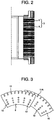
- the rotor core 5 is formed by axially stacking annular steel plates as shown in Fig. 4 , each annular steel plate being formed by circumferentially arranging segment cores 9, 10 adjacent to each other as shown in Fig. 5 , and the segment cores being fan-shaped steel plates and having a plurality of slots 11, 11A formed on outer periphery as shown in Fig. 3 .
- a plurality of bolt through holes 12 are formed in addition to the slots 11, 11A. After the annular steel plates are stacked up to a predetermined size, fastening bolts 14 are passed through the bolt through holes 12 to fasten with nuts (not shown) from opposite sides.
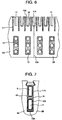
- slots 16 formed near opposite circumferential ends of the segment cores have a higher radial height and a larger circumferential width than the slots 11, 11A formed in circumferential intermediate portions of the segment cores 9, 10 as shown in Fig. 6 .
- a peripheral edge of the slot 11A in the segment core 10A adjacent to the segment cores 9A and 9B in the stacking direction faces into the slot 16.
- the rotor core 5 includes ventilating ducts extending from the inner diameter side to the outer diameter side for each predetermined stacking size to pass cooling air from the inner diameter side to the outer diameter side, and duct spacers 17 having a thickness equal to a width of the ventilating ducts are provided and duct spacers 18 are provided around the bolt through holes 12.
- protrusions extending in the stacking direction of the annular steel plates are formed on the duct spacers 17, and are engaged into engagement holes formed in the stacked rotor cores 5, thereby preventing the duct spacers 17 from being displaced radially outwardly by a centrifugal force during operation.
- fastening forces acting on the duct spacers 18 positioned on the inner diameter side are higher than those to the duct spacers 17 because of a need for firm fastening of the rotor cores 5 and a relationship with placement positions of the fastening bolts 14.
- the rotor core 5 is configured as described above, thereby preventing narrow areas from being produced in the rotor slots even if high speed rotation of the water turbine generator 1 during operation causes the circumferential ends of the segment cores 9, 10 to be displaced radially outwardly and circumferentially.
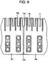
- opposite circumferential ends of the segment cores 9, 10 constituting the rotor core 5 receive a centrifugal force by rotation of the rotor 3 and are displaced radially outwardly and circumferentially even when the segment cores are fastened by the fastening bolt 14 and the nut as shown in Fig. 8 .
- a circumferential force cannot be transferred at joints (ends) 13A between adjacent segment cores 9A, 9B, but the circumferential force can be transferred by a friction force within contact surfaces of the duct spacers 17, 18, via adjacent segment cores 10 stacked in the stacking direction, thereby allowing a coupling state of the annular steel plate to be maintained during operation.
- This transfer of the circumferential force causes substantially uniform elastic deformation of the segment cores 9 in the circumferential direction, but the circumferential force does not act at the joints (ends) 13A, so that circumferential elastic deformation does not occur at the joints (ends) 13A. Therefore, at the joints (ends) 13A, a circumferential displacement is caused between the adjacent segment cores 9 and 10 in the stacking direction.
- portions near the opposite circumferential ends that are the joint (ends) 13A between the segment cores 9A and 9B are displaced radially outwardly in a state in which the annular steel plate is kept. Therefore, no gap is produced at the joint (ends) 13A during stop of the operation, while a gap is produced at the joint (ends) 13A during operation.
- a fastening force is applied to portions near the slot 16 formed at the joint (ends) 13A via the duct spacers 17, but the fastening force is smaller than the fastening force applied to the duct spacers 18 on the inner diameter side, and thus a friction force between the segment cores 9 and 10 stacked in the stacking direction is small, and the portions near the slot 16 are displaced radially outwardly and circumferentially to be tilted.
- the slot 16 formed near the joint (ends) 13A has a larger size than the slot 11A positioned in the circumferential intermediate portion of the adjacent segment core 10A in the stacking direction (axial direction), and thus even if the portion near the joint (end) 13A between the segment cores 9A and 9B is displaced radially outwardly and circumferentially, a peripheral edge of the slot 16 does not protrude into the slot 11A.
- an amount of displacement of the opposite circumferential ends of the segment cores 9, 10 during operation of the water turbine generator 1 is the largest at the ends of the segment cores 9 and 10 beyond the fastening bolts 14 positioned near the opposite circumferential ends of the segment cores 9, 10, and becomes smaller toward the circumferential intermediate portion of the segment cores 9, 10.
- the circumferential ends of the segment core 9 are significantly displaced and the amount of the displacement becomes smaller toward the intermediate portion of the segment core.
- the slots 16 at the circumferential ends of the segment cores 9 and 10 the largest, slots progressively smaller toward the circumferential intermediate portion, and a slot finally the same as the slots 11, 11A at a circumferential center, in other words, by forming the slots progressively larger from the circumferential center toward the circumferential ends of the segment core in accordance with the amount of the displacement, it is possible to prevent the edge of the slot 16 from protruding into the rotor slot extending axially over the entire length of the rotor core 5.
- the slot 16 is increased in width at opposite sides in a width direction as compared with the slots 11 and 11A, but the slot 16 may be increased in width at only a side with the edge of the slot 16 protruding into the rotor slots by the displacement. Further, noting only the width direction of the slot, half slots formed in the circumferential ends of the segment cores 9 and 10 do not need to be increased in width because the displacement does not cause the edge of the slot to protrude into the slot 11A formed in the adjacent segment core in the stacking direction.
- the water turbine generator 1 has been described above, but the present invention can be, of course, applied to any rotating electrical machine using fan-shaped segment cores in a rotor core.
Landscapes
- Engineering & Computer Science (AREA)
- Power Engineering (AREA)
- Manufacturing & Machinery (AREA)
- Iron Core Of Rotating Electric Machines (AREA)
Priority Applications (1)
| Application Number | Priority Date | Filing Date | Title |
|---|---|---|---|
| SI200931963T SI2136453T1 (sl) | 2008-06-18 | 2009-05-14 | Vrtljiv električni stroj |
Applications Claiming Priority (1)
| Application Number | Priority Date | Filing Date | Title |
|---|---|---|---|
| JP2008158574A JP5055206B2 (ja) | 2008-06-18 | 2008-06-18 | 回転電機 |
Publications (3)
| Publication Number | Publication Date |
|---|---|
| EP2136453A2 EP2136453A2 (en) | 2009-12-23 |
| EP2136453A3 EP2136453A3 (en) | 2018-01-10 |
| EP2136453B1 true EP2136453B1 (en) | 2019-02-20 |
Family
ID=41134559
Family Applications (1)
| Application Number | Title | Priority Date | Filing Date |
|---|---|---|---|
| EP09006537.6A Active EP2136453B1 (en) | 2008-06-18 | 2009-05-14 | Rotating electrical machine |
Country Status (8)
| Country | Link |
|---|---|
| US (1) | US8183735B2 (lt) |
| EP (1) | EP2136453B1 (lt) |
| JP (1) | JP5055206B2 (lt) |
| CN (1) | CN101610008B (lt) |
| ES (1) | ES2726034T3 (lt) |
| LT (1) | LT2136453T (lt) |
| SI (1) | SI2136453T1 (lt) |
| TR (1) | TR201906844T4 (lt) |
Families Citing this family (8)
| Publication number | Priority date | Publication date | Assignee | Title |
|---|---|---|---|---|
| US8626823B2 (en) * | 2007-11-13 | 2014-01-07 | Google Inc. | Page ranking system employing user sharing data |
| JP5480716B2 (ja) | 2010-05-13 | 2014-04-23 | 日立三菱水力株式会社 | 回転電機の回転子 |
| DE102012006169A1 (de) * | 2012-03-28 | 2013-10-02 | Sew-Eurodrive Gmbh & Co. Kg | Verfahren zum Herstellen eines Motors und Elektromotor mit einem Rotor |
| JP5897441B2 (ja) * | 2012-09-26 | 2016-03-30 | 株式会社日立製作所 | 回転電機 |
| EP2713478B1 (en) * | 2012-09-27 | 2019-11-13 | Siemens Gamesa Renewable Energy A/S | Outer structure of a generator |
| CN103051114B (zh) * | 2012-12-11 | 2014-11-05 | 信质电机股份有限公司 | 一种电机定子铁芯斜槽的加工方法 |
| CN105723592B (zh) * | 2013-11-08 | 2018-05-25 | 三菱电机株式会社 | 旋转电机的定子、以及旋转电机 |
| EP3703224B1 (en) * | 2019-03-01 | 2022-05-11 | Siemens Gamesa Renewable Energy A/S | Manufacturing method for a segmented stator or rotor of an electrical machine |
Family Cites Families (11)
| Publication number | Priority date | Publication date | Assignee | Title |
|---|---|---|---|---|
| DE1141020B (de) * | 1960-07-28 | 1962-12-13 | Licentia Gmbh | Walzenfoermiger Laeufer fuer Synchronmaschinen hoher Drehzahl |
| US3652889A (en) * | 1971-01-18 | 1972-03-28 | Gen Electric | Laminated dynamoelectric machine core and method of stacking |
| US3787744A (en) * | 1972-07-11 | 1974-01-22 | Hitachi Ltd | Laminated iron core of rotary electric machines |
| US4264836A (en) * | 1979-06-07 | 1981-04-28 | Dukshtau A A | Laminated rotor for a synchronous salient-pole electrical machine |
| JPS603648Y2 (ja) * | 1979-11-19 | 1985-02-01 | 三菱電機株式会社 | 電機子鉄心 |
| FR2524220A1 (fr) * | 1982-03-26 | 1983-09-30 | Alsthom Atlantique | Rotor a jante feuilletee segmentee et poles rapportes pour machine electrique |
| JPS59103582U (ja) * | 1982-12-27 | 1984-07-12 | 三菱電機株式会社 | 超電導回転電機の回転子 |
| JPS60152258A (ja) * | 1984-01-20 | 1985-08-10 | Toshiba Corp | 回転子鉄心の製造方法 |
| JPH0515093A (ja) | 1991-06-27 | 1993-01-22 | Tokyo Electric Power Co Inc:The | 回転電機の回転子鉄心 |
| JP3521261B2 (ja) * | 1998-04-13 | 2004-04-19 | 株式会社日立製作所 | 回転電機の回転子 |
| JP3993073B2 (ja) * | 2001-12-11 | 2007-10-17 | アスモ株式会社 | 回転電機の回転子及びその製造方法 |
-
2008
- 2008-06-18 JP JP2008158574A patent/JP5055206B2/ja active Active
-
2009
- 2009-05-06 US US12/436,478 patent/US8183735B2/en active Active
- 2009-05-14 EP EP09006537.6A patent/EP2136453B1/en active Active
- 2009-05-14 TR TR2019/06844T patent/TR201906844T4/tr unknown
- 2009-05-14 ES ES09006537T patent/ES2726034T3/es active Active
- 2009-05-14 SI SI200931963T patent/SI2136453T1/sl unknown
- 2009-05-14 LT LTEP09006537.6T patent/LT2136453T/lt unknown
- 2009-06-16 CN CN2009101424325A patent/CN101610008B/zh active Active
Non-Patent Citations (1)
| Title |
|---|
| None * |
Also Published As
| Publication number | Publication date |
|---|---|
| US8183735B2 (en) | 2012-05-22 |
| ES2726034T3 (es) | 2019-10-01 |
| EP2136453A2 (en) | 2009-12-23 |
| CN101610008B (zh) | 2012-07-04 |
| SI2136453T1 (sl) | 2019-06-28 |
| JP5055206B2 (ja) | 2012-10-24 |
| TR201906844T4 (tr) | 2019-05-21 |
| LT2136453T (lt) | 2019-03-25 |
| US20090315429A1 (en) | 2009-12-24 |
| EP2136453A3 (en) | 2018-01-10 |
| CN101610008A (zh) | 2009-12-23 |
| JP2010004583A (ja) | 2010-01-07 |
Similar Documents
| Publication | Publication Date | Title |
|---|---|---|
| EP2136453B1 (en) | Rotating electrical machine | |
| US8766505B2 (en) | Rotating electrical machine and method for manufacturing rotating electrical machine | |
| JP5324673B2 (ja) | 分割式コアを有する電動機の回転子及びその製造方法 | |
| JP5480716B2 (ja) | 回転電機の回転子 | |
| WO2017141361A1 (ja) | 回転電機及び回転電機の製造方法 | |
| WO2013008568A1 (ja) | 回転電機及び回転電機の固定子コイルの製造方法 | |
| US8866362B2 (en) | Lamination stack for an electrical machine stator | |
| US12255496B2 (en) | Joining a laminated core to a shaft | |
| CN114268197B (zh) | 一种轴向磁通电机的转子盘及成型方法 | |
| KR101976307B1 (ko) | 발전기용 스테이터 링 및 상기 스테이터 링을 포함하는 발전기 및 풍력 터빈 | |
| US20130099503A1 (en) | Lamination stack for an electrical machine stator | |
| US9106116B2 (en) | Rotor of rotating electrical machine | |
| US11316393B2 (en) | Magnetic sheet for rotor with a non-through shaft, method of obtaining such a sheet and associated rotor | |
| CN109560632B (zh) | 转子 | |
| US20130062991A1 (en) | Rotating electric machine | |
| CN110875659A (zh) | 旋转电机转子、电机及压缩机 | |
| EP4101053A1 (en) | Stator segment, stator, wind turbine and method of manufacturing a stator segment | |
| JP4848895B2 (ja) | 立軸回転電機の回転子 | |
| JPH0570149U (ja) | 超高速モータのロータ | |
| JPS63217941A (ja) | 回転電機の回転子 | |
| CN114598074B (zh) | 一种轴向磁场电机的转子齿及其制作方法 | |
| CN110365146B (zh) | 电动机转子、电动机及电动机转子的装配方法 | |
| JP4859357B2 (ja) | 回転電機の固定子鉄心の製造方法 | |
| WO2017149717A1 (ja) | 回転電機 | |
| US20240429762A1 (en) | Rotor body for a permanent magnet machine |
Legal Events
| Date | Code | Title | Description |
|---|---|---|---|
| PUAI | Public reference made under article 153(3) epc to a published international application that has entered the european phase |
Free format text: ORIGINAL CODE: 0009012 |
|
| 17P | Request for examination filed |
Effective date: 20090610 |
|
| AK | Designated contracting states |
Kind code of ref document: A2 Designated state(s): AT BE BG CH CY CZ DE DK EE ES FI FR GB GR HR HU IE IS IT LI LT LU LV MC MK MT NL NO PL PT RO SE SI SK TR |
|
| RAP1 | Party data changed (applicant data changed or rights of an application transferred) |
Owner name: HITACHI MITSUBISHI HYDRO CORPORATION |
|
| PUAL | Search report despatched |
Free format text: ORIGINAL CODE: 0009013 |
|
| AK | Designated contracting states |
Kind code of ref document: A3 Designated state(s): AT BE BG CH CY CZ DE DK EE ES FI FR GB GR HR HU IE IS IT LI LT LU LV MC MK MT NL NO PL PT RO SE SI SK TR |
|
| AX | Request for extension of the european patent |
Extension state: AL BA RS |
|
| RIC1 | Information provided on ipc code assigned before grant |
Ipc: H02K 15/02 20060101ALI20171204BHEP Ipc: H02K 1/26 20060101AFI20171204BHEP |
|
| STAA | Information on the status of an ep patent application or granted ep patent |
Free format text: STATUS: REQUEST FOR EXAMINATION WAS MADE |
|
| GRAP | Despatch of communication of intention to grant a patent |
Free format text: ORIGINAL CODE: EPIDOSNIGR1 |
|
| STAA | Information on the status of an ep patent application or granted ep patent |
Free format text: STATUS: GRANT OF PATENT IS INTENDED |
|
| INTG | Intention to grant announced |
Effective date: 20181022 |
|
| GRAS | Grant fee paid |
Free format text: ORIGINAL CODE: EPIDOSNIGR3 |
|
| GRAA | (expected) grant |
Free format text: ORIGINAL CODE: 0009210 |
|
| STAA | Information on the status of an ep patent application or granted ep patent |
Free format text: STATUS: THE PATENT HAS BEEN GRANTED |
|
| AK | Designated contracting states |
Kind code of ref document: B1 Designated state(s): AT BE BG CH CY CZ DE DK EE ES FI FR GB GR HR HU IE IS IT LI LT LU LV MC MK MT NL NO PL PT RO SE SI SK TR |
|
| REG | Reference to a national code |
Ref country code: GB Ref legal event code: FG4D |
|
| REG | Reference to a national code |
Ref country code: CH Ref legal event code: EP |
|
| REG | Reference to a national code |
Ref country code: DE Ref legal event code: R096 Ref document number: 602009057019 Country of ref document: DE |
|
| REG | Reference to a national code |
Ref country code: AT Ref legal event code: REF Ref document number: 1099457 Country of ref document: AT Kind code of ref document: T Effective date: 20190315 |
|
| REG | Reference to a national code |
Ref country code: IE Ref legal event code: FG4D |
|
| REG | Reference to a national code |
Ref country code: NL Ref legal event code: MP Effective date: 20190220 |
|
| PG25 | Lapsed in a contracting state [announced via postgrant information from national office to epo] |
Ref country code: SE Free format text: LAPSE BECAUSE OF FAILURE TO SUBMIT A TRANSLATION OF THE DESCRIPTION OR TO PAY THE FEE WITHIN THE PRESCRIBED TIME-LIMIT Effective date: 20190220 Ref country code: NO Free format text: LAPSE BECAUSE OF FAILURE TO SUBMIT A TRANSLATION OF THE DESCRIPTION OR TO PAY THE FEE WITHIN THE PRESCRIBED TIME-LIMIT Effective date: 20190520 Ref country code: PT Free format text: LAPSE BECAUSE OF FAILURE TO SUBMIT A TRANSLATION OF THE DESCRIPTION OR TO PAY THE FEE WITHIN THE PRESCRIBED TIME-LIMIT Effective date: 20190620 Ref country code: FI Free format text: LAPSE BECAUSE OF FAILURE TO SUBMIT A TRANSLATION OF THE DESCRIPTION OR TO PAY THE FEE WITHIN THE PRESCRIBED TIME-LIMIT Effective date: 20190220 |
|
| PG25 | Lapsed in a contracting state [announced via postgrant information from national office to epo] |
Ref country code: BG Free format text: LAPSE BECAUSE OF FAILURE TO SUBMIT A TRANSLATION OF THE DESCRIPTION OR TO PAY THE FEE WITHIN THE PRESCRIBED TIME-LIMIT Effective date: 20190520 Ref country code: NL Free format text: LAPSE BECAUSE OF FAILURE TO SUBMIT A TRANSLATION OF THE DESCRIPTION OR TO PAY THE FEE WITHIN THE PRESCRIBED TIME-LIMIT Effective date: 20190220 Ref country code: LV Free format text: LAPSE BECAUSE OF FAILURE TO SUBMIT A TRANSLATION OF THE DESCRIPTION OR TO PAY THE FEE WITHIN THE PRESCRIBED TIME-LIMIT Effective date: 20190220 Ref country code: IS Free format text: LAPSE BECAUSE OF FAILURE TO SUBMIT A TRANSLATION OF THE DESCRIPTION OR TO PAY THE FEE WITHIN THE PRESCRIBED TIME-LIMIT Effective date: 20190620 Ref country code: GR Free format text: LAPSE BECAUSE OF FAILURE TO SUBMIT A TRANSLATION OF THE DESCRIPTION OR TO PAY THE FEE WITHIN THE PRESCRIBED TIME-LIMIT Effective date: 20190521 Ref country code: HR Free format text: LAPSE BECAUSE OF FAILURE TO SUBMIT A TRANSLATION OF THE DESCRIPTION OR TO PAY THE FEE WITHIN THE PRESCRIBED TIME-LIMIT Effective date: 20190220 |
|
| REG | Reference to a national code |
Ref country code: AT Ref legal event code: MK05 Ref document number: 1099457 Country of ref document: AT Kind code of ref document: T Effective date: 20190220 |
|
| REG | Reference to a national code |
Ref country code: ES Ref legal event code: FG2A Ref document number: 2726034 Country of ref document: ES Kind code of ref document: T3 Effective date: 20191001 |
|
| PG25 | Lapsed in a contracting state [announced via postgrant information from national office to epo] |
Ref country code: DK Free format text: LAPSE BECAUSE OF FAILURE TO SUBMIT A TRANSLATION OF THE DESCRIPTION OR TO PAY THE FEE WITHIN THE PRESCRIBED TIME-LIMIT Effective date: 20190220 Ref country code: SK Free format text: LAPSE BECAUSE OF FAILURE TO SUBMIT A TRANSLATION OF THE DESCRIPTION OR TO PAY THE FEE WITHIN THE PRESCRIBED TIME-LIMIT Effective date: 20190220 Ref country code: EE Free format text: LAPSE BECAUSE OF FAILURE TO SUBMIT A TRANSLATION OF THE DESCRIPTION OR TO PAY THE FEE WITHIN THE PRESCRIBED TIME-LIMIT Effective date: 20190220 Ref country code: IT Free format text: LAPSE BECAUSE OF FAILURE TO SUBMIT A TRANSLATION OF THE DESCRIPTION OR TO PAY THE FEE WITHIN THE PRESCRIBED TIME-LIMIT Effective date: 20190220 Ref country code: CZ Free format text: LAPSE BECAUSE OF FAILURE TO SUBMIT A TRANSLATION OF THE DESCRIPTION OR TO PAY THE FEE WITHIN THE PRESCRIBED TIME-LIMIT Effective date: 20190220 Ref country code: RO Free format text: LAPSE BECAUSE OF FAILURE TO SUBMIT A TRANSLATION OF THE DESCRIPTION OR TO PAY THE FEE WITHIN THE PRESCRIBED TIME-LIMIT Effective date: 20190220 |
|
| REG | Reference to a national code |
Ref country code: DE Ref legal event code: R097 Ref document number: 602009057019 Country of ref document: DE |
|
| PG25 | Lapsed in a contracting state [announced via postgrant information from national office to epo] |
Ref country code: PL Free format text: LAPSE BECAUSE OF FAILURE TO SUBMIT A TRANSLATION OF THE DESCRIPTION OR TO PAY THE FEE WITHIN THE PRESCRIBED TIME-LIMIT Effective date: 20190220 |
|
| REG | Reference to a national code |
Ref country code: DE Ref legal event code: R119 Ref document number: 602009057019 Country of ref document: DE |
|
| PLBE | No opposition filed within time limit |
Free format text: ORIGINAL CODE: 0009261 |
|
| STAA | Information on the status of an ep patent application or granted ep patent |
Free format text: STATUS: NO OPPOSITION FILED WITHIN TIME LIMIT |
|
| REG | Reference to a national code |
Ref country code: CH Ref legal event code: PL |
|
| PG25 | Lapsed in a contracting state [announced via postgrant information from national office to epo] |
Ref country code: AT Free format text: LAPSE BECAUSE OF FAILURE TO SUBMIT A TRANSLATION OF THE DESCRIPTION OR TO PAY THE FEE WITHIN THE PRESCRIBED TIME-LIMIT Effective date: 20190220 |
|
| 26N | No opposition filed |
Effective date: 20191121 |
|
| PG25 | Lapsed in a contracting state [announced via postgrant information from national office to epo] |
Ref country code: LI Free format text: LAPSE BECAUSE OF NON-PAYMENT OF DUE FEES Effective date: 20190531 Ref country code: MC Free format text: LAPSE BECAUSE OF FAILURE TO SUBMIT A TRANSLATION OF THE DESCRIPTION OR TO PAY THE FEE WITHIN THE PRESCRIBED TIME-LIMIT Effective date: 20190220 Ref country code: CH Free format text: LAPSE BECAUSE OF NON-PAYMENT OF DUE FEES Effective date: 20190531 |
|
| REG | Reference to a national code |
Ref country code: BE Ref legal event code: MM Effective date: 20190531 |
|
| PG25 | Lapsed in a contracting state [announced via postgrant information from national office to epo] |
Ref country code: LU Free format text: LAPSE BECAUSE OF NON-PAYMENT OF DUE FEES Effective date: 20190514 |
|
| PG25 | Lapsed in a contracting state [announced via postgrant information from national office to epo] |
Ref country code: IE Free format text: LAPSE BECAUSE OF NON-PAYMENT OF DUE FEES Effective date: 20190514 Ref country code: DE Free format text: LAPSE BECAUSE OF NON-PAYMENT OF DUE FEES Effective date: 20191203 |
|
| PG25 | Lapsed in a contracting state [announced via postgrant information from national office to epo] |
Ref country code: BE Free format text: LAPSE BECAUSE OF NON-PAYMENT OF DUE FEES Effective date: 20190531 |
|
| PG25 | Lapsed in a contracting state [announced via postgrant information from national office to epo] |
Ref country code: FR Free format text: LAPSE BECAUSE OF NON-PAYMENT OF DUE FEES Effective date: 20190531 |
|
| PG25 | Lapsed in a contracting state [announced via postgrant information from national office to epo] |
Ref country code: CY Free format text: LAPSE BECAUSE OF FAILURE TO SUBMIT A TRANSLATION OF THE DESCRIPTION OR TO PAY THE FEE WITHIN THE PRESCRIBED TIME-LIMIT Effective date: 20190220 |
|
| PG25 | Lapsed in a contracting state [announced via postgrant information from national office to epo] |
Ref country code: MT Free format text: LAPSE BECAUSE OF FAILURE TO SUBMIT A TRANSLATION OF THE DESCRIPTION OR TO PAY THE FEE WITHIN THE PRESCRIBED TIME-LIMIT Effective date: 20190220 Ref country code: HU Free format text: LAPSE BECAUSE OF FAILURE TO SUBMIT A TRANSLATION OF THE DESCRIPTION OR TO PAY THE FEE WITHIN THE PRESCRIBED TIME-LIMIT; INVALID AB INITIO Effective date: 20090514 |
|
| PG25 | Lapsed in a contracting state [announced via postgrant information from national office to epo] |
Ref country code: MK Free format text: LAPSE BECAUSE OF FAILURE TO SUBMIT A TRANSLATION OF THE DESCRIPTION OR TO PAY THE FEE WITHIN THE PRESCRIBED TIME-LIMIT Effective date: 20190220 |
|
| PGFP | Annual fee paid to national office [announced via postgrant information from national office to epo] |
Ref country code: ES Payment date: 20250627 Year of fee payment: 17 Ref country code: GB Payment date: 20250521 Year of fee payment: 17 |
|
| PGFP | Annual fee paid to national office [announced via postgrant information from national office to epo] |
Ref country code: LT Payment date: 20250424 Year of fee payment: 17 |
|
| PGFP | Annual fee paid to national office [announced via postgrant information from national office to epo] |
Ref country code: TR Payment date: 20250506 Year of fee payment: 17 |
|
| PGFP | Annual fee paid to national office [announced via postgrant information from national office to epo] |
Ref country code: SI Payment date: 20250504 Year of fee payment: 17 |