EP2136334B1 - Système, appareil, procédé et produit de programme informatique pour reconnaissance de position optique - Google Patents
Système, appareil, procédé et produit de programme informatique pour reconnaissance de position optique Download PDFInfo
- Publication number
- EP2136334B1 EP2136334B1 EP09162261.3A EP09162261A EP2136334B1 EP 2136334 B1 EP2136334 B1 EP 2136334B1 EP 09162261 A EP09162261 A EP 09162261A EP 2136334 B1 EP2136334 B1 EP 2136334B1
- Authority
- EP
- European Patent Office
- Prior art keywords
- frame
- object holder
- coordinates
- optical
- orientation
- Prior art date
- Legal status (The legal status is an assumption and is not a legal conclusion. Google has not performed a legal analysis and makes no representation as to the accuracy of the status listed.)
- Active
Links
Images


Classifications
-
- G—PHYSICS
- G01—MEASURING; TESTING
- G01B—MEASURING LENGTH, THICKNESS OR SIMILAR LINEAR DIMENSIONS; MEASURING ANGLES; MEASURING AREAS; MEASURING IRREGULARITIES OF SURFACES OR CONTOURS
- G01B11/00—Measuring arrangements characterised by the use of optical techniques
- G01B11/24—Measuring arrangements characterised by the use of optical techniques for measuring contours or curvatures
-
- G—PHYSICS
- G06—COMPUTING OR CALCULATING; COUNTING
- G06T—IMAGE DATA PROCESSING OR GENERATION, IN GENERAL
- G06T7/00—Image analysis
- G06T7/30—Determination of transform parameters for the alignment of images, i.e. image registration
- G06T7/33—Determination of transform parameters for the alignment of images, i.e. image registration using feature-based methods
-
- G—PHYSICS
- G06—COMPUTING OR CALCULATING; COUNTING
- G06T—IMAGE DATA PROCESSING OR GENERATION, IN GENERAL
- G06T2207/00—Indexing scheme for image analysis or image enhancement
- G06T2207/10—Image acquisition modality
- G06T2207/10028—Range image; Depth image; 3D point clouds
-
- G—PHYSICS
- G06—COMPUTING OR CALCULATING; COUNTING
- G06T—IMAGE DATA PROCESSING OR GENERATION, IN GENERAL
- G06T2207/00—Indexing scheme for image analysis or image enhancement
- G06T2207/30—Subject of image; Context of image processing
- G06T2207/30004—Biomedical image processing
- G06T2207/30036—Dental; Teeth
-
- G—PHYSICS
- G06—COMPUTING OR CALCULATING; COUNTING
- G06T—IMAGE DATA PROCESSING OR GENERATION, IN GENERAL
- G06T2207/00—Indexing scheme for image analysis or image enhancement
- G06T2207/30—Subject of image; Context of image processing
- G06T2207/30204—Marker
Definitions
- the present invention generally relates to optical position recognition, and more particularly to methods, systems, apparatuses, and computer program products for employing optical position recognition techniques to correlate frame data acquired during multiple measurements (i.e., captured representations, such as, e.g., images or scans) of an object for use in obtaining a three-dimensional representation of the object.
- captured representations such as, e.g., images or scans
- the measuring field or the measuring volume of the optical measurement system is smaller than a volume of the object to be measured. Accordingly, it is necessary to perform multiple measurements of different portions of the object to acquire substantially complete representations for the object.
- the object is moved relative to the optical measurement system between measurements.
- the data acquired from each measurement must be correlated, i.e., mapped onto a common coordinate system, to obtain a composite three-dimensional representation of the entire object.
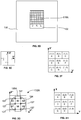
- FIG. 10A depicts an exemplary system 1000 that uses conventional mechanical registration techniques to correlate three-dimensional data acquired during multiple measurements.
- An example of such a system is disclosed in H. Kato ET AL: "Marker tracking and HMD calibration for a video-based augmented reality conferencing system", Augmented Reality, 1999 .
- the system 1000 includes measuring optics 1002 and a slide 1004.
- a support member 1006 positions the measuring optics 1002 at a fixed orientation relative to the slide 1004, such that there is no relative movement between the measuring optics 1002 and the slide 1004.
- a mechanical grid 1008 is provided on an upper surface of the slide 1004.
- An object 1010 is secured to an object holder 1012.
- the object holder 1012 is positioned in predetermined locations on the mechanical grid 1008. A measurement is performed and a frame of three-dimensional data is acquired at each location. A composite three-dimensional representation of the entire object is created by combining the frame data according to well-known frame registration techniques.
- a disadvantage of the system 1000 is that the object holder 1012 can be placed only in predetermined locations that are accommodated by the mechanical grid 1008, which may not be optimal locations for acquiring three-dimensional data.
- Conventional three-dimensional measurement systems also may employ optical registration techniques to correlate frame data from multiple measurements. Positions are determined by points of reference located on an object holder.
- a Cercon Eye Scanner from DeguDent GmbH employs optical registration techniques, for example.
- FIG. 10B depicts an exemplary system 1050 that uses conventional optical registration techniques to correlate three-dimensional data acquired during multiple measurements.
- the system 1050 includes measuring optics 1052 and a slide 1054.
- a support member 1056 positions the measuring optics 1052 at a fixed orientation relative to the slide 1054, such that there is no relative movement between the measuring optics 1052 and the slide 1054.
- An object 1058 is secured to an object holder 1060.
- the object holder 1060 includes a reference position marker adjuster 1061 that positions a reference position marker 1062 above the object 1058.
- the object holder 1060 is then moved over the slide 1054 in discrete steps.
- a measurement is performed and a frame of three-dimensional data is acquired during each step. Each measurement must include the reference position markers 1062.
- Optical registration techniques are used to identify the reference position marker 1062 and generate corresponding positioning information for each frame of three-dimensional data.
- a composite three-dimensional representation of the entire object is created by combining the frame data according to well-known frame
- the measuring optics 1052 typically include a camera (not illustrated) that is employed to observe the reference position marker 1062 on the object holder 1060.
- a disadvantage of the system 1050 is that the camera must be able to view the reference position marker 1062 during each measurement.
- the reference position marker 1062 must not be covered by the object 1058 or otherwise obscured from the camera while measurements are taken.
- the present invention overcomes the above limitations associated with measuring a three-dimensional object using conventional frame registration techniques.
- the present invention meets the above-identified needs by providing method and system.
- Various embodiments of the present invention advantageously enable measurement data acquired during multiple measurements of an object to be correlated and combined to form composite measurement data of the object.
- a method of evaluating an object disposed on an upper surface of an object holder At least one first frame representing a captured portion of the object is acquired, while the object holder is positioned at each of a plurality of locations. At least one second frame representing a captured portion of at least one other surface of the object holder is acquired, while the object holder is positioned at each of the plurality of locations, where the at least one other surface of the object holder is disposed in space lower than the upper surface of the object holder. At least one spatial characteristic associated with the captured portion of the object is determined based on at least one of the acquired frames.
- the method also may include creating composite data based on the acquired frames.
- the composite data may form a three-dimensional representation of the object.
- the method may include, for each second frame, determining an orientation and coordinates associated with the captured portion of the at least one other surface of the object holder, and for each first frame, translating coordinates associated with the captured portion of the object, based on the orientation and the coordinates determined for a corresponding second frame.
- the at least one other surface may be a lower surface of the object holder.
- the at least one other surface may include at least one optical marker
- the method may further include determining an orientation of at least one optical marker captured in each second frame, determining a value of the at least one optical marker captured in each second frame, and determining coordinates of a reference point associated with each second frame.
- each first frame may include measurement data and each second frame may include image data.
- Example embodiments of the present invention relate to methods, systems, apparatuses, and computer program products for employing optical position recognition techniques to correlate measurement data acquired during multiple measurements of surfaces of an object, to be used to obtain a composite representation of the object, even though a field of view of a measuring unit may be smaller than the size of the object.
- Each is useful for obtaining composite representations of any type of object, although the present application is described in the context of a dental apparatus that obtains composite three-dimensional representations of actual or prosthetic teeth or dental molds or castings.
- FIG. 1A illustrates a system 100 according to an exemplary embodiment of the present invention.
- the system 100 enables images to be captured that can be used to form a three-dimensional representation of an object 102, such as a tooth or other object.
- the system 100 includes a measuring unit 104 and a slide 106.
- a support member 108 positions the measuring unit 104 at a fixed orientation relative to the slide 106, such that there is no relative movement between the measuring unit 104 and the slide 106.
- the measuring unit 104 may be comprised of any suitable conventional or later developed three-dimensional measuring unit.
- the measuring unit 104 may include a fringe-projection system, which consists of a fringe pattern projector and a camera.
- the measuring unit 104 that can be used with the present invention is not limited to a fringe-projection unit.
- Other types of three-dimensional measuring units may be used, e.g., the measuring unit 104 may employ confocal laser scanning microscopy, optical coherence tomography, white light interferometry, or other techniques known in the art.
- the object 102 to be measured is placed on or secured to an object holder 110, which has an optical coding pattern 112 securely attached at a lower portion thereof.
- the optical coding pattern 112 could be integrally formed with the lower portion of the object holder 110 without departing from the scope of the present invention.
- a camera unit 114 is disposed within the slide 106, or, in other embodiments, beneath the slide 106 so long as the optical coding pattern 112 is within the field of view of the camera unit 114.
- a transparent portion 116 is provided on an upper surface of the slide 106.
- the transparent portion 116 enables the camera unit 114 to view at least a portion of the optical coding pattern 112 to acquire image data representing that portion, which data is processed to determine spatial characteristics of the optical coding pattern 112, such as an orientation and a relative position of the optical coding pattern 112 with respect to the camera unit 114. Spatial characteristics of the optical coding pattern 112 are used to determine corresponding spatial characteristics of the object holder 110, such as an orientation and a relative position of the object holder 110 with respect to the measuring unit 104, as described below.
- FIG. 1B illustrates the object 102 and the object holder 110 depicted in FIG. 1A , as viewed from a perspective looking down on those components.
- the object 102 includes an upper-right portion A, a lower-right portion B, a lower-left portion C, and an upper-left portion D.
- the measuring unit 104 acquires measurement data in a measuring field 118 of the measuring unit 104.
- the terms "measuring field,” “field of view,” “measuring area,” and “measuring volume” may be used interchangeably herein. Since the measuring field 118 can be smaller than the object 102, multiple measurements can be performed to acquire measurement data for the object 102, for use in obtaining a three-dimensional representation thereof, according to an aspect of the invention.
- FIG. 1C illustrates an exemplary optical coding pattern 112 of the present invention.
- the optical coding pattern 112 includes a plurality of horizontal line segments 120 and a plurality of vertical line segments 122, which form a grid pattern.
- the optical coding pattern 112 also includes a plurality of optical markers 124 that are used to identify predetermined locations on the optical coding pattern 112, such as the intersections of the horizontal line segments 120 and vertical line segments 122.
- the optical markers 124 of the exemplary optical coding pattern 112 are numbers that range from 1-225, however, other types of optical markers 124 can be used.
- the optical markers 124 may include a plurality of unique bar codes, and/or a plurality of circles each having a different radius. Other codes or symbols that uniquely identify a plurality of locations on the optical coding pattern 112 also may be used.
- FIG. 1D illustrates a portion 100' of the system 100 illustrated in FIG. 1A , such as measuring unit 104, object holder 110, optical coding pattern 112, camera unit 114, and measuring field 118.
- the measuring unit 104 acquires measurement data of an object 102 in the measuring field 118 (within the field of view) of the measuring unit 104.
- the camera unit 114 acquires image data corresponding to an optical coding pattern 112, which is formed on a lower surface of the object holder 110.
- the camera unit 114 can be any camera that is capable of taking a two-dimensional image of the optical coding pattern 112.
- the camera unit 114 acquires image data corresponding to a view area 126.
- the object holder 110 in the present example is deemed to be positioned such that a center of the measuring field 118 is aligned with a center of the object holder 110, which is aligned with a center of the view area 126 of the camera unit 114.
- the center of the object holder 110 is indicated by reference number 110A.
- a pixel 123 corresponding to the center of the view area 126 of the camera unit 114 is aligned with the center of the "113" optical marker of the optical coding pattern 112', as shown in FIG. 1E .
- the "113" optical markers 124 corresponds to a center optical marker 124 of the optical coding pattern 112, as shown in FIG. 1C .
- the center of the measuring field 118 is aligned with the center pixel 123 of the view area 126 of the camera unit 114.
- the center of the measuring field 118 may be offset from the center of the view area 126 of the camera unit 114 by a fixed amount, which is taken into account when translating coordinates (to be described below) representing a portion of the optical coding pattern 112 in a center of the view area 126 of the camera unit 114 to corresponding coordinates of a center of the measuring field 118 in a reference coordinate system of the object holder 110.
- FIG. 1D Also shown in FIG. 1D are arrows or axes labeled 125A, 125B, and 125C indicating reference orientations for coordinate systems of the measuring unit 104, the optical coding pattern 112, and the camera unit 114, respectively.
- FIG. 2 illustrates an exemplary process, according to an aspect of the invention, for obtaining images of, and spatial characteristics (e.g., spatial coordinates and orientations) associated with, an object (e.g., one or more teeth), for use in obtaining a three-dimensional representation thereof.
- the process can be performed by an optical position recognition system, such as the systems illustrated in FIGS. 1A and 8 , for example.
- an optical position recognition system such as the systems illustrated in FIGS. 1A and 8 , for example.
- the process begins in Step S200. Initially, the object 102 is placed on or secured to an upper surface of the object holder 110.
- Step S202 the object holder 110 is positioned at a selected location on the slide 106.
- Step S204 the measuring unit 104 acquires measurement data in the measuring field 118 in which a portion of the object 102 appears (i.e., the measuring unit 104 captures an image frame of that portion).
- Step S206 the camera unit 114 acquires image data of at least a portion of the optical coding pattern 112 in the field of view (view area) 126 of the camera unit 114 (i.e., the camera unit 114 obtains or captures a digitized scan or image frame of that portion of the optical coding pattern 112). That is, the camera unit 114 acquires image data corresponding to a portion of the optical coding pattern 112 that is disposed over and faces the transparent portion 116 of the slide 106.
- Step S204 and Step S206 occur simultaneously for each position of the object holder; although in other embodiments they need not be, in which case the steps are correlated for each such position.
- Step S208 the processor of the system 100 uses a software module to process the image data obtained in Step S206 to determine values of one or more of the captured optical markers 124, which values are used in a manner to be described below (e.g ., Step S212) to identify one or more intersections of line segments surrounding or adjacent to at least one of the captured optical markers 124.
- a software module may be used to determine values of a captured optical marker 124.
- a processor e.g., processor 906 of FIG. 9 to be described below uses a software module to process the image data obtained in Step S206 to determine a value representing a spatial characteristic (i.e., an orientation) of the optical coding pattern 112 with respect to a reference orientation (e.g., 125B).
- the software module is used to determine an orientation of one or more of the optical markers 124 to determine the orientation of the optical coding pattern 112.
- the software module may use the values of at least two captured optical markers 124 to determine the orientation of the optical coding pattern 112. This is because in some cases it can be more accurate to determine an orientation based on more than a single symmetrical marker, such as circle. In an example embodiment, the software module may make the determination based on an orientation of one or more line segments that intersect the centers of two identified circular optical markers 124.
- Step S210 the software module is used to determine an orientation of one or more of the optical markers 124 and an orientation of one or more of the horizontal line segments 120 and/or the vertical line segments 122 to determine an orientation of the optical coding pattern 112 with respect to a reference orientation.
- the manner in which orientations are determined for one or more line segments, such as, e.g., segments 120 and/or 122, one or more optical markers 124, and the optical coding pattern 112 can be according to any suitable technique used to determine orientations of objects.
- Location information representing coordinates of predetermined locations of each intersection of the horizontal line segments 120 and the vertical line segments 122 of the optical coding pattern 112 is stored in a memory unit (e.g., secondary memory 910 of FIG. 9 to be described below) of the system 100.
- the location information may be derived from calibration measurements or may be deduced from a specification for the optical coding pattern 112.
- the location information is stored in the memory unit prior to acquiring measurement data (e.g., Step S204) and is used to correlate measurement data acquired during multiple scans of an object.
- Step S212 the processor of the system 100 uses a software module to determine spatial characteristics such as coordinates that correspond to a center of the portion of the optical coding pattern 112 captured in the view area 126 of the camera unit 114.
- the software module makes this determination based on at least one of (a) particular intersections of the optical coding pattern 112 that are observed in the view area 126 of the camera unit 114, (b) location information associated with the observed intersections, (c) the values of the optical markers 124 determined in Step S208, and (d) the orientation of the optical coding pattern 112 determined in Step S210.
- Step S212 can be performed by identifying one of the intersections surrounding or adjacent to an observed optical marker 124, retrieving coordinates (of the location information) corresponding to the identified intersection, and, based on these coordinates and the orientation of the optical coding pattern 112 obtained in Step S210, performing linear interpolation in a known manner to determine coordinates corresponding to a center of the portion of the optical coding pattern 112 captured in the view area 126 of the camera unit 114.
- Step S214 the processor of the system 100 uses a software module to translate coordinates associated with the center of the portion of the optical coding pattern 112 captured in the view area 126 of the camera unit 114 (as determined in Step S212) to corresponding coordinates of a center of the measuring field 118, in the coordinate system of the upper surface of the object holder 110.
- FIG. 6A shows a coordinate of (20,-20) in a coordinate system 130 of the optical coding pattern 112
- 7A shows a coordinate of (20,20) converted into a reference coordinate system 140 of the upper surface of the object holder 110.
- the correspondence between coordinates in the coordinate system 130 of the optical coding pattern 112 and the reference coordinate system 140 of the upper surface of the object holder 110 depends on a predefined relationship between the two systems.
- Step S214 can take into account that relationship as well.
- Step S216 the processor of the system 100 uses a software module to perform a translation of information obtained in Step S210 and a translation of spatial characteristics, such as coordinates associated with each datum of the measurement data acquired in Step S204, in a manner to be described below. Those coordinates may have been determined prior to Step S216, such as in Step S204, for example, or may be determined at the outset of Step S216. Those coordinates are in a coordinate system of the measuring unit 104.
- Step S216 in that step the software module translates the orientation of the optical coding pattern 112 in the coordinate system of the optical coding pattern 112, determined in Step S210, to a corresponding orientation of the object holder 110 in the reference coordinate of the upper surface of the object holder 110.
- the orientation in the coordinate system of the optical coding pattern 112 is "mapped" to a corresponding orientation in the reference coordinate system of the upper surface of the object holder 110.
- the software module then translates, using a mathematical transformation, coordinates associated with each datum of the measurement data acquired in Step S204 from the coordinate system of the measuring unit 104 to the reference coordinate system of the upper surface of the object holder 110. In this manner, despite where the object holder 110 is orientated when measurement data is taken, the acquired data may be placed in a reference orientation.
- Steps S214 and S216 can be performed using any suitable translation algorithms operable according to this description, as would be readily appreciated by one skilled in the art in view of this description.
- Step S2108 a determination is made whether more measurements are to be performed (e.g., whether additional measurements need to be performed to capture other desired parts of the object 102). If more measurements are to be performed ("Yes" at Step S218), Step S202 is repeated so that the object holder 110 is moved to another selected location on the slide 106, and Steps S204 through S218 are repeated for that location as described above. If no more measurements are to be performed ("No" at Step S218), the process ends in Step S220. All frames of measurement data have translated coordinates that are correlated in the reference coordinate system.
- Step S220 can include combining the measurement data obtained in Step S204 based on the translated coordinates obtained in Step S216, to provide a composite three-dimensional representation of the captured parts of the object 102.
- This formation of the composite representation may be performed according to any suitable frame registration techniques, such as, e.g., an Iterative Closest Point (ICP) algorithm.
- ICP Iterative Closest Point
- no frame registration is needed, as the information from the camera unit 114 is sufficient to create a composite three-dimensional representation of the captured parts of the object 102.
- FIGS. 3A-3J illustrate a first example of how the system 100 of FIG. 1A correlates acquired measurement data (e.g., Steps S206 through S216 of FIG. 2 ) for the object 102 according to an exemplary embodiment of the present invention.
- the object 102 is secured to the object holder 110, for example, with an adhesive.
- the object 102 includes portions identified for illustrative purposes as portions A through L.
- An exemplary object holder 110 has a square-shaped cross-sectional area, with each side of the square having a length of 10 centimeters (cm).
- a reference coordinate system (X, Y) of the upper surface of the object holder 110 has an origin corresponding to a center of the square, as shown in FIG. 3B .
- the coordinates of the reference coordinate system (X,Y) are spaced in 1 cm increments. Accordingly, each quadrant of the reference coordinate system (X,Y) is a 5 cm by 5 cm square, and coordinates within each quadrant range in magnitude between zero and 5 cm, as shown in FIG. 3B.
- FIG. 3C depicts a representation of portions A through L of the object 102 and associated coordinates in the reference coordinate system (X,Y).
- FIG. 3D the object holder 110 is positioned so that the measuring unit 104 (not shown in FIG. 3D ) acquires measurement data (e.g., Step S204 in FIG. 2 ) in a measuring field 118A that includes an upper portion of the object 102.
- FIG. 3E illustrates a coordinate system (X', Y') of the measuring unit 104 (not shown in FIG. 3E ). The origin of the coordinate system (X', Y') of the measuring unit 104 corresponds to the center of the measuring field 118A.
- FIG. 3F depicts a representation of measurement data corresponding to portions A through I of the object 102, and associated coordinates in the coordinate system (X', Y') of the measuring unit 104.
- FIG. 3G illustrates a portion 112A of the optical coding pattern 112 and a corresponding view area 126A of the camera unit 114 (not shown in FIG. 3G ), when the object holder 110 is positioned as shown in FIG. 3D .
- the camera view area 126A is centered between the "83" and "98" optical markers 124 in a coordinate system (X'', Y'') of the optical coding pattern 112, when the object holder 110 is positioned as shown in FIG. 3D .
- This relationship can be appreciated further in view of FIGS. 1A , 1C , and 1D .
- the optical coding pattern 112 is oriented such that the upper-most row (including the values "1" to “15” among the optical marker 124 shown in FIG. 1C ) is positioned away from the support member 108 and so that the lower-most row (including the values "211" to "225” among the optical markers 124 shown in FIG. 1C ) is positioned closest to the support member 108.
- the camera unit 114 can envision, in the view area 126A, six intersections 127 of line segments and six optical markers 124 ( e.g ., Step S206 in FIG. 2 ).
- the processor uses a software module to determine at least one value of at least one of the optical markers 124 ( e.g . Step S208 of FIG. 2 ).
- the processor also uses a software module to determine an orientation of at least one of the optical markers 124, which is used to determine an orientation of the optical coding pattern 112 ( e.g . Step S210 of FIG. 2 ).
- the processor uses a software module to retrieve coordinates associated with at least one of the intersections 127 of line segments from a memory unit (e.g ., secondary memory 910 of FIG. 9 to be described below), which the processor uses to determine coordinates, in the coordinate system (X'', Y'') of the optical coding pattern 112, of a location of a portion 112A of the optical coding pattern 112 that corresponds to the center of the view area 126A ( e.g . Step S212 of FIG. 2 ).
- a software module uses a software module to retrieve coordinates associated with at least one of the intersections 127 of line segments from a memory unit (e.g ., secondary memory 910 of FIG. 9 to be described below), which the processor uses to determine coordinates, in the coordinate system (X'', Y'') of the optical coding pattern 112, of a location of a portion 112A of the optical coding pattern 112 that corresponds to the center of the view area 126A ( e.g . Step
- the processor employs a software module to transform the orientation of the optical coding pattern 112 determined in Step S210 into a corresponding orientation of the object holder 110 and to transform the coordinates of the center of the view area 126A (determined in Step S212) into corresponding coordinates of the center of the measuring field 118A, in the reference coordinate system (X, Y) of the upper surface of the object holder 110 ( e.g . Step S214 of FIG. 2 ).
- the processor employs a software module to generate a transformation that is used to translate coordinates associated with the measurement data from the coordinate system (X', Y') of the measuring unit 104 to corresponding coordinates in the reference coordinate system (X, Y) of the upper surface of the object holder 110 ( e.g .
- FIG. 3H depicts a representation of the measurement data corresponding to portions A through I of the object 102 and associated coordinates, which have been translated to the reference coordinate system (X, Y) of the upper surface of the object holder 110.
- the object holder 110 is positioned so that the measuring unit 104 (not shown in FIG. 3I ) acquires measurement data (e.g ., Step S204 in FIG. 2 ) in a measuring field 118B that includes a lower portion of the object 102.
- the object holder 110 has been rotated by ninety degrees from the orientation shown in FIG. 3D .
- a representation of measurement data corresponding to portions D through L of the object 102 and associated coordinates in the coordinate system (X', Y') of the measuring unit 104 are depicted in FIG. 3J .
- FIG. 3K illustrates a portion 112B of the optical coding pattern 112 and a corresponding view area 126B of the camera unit 114 (not shown in FIG. 3K ), when the object holder 110 is positioned as shown in FIG. 3I .
- the camera unit 114 (not shown in FIG. 3K ) can envision, in the view area 126B, four intersections 127 of line segments and five optical markers 124 ( e.g ., Step S206 in FIG. 2 ).
- the processor uses a software module to determine values of at least one of the optical markers 124 ( e.g . Step S208 of FIG. 2 ).
- the processor also uses a software module to determine an orientation of at least one of the optical markers 124 (e.g ., the "113" optical marker 124), which is used as an orientation of the optical coding pattern 112 ( e.g . Step S210 of FIG. 2 ).
- the processor uses a software module to retrieve coordinates associated with at least one of the intersections 127 of line segments around the "113" optical marker 124 from a memory unit (e.g ., secondary memory 910 of FIG. 9 to be described below), which the processor uses to determine coordinates associated with the center of the view area 126B, in the coordinate system (X",Y") of the optical coding pattern 112 ( e.g . Step S212 of FIG. 2 ).
- a memory unit e.g ., secondary memory 910 of FIG. 9 to be described below
- the processor uses to determine coordinates associated with the center of the view area 126B, in the coordinate system (X",Y") of the optical coding pattern 112 (e.g . Step S212 of FIG. 2 ).
- the processor employs a software module that uses the orientation of the optical coding pattern 112 determined in Step S210 and coordinates of the center of the view area 126A determined in Step S212 to determine a corresponding orientation of the object holder 110 and corresponding coordinates of the center of the measuring field 118B in the coordinate system (X,Y) of the upper surface of the object holder 110 ( e.g . Step S214 of FIG. 2 ).
- the processor employs a software module that uses the orientation of the object holder 110 and coordinates of the center of the measuring field 118B determined in Step S214 to generate a transformation that is used to translate coordinates associated with each datum of the measurement data acquired by the measuring unit 104 from the local coordinate system (X', Y') of the measuring unit 104 to corresponding coordinates in the reference coordinate system (X, Y) of the upper surface of the object holder 110 ( e.g . Step S216 of FIG. 2 ).
- FIG. 3L depicts a representation of the measurement data corresponding to portions D through L of the object 102 and associated coordinates, which have been translated from the coordinate system (X', Y') of the measuring unit 104 to the reference coordinate system (X, Y) of the upper surface of the object holder 110.
- the coordinates associated with portions D through L of the object 102 have been translated to account for the rotation of the optical coding pattern 112 shown in FIG. 3I .
- Measurement data has been acquired for the upper and lower portions of the object 102.
- the processor uses a software module to combine the measurement data of the upper and lower portions of the object 102 to form composite measurement data for the object 102.
- FIG. 3M depicts a representation of composite measurement data corresponding to portions A through L of the object 102 and associated coordinates, which have been translated to the reference coordinate system (X, Y) of the upper surface of the object holder 110.
- FIGS. 4A-8E illustrate a second example of how the system 100 of FIG. 1A correlates acquired three-dimensional data (e.g ., Steps S206 through S216 of FIG. 2 ) for an object 102 according to an exemplary embodiment of the present invention.
- the object 102 is secured to the object holder 110, for example, with an adhesive.
- An exemplary object holder 110 has a square-shaped cross-sectional area, with each side of the square having a length of 10 cm.
- a reference coordinate system 140 has an origin corresponding to a center of the square. The coordinates of the reference coordinate system are spaced in 1 millimeter (mm) increments. Accordingly, each quadrant of the reference coordinate system is a 5 cm by 5 cm square, and coordinates within each quadrant range in magnitude between zero and 50 mm (5 cm), as shown in FIGS. 7A-7D .
- the object holder 110 is positioned so that the measuring unit 104 acquires measurement data in a measuring field 118A that includes the upper-right portion A of the object 102, as shown in FIG. 4A.
- FIG. 5A illustrates a portion 112A of the optical coding pattern 112 and a corresponding view area 126A of the camera unit 114, when the object holder 110 is positioned as shown in FIG. 4A .
- the processor of the system 100 uses a software module to process image data acquired by the camera unit 114, corresponding to a camera view area 126A ( FIG. 5A ), to determine at least one value of at least one of the optical markers 124 in the camera view area 126A, as described above with respect to Step S208.
- the processor uses the value(s) of the optical markers 124 in the camera view area 126A to identify an intersection in the vicinity of the optical markers 124.
- the processor retrieves coordinates associated with the intersection and determines a location (indicated by reference numeral 132A in FIG. 6A ) and associated coordinates that correspond to a center of the view area or of the taken image 126A, as described above with respect to Step S212.
- the processor of the system 100 uses a software module to process the image data acquired by the camera unit 114 to determine an orientation of at least one of the captured optical markers 124 with respect to the reference orientation indicated by arrow 125 in FIG. 5A (e.g ., Step S210 of FIG. 2 ).
- the orientation of the optical markers 124 shown in FIG. 5A with respect to the reference orientation indicated by arrow 125 is zero degrees, since the optical markers 124 are not rotationally offset from the arrow 125.
- FIG. 6A illustrates a representation of a coordinate system 130 of the optical coding pattern 112.
- the coordinates of the location indicated by reference numeral 132A in FIG. 6A represent the center of the camera view area 126A, and are determined to be (20, -20).
- the processor uses a software module to translate the coordinates of the location indicated by reference numeral 132A to a corresponding location in a reference coordinate system 140 of the upper surface of the object holder 110, which is represented by reference numeral 128A in FIG. 7A ( e.g ., Step S214). Coordinates associated with the location indicated by reference numeral 128A are determined to be (20, 20), as shown in FIG. 7A .
- the processor translates coordinates associated with each datum of the measurement data 134A ( FIG. 8A ), which was acquired in the measuring field 118A of FIG. 4A , to corresponding coordinates in the reference coordinate system 140 of the upper surface of the object holder 110 ( e.g ., Step S216). For example, coordinates associated with the center of the three-dimensional data 134A, which is indicated by reference number 129A in FIG. 8A , are translated to correspond with the coordinates of the location of the center of the measuring field 118A indicated by reference numeral 128A in FIG. 7A .
- FIG. 5B illustrates a portion 112B of the optical coding pattern 112 and a corresponding camera view area 126B of the camera unit 114, when the object holder is positioned as shown in FIG. 4B .
- the processor of the system 100 uses a software module to process image data acquired by the camera unit 114, corresponding to a camera view area 126B ( FIG. 5B ), to determine at least one value of at least one of the optical markers 124 in the camera view area 126B, as described above with respect to Step S208.
- the processor uses the value(s) of the optical markers 124 in the camera view area 126B to determine a location (indicated by reference numeral 132B in FIG. 6B ) and associated coordinates that correspond to a center of the camera view area 126B, as described above with respect to Step S212.
- the processor of the system 100 uses a software module to process the image data acquired by the camera unit 114 to determine an orientation of the optical markers 124 with respect to the reference orientation indicated by arrow 125 in FIG. 5B (e.g ., Step S210 of FIG. 2 ).
- the orientation of the optical markers 124 shown in FIG. 5B with respect to the reference orientation indicated by arrow 125 is zero degrees, since the optical markers 124 are aligned with the reference orientation indicated by arrow 125 in FIG. 5B .
- FIG. 6B illustrates a representation of the coordinate system 130 of the optical coding pattern 112.
- the center of the camera view area 126B is indicated by reference numeral 132B in FIG. 6B and has coordinates that are determined to be (20, 20).
- the processor translates the coordinates associated with the center of the camera view area 126B to a corresponding location in the reference coordinate system 140 of the upper surface of the object holder 110.
- the corresponding location indicated by reference numeral 128B has coordinates that are determined to be (20, -20), as shown in FIG. 7B .
- the processor uses a software module to translate coordinates associated with the three-dimensional data 134B ( FIG. 8B ), which was acquired in the measuring field 118B of FIG. 4B , to corresponding coordinates in the reference coordinate system 140 of the upper surface of the object holder 110 ( e.g ., Step S216). For example, coordinates associated with the center of the three-dimensional data 134B, which is indicated by reference number 129B in FIG. 8B , are translated to correspond with the coordinates of the location of the center of the measuring field 118B indicated by reference numeral 128B in FIG. 7B .
- FIG. 5C illustrates a portion 112C of the optical coding pattern 112 and a camera view area 126C of the camera unit 114, when the object holder is positioned as shown in FIG. 4C .
- the processor of the system 100 uses a software module to process image data acquired by the camera unit 114, corresponding to a camera view area 126C, to determine at least one value of at least one of the optical markers 124 in the camera view area 126C, as described above with respect to Step S208.
- the processor uses the value(s) of the optical markers 124 in the camera view area 126C to determine coordinates (indicated by reference numeral 132C in FIG. 6C ) that correspond to a center of the camera view area 126C, as described above with respect to Step S212.
- the processor of the system 100 uses a software module to process the image data acquired by the camera unit 114 to determine an orientation of the optical markers 124 with respect to the reference orientation indicated by arrow 125 in FIG. 5C .
- the orientation of the optical markers 124 shown in FIG. 5C with respect to the reference orientation indicated by arrow 125 is zero degrees, since the optical markers 124 are aligned with the reference orientation indicated by arrow 125 in FIG. 5C .
- FIG. 6C illustrates a representation of the coordinate system 130 of the optical coding pattern 112.
- the center of the camera view area 126C is indicated by reference numeral 132C in FIG. 6C and has coordinates that are determined to be (-20, 20).
- the processor translates the coordinates associated with the center of the camera view area 126C to a corresponding location in the reference coordinate system 140 of the upper surface of the object holder 110.
- the corresponding location indicated by reference numeral 128C has coordinates that are determined to be (-20, -20), as shown in FIG. 7C .
- the processor uses a software module to translate coordinates associated with three-dimensional data 134C ( FIG. 8C ), which was acquired in the measuring field 118C of FIG. 4C , to corresponding coordinates in the reference coordinate system 140 of the upper surface of the object holder 110 ( e.g ., Step S216). For example, coordinates associated with the center of the three-dimensional data 134C, which is indicated by reference number 129C in FIG. 8C , are translated to correspond with the coordinates of the location of the center of the measuring field 118C indicated by reference numeral 128C in FIG. 7C .
- the object holder 110 is positioned so that the measuring unit 104 acquires measurement data in a measuring field 118D that includes the upper-left portion D of the object 102, as shown in FIG. 4D .
- the object holder 110 is rotated by ninety degrees from the orientation shown in FIG. 4C.
- FIG. 5D illustrates a portion 112D of the optical coding pattern 112 and a camera view area 126D of the camera unit 114, when the object holder is positioned as shown in FIG. 4D .
- the processor of the system 100 uses a software module to process image data acquired by the camera unit 114, corresponding to the camera view area 126D, to determine at least one value of at least one of the optical markers 124 in the camera view area 126D, as described above with respect to Step S208.
- the processor uses the value(s) of the optical markers 124 in the camera view area 126D to determine coordinates (indicated by reference numeral 132D in FIG. 6D ) that correspond to a center of the camera view area 126D, as described above with respect to Step S212.
- the processor of the system 100 uses a software module to process the image data acquired by the camera unit 114 to determine an orientation of the optical markers 124 with respect to the reference orientation indicated by arrow 125 in FIG. 5D .
- the orientation of the optical markers 124 shown in FIG. 5D with respect to the reference orientation in the coordinate system 130 of the optical coding pattern 112 is two-hundred-seventy degrees in a clockwise direction (ninety degrees in a counter-clockwise direction), as a result of rotating the object holder 110 by ninety degrees in a clockwise direction with respect to the reference orientation in the reference coordinate system 140.
- FIG. 6D illustrates a representation of the coordinate system 130 of the optical coding pattern 112.
- the center of the camera view area 126D is indicated by reference numeral 132D in FIG. 6D and has coordinates that are determined to be (-20, -20).
- the processor uses a software module to translate the coordinates associated with the center of the camera view area 126D to a corresponding location in the reference coordinate system 140 of the upper surface of the object holder 110.
- the corresponding location indicated by reference numeral 128D has coordinates that are determined to be (-20, 20), as shown in FIG. 7D .
- the processor translates coordinates associated with three-dimensional data 134D ( FIG. 8D ) (e.g ., Step S216), which was acquired in the measuring field 118D of FIG. 4D , to the reference coordinate system 140.
- coordinates indicated by reference number 129D correspond to a center of the three-dimensional data 134D, and are translated to the value of the coordinates indicated by reference numeral 128D shown in FIG. 7D .
- the coordinates associated with three-dimensional data 134D are translated by ninety degrees based on the value of the orientation of the optical markers 124 with respect to the reference orientation indicated by arrow 125 in the coordinate system 130 of the optical coding pattern 112. That is, an orientation of the optical markers 124 having a value of two-hundred-seventy degrees with respect to the reference orientation in the coordinate system 130 of the optical coding pattern 112 corresponds to an orientation of ninety degrees with respect to the reference orientation in the reference coordinate system 140 of the upper surface of the object holder 110.
- Translating the coordinates associated with three-dimensional data 134D based on the orientation of the optical markers 124 ensures that the three-dimensional data 134D are aligned properly with respect to the three-dimensional data 134A, 134B, and 134C, when a composite three-dimensional representation of the object 102 is formed.
- the measurement data 134A, 134B, 134C, and 134D respectively include three-dimensional data for portions A, B, C, and D of the object 102.
- the original coordinates associated with each datum of the measurement data 134A, 134B, 134C, and 134D have been translated to corresponding coordinates in the reference coordinate system 140 of the upper surface of the object holder 110.
- the coordinates of the measurement data 134A, 134B, 134C, and 134D shown in FIG. 8E are now correlated in the reference coordinate system 140.
- the storage medium contains correlated, composite three-dimensional data for the object 102.
- the present invention (i.e ., system 100, or any part(s) or function(s) thereof) may be implemented using hardware, software, or a combination thereof, and may be implemented in one or more computer systems or other processing systems.
- Useful machines for performing some or all of the operations of the present invention include general-purpose digital computers or similar devices.
- the present invention employs one or more computer systems equipped to carry out the functions described herein.
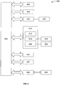
- An example of such a computer system 900 is shown in FIG. 9 .
- Computer system 900 includes at least one processor 904.
- Processor 904 is connected to a communication infrastructure 906 (e.g ., a communications bus, a cross-over bar device, or a network).
- a communication infrastructure 906 e.g ., a communications bus, a cross-over bar device, or a network.
- Computer system 900 includes a display interface (or other output interface) 902 that forwards graphics, text, and other data from communication infrastructure 906 (or from a frame buffer (not shown)) for display on a display unit (or other output unit) 930.
- display interface or other output interface
- Communication infrastructure 906 or from a frame buffer (not shown)
- display unit or other output unit
- Computer system 900 also includes a main memory 908, which preferably is a random access memory (RAM), and may also include a secondary memory 910.
- Secondary memory 910 may include, for example, a hard disk drive 912 and/or a removable-storage drive 914 (e.g ., a floppy disk drive, a magnetic tape drive, an optical disk drive, and the like).
- Removable-storage drive 914 reads from and/or writes to a removable storage unit 918 in a well-known manner.
- Removable storage unit 918 may be, for example, a floppy disk, a magnetic tape, an optical disk, and the like, which is written to and read from by removable-storage drive 914.
- Removable storage unit 918 can include a computer-usable storage medium having stored therein computer software and/or data.
- Computer system 900 also includes a camera unit 932 (e.g ., camera unit 114 of FIG. 1A ) that captures images and produces image data which is provided to the processor 904, the main memory 908, and/or the secondary memory 910.
- the computer system 900 includes a measuring unit 934 (e.g ., measuring unit 104 of FIG. 1A ) that acquires measurement data that is provided to the processor 904, the main memory 908, and/or the secondary memory 910.
- secondary memory 910 may include other similar devices for allowing computer programs or other instructions to be loaded into computer system 900.
- Such devices may include a removable storage unit 922 and an interface 920 (e.g., a program cartridge and a cartridge interface similar to those used with video game systems); a removable memory chip (e.g ., an erasable programmable read-only memory (“EPROM”) or a programmable read-only memory (“PROM”)) and an associated memory socket; and other removable storage units 922 and interfaces 920 that allow software and data to be transferred from removable storage unit 922 to computer system 900.
- EPROM erasable programmable read-only memory
- PROM programmable read-only memory
- Computer system 900 may also include a communications interface 924, which enables software and data to be transferred between computer system 900 and external devices (not shown).
- communications interface 924 may include a modem, a network interface (e.g ., an Ethernet card), a communications port (e.g ., a Universal Serial Bus (USB) port or a FireWire® port), a Personal Computer Memory Card International Association (“PCMCIA”) interface, and the like.
- Software and data transferred via communications interface 924 are in the form of signals, which may be electronic, electromagnetic, optical or another type of signal that is capable of being transmitted and/or received by communications interface 924.
- Signals are provided to communications interface 924 via a communications path 926 (e.g ., a channel).
- Communications path 926 carries signals and may be implemented using wire or cable, fiber optics, a telephone line, a cellular link, a radio-frequency (“RF”) link, or the like.
- RF radio-frequency
- computer program medium and “computer usable medium” may be used to generally refer to removable storage unit 918 used with removable-storage drive 914, a hard disk installed in hard disk drive 912, and signals, for example.
- These computer program products provide software to computer system 900.
- the present invention may be implemented or embodied as one or more of such computer program products.
- Computer programs are stored in main memory 908 and/or secondary memory 910. The computer programs may also be received via communications interface 924. Such computer programs, when executed, enable computer system 900 to perform the functions of the present invention, as described herein and shown in, for example, FIG. 2 . In particular, the computer programs, when executed, enable the processor 904 to perform the functions of the present invention. Accordingly, such computer programs represent controllers of computer system 900.
- the software may be stored in a computer program product and loaded into computer system 900 using removable-storage drive 914, hard drive 912, or communications interface 924.
- the control logic when executed by processor 904, causes processor 904 to perform the functions of the present invention described herein.
- the present invention is implemented primarily in hardware using, for example, hardware components such as application-specific integrated circuits ("ASICs").
- ASICs application-specific integrated circuits
- the present invention is implemented using a combination of both hardware and software.
- the present invention may be implemented using a single computer or using a computer system that includes multiple computers each programmed with control logic to perform various of the above-described functions of the present invention.
- a camera unit acquires two-dimensional image data of a lower surface of an object holder, and wherein spatial characteristics are determined based thereon.
- the present disclosure and invention are not limited to that functionality only. Indeed, it is within the scope of the invention to determine the applicable spatial characteristics based on images taken of other parts of the object holder and/or optical coding pattern, such as, for example, one or more sides thereof.
- One skilled in the art will appreciate, in view of the present disclosure, how to adapt the various steps of the method(s) described above, if at all, to obtain spatial characteristics based on the obtained images.
Landscapes
- Physics & Mathematics (AREA)
- General Physics & Mathematics (AREA)
- Engineering & Computer Science (AREA)
- Computer Vision & Pattern Recognition (AREA)
- Theoretical Computer Science (AREA)
- Length Measuring Devices By Optical Means (AREA)
- Image Analysis (AREA)
Claims (15)
- Procédé d'évaluation d'un objet disposé sur une surface supérieure d'un porte-objet, le procédé comprenant :- l'acquisition d'au moins une première trame représentant une partie capturée de l'objet disposé sur la surface supérieure du porte-objet, tandis que le porte-objet est positionné successivement à chacun des emplacements d'une pluralité d'emplacements ;- l'acquisition d'au moins un seconde trame représentant une partie capturée d'au moins une autre surface du porte-objet tandis que le porte-objet est positionné à chacun des emplacements de la pluralité d'emplacements, l'au moins une autre surface du porte-objet étant une surface inférieure du porte-objet ; et- la détermination d'au moins une caractéristique spatiale associée à la partie capturée de l'objet, en fonction d'au moins une des trames acquises.
- Procédé selon la revendication 1, comprenant en outre :
la création de données composites en fonction des trames acquises. - Procédé selon la revendication 1, dans lequel la détermination comprend :- pour chaque seconde trame, la détermination d'une orientation et des coordonnées associées à la partie capturée de l'au moins une autre surface du porte-objet ; et- ou chaque première trame, la traduction des coordonnées associées à la partie capturée de l'objet, en fonction de l'orientation et des coordonnées déterminées pour une seconde trame correspondante.
- Procédé selon la revendication 3, dans lequel l'au moins une autre surface comprend au moins un marqueur optique et dans lequel la détermination de l'orientation et des coordonnées comprend :- la détermination d'une orientation d'au moins un marqueur optique capturé dans chaque seconde trame,- la détermination d'une valeur de l'au moins un marqueur optique capturé dans chaque seconde trame et- la détermination des coordonnées d'un point de référence associé à chaque seconde trame.
- Procédé selon la revendication 4, dans lequel le point de référence associé à chaque seconde trame représente un centre de la seconde trame.
- Procédé selon la revendication 4, comprenant en outre la traduction des coordonnées du point de référence associé à chaque seconde trame en un système de coordonnées de référence.
- Procédé selon la revendication 1, dans lequel l'acquisition de chaque première trame est effectuée par mesure des optiques agencées pour acquérir des données tridimensionnelles et l'acquisition de chaque seconde trame est effectuée par une unité de caméra agencée pour acquérir des données d'images bidimensionnelles.
- Système d'évaluation d'un objet disposé sur une surface supérieure d'un porte-objet, l'appareil comprenant :une unité de mesure, agencée pour acquérir au moins une première trame représentant une partie capturée de l'objet disposé sur la surface supérieure du porte-objet, tandis que le porte-objet est positionné séquentiellement à chacun des emplacements d'une pluralité d'emplacements ;une unité de caméra, agencée pour acquérir au moins un seconde trame représentant une partie capturée d'au moins une autre surface du porte-objet tandis que le porte-objet est positionné à chacun des emplacements de la pluralité d'emplacements, l'au moins une autre surface du porte-objet étant une surface inférieure du porte-objet ; etune unité de traitement, utilisable pour déterminer au moins une caractéristique spatiale associée à la partie capturée de l'objet, en fonction d'au moins une des trames acquises.
- Système selon la revendication 8, dans lequel pour chaque seconde trame, l'unité de traitement est également utilisable pour déterminer une orientation et des coordonnées associées à la partie capturée de l'au moins une autre surface du porte-objet et dans lequel l'unité de traitement est en outre utilisable pour traduire, pour chaque première trame, les coordonnées associées à la partie capturée de l'objet, en fonction de l'orientation et des coordonnées déterminées pour une seconde trame correspondante.
- Système selon la revendication 8,
dans lequel l'au moins une autre surface comprend au moins un marqueur optique et dans lequel, pour chaque seconde trame, l'unité de traitement est également utilisable pour déterminer une orientation d'au moins un marqueur optique capturé dans chaque seconde trame, pour déterminer une valeur de l'au moins un marqueur optique capturé dans chaque seconde trame et pour déterminer les coordonnées d'un point de référence associé à chaque seconde trame. - Système selon la revendication 10, dans lequel le point de référence associé à chaque seconde trame représente un centre de la seconde trame.
- Système selon la revendication 10, dans lequel l'au moins un marqueur optique comprend un nombre et/ou un code-barres et/ou un rayon d'un cercle.
- Système selon la revendication 10, dans lequel l'unité de traitement est également utilisable pour traduire les coordonnées du point de référence associé à chaque seconde trame en un système de coordonnées de référence.
- Système selon la revendication 8, dans lequel l'unité de mesure comprend des optiques de mesure permettant d'acquérir des données de mesure en trois dimensions et l'unité de caméra acquiert des données d'images bidimensionnelles.
- Système selon la revendication 8, dans lequel un motif de codage optique comprenant plusieurs marqueurs optiques est formé sur l'au moins une autre surface du porte-objet.
Applications Claiming Priority (1)
| Application Number | Priority Date | Filing Date | Title |
|---|---|---|---|
| US12/137,338 US8121389B2 (en) | 2008-06-11 | 2008-06-11 | System, apparatus, method and computer program product for optical position recognition |
Publications (3)
| Publication Number | Publication Date |
|---|---|
| EP2136334A2 EP2136334A2 (fr) | 2009-12-23 |
| EP2136334A3 EP2136334A3 (fr) | 2016-09-07 |
| EP2136334B1 true EP2136334B1 (fr) | 2020-04-01 |
Family
ID=41269201
Family Applications (1)
| Application Number | Title | Priority Date | Filing Date |
|---|---|---|---|
| EP09162261.3A Active EP2136334B1 (fr) | 2008-06-11 | 2009-06-09 | Système, appareil, procédé et produit de programme informatique pour reconnaissance de position optique |
Country Status (3)
| Country | Link |
|---|---|
| US (1) | US8121389B2 (fr) |
| EP (1) | EP2136334B1 (fr) |
| DK (1) | DK2136334T3 (fr) |
Families Citing this family (4)
| Publication number | Priority date | Publication date | Assignee | Title |
|---|---|---|---|---|
| US8121389B2 (en) * | 2008-06-11 | 2012-02-21 | Sirona Dental Systems Gmbh | System, apparatus, method and computer program product for optical position recognition |
| US8290240B2 (en) * | 2008-06-11 | 2012-10-16 | Sirona Dental Systems Gmbh | System, apparatus, method, and computer program product for determining spatial characteristics of an object using a camera and a search pattern |
| EP2936123B1 (fr) * | 2012-12-21 | 2018-08-22 | Quantum Dental Technologies Inc. | Appareil d'imagerie et d'analyse d'échantillons dentaires in vitro |
| JP2016506842A (ja) | 2013-02-20 | 2016-03-07 | ゲーツェー ヨーロッパ | 事前調整された歯科インプラント補助器具 |
Family Cites Families (19)
| Publication number | Priority date | Publication date | Assignee | Title |
|---|---|---|---|---|
| US4145803A (en) * | 1977-07-22 | 1979-03-27 | Texas Instruments Incorporated | Lithographic offset alignment techniques for RAM fabrication |
| CH672722A5 (fr) * | 1986-06-24 | 1989-12-29 | Marco Brandestini | |
| DE69520511T2 (de) * | 1994-08-25 | 2001-08-23 | Trw Lucas Varity Electric Steering Ltd., Solihull | Capteur de deplacement et capteur de couple |
| US5523941A (en) * | 1994-10-04 | 1996-06-04 | Burton; Gary L. | X-Y-theta positioning mechanism |
| US5852675A (en) * | 1995-04-14 | 1998-12-22 | Kiyoshi Matsuo | Color chart for image correction and method of color correction |
| EP0865931B1 (fr) * | 1997-03-21 | 2002-09-04 | Canon Kabushiki Kaisha | Procédé pour la fabrication d'un substrat imprimé, élément émetteur d'électrons, source d'électrons et dispositif pour former des images |
| DE19829278C1 (de) * | 1998-06-30 | 2000-02-03 | Sirona Dental Systems Gmbh | 3-D-Kamera zur Erfassung von Oberflächenstrukturen, insbesondere für zahnmedizinische Zwecke |
| US6851949B1 (en) * | 1999-11-30 | 2005-02-08 | Orametrix, Inc. | Method and apparatus for generating a desired three-dimensional digital model of an orthodontic structure |
| JP3735344B2 (ja) * | 2002-12-27 | 2006-01-18 | オリンパス株式会社 | キャリブレーション装置、キャリブレーション方法、及びキャリブレーション用プログラム |
| DE102004054876B3 (de) * | 2004-11-12 | 2006-07-27 | Sirona Dental Systems Gmbh | Vermessungseinrichtung zur 3D-Vermessung von Zahnmodellen, Verschiebeplatte und Verfahren dazu |
| US8073528B2 (en) * | 2007-09-30 | 2011-12-06 | Intuitive Surgical Operations, Inc. | Tool tracking systems, methods and computer products for image guided surgery |
| CA2556533A1 (fr) * | 2005-08-24 | 2007-02-24 | Degudent Gmbh | Methode pour la determination de la forme d'une technologie dentaire et appareil utilisant cette methode |
| US20070091174A1 (en) * | 2005-09-30 | 2007-04-26 | Topcon Corporation | Projection device for three-dimensional measurement, and three-dimensional measurement system |
| JP5084167B2 (ja) * | 2006-03-31 | 2012-11-28 | キヤノン株式会社 | 位置姿勢計測方法及び装置 |
| JP2008014940A (ja) * | 2006-06-08 | 2008-01-24 | Fast:Kk | 平面状被撮像物のカメラ計測のためのカメラキャリブレーション方法、および応用計測装置 |
| JP5036260B2 (ja) * | 2006-09-14 | 2012-09-26 | キヤノン株式会社 | 位置姿勢算出方法及び装置 |
| US7256899B1 (en) * | 2006-10-04 | 2007-08-14 | Ivan Faul | Wireless methods and systems for three-dimensional non-contact shape sensing |
| US8121389B2 (en) * | 2008-06-11 | 2012-02-21 | Sirona Dental Systems Gmbh | System, apparatus, method and computer program product for optical position recognition |
| US8290240B2 (en) * | 2008-06-11 | 2012-10-16 | Sirona Dental Systems Gmbh | System, apparatus, method, and computer program product for determining spatial characteristics of an object using a camera and a search pattern |
-
2008
- 2008-06-11 US US12/137,338 patent/US8121389B2/en active Active
-
2009
- 2009-06-09 EP EP09162261.3A patent/EP2136334B1/fr active Active
- 2009-06-09 DK DK09162261.3T patent/DK2136334T3/da active
Non-Patent Citations (1)
| Title |
|---|
| H. KATO ET AL: "Marker tracking and HMD calibration for a video-based augmented reality conferencing system", AUGMENTED REALITY, 1999. (IWAR '99). PROCEEDINGS. 2ND IEEE AND ACM INT ERNATIONAL WORKSHOP ON SAN FRANCISCO, CA, USA 20-21 OCT. 1999, 1 January 1999 (1999-01-01), US, pages 85 - 94, XP055370372, ISBN: 978-0-7695-0359-2, DOI: 10.1109/IWAR.1999.803809 * |
Also Published As
| Publication number | Publication date |
|---|---|
| DK2136334T3 (da) | 2020-07-13 |
| EP2136334A3 (fr) | 2016-09-07 |
| US20090310146A1 (en) | 2009-12-17 |
| EP2136334A2 (fr) | 2009-12-23 |
| US8121389B2 (en) | 2012-02-21 |
Similar Documents
| Publication | Publication Date | Title |
|---|---|---|
| JP7218435B2 (ja) | キャリブレーション装置、キャリブレーション用チャート、およびキャリブレーション方法 | |
| US7733404B2 (en) | Fast imaging system calibration | |
| JP4757142B2 (ja) | 撮影環境校正方法及び情報処理装置 | |
| JP4708752B2 (ja) | 情報処理方法および装置 | |
| EP2272047B1 (fr) | Système de formation d images 3d | |
| US7742635B2 (en) | Artifact mitigation in three-dimensional imaging | |
| US9240048B2 (en) | Depth estimation using three-dimensional epipolar data structures | |
| EP2551633B1 (fr) | Procédé et dispositif de mesure de distance en trois dimensions | |
| WO2010095107A1 (fr) | Système et procédé de modélisation géométrique utilisant de multiples moyens d'acquisition de données | |
| JP2000227309A (ja) | 3次元位置姿勢センシング装置 | |
| KR20180105875A (ko) | 단일 영상을 이용한 카메라 캘리브레이션 방법 및 이를 위한 장치 | |
| EP2136334B1 (fr) | Système, appareil, procédé et produit de programme informatique pour reconnaissance de position optique | |
| WO2015066756A1 (fr) | Étalonnage d'un microscope 3d | |
| JP2020126208A (ja) | 3次元画像表示方法、3次元画像表示装置、およびプログラム | |
| EP2192378B1 (fr) | Système, appareil, procédé et produit de programme informatique pour déterminer les caractéristiques spatiales d'un objet en utilisant une caméra et un motif de recherche | |
| CN115856797A (zh) | 一种传感器标定方法及装置 | |
| JP5841310B2 (ja) | カメラ及び検索パターンを使用して対象物の空間特性を決定するためのシステム、装置、方法、及びコンピュータプログラム製品 | |
| Jarron et al. | Automatic detection and labelling of photogrammetric control points in a calibration test field | |
| CN115813431A (zh) | 多深度超声探头标定的方法、装置及系统 | |
| JP4226452B2 (ja) | 光学式手術用ナビゲーションシステム及び方法とそれに用いられる反射球マーカ | |
| JP4196784B2 (ja) | カメラ位置測定装置および方法並びにカメラ位置制御方法 | |
| JP2009251659A (ja) | 画像処理装置、画像処理プログラム、画像処理方法、および電子機器 | |
| JPH09229648A (ja) | 画像情報入出力装置及び画像情報入出力方法 | |
| JP4804125B2 (ja) | 2次元コード、2次元コード検出方法、および2次元コード検出装置 | |
| CN121236126A (zh) | 配准方法、装置、系统及电子设备 |
Legal Events
| Date | Code | Title | Description |
|---|---|---|---|
| PUAI | Public reference made under article 153(3) epc to a published international application that has entered the european phase |
Free format text: ORIGINAL CODE: 0009012 |
|
| AK | Designated contracting states |
Kind code of ref document: A2 Designated state(s): AT BE BG CH CY CZ DE DK EE ES FI FR GB GR HR HU IE IS IT LI LT LU LV MC MK MT NL NO PL PT RO SE SI SK TR |
|
| TPAC | Observations filed by third parties |
Free format text: ORIGINAL CODE: EPIDOSNTIPA |
|
| PUAL | Search report despatched |
Free format text: ORIGINAL CODE: 0009013 |
|
| AK | Designated contracting states |
Kind code of ref document: A3 Designated state(s): AT BE BG CH CY CZ DE DK EE ES FI FR GB GR HR HU IE IS IT LI LT LU LV MC MK MT NL NO PL PT RO SE SI SK TR |
|
| RIC1 | Information provided on ipc code assigned before grant |
Ipc: G01B 11/00 20060101ALI20160803BHEP Ipc: G06T 7/00 20060101AFI20160803BHEP |
|
| STAA | Information on the status of an ep patent application or granted ep patent |
Free format text: STATUS: REQUEST FOR EXAMINATION WAS MADE |
|
| 17P | Request for examination filed |
Effective date: 20170207 |
|
| RBV | Designated contracting states (corrected) |
Designated state(s): AT BE BG CH CY CZ DE DK EE ES FI FR GB GR HR HU IE IS IT LI LT LU LV MC MK MT NL NO PL PT RO SE SI SK TR |
|
| STAA | Information on the status of an ep patent application or granted ep patent |
Free format text: STATUS: EXAMINATION IS IN PROGRESS |
|
| 17Q | First examination report despatched |
Effective date: 20190415 |
|
| REG | Reference to a national code |
Ref country code: DE Ref legal event code: R079 Ref document number: 602009061580 Country of ref document: DE Free format text: PREVIOUS MAIN CLASS: G06T0007000000 Ipc: G01B0011240000 |
|
| RIC1 | Information provided on ipc code assigned before grant |
Ipc: G06T 7/33 20170101ALI20191127BHEP Ipc: G01B 11/24 20060101AFI20191127BHEP |
|
| GRAP | Despatch of communication of intention to grant a patent |
Free format text: ORIGINAL CODE: EPIDOSNIGR1 |
|
| STAA | Information on the status of an ep patent application or granted ep patent |
Free format text: STATUS: GRANT OF PATENT IS INTENDED |
|
| INTG | Intention to grant announced |
Effective date: 20200103 |
|
| GRAS | Grant fee paid |
Free format text: ORIGINAL CODE: EPIDOSNIGR3 |
|
| GRAA | (expected) grant |
Free format text: ORIGINAL CODE: 0009210 |
|
| STAA | Information on the status of an ep patent application or granted ep patent |
Free format text: STATUS: THE PATENT HAS BEEN GRANTED |
|
| AK | Designated contracting states |
Kind code of ref document: B1 Designated state(s): AT BE BG CH CY CZ DE DK EE ES FI FR GB GR HR HU IE IS IT LI LT LU LV MC MK MT NL NO PL PT RO SE SI SK TR |
|
| REG | Reference to a national code |
Ref country code: GB Ref legal event code: FG4D |
|
| REG | Reference to a national code |
Ref country code: CH Ref legal event code: EP Ref country code: AT Ref legal event code: REF Ref document number: 1251917 Country of ref document: AT Kind code of ref document: T Effective date: 20200415 |
|
| REG | Reference to a national code |
Ref country code: DE Ref legal event code: R096 Ref document number: 602009061580 Country of ref document: DE |
|
| REG | Reference to a national code |
Ref country code: IE Ref legal event code: FG4D |
|
| REG | Reference to a national code |
Ref country code: CH Ref legal event code: NV Representative=s name: DENNEMEYER AG, CH |
|
| REG | Reference to a national code |
Ref country code: DK Ref legal event code: T3 Effective date: 20200707 |
|
| PG25 | Lapsed in a contracting state [announced via postgrant information from national office to epo] |
Ref country code: BG Free format text: LAPSE BECAUSE OF FAILURE TO SUBMIT A TRANSLATION OF THE DESCRIPTION OR TO PAY THE FEE WITHIN THE PRESCRIBED TIME-LIMIT Effective date: 20200701 |
|
| REG | Reference to a national code |
Ref country code: NL Ref legal event code: MP Effective date: 20200401 |
|
| REG | Reference to a national code |
Ref country code: LT Ref legal event code: MG4D |
|
| PG25 | Lapsed in a contracting state [announced via postgrant information from national office to epo] |
Ref country code: LT Free format text: LAPSE BECAUSE OF FAILURE TO SUBMIT A TRANSLATION OF THE DESCRIPTION OR TO PAY THE FEE WITHIN THE PRESCRIBED TIME-LIMIT Effective date: 20200401 Ref country code: GR Free format text: LAPSE BECAUSE OF FAILURE TO SUBMIT A TRANSLATION OF THE DESCRIPTION OR TO PAY THE FEE WITHIN THE PRESCRIBED TIME-LIMIT Effective date: 20200702 Ref country code: CZ Free format text: LAPSE BECAUSE OF FAILURE TO SUBMIT A TRANSLATION OF THE DESCRIPTION OR TO PAY THE FEE WITHIN THE PRESCRIBED TIME-LIMIT Effective date: 20200401 Ref country code: NL Free format text: LAPSE BECAUSE OF FAILURE TO SUBMIT A TRANSLATION OF THE DESCRIPTION OR TO PAY THE FEE WITHIN THE PRESCRIBED TIME-LIMIT Effective date: 20200401 Ref country code: PT Free format text: LAPSE BECAUSE OF FAILURE TO SUBMIT A TRANSLATION OF THE DESCRIPTION OR TO PAY THE FEE WITHIN THE PRESCRIBED TIME-LIMIT Effective date: 20200817 Ref country code: SE Free format text: LAPSE BECAUSE OF FAILURE TO SUBMIT A TRANSLATION OF THE DESCRIPTION OR TO PAY THE FEE WITHIN THE PRESCRIBED TIME-LIMIT Effective date: 20200401 Ref country code: IS Free format text: LAPSE BECAUSE OF FAILURE TO SUBMIT A TRANSLATION OF THE DESCRIPTION OR TO PAY THE FEE WITHIN THE PRESCRIBED TIME-LIMIT Effective date: 20200801 Ref country code: NO Free format text: LAPSE BECAUSE OF FAILURE TO SUBMIT A TRANSLATION OF THE DESCRIPTION OR TO PAY THE FEE WITHIN THE PRESCRIBED TIME-LIMIT Effective date: 20200701 Ref country code: FI Free format text: LAPSE BECAUSE OF FAILURE TO SUBMIT A TRANSLATION OF THE DESCRIPTION OR TO PAY THE FEE WITHIN THE PRESCRIBED TIME-LIMIT Effective date: 20200401 |
|
| PG25 | Lapsed in a contracting state [announced via postgrant information from national office to epo] |
Ref country code: LV Free format text: LAPSE BECAUSE OF FAILURE TO SUBMIT A TRANSLATION OF THE DESCRIPTION OR TO PAY THE FEE WITHIN THE PRESCRIBED TIME-LIMIT Effective date: 20200401 Ref country code: HR Free format text: LAPSE BECAUSE OF FAILURE TO SUBMIT A TRANSLATION OF THE DESCRIPTION OR TO PAY THE FEE WITHIN THE PRESCRIBED TIME-LIMIT Effective date: 20200401 |
|
| REG | Reference to a national code |
Ref country code: DE Ref legal event code: R097 Ref document number: 602009061580 Country of ref document: DE |
|
| PG25 | Lapsed in a contracting state [announced via postgrant information from national office to epo] |
Ref country code: MC Free format text: LAPSE BECAUSE OF FAILURE TO SUBMIT A TRANSLATION OF THE DESCRIPTION OR TO PAY THE FEE WITHIN THE PRESCRIBED TIME-LIMIT Effective date: 20200401 Ref country code: RO Free format text: LAPSE BECAUSE OF FAILURE TO SUBMIT A TRANSLATION OF THE DESCRIPTION OR TO PAY THE FEE WITHIN THE PRESCRIBED TIME-LIMIT Effective date: 20200401 Ref country code: ES Free format text: LAPSE BECAUSE OF FAILURE TO SUBMIT A TRANSLATION OF THE DESCRIPTION OR TO PAY THE FEE WITHIN THE PRESCRIBED TIME-LIMIT Effective date: 20200401 Ref country code: EE Free format text: LAPSE BECAUSE OF FAILURE TO SUBMIT A TRANSLATION OF THE DESCRIPTION OR TO PAY THE FEE WITHIN THE PRESCRIBED TIME-LIMIT Effective date: 20200401 Ref country code: IT Free format text: LAPSE BECAUSE OF FAILURE TO SUBMIT A TRANSLATION OF THE DESCRIPTION OR TO PAY THE FEE WITHIN THE PRESCRIBED TIME-LIMIT Effective date: 20200401 |
|
| PLBE | No opposition filed within time limit |
Free format text: ORIGINAL CODE: 0009261 |
|
| STAA | Information on the status of an ep patent application or granted ep patent |
Free format text: STATUS: NO OPPOSITION FILED WITHIN TIME LIMIT |
|
| PG25 | Lapsed in a contracting state [announced via postgrant information from national office to epo] |
Ref country code: SK Free format text: LAPSE BECAUSE OF FAILURE TO SUBMIT A TRANSLATION OF THE DESCRIPTION OR TO PAY THE FEE WITHIN THE PRESCRIBED TIME-LIMIT Effective date: 20200401 Ref country code: PL Free format text: LAPSE BECAUSE OF FAILURE TO SUBMIT A TRANSLATION OF THE DESCRIPTION OR TO PAY THE FEE WITHIN THE PRESCRIBED TIME-LIMIT Effective date: 20200401 |
|
| 26N | No opposition filed |
Effective date: 20210112 |
|
| PG25 | Lapsed in a contracting state [announced via postgrant information from national office to epo] |
Ref country code: LU Free format text: LAPSE BECAUSE OF NON-PAYMENT OF DUE FEES Effective date: 20200609 |
|
| REG | Reference to a national code |
Ref country code: BE Ref legal event code: MM Effective date: 20200630 |
|
| PG25 | Lapsed in a contracting state [announced via postgrant information from national office to epo] |
Ref country code: IE Free format text: LAPSE BECAUSE OF NON-PAYMENT OF DUE FEES Effective date: 20200609 |
|
| PG25 | Lapsed in a contracting state [announced via postgrant information from national office to epo] |
Ref country code: SI Free format text: LAPSE BECAUSE OF FAILURE TO SUBMIT A TRANSLATION OF THE DESCRIPTION OR TO PAY THE FEE WITHIN THE PRESCRIBED TIME-LIMIT Effective date: 20200401 Ref country code: BE Free format text: LAPSE BECAUSE OF NON-PAYMENT OF DUE FEES Effective date: 20200630 |
|
| REG | Reference to a national code |
Ref country code: AT Ref legal event code: UEP Ref document number: 1251917 Country of ref document: AT Kind code of ref document: T Effective date: 20200401 |
|
| PG25 | Lapsed in a contracting state [announced via postgrant information from national office to epo] |
Ref country code: TR Free format text: LAPSE BECAUSE OF FAILURE TO SUBMIT A TRANSLATION OF THE DESCRIPTION OR TO PAY THE FEE WITHIN THE PRESCRIBED TIME-LIMIT Effective date: 20200401 Ref country code: MT Free format text: LAPSE BECAUSE OF FAILURE TO SUBMIT A TRANSLATION OF THE DESCRIPTION OR TO PAY THE FEE WITHIN THE PRESCRIBED TIME-LIMIT Effective date: 20200401 Ref country code: CY Free format text: LAPSE BECAUSE OF FAILURE TO SUBMIT A TRANSLATION OF THE DESCRIPTION OR TO PAY THE FEE WITHIN THE PRESCRIBED TIME-LIMIT Effective date: 20200401 |
|
| PG25 | Lapsed in a contracting state [announced via postgrant information from national office to epo] |
Ref country code: MK Free format text: LAPSE BECAUSE OF FAILURE TO SUBMIT A TRANSLATION OF THE DESCRIPTION OR TO PAY THE FEE WITHIN THE PRESCRIBED TIME-LIMIT Effective date: 20200401 |
|
| P01 | Opt-out of the competence of the unified patent court (upc) registered |
Effective date: 20230509 |
|
| PGFP | Annual fee paid to national office [announced via postgrant information from national office to epo] |
Ref country code: GB Payment date: 20240502 Year of fee payment: 16 |
|
| PGFP | Annual fee paid to national office [announced via postgrant information from national office to epo] |
Ref country code: DE Payment date: 20240502 Year of fee payment: 16 |
|
| PGFP | Annual fee paid to national office [announced via postgrant information from national office to epo] |
Ref country code: DK Payment date: 20240612 Year of fee payment: 16 |
|
| PGFP | Annual fee paid to national office [announced via postgrant information from national office to epo] |
Ref country code: AT Payment date: 20240529 Year of fee payment: 16 |
|
| PGFP | Annual fee paid to national office [announced via postgrant information from national office to epo] |
Ref country code: FR Payment date: 20240509 Year of fee payment: 16 |
|
| PGFP | Annual fee paid to national office [announced via postgrant information from national office to epo] |
Ref country code: CH Payment date: 20240701 Year of fee payment: 16 |
|
| REG | Reference to a national code |
Ref country code: CH Ref legal event code: H13 Free format text: ST27 STATUS EVENT CODE: U-0-0-H10-H13 (AS PROVIDED BY THE NATIONAL OFFICE) Effective date: 20260127 |