EP2136115A2 - Soupape de sécurité - Google Patents
Soupape de sécurité Download PDFInfo
- Publication number
- EP2136115A2 EP2136115A2 EP20090162691 EP09162691A EP2136115A2 EP 2136115 A2 EP2136115 A2 EP 2136115A2 EP 20090162691 EP20090162691 EP 20090162691 EP 09162691 A EP09162691 A EP 09162691A EP 2136115 A2 EP2136115 A2 EP 2136115A2
- Authority
- EP
- European Patent Office
- Prior art keywords
- closing element
- safety valve
- arm
- spring
- spring holder
- Prior art date
- Legal status (The legal status is an assumption and is not a legal conclusion. Google has not performed a legal analysis and makes no representation as to the accuracy of the status listed.)
- Granted
Links
- 238000007789 sealing Methods 0.000 claims abstract description 5
- 238000013459 approach Methods 0.000 description 2
- 230000005540 biological transmission Effects 0.000 description 2
- 238000006073 displacement reaction Methods 0.000 description 2
- 230000000694 effects Effects 0.000 description 2
- 230000002349 favourable effect Effects 0.000 description 2
- 239000007788 liquid Substances 0.000 description 2
- 229910000831 Steel Inorganic materials 0.000 description 1
- 239000002253 acid Substances 0.000 description 1
- 150000007513 acids Chemical class 0.000 description 1
- 230000015572 biosynthetic process Effects 0.000 description 1
- 238000010276 construction Methods 0.000 description 1
- 230000007797 corrosion Effects 0.000 description 1
- 238000005260 corrosion Methods 0.000 description 1
- 230000003111 delayed effect Effects 0.000 description 1
- 238000010586 diagram Methods 0.000 description 1
- 210000003746 feather Anatomy 0.000 description 1
- 239000003348 petrochemical agent Substances 0.000 description 1
- 239000007787 solid Substances 0.000 description 1
- 230000003068 static effect Effects 0.000 description 1
- 239000010959 steel Substances 0.000 description 1
- 238000009827 uniform distribution Methods 0.000 description 1
Images

Classifications
-
- F—MECHANICAL ENGINEERING; LIGHTING; HEATING; WEAPONS; BLASTING
- F16—ENGINEERING ELEMENTS AND UNITS; GENERAL MEASURES FOR PRODUCING AND MAINTAINING EFFECTIVE FUNCTIONING OF MACHINES OR INSTALLATIONS; THERMAL INSULATION IN GENERAL
- F16K—VALVES; TAPS; COCKS; ACTUATING-FLOATS; DEVICES FOR VENTING OR AERATING
- F16K17/00—Safety valves; Equalising valves, e.g. pressure relief valves
- F16K17/02—Safety valves; Equalising valves, e.g. pressure relief valves opening on surplus pressure on one side; closing on insufficient pressure on one side
- F16K17/04—Safety valves; Equalising valves, e.g. pressure relief valves opening on surplus pressure on one side; closing on insufficient pressure on one side spring-loaded
- F16K17/044—Safety valves; Equalising valves, e.g. pressure relief valves opening on surplus pressure on one side; closing on insufficient pressure on one side spring-loaded with more than one spring
-
- Y—GENERAL TAGGING OF NEW TECHNOLOGICAL DEVELOPMENTS; GENERAL TAGGING OF CROSS-SECTIONAL TECHNOLOGIES SPANNING OVER SEVERAL SECTIONS OF THE IPC; TECHNICAL SUBJECTS COVERED BY FORMER USPC CROSS-REFERENCE ART COLLECTIONS [XRACs] AND DIGESTS
- Y10—TECHNICAL SUBJECTS COVERED BY FORMER USPC
- Y10T—TECHNICAL SUBJECTS COVERED BY FORMER US CLASSIFICATION
- Y10T137/00—Fluid handling
- Y10T137/7722—Line condition change responsive valves
- Y10T137/7738—Pop valves
-
- Y—GENERAL TAGGING OF NEW TECHNOLOGICAL DEVELOPMENTS; GENERAL TAGGING OF CROSS-SECTIONAL TECHNOLOGIES SPANNING OVER SEVERAL SECTIONS OF THE IPC; TECHNICAL SUBJECTS COVERED BY FORMER USPC CROSS-REFERENCE ART COLLECTIONS [XRACs] AND DIGESTS
- Y10—TECHNICAL SUBJECTS COVERED BY FORMER USPC
- Y10T—TECHNICAL SUBJECTS COVERED BY FORMER US CLASSIFICATION
- Y10T137/00—Fluid handling
- Y10T137/7722—Line condition change responsive valves
- Y10T137/7837—Direct response valves [i.e., check valve type]
- Y10T137/7904—Reciprocating valves
- Y10T137/7907—Varying effective lever arm
-
- Y—GENERAL TAGGING OF NEW TECHNOLOGICAL DEVELOPMENTS; GENERAL TAGGING OF CROSS-SECTIONAL TECHNOLOGIES SPANNING OVER SEVERAL SECTIONS OF THE IPC; TECHNICAL SUBJECTS COVERED BY FORMER USPC CROSS-REFERENCE ART COLLECTIONS [XRACs] AND DIGESTS
- Y10—TECHNICAL SUBJECTS COVERED BY FORMER USPC
- Y10T—TECHNICAL SUBJECTS COVERED BY FORMER US CLASSIFICATION
- Y10T137/00—Fluid handling
- Y10T137/7722—Line condition change responsive valves
- Y10T137/7837—Direct response valves [i.e., check valve type]
- Y10T137/7904—Reciprocating valves
- Y10T137/7922—Spring biased
Definitions
- the invention relates to a safety valve having an inlet and an outlet and a closing element which seals the inlet and moves under pressure and thereby opens a path from the inlet to the outlet, wherein the closing element is connected by at least one arm with at least one spring element against which Force the closing element moves when opening.
- Today used safety valves are on the one hand high temperatures, for example in steam power plants currently up to 560 ° C, in the future up to 700 ° C, and high pressures up to 350 bar exposed and on the other hand z. B. in petrochemicals with extremely aggressive media such as acids come into contact.
- one or more springs are used for holding or moving back a closing element, wherein it is endeavored to position the sensitive to springs as far as possible or the given in a safety valve flow paths of the optionally aggressive and partly high-temperature media to protect the feathers.
- the object of the invention is to provide a safety valve of the type mentioned in such a way that this carries sufficient action on the closing element during its movement forces with a simple structure, so this already opens at low pressure, but without fluttering occurs during further opening.
- a safety valve of the type mentioned in which an arm is provided which connects closing element and spring element, wherein the arm is pivotally mounted on the closing element and the spring element about an axis and arranged around a further, between said axes Axis is pivotable and relative to this longitudinally displaceable.
- the arm can be mounted in any manner on the closing element or spring element about the provided axes pivotally.
- the arm it is expedient, however, for the arm to be pivotably mounted about the axes by means of bolts on the closing element and on the spring element.
- a longitudinal displacement of the arm at the same time with a pivoting about a further axis can be realized in a particularly simple manner when the arm has a slot into which engages another bolt on which the arm is mounted.
- the axes are arranged approximately in the region of ends of the arm, so that a compact or space-saving design is given.
- the inventive concept can be applied to various safety valves, it proves to be particularly useful if the closing element is elongated and formed with a preferably conical end piece which seals the inlet.
- the arm is then particularly preferably mounted on the end opposite the conical end of the closing element.
- a conical end piece can basically be provided a newly formed end piece.
- the spring element may be formed in different ways, provided that the closing element is acted upon by a desired spring force. It is favorable, however, if the spring element comprises a longitudinal body with an upper spring holder and a lower spring holder and a spring held between the upper spring holder and lower spring, wherein the longitudinal body passes through the lower spring holder and can slide through this and in the region of the lower spring holder projecting end or an associated extension is connected to the arm.
- the lower spring holder is preferably with a formed conical end. This makes it possible that the conical end of the lower spring holder can rest in an approximately semicircular groove, whereby the required pivotability of the spring element can be realized in a particularly simple manner when the closing element and thus the arm moves.
- a base body in which the closing element is arranged and the base body has a cover plate or another suitably shaped receptacle with a recess through which the projecting end of the longitudinal body passes.
- a bearing surface for the spring element is given in a simple manner and the longitudinal body can move substantially without friction and tilt the spring element as needed.
- the spring element at a sealing position of the closing element substantially vertically and tilts only upon movement of the closing element or during movement of the arm.
- the closing element may in particular be designed to be vertically movable, although the closing element may also be movable in another way.
- a safety valve according to the invention several, preferably two to four, spring elements may be provided. This proves to be particularly favorable when a low height of the safety valve is desired.
- the individual spring elements are arranged in a plan view of the safety valve preferably rotationally symmetrical about the closing element.
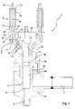
- FIG. 1 an inventive safety valve 1 according to an embodiment of the invention is shown.
- the safety valve 1 comprises a main body 24 with an inlet 2 and an outlet 3.
- the inlet 2 is connected to a line in which a liquid, in particular an aggressive medium, which for example has a temperature of 300 ° C, is transported.
- the inlet 2 is sealed by a closing element 4 of the safety valve 1, wherein a conical end piece 14 of the closing element 4 provides the seal.
- a pressure of a liquid transported in a line is too low to move the closing element 4 from the position shown.
- the elongated closing element 4 has, following the conical end piece 14, a cylindrical part 28 which may be hollow or solid. Subsequent to the cylindrical part 28, the closing element 4 is formed tapered, but two sliding portions 29 are provided, the outer diameter of which corresponds to that of the cylindrical portion 28. These sliding portions 29 are arranged between the cylindrical part 28 and the conical end piece 14 opposite end 15.
- the closing element 4 is held vertically movable in a seat 25.
- the seat 25 is in turn encompassed by the main body 24, in which the inlet 2 and the outlet 3 extend.
- the closing element 4 is surrounded by a T-piece 31 in the region of the end 15 opposite the conical end piece 14.
- an arm 5 is pivotally mounted about an axis 8, wherein a bolt 11 is provided for the pivotable mounting.
- the arm 5, which consists for example of steel, is in Essentially rigid and straight and formed at its other end to a spring element 6 about an axis 7 also pivotally mounted, in turn, a bolt 10 is provided for storage.
- the arm 5, which is in the in Fig. 1 shown situation can be made approximately at an angle of 30 ° to 75 ° to the closing element 4, approximately centered about a further axis 9 pivotally mounted, again for the storage of a bolt 12 is used.
- the arm 5 is not only pivotable, but because a slot 13 is provided, also relative to the axis 9 to this slidably. In the region of the slot 13, the arm 5 may be surface hardened, so that a high resistance to wear is given.
- the bolt 10, on which the arm 5 is mounted to connect the spring element 6 with the closing element 4, is part of an extension 21 of the spring element 6.
- the spring element 6 consists of a projection 21 connected to the longitudinal body 16, with a projecting End 20 passes through a recess 27 through the cover plate 26 and on the opposite side of the cover plate 26 comprises an upper spring holder 17, a lower spring holder 18 and a spring 19 located therebetween.
- the lower pen holder 18 is located in an in Fig. 1 not visible groove 23 of the cover plate 26, with a conical end 22.
- the longitudinal body 16 can by the lower spring holder 18 which rests as mentioned on the cover plate 26, slide, wherein the spring 19 is further tensioned.
- a maximum tilt angle of the spring element 6 is about 30 °. If a plurality of spring elements 6 are provided for a single closing element 4, which is advantageous in relation to a low overall height of the entire safety valve 1, the spring elements 6 are arranged so that they do not touch each other at the maximum tilt angle. With regard to a space-saving design, tilt angles of less than 10 ° are preferred.
- Fig. 3 It is shown how the inventive design of a safety valve 1 affects the given at the conical end piece 14 of the closing element 4 forces. While in a spring or a spring element with a linear characteristic curve, the characteristic shown in line A is obtained, the obtained with a safety valve 1 according to the invention power flow according to line B is variable. As in Fig. 3 it can be seen, at the beginning of a stroke of the closing element 4, a force is lower relative to a force of a spring with a linear characteristic. D. h. That the closing element 4 opens already at a lower force or at a lower pressure in a line.
- the force acting on the closing element 4 or the conical end piece 14 increases more with increasing stroke in comparison with a spring with a linear characteristic, so that the closing element 4 is slowed down after opening and further movement by the now increasing force, which is why it finally gently approaches an end position, in which the force can then decrease due to execution.
- a flutter is at least largely, ideally completely, avoided.
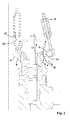
- Fig. 4 it is schematically illustrated how the lever ratios change due to the longitudinally displaceable arm 5 of the safety valve 1 according to the invention during an upward movement of the closing element 4.
- the sequence (from left to right) of a sealing position of the closure member 4 over a half-open position to a fully open position can by a combination of pivoting and longitudinal displacement of the arm 5 the forces F s acting during a movement of the closing element 4 are specifically taken into account by means of variable opposing forces F F.
Landscapes
- Engineering & Computer Science (AREA)
- General Engineering & Computer Science (AREA)
- Mechanical Engineering (AREA)
- Safety Valves (AREA)
Applications Claiming Priority (1)
| Application Number | Priority Date | Filing Date | Title |
|---|---|---|---|
| AT0097208A AT506990B1 (de) | 2008-06-18 | 2008-06-18 | Sicherheitsventil |
Publications (3)
| Publication Number | Publication Date |
|---|---|
| EP2136115A2 true EP2136115A2 (fr) | 2009-12-23 |
| EP2136115A3 EP2136115A3 (fr) | 2010-09-29 |
| EP2136115B1 EP2136115B1 (fr) | 2011-12-14 |
Family
ID=40974598
Family Applications (1)
| Application Number | Title | Priority Date | Filing Date |
|---|---|---|---|
| EP20090162691 Not-in-force EP2136115B1 (fr) | 2008-06-18 | 2009-06-15 | Soupape de sécurité |
Country Status (3)
| Country | Link |
|---|---|
| US (1) | US8479764B2 (fr) |
| EP (1) | EP2136115B1 (fr) |
| AT (2) | AT506990B1 (fr) |
Families Citing this family (1)
| Publication number | Priority date | Publication date | Assignee | Title |
|---|---|---|---|---|
| US11554461B1 (en) | 2018-02-13 | 2023-01-17 | Omax Corporation | Articulating apparatus of a waterjet system and related technology |
Citations (7)
| Publication number | Priority date | Publication date | Assignee | Title |
|---|---|---|---|---|
| US58962A (en) | 1866-10-16 | Improvement in steam safety-valves | ||
| US2973777A (en) | 1959-03-20 | 1961-03-07 | Cameron Iron Works Inc | Pressure relief valve |
| SU723260A1 (ru) | 1977-12-19 | 1980-03-25 | Предприятие П/Я А-7899 | Предохранительный клапан |
| US4201242A (en) | 1978-06-13 | 1980-05-06 | Cameron Iron Works, Inc. | Pressure relief valve |
| JPH08121626A (ja) | 1994-10-18 | 1996-05-17 | Toshiba Corp | 主蒸気逃がし安全弁 |
| US5909748A (en) | 1998-05-26 | 1999-06-08 | Lacroix; Barry | Pressure relief valve |
| DE19860578A1 (de) | 1998-12-29 | 2000-07-06 | Asea Brown Boveri | Federbelastetes Sicherheitsventil |
Family Cites Families (6)
| Publication number | Priority date | Publication date | Assignee | Title |
|---|---|---|---|---|
| DE5369C (de) * | A. SCHJIID in Zürich | Sicherheitsventil | ||
| US1408603A (en) * | 1917-09-17 | 1922-03-07 | Luftfahrzeugbau Schutte Lanz | Deflating and safety valve for gas-filled balloons |
| DE1163100B (de) | 1958-11-03 | 1964-02-13 | Gerdts Gustav F Kg | Absperrventil, insbesondere Fuell- und Entleerungsventil fuer Kesselwagen |
| US3229713A (en) * | 1962-11-06 | 1966-01-18 | Charles W Wiegand | Pressure control valve |
| FR1468643A (fr) | 1963-11-29 | 1967-02-10 | Perfectionnement aux détendeurs régulateurs de pression, à action directe, notamment pour des fluides gazeux sous moyenne et haute pression | |
| SU1046565A1 (ru) * | 1981-12-21 | 1983-10-07 | Предприятие П/Я А-7899 | Предохранительный клапан |
-
2008
- 2008-06-18 AT AT0097208A patent/AT506990B1/de not_active IP Right Cessation
-
2009
- 2009-06-15 EP EP20090162691 patent/EP2136115B1/fr not_active Not-in-force
- 2009-06-15 AT AT09162691T patent/ATE537394T1/de active
- 2009-06-17 US US12/486,286 patent/US8479764B2/en not_active Expired - Fee Related
Patent Citations (7)
| Publication number | Priority date | Publication date | Assignee | Title |
|---|---|---|---|---|
| US58962A (en) | 1866-10-16 | Improvement in steam safety-valves | ||
| US2973777A (en) | 1959-03-20 | 1961-03-07 | Cameron Iron Works Inc | Pressure relief valve |
| SU723260A1 (ru) | 1977-12-19 | 1980-03-25 | Предприятие П/Я А-7899 | Предохранительный клапан |
| US4201242A (en) | 1978-06-13 | 1980-05-06 | Cameron Iron Works, Inc. | Pressure relief valve |
| JPH08121626A (ja) | 1994-10-18 | 1996-05-17 | Toshiba Corp | 主蒸気逃がし安全弁 |
| US5909748A (en) | 1998-05-26 | 1999-06-08 | Lacroix; Barry | Pressure relief valve |
| DE19860578A1 (de) | 1998-12-29 | 2000-07-06 | Asea Brown Boveri | Federbelastetes Sicherheitsventil |
Also Published As
| Publication number | Publication date |
|---|---|
| EP2136115B1 (fr) | 2011-12-14 |
| EP2136115A3 (fr) | 2010-09-29 |
| AT506990B1 (de) | 2010-11-15 |
| AT506990A1 (de) | 2010-01-15 |
| US8479764B2 (en) | 2013-07-09 |
| ATE537394T1 (de) | 2011-12-15 |
| US20090320938A1 (en) | 2009-12-31 |
Similar Documents
| Publication | Publication Date | Title |
|---|---|---|
| DE102017007236B4 (de) | Drosselventil mit proportionalem Überlauf | |
| EP1978304B1 (fr) | Système de verrouillage pour sections transversales de conduites de grande taille à l'aide d'un clapet basculant | |
| EP1818491A2 (fr) | Ferrure pour un volet de meuble | |
| DE2449857C3 (de) | Rückschlagarmatur ffir Rohrleitungen | |
| DE3723120A1 (de) | Automatisch gesteuertes servoventil mit schnelloeffnung | |
| DE102012209031B4 (de) | Absperrschieber | |
| CH700776B1 (de) | Plattenschieber, insbesondere zum Absperren einer Medien führenden Leitung. | |
| EP2136115B1 (fr) | Soupape de sécurité | |
| EP1637783B1 (fr) | Combinaison de soupape pour turbine à vapeur avec une soupape à fermeture rapide et une soupape de régulation | |
| DE20312986U1 (de) | Strömungswächter zum automatischen Absperren von mit Fluid durchströmten Leitungen | |
| DE69512672T2 (de) | Luftzufuhrventil | |
| DE1959547B2 (de) | Ventil,insbesondere thermostatisches Expansionsventil fuer Kaelteanlagen | |
| DE202016001236U1 (de) | Handventil | |
| CH622326A5 (fr) | ||
| EP2940396B1 (fr) | Dispositif de réglage du passage d'un fluide dans un canal | |
| DE102006060876A1 (de) | Verfahren zum Herstellen einer Vorrichtung zur Steuerung des Durchflusses eines gasförmigen oder flüssigen Mediums | |
| DE2308333A1 (de) | Regelventil | |
| DE1927413B2 (de) | Regelvorrichtung für die Luftzofuhr in Klimaanlagen | |
| DE3310747C2 (fr) | ||
| DE102010041704A1 (de) | Regelventil zur Regelung eines Volumenstromes | |
| DE10348436A1 (de) | Gestänge für einen Türschließer oder dergleichen | |
| DE2213587C3 (de) | Drosselklappe | |
| EP2546717B1 (fr) | Soupape de réglage de pression pour un cryoréservoir | |
| DE102019209557B4 (de) | Türschliesser mit drosselventil und strömungsabhängigem drosselabschnitt | |
| DE2359470C3 (de) | Druckminderventil |
Legal Events
| Date | Code | Title | Description |
|---|---|---|---|
| PUAI | Public reference made under article 153(3) epc to a published international application that has entered the european phase |
Free format text: ORIGINAL CODE: 0009012 |
|
| AK | Designated contracting states |
Kind code of ref document: A2 Designated state(s): AT BE BG CH CY CZ DE DK EE ES FI FR GB GR HR HU IE IS IT LI LT LU LV MC MK MT NL NO PL PT RO SE SI SK TR |
|
| PUAL | Search report despatched |
Free format text: ORIGINAL CODE: 0009013 |
|
| AK | Designated contracting states |
Kind code of ref document: A3 Designated state(s): AT BE BG CH CY CZ DE DK EE ES FI FR GB GR HR HU IE IS IT LI LT LU LV MC MK MT NL NO PL PT RO SE SI SK TR |
|
| AX | Request for extension of the european patent |
Extension state: AL BA RS |
|
| 17P | Request for examination filed |
Effective date: 20110329 |
|
| RIC1 | Information provided on ipc code assigned before grant |
Ipc: F16K 17/04 20060101AFI20110509BHEP Ipc: F16K 17/06 20060101ALI20110509BHEP |
|
| GRAP | Despatch of communication of intention to grant a patent |
Free format text: ORIGINAL CODE: EPIDOSNIGR1 |
|
| GRAS | Grant fee paid |
Free format text: ORIGINAL CODE: EPIDOSNIGR3 |
|
| GRAA | (expected) grant |
Free format text: ORIGINAL CODE: 0009210 |
|
| AK | Designated contracting states |
Kind code of ref document: B1 Designated state(s): AT BE BG CH CY CZ DE DK EE ES FI FR GB GR HR HU IE IS IT LI LT LU LV MC MK MT NL NO PL PT RO SE SI SK TR |
|
| REG | Reference to a national code |
Ref country code: GB Ref legal event code: FG4D Free format text: NOT ENGLISH |
|
| REG | Reference to a national code |
Ref country code: CH Ref legal event code: EP |
|
| REG | Reference to a national code |
Ref country code: IE Ref legal event code: FG4D |
|
| REG | Reference to a national code |
Ref country code: DE Ref legal event code: R082 Ref document number: 502009002173 Country of ref document: DE Representative=s name: ZEUNER SUMMERER STUETZ PATENT- UND RECHTSANWAE, DE Ref country code: DE Ref legal event code: R082 Ref document number: 502009002173 Country of ref document: DE Representative=s name: ZEUNER SUMMERER STUETZ PATENT- UND RECHTSANWAL, DE |
|
| REG | Reference to a national code |
Ref country code: NL Ref legal event code: T3 |
|
| REG | Reference to a national code |
Ref country code: DE Ref legal event code: R096 Ref document number: 502009002173 Country of ref document: DE Effective date: 20120315 |
|
| PG25 | Lapsed in a contracting state [announced via postgrant information from national office to epo] |
Ref country code: LT Free format text: LAPSE BECAUSE OF FAILURE TO SUBMIT A TRANSLATION OF THE DESCRIPTION OR TO PAY THE FEE WITHIN THE PRESCRIBED TIME-LIMIT Effective date: 20111214 Ref country code: NO Free format text: LAPSE BECAUSE OF FAILURE TO SUBMIT A TRANSLATION OF THE DESCRIPTION OR TO PAY THE FEE WITHIN THE PRESCRIBED TIME-LIMIT Effective date: 20120314 |
|
| LTIE | Lt: invalidation of european patent or patent extension |
Effective date: 20111214 |
|
| PG25 | Lapsed in a contracting state [announced via postgrant information from national office to epo] |
Ref country code: HR Free format text: LAPSE BECAUSE OF FAILURE TO SUBMIT A TRANSLATION OF THE DESCRIPTION OR TO PAY THE FEE WITHIN THE PRESCRIBED TIME-LIMIT Effective date: 20111214 Ref country code: SE Free format text: LAPSE BECAUSE OF FAILURE TO SUBMIT A TRANSLATION OF THE DESCRIPTION OR TO PAY THE FEE WITHIN THE PRESCRIBED TIME-LIMIT Effective date: 20111214 Ref country code: GR Free format text: LAPSE BECAUSE OF FAILURE TO SUBMIT A TRANSLATION OF THE DESCRIPTION OR TO PAY THE FEE WITHIN THE PRESCRIBED TIME-LIMIT Effective date: 20120315 Ref country code: LV Free format text: LAPSE BECAUSE OF FAILURE TO SUBMIT A TRANSLATION OF THE DESCRIPTION OR TO PAY THE FEE WITHIN THE PRESCRIBED TIME-LIMIT Effective date: 20111214 Ref country code: SI Free format text: LAPSE BECAUSE OF FAILURE TO SUBMIT A TRANSLATION OF THE DESCRIPTION OR TO PAY THE FEE WITHIN THE PRESCRIBED TIME-LIMIT Effective date: 20111214 |
|
| PG25 | Lapsed in a contracting state [announced via postgrant information from national office to epo] |
Ref country code: CY Free format text: LAPSE BECAUSE OF FAILURE TO SUBMIT A TRANSLATION OF THE DESCRIPTION OR TO PAY THE FEE WITHIN THE PRESCRIBED TIME-LIMIT Effective date: 20111214 |
|
| REG | Reference to a national code |
Ref country code: IE Ref legal event code: FD4D |
|
| PG25 | Lapsed in a contracting state [announced via postgrant information from national office to epo] |
Ref country code: SK Free format text: LAPSE BECAUSE OF FAILURE TO SUBMIT A TRANSLATION OF THE DESCRIPTION OR TO PAY THE FEE WITHIN THE PRESCRIBED TIME-LIMIT Effective date: 20111214 Ref country code: IS Free format text: LAPSE BECAUSE OF FAILURE TO SUBMIT A TRANSLATION OF THE DESCRIPTION OR TO PAY THE FEE WITHIN THE PRESCRIBED TIME-LIMIT Effective date: 20120414 Ref country code: EE Free format text: LAPSE BECAUSE OF FAILURE TO SUBMIT A TRANSLATION OF THE DESCRIPTION OR TO PAY THE FEE WITHIN THE PRESCRIBED TIME-LIMIT Effective date: 20111214 Ref country code: IE Free format text: LAPSE BECAUSE OF FAILURE TO SUBMIT A TRANSLATION OF THE DESCRIPTION OR TO PAY THE FEE WITHIN THE PRESCRIBED TIME-LIMIT Effective date: 20111214 Ref country code: BG Free format text: LAPSE BECAUSE OF FAILURE TO SUBMIT A TRANSLATION OF THE DESCRIPTION OR TO PAY THE FEE WITHIN THE PRESCRIBED TIME-LIMIT Effective date: 20120314 Ref country code: CZ Free format text: LAPSE BECAUSE OF FAILURE TO SUBMIT A TRANSLATION OF THE DESCRIPTION OR TO PAY THE FEE WITHIN THE PRESCRIBED TIME-LIMIT Effective date: 20111214 |
|
| PG25 | Lapsed in a contracting state [announced via postgrant information from national office to epo] |
Ref country code: RO Free format text: LAPSE BECAUSE OF FAILURE TO SUBMIT A TRANSLATION OF THE DESCRIPTION OR TO PAY THE FEE WITHIN THE PRESCRIBED TIME-LIMIT Effective date: 20111214 Ref country code: PL Free format text: LAPSE BECAUSE OF FAILURE TO SUBMIT A TRANSLATION OF THE DESCRIPTION OR TO PAY THE FEE WITHIN THE PRESCRIBED TIME-LIMIT Effective date: 20111214 Ref country code: PT Free format text: LAPSE BECAUSE OF FAILURE TO SUBMIT A TRANSLATION OF THE DESCRIPTION OR TO PAY THE FEE WITHIN THE PRESCRIBED TIME-LIMIT Effective date: 20120416 |
|
| PLBE | No opposition filed within time limit |
Free format text: ORIGINAL CODE: 0009261 |
|
| STAA | Information on the status of an ep patent application or granted ep patent |
Free format text: STATUS: NO OPPOSITION FILED WITHIN TIME LIMIT |
|
| PG25 | Lapsed in a contracting state [announced via postgrant information from national office to epo] |
Ref country code: DK Free format text: LAPSE BECAUSE OF FAILURE TO SUBMIT A TRANSLATION OF THE DESCRIPTION OR TO PAY THE FEE WITHIN THE PRESCRIBED TIME-LIMIT Effective date: 20111214 |
|
| 26N | No opposition filed |
Effective date: 20120917 |
|
| BERE | Be: lapsed |
Owner name: BHDT GMBH Effective date: 20120630 |
|
| REG | Reference to a national code |
Ref country code: DE Ref legal event code: R097 Ref document number: 502009002173 Country of ref document: DE Effective date: 20120917 |
|
| PG25 | Lapsed in a contracting state [announced via postgrant information from national office to epo] |
Ref country code: MC Free format text: LAPSE BECAUSE OF NON-PAYMENT OF DUE FEES Effective date: 20120630 |
|
| PG25 | Lapsed in a contracting state [announced via postgrant information from national office to epo] |
Ref country code: MK Free format text: LAPSE BECAUSE OF FAILURE TO SUBMIT A TRANSLATION OF THE DESCRIPTION OR TO PAY THE FEE WITHIN THE PRESCRIBED TIME-LIMIT Effective date: 20111214 |
|
| PG25 | Lapsed in a contracting state [announced via postgrant information from national office to epo] |
Ref country code: ES Free format text: LAPSE BECAUSE OF FAILURE TO SUBMIT A TRANSLATION OF THE DESCRIPTION OR TO PAY THE FEE WITHIN THE PRESCRIBED TIME-LIMIT Effective date: 20120325 Ref country code: BE Free format text: LAPSE BECAUSE OF NON-PAYMENT OF DUE FEES Effective date: 20120630 |
|
| PG25 | Lapsed in a contracting state [announced via postgrant information from national office to epo] |
Ref country code: FI Free format text: LAPSE BECAUSE OF FAILURE TO SUBMIT A TRANSLATION OF THE DESCRIPTION OR TO PAY THE FEE WITHIN THE PRESCRIBED TIME-LIMIT Effective date: 20111214 |
|
| PG25 | Lapsed in a contracting state [announced via postgrant information from national office to epo] |
Ref country code: MT Free format text: LAPSE BECAUSE OF FAILURE TO SUBMIT A TRANSLATION OF THE DESCRIPTION OR TO PAY THE FEE WITHIN THE PRESCRIBED TIME-LIMIT Effective date: 20111214 |
|
| REG | Reference to a national code |
Ref country code: CH Ref legal event code: PL |
|
| PG25 | Lapsed in a contracting state [announced via postgrant information from national office to epo] |
Ref country code: CH Free format text: LAPSE BECAUSE OF NON-PAYMENT OF DUE FEES Effective date: 20130630 Ref country code: TR Free format text: LAPSE BECAUSE OF FAILURE TO SUBMIT A TRANSLATION OF THE DESCRIPTION OR TO PAY THE FEE WITHIN THE PRESCRIBED TIME-LIMIT Effective date: 20111214 Ref country code: LI Free format text: LAPSE BECAUSE OF NON-PAYMENT OF DUE FEES Effective date: 20130630 |
|
| PG25 | Lapsed in a contracting state [announced via postgrant information from national office to epo] |
Ref country code: LU Free format text: LAPSE BECAUSE OF NON-PAYMENT OF DUE FEES Effective date: 20120615 |
|
| PG25 | Lapsed in a contracting state [announced via postgrant information from national office to epo] |
Ref country code: HU Free format text: LAPSE BECAUSE OF FAILURE TO SUBMIT A TRANSLATION OF THE DESCRIPTION OR TO PAY THE FEE WITHIN THE PRESCRIBED TIME-LIMIT Effective date: 20090615 |
|
| REG | Reference to a national code |
Ref country code: FR Ref legal event code: PLFP Year of fee payment: 7 |
|
| PGFP | Annual fee paid to national office [announced via postgrant information from national office to epo] |
Ref country code: DE Payment date: 20150619 Year of fee payment: 7 Ref country code: GB Payment date: 20150618 Year of fee payment: 7 |
|
| PGFP | Annual fee paid to national office [announced via postgrant information from national office to epo] |
Ref country code: IT Payment date: 20150622 Year of fee payment: 7 Ref country code: NL Payment date: 20150618 Year of fee payment: 7 Ref country code: AT Payment date: 20150527 Year of fee payment: 7 Ref country code: FR Payment date: 20150619 Year of fee payment: 7 |
|
| REG | Reference to a national code |
Ref country code: DE Ref legal event code: R119 Ref document number: 502009002173 Country of ref document: DE |
|
| REG | Reference to a national code |
Ref country code: NL Ref legal event code: MM Effective date: 20160701 |
|
| REG | Reference to a national code |
Ref country code: AT Ref legal event code: MM01 Ref document number: 537394 Country of ref document: AT Kind code of ref document: T Effective date: 20160615 |
|
| GBPC | Gb: european patent ceased through non-payment of renewal fee |
Effective date: 20160615 |
|
| REG | Reference to a national code |
Ref country code: FR Ref legal event code: ST Effective date: 20170228 |
|
| PG25 | Lapsed in a contracting state [announced via postgrant information from national office to epo] |
Ref country code: DE Free format text: LAPSE BECAUSE OF NON-PAYMENT OF DUE FEES Effective date: 20170103 Ref country code: FR Free format text: LAPSE BECAUSE OF NON-PAYMENT OF DUE FEES Effective date: 20160630 |
|
| PG25 | Lapsed in a contracting state [announced via postgrant information from national office to epo] |
Ref country code: GB Free format text: LAPSE BECAUSE OF NON-PAYMENT OF DUE FEES Effective date: 20160615 Ref country code: AT Free format text: LAPSE BECAUSE OF NON-PAYMENT OF DUE FEES Effective date: 20160615 Ref country code: NL Free format text: LAPSE BECAUSE OF NON-PAYMENT OF DUE FEES Effective date: 20160701 |
|
| PG25 | Lapsed in a contracting state [announced via postgrant information from national office to epo] |
Ref country code: IT Free format text: LAPSE BECAUSE OF NON-PAYMENT OF DUE FEES Effective date: 20160615 |