EP2136115A2 - Safety valve - Google Patents
Safety valve Download PDFInfo
- Publication number
- EP2136115A2 EP2136115A2 EP20090162691 EP09162691A EP2136115A2 EP 2136115 A2 EP2136115 A2 EP 2136115A2 EP 20090162691 EP20090162691 EP 20090162691 EP 09162691 A EP09162691 A EP 09162691A EP 2136115 A2 EP2136115 A2 EP 2136115A2
- Authority
- EP
- European Patent Office
- Prior art keywords
- closing element
- safety valve
- arm
- spring
- spring holder
- Prior art date
- Legal status (The legal status is an assumption and is not a legal conclusion. Google has not performed a legal analysis and makes no representation as to the accuracy of the status listed.)
- Granted
Links
Images

Classifications
-
- F—MECHANICAL ENGINEERING; LIGHTING; HEATING; WEAPONS; BLASTING
- F16—ENGINEERING ELEMENTS AND UNITS; GENERAL MEASURES FOR PRODUCING AND MAINTAINING EFFECTIVE FUNCTIONING OF MACHINES OR INSTALLATIONS; THERMAL INSULATION IN GENERAL
- F16K—VALVES; TAPS; COCKS; ACTUATING-FLOATS; DEVICES FOR VENTING OR AERATING
- F16K17/00—Safety valves; Equalising valves, e.g. pressure relief valves
- F16K17/02—Safety valves; Equalising valves, e.g. pressure relief valves opening on surplus pressure on one side; closing on insufficient pressure on one side
- F16K17/04—Safety valves; Equalising valves, e.g. pressure relief valves opening on surplus pressure on one side; closing on insufficient pressure on one side spring-loaded
- F16K17/044—Safety valves; Equalising valves, e.g. pressure relief valves opening on surplus pressure on one side; closing on insufficient pressure on one side spring-loaded with more than one spring
-
- Y—GENERAL TAGGING OF NEW TECHNOLOGICAL DEVELOPMENTS; GENERAL TAGGING OF CROSS-SECTIONAL TECHNOLOGIES SPANNING OVER SEVERAL SECTIONS OF THE IPC; TECHNICAL SUBJECTS COVERED BY FORMER USPC CROSS-REFERENCE ART COLLECTIONS [XRACs] AND DIGESTS
- Y10—TECHNICAL SUBJECTS COVERED BY FORMER USPC
- Y10T—TECHNICAL SUBJECTS COVERED BY FORMER US CLASSIFICATION
- Y10T137/00—Fluid handling
- Y10T137/7722—Line condition change responsive valves
- Y10T137/7738—Pop valves
-
- Y—GENERAL TAGGING OF NEW TECHNOLOGICAL DEVELOPMENTS; GENERAL TAGGING OF CROSS-SECTIONAL TECHNOLOGIES SPANNING OVER SEVERAL SECTIONS OF THE IPC; TECHNICAL SUBJECTS COVERED BY FORMER USPC CROSS-REFERENCE ART COLLECTIONS [XRACs] AND DIGESTS
- Y10—TECHNICAL SUBJECTS COVERED BY FORMER USPC
- Y10T—TECHNICAL SUBJECTS COVERED BY FORMER US CLASSIFICATION
- Y10T137/00—Fluid handling
- Y10T137/7722—Line condition change responsive valves
- Y10T137/7837—Direct response valves [i.e., check valve type]
- Y10T137/7904—Reciprocating valves
- Y10T137/7907—Varying effective lever arm
-
- Y—GENERAL TAGGING OF NEW TECHNOLOGICAL DEVELOPMENTS; GENERAL TAGGING OF CROSS-SECTIONAL TECHNOLOGIES SPANNING OVER SEVERAL SECTIONS OF THE IPC; TECHNICAL SUBJECTS COVERED BY FORMER USPC CROSS-REFERENCE ART COLLECTIONS [XRACs] AND DIGESTS
- Y10—TECHNICAL SUBJECTS COVERED BY FORMER USPC
- Y10T—TECHNICAL SUBJECTS COVERED BY FORMER US CLASSIFICATION
- Y10T137/00—Fluid handling
- Y10T137/7722—Line condition change responsive valves
- Y10T137/7837—Direct response valves [i.e., check valve type]
- Y10T137/7904—Reciprocating valves
- Y10T137/7922—Spring biased
Definitions
- the invention relates to a safety valve having an inlet and an outlet and a closing element which seals the inlet and moves under pressure and thereby opens a path from the inlet to the outlet, wherein the closing element is connected by at least one arm with at least one spring element against which Force the closing element moves when opening.
- Today used safety valves are on the one hand high temperatures, for example in steam power plants currently up to 560 ° C, in the future up to 700 ° C, and high pressures up to 350 bar exposed and on the other hand z. B. in petrochemicals with extremely aggressive media such as acids come into contact.
- one or more springs are used for holding or moving back a closing element, wherein it is endeavored to position the sensitive to springs as far as possible or the given in a safety valve flow paths of the optionally aggressive and partly high-temperature media to protect the feathers.
- the object of the invention is to provide a safety valve of the type mentioned in such a way that this carries sufficient action on the closing element during its movement forces with a simple structure, so this already opens at low pressure, but without fluttering occurs during further opening.
- a safety valve of the type mentioned in which an arm is provided which connects closing element and spring element, wherein the arm is pivotally mounted on the closing element and the spring element about an axis and arranged around a further, between said axes Axis is pivotable and relative to this longitudinally displaceable.
- the arm can be mounted in any manner on the closing element or spring element about the provided axes pivotally.
- the arm it is expedient, however, for the arm to be pivotably mounted about the axes by means of bolts on the closing element and on the spring element.
- a longitudinal displacement of the arm at the same time with a pivoting about a further axis can be realized in a particularly simple manner when the arm has a slot into which engages another bolt on which the arm is mounted.
- the axes are arranged approximately in the region of ends of the arm, so that a compact or space-saving design is given.
- the inventive concept can be applied to various safety valves, it proves to be particularly useful if the closing element is elongated and formed with a preferably conical end piece which seals the inlet.
- the arm is then particularly preferably mounted on the end opposite the conical end of the closing element.
- a conical end piece can basically be provided a newly formed end piece.
- the spring element may be formed in different ways, provided that the closing element is acted upon by a desired spring force. It is favorable, however, if the spring element comprises a longitudinal body with an upper spring holder and a lower spring holder and a spring held between the upper spring holder and lower spring, wherein the longitudinal body passes through the lower spring holder and can slide through this and in the region of the lower spring holder projecting end or an associated extension is connected to the arm.
- the lower spring holder is preferably with a formed conical end. This makes it possible that the conical end of the lower spring holder can rest in an approximately semicircular groove, whereby the required pivotability of the spring element can be realized in a particularly simple manner when the closing element and thus the arm moves.
- a base body in which the closing element is arranged and the base body has a cover plate or another suitably shaped receptacle with a recess through which the projecting end of the longitudinal body passes.
- a bearing surface for the spring element is given in a simple manner and the longitudinal body can move substantially without friction and tilt the spring element as needed.
- the spring element at a sealing position of the closing element substantially vertically and tilts only upon movement of the closing element or during movement of the arm.
- the closing element may in particular be designed to be vertically movable, although the closing element may also be movable in another way.
- a safety valve according to the invention several, preferably two to four, spring elements may be provided. This proves to be particularly favorable when a low height of the safety valve is desired.
- the individual spring elements are arranged in a plan view of the safety valve preferably rotationally symmetrical about the closing element.
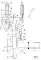
- FIG. 1 an inventive safety valve 1 according to an embodiment of the invention is shown.
- the safety valve 1 comprises a main body 24 with an inlet 2 and an outlet 3.
- the inlet 2 is connected to a line in which a liquid, in particular an aggressive medium, which for example has a temperature of 300 ° C, is transported.
- the inlet 2 is sealed by a closing element 4 of the safety valve 1, wherein a conical end piece 14 of the closing element 4 provides the seal.
- a pressure of a liquid transported in a line is too low to move the closing element 4 from the position shown.
- the elongated closing element 4 has, following the conical end piece 14, a cylindrical part 28 which may be hollow or solid. Subsequent to the cylindrical part 28, the closing element 4 is formed tapered, but two sliding portions 29 are provided, the outer diameter of which corresponds to that of the cylindrical portion 28. These sliding portions 29 are arranged between the cylindrical part 28 and the conical end piece 14 opposite end 15.
- the closing element 4 is held vertically movable in a seat 25.
- the seat 25 is in turn encompassed by the main body 24, in which the inlet 2 and the outlet 3 extend.
- the closing element 4 is surrounded by a T-piece 31 in the region of the end 15 opposite the conical end piece 14.
- an arm 5 is pivotally mounted about an axis 8, wherein a bolt 11 is provided for the pivotable mounting.
- the arm 5, which consists for example of steel, is in Essentially rigid and straight and formed at its other end to a spring element 6 about an axis 7 also pivotally mounted, in turn, a bolt 10 is provided for storage.
- the arm 5, which is in the in Fig. 1 shown situation can be made approximately at an angle of 30 ° to 75 ° to the closing element 4, approximately centered about a further axis 9 pivotally mounted, again for the storage of a bolt 12 is used.
- the arm 5 is not only pivotable, but because a slot 13 is provided, also relative to the axis 9 to this slidably. In the region of the slot 13, the arm 5 may be surface hardened, so that a high resistance to wear is given.
- the bolt 10, on which the arm 5 is mounted to connect the spring element 6 with the closing element 4, is part of an extension 21 of the spring element 6.
- the spring element 6 consists of a projection 21 connected to the longitudinal body 16, with a projecting End 20 passes through a recess 27 through the cover plate 26 and on the opposite side of the cover plate 26 comprises an upper spring holder 17, a lower spring holder 18 and a spring 19 located therebetween.
- the lower pen holder 18 is located in an in Fig. 1 not visible groove 23 of the cover plate 26, with a conical end 22.
- the longitudinal body 16 can by the lower spring holder 18 which rests as mentioned on the cover plate 26, slide, wherein the spring 19 is further tensioned.
- a maximum tilt angle of the spring element 6 is about 30 °. If a plurality of spring elements 6 are provided for a single closing element 4, which is advantageous in relation to a low overall height of the entire safety valve 1, the spring elements 6 are arranged so that they do not touch each other at the maximum tilt angle. With regard to a space-saving design, tilt angles of less than 10 ° are preferred.
- Fig. 3 It is shown how the inventive design of a safety valve 1 affects the given at the conical end piece 14 of the closing element 4 forces. While in a spring or a spring element with a linear characteristic curve, the characteristic shown in line A is obtained, the obtained with a safety valve 1 according to the invention power flow according to line B is variable. As in Fig. 3 it can be seen, at the beginning of a stroke of the closing element 4, a force is lower relative to a force of a spring with a linear characteristic. D. h. That the closing element 4 opens already at a lower force or at a lower pressure in a line.
- the force acting on the closing element 4 or the conical end piece 14 increases more with increasing stroke in comparison with a spring with a linear characteristic, so that the closing element 4 is slowed down after opening and further movement by the now increasing force, which is why it finally gently approaches an end position, in which the force can then decrease due to execution.
- a flutter is at least largely, ideally completely, avoided.
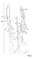
- Fig. 4 it is schematically illustrated how the lever ratios change due to the longitudinally displaceable arm 5 of the safety valve 1 according to the invention during an upward movement of the closing element 4.
- the sequence (from left to right) of a sealing position of the closure member 4 over a half-open position to a fully open position can by a combination of pivoting and longitudinal displacement of the arm 5 the forces F s acting during a movement of the closing element 4 are specifically taken into account by means of variable opposing forces F F.
Landscapes
- Engineering & Computer Science (AREA)
- General Engineering & Computer Science (AREA)
- Mechanical Engineering (AREA)
- Safety Valves (AREA)
Abstract
Description
Die Erfindung betrifft ein Sicherheitsventil mit einem Einlass und einem Auslass sowie einem Schließelement, das den Einlass abdichtet und sich bei Überdruck bewegt und dadurch einen Weg vom Einlass zum Auslass öffnet, wobei das Schließelement durch zumindest einen Arm mit zumindest einem Federelement verbunden ist, gegen dessen Kraft sich das Schließelement beim Öffnen bewegt.The invention relates to a safety valve having an inlet and an outlet and a closing element which seals the inlet and moves under pressure and thereby opens a path from the inlet to the outlet, wherein the closing element is connected by at least one arm with at least one spring element against which Force the closing element moves when opening.
Heute verwendete Sicherheitsventile sind einerseits hohen Temperaturen, beispielsweise in Dampfkraftwerken aktuell bis zu 560 °C, zukünftig bis zu 700 °C, sowie hohen Drücken bis zu 350 bar ausgesetzt und können andererseits z. B. in der Petrochemie mit äußerst aggressiven Medien wie Säuren in Kontakt kommen.Today used safety valves are on the one hand high temperatures, for example in steam power plants currently up to 560 ° C, in the future up to 700 ° C, and high pressures up to 350 bar exposed and on the other hand z. B. in petrochemicals with extremely aggressive media such as acids come into contact.
Bei vielen Sicherheitsventilen werden zum Halten bzw. Zurückbewegen eines Schließelementes eine oder mehrere Federn eingesetzt, wobei man bestrebt ist, die an sich empfindlichen Federn möglichst weit von dem oder den in einem Sicherheitsventil gegebenen Strömungswegen der gegebenenfalls aggressiven und teilweise auf hoher Temperatur befindlichen Medien zu positionieren, um die Federn zu schonen.In many safety valves, one or more springs are used for holding or moving back a closing element, wherein it is endeavored to position the sensitive to springs as far as possible or the given in a safety valve flow paths of the optionally aggressive and partly high-temperature media to protect the feathers.
Als Federn werden meist solche mit einer linearen Federkennlinie eingesetzt, was allerdings mehrere Nachteile mit sich bringt. Wirkt eine lineare Federkraft auf das Schließelement, so weist dieses beim Öffnen zuerst aufgrund der wirkenden linearen Federkraft ein wenig sensibles Ansprechverhalten auf, weshalb bei mit solchen Federn ausgestatteten Sicherheitsventilen eine unerwünscht hohe Druckdifferenz für das Öffnen des Schließelementes vorzusehen ist. Ein anderer Nachteil besteht darin, dass im Verlauf des Öffnens eine auf das Schließelement wirkende Federkraft zu gering ist, wenn sich dieses über längere Strecken bewegt und einer unter anderem durch einen Impuls eines strömenden Mediums auf das Schließelement wirkenden Kraft eine zu geringe Kraft entgegengesetzt wird. Dies resultiert darin, dass sich das Schließelement nach anfänglich verzögertem Öffnen mit hoher Geschwindigkeit bewegt und letztlich wenig gebremst an anderen Teilen des Sicherheitsventils anstoßen kann, worauf das Schließelement mehrmals um eine Gleichgewichtsposition pendelt, ehe es diese im besten Fall noch erreicht. Dieser Effekt wird in der Fachsprache als "Flattern" bezeichnet.As springs usually those with a linear spring characteristic are used, which, however, brings several disadvantages. Acts a linear spring force on the closing element, it has this when opening first due to the acting linear spring force a little sensitive response, which is why provided with such springs safety valves an undesirably high pressure difference for the opening of the closing element is provided. Another disadvantage is that in the course of opening a force acting on the closing element spring force is too low when it moves over longer distances and is opposed to a force acting, inter alia, by a pulse of a flowing medium on the closing element too low a force. This results in that the closing element after initial delayed opening moves at high speed and ultimately little braked abuts other parts of the safety valve, whereupon the closing element oscillates several times to an equilibrium position before it reaches them in the best case. This effect is referred to in the jargon as "fluttering".
Gemäß dem Stand der Technik bzw. bekannten Druckschriften ist schon auf verschiedene Arten versucht worden, eine Kraftübertragung eines Federelementes auf ein Schließelement variabel zu gestalten (
Aufgabe der Erfindung ist es, ein Sicherheitsventil der eingangs genannten Art so weiterzubilden, dass dieses bei einfachem Aufbau den am Schließelement während dessen Bewegung wirkenden Kräften ausreichend Rechnung trägt, sodass dieses bereits bei geringem Überdruck öffnet, ohne dass jedoch beim weiteren Öffnen ein Flattern auftritt.The object of the invention is to provide a safety valve of the type mentioned in such a way that this carries sufficient action on the closing element during its movement forces with a simple structure, so this already opens at low pressure, but without fluttering occurs during further opening.
Diese Aufgabe wird durch ein Sicherheitsventil der eingangs genannten Art gelöst, bei welchem ein Arm vorgesehen ist, der Schließelement und Federelement verbindet, wobei der Arm am Schließelement und am Federelement jeweils um eine Achse schwenkbar gelagert ist und um eine weitere, zwischen den genannten Achsen angeordnete Achse schwenkbar und gegenüber dieser längs verschiebbar ist.This object is achieved by a safety valve of the type mentioned, in which an arm is provided which connects closing element and spring element, wherein the arm is pivotally mounted on the closing element and the spring element about an axis and arranged around a further, between said axes Axis is pivotable and relative to this longitudinally displaceable.
Die mit der Erfindung erzielten Vorteile sind insbesondere darin zu sehen, dass durch die vorgesehene Ausbildung einer Verbindung des Schließelementes mit dem Federelement durch einen Arm, der nicht nur um am Schließelement bzw. Federelement befindliche Achsen schwenkbar gelagert ist, sondern auch um eine weitere zwischen den genannten Achsen angeordnete Achse schwenkbar und gegenüber dieser längs verschiebbar ist, quasi ein veränderlicher Hebelarm gegeben ist, was dazu führt, dass auf das Schließelement variable Kräfte wirken, die den am Schließelement insbesondere während dessen Bewegung positionsabhängig wirkenden Kräften optimal Rechnung tragen. Dadurch kann das Schließelement einerseits bereits bei geringen Überdrücken öffnen.The advantages achieved by the invention are to be seen in particular in that by the intended formation of a connection of the closing element with the spring element by an arm which is not only pivotally mounted to the closing element or spring element axes, but also to another between the axis arranged pivotally and longitudinally displaceable relative to this, quasi a variable lever arm is given, which leads to the closure element variable forces acting optimally take into account the forces acting positionally on the closing element in particular during its movement. As a result, on the one hand, the closing element can already open at low overpressures.
Andererseits steigt nach dem Öffnen des Schließelementes während dessen weiterer Bewegung eine auf das Schließelement wirkende Kraft variabel an, sodass ein Flattern des Schließelementes im Wesentlichen vermieden ist.On the other hand, after opening the closing element during its further movement, a force acting on the closing element increases variably, so that fluttering of the closing element is substantially avoided.
Der Arm kann auf beliebige Weise am Schließelement bzw. Federelement um die vorgesehenen Achsen schwenkbar gelagert sein. Um eine möglichst einfache Ausbildung des Sicherheitsventils zu erreichen, ist es jedoch zweckmäßig, dass der Arm mittels Bolzen am Schließelement und am Federelement um die Achsen schwenkbar gelagert ist.The arm can be mounted in any manner on the closing element or spring element about the provided axes pivotally. In order to achieve the simplest possible design of the safety valve, it is expedient, however, for the arm to be pivotably mounted about the axes by means of bolts on the closing element and on the spring element.
Eine Längsverschiebbarkeit des Armes gleichzeitig mit einer Schwenkbarkeit desselben um eine weitere Achse kann in besonders einfacher Weise realisiert werden, wenn der Arm ein Langloch aufweist, in welches ein weiterer Bolzen eingreift, auf dem der Arm gelagert ist.A longitudinal displacement of the arm at the same time with a pivoting about a further axis can be realized in a particularly simple manner when the arm has a slot into which engages another bolt on which the arm is mounted.
Obwohl auch andere Ausführungsvarianten möglich sind, ist es zweckmäßig, dass die Achsen etwa im Bereich von Enden des Armes angeordnet sind, damit eine kompakte bzw. platzsparende Bauweise gegeben ist.Although other embodiments are possible, it is appropriate that the axes are arranged approximately in the region of ends of the arm, so that a compact or space-saving design is given.
Wenngleich sich das erfindungsgemäße Konzept auf verschiedene Sicherheitsventile anwenden lässt, erweist es sich doch als besonders zweckmäßig, wenn das Schließelement länglich und mit einem vorzugsweise konischen Endstück ausgebildet ist, welches den Einlass abdichtet. Der Arm ist dann besonders bevorzugt an dem dem konischen Endstück gegenüberliegenden Ende des Schließelementes gelagert. Anstelle eines konischen Endstückes kann grundsätzlich auch ein eben ausgebildetes Endstück vorgesehen sein.Although the inventive concept can be applied to various safety valves, it proves to be particularly useful if the closing element is elongated and formed with a preferably conical end piece which seals the inlet. The arm is then particularly preferably mounted on the end opposite the conical end of the closing element. Instead of a conical end piece can basically be provided a newly formed end piece.
Auch das Federelement kann auf unterschiedliche Arten ausgebildet sein, sofern das Schließelement mit einer gewünschten Federkraft beaufschlagt wird. Günstig ist es jedoch, wenn das Federelement einen Längskörper mit einem oberen Federhalter und einem unteren Federhalter sowie einer zwischen oberem Federhalter und unterem Federhalter gehaltenen Feder umfasst, wobei der Längskörper den unteren Federhalter durchsetzt und durch diesen gleiten kann und im Bereich eines über den unteren Federhalter vorspringenden Endes oder eines damit in Verbindung stehenden Fortsatzes mit dem Arm verbunden ist. Dabei ist der untere Federhalter vorzugsweise mit einem konischen Ende ausgebildet. Dies ermöglicht es, dass das konische Ende des unteren Federhalters in einer etwa halbrunden Nut aufliegen kann, wodurch auf besonders einfache Weise die erforderliche Schwenkbarkeit des Federelementes realisiert werden kann, wenn sich das Schließelement und damit der Arm bewegt.Also, the spring element may be formed in different ways, provided that the closing element is acted upon by a desired spring force. It is favorable, however, if the spring element comprises a longitudinal body with an upper spring holder and a lower spring holder and a spring held between the upper spring holder and lower spring, wherein the longitudinal body passes through the lower spring holder and can slide through this and in the region of the lower spring holder projecting end or an associated extension is connected to the arm. In this case, the lower spring holder is preferably with a formed conical end. This makes it possible that the conical end of the lower spring holder can rest in an approximately semicircular groove, whereby the required pivotability of the spring element can be realized in a particularly simple manner when the closing element and thus the arm moves.
Für die entsprechende Lagerung des konischen Endes in der halbrunden Nut oder ganz allgemein auf einer Auflagefläche erweist es sich als zweckmäßig, dass ein Grundkörper vorgesehen ist, in welchem das Schließelement angeordnet ist und der Grundkörper eine Deckplatte oder eine andere zweckdienlich gestaltete Aufnahme mit einer Ausnehmung aufweist, durch welche das vorspringende Ende des Längskörpers verläuft. Dadurch ist auf einfache Weise eine Auflagefläche für das Federelement gegeben und kann sich der Längskörper im Wesentlichen reibungsfrei bewegen und das Federelement je nach Bedarf kippen. Wenngleich auch andere Ausbildungen möglich sind, steht in einer bevorzugten Ausführungsvariante eines erfindungsgemäßen Sicherheitsventils das Federelement bei einer dichtenden Position des Schließelementes im Wesentlichen vertikal und kippt erst bei Bewegung des Schließelementes bzw. bei Bewegung des Armes.For the corresponding storage of the conical end in the semicircular groove or generally on a support surface, it proves to be advantageous that a base body is provided, in which the closing element is arranged and the base body has a cover plate or another suitably shaped receptacle with a recess through which the projecting end of the longitudinal body passes. As a result, a bearing surface for the spring element is given in a simple manner and the longitudinal body can move substantially without friction and tilt the spring element as needed. Although other embodiments are possible, is in a preferred embodiment of a safety valve according to the invention, the spring element at a sealing position of the closing element substantially vertically and tilts only upon movement of the closing element or during movement of the arm.
Das Schließelement kann insbesondere vertikal beweglich ausgeführt sein, wenngleich das Schließelement auch in anderer Weise bewegbar sein kann.The closing element may in particular be designed to be vertically movable, although the closing element may also be movable in another way.
Des Weiteren können bei einem erfindungsgemäßen Sicherheitsventil mehrere, vorzugsweise zwei bis vier, Federelemente vorgesehen sein. Dies erweist sich insbesondere als günstig, wenn eine geringe Bauhöhe des Sicherheitsventils gewünscht ist. Um eine möglichst gleichmäßige Kräfteverteilung am Schließelement zu erreichen, sind die einzelnen Federelemente dabei in Draufsicht auf das Sicherheitsventil vorzugsweise rotationssymmetrisch um das Schließelement angeordnet.Furthermore, in a safety valve according to the invention several, preferably two to four, spring elements may be provided. This proves to be particularly favorable when a low height of the safety valve is desired. In order to achieve a uniform distribution of forces on the closing element, the individual spring elements are arranged in a plan view of the safety valve preferably rotationally symmetrical about the closing element.
Weitere Merkmale, Vorteile und Wirkungen der Erfindung ergeben sich aus dem nachfolgend dargestellten Ausführungsbeispiel, anhand dessen die Erfindung noch näher erläutert ist. In den anliegenden Zeichnungen, auf die dabei Bezug genommen ist, zeigen:
-
Fig. 1 einen Querschnitt eines erfindungsgemäßen Sicherheitsventils; -
Fig. 2 Teile eines erfindungsgemäßen Sicherheitsventils im geschlossenen Zustand (links) und im teilweise geöffneten Zustand (rechts); -
Fig. 3 ein Diagramm betreffend wirkende Kräfte am dichtenden Ende eines Schließelementes; -
Fig. 4 eine schematische Darstellung betreffend Kräfteverhältnisse bei einem erfindungsgemäßen Sicherheitsventil.
-
Fig. 1 a cross section of a safety valve according to the invention; -
Fig. 2 Parts of a safety valve according to the invention in the closed state (left) and in the partially open state (right); -
Fig. 3 a diagram relating to acting forces at the sealing end of a closing element; -
Fig. 4 a schematic representation of force relationships in a safety valve according to the invention.
In
Das länglich ausgebildete Schließelement 4 weist im Anschluss an das konische Endstück 14 einen zylindrischen Teil 28 auf, der hohl oder massiv ausgebildet sein kann. Im Anschluss an den zylindrischen Teil 28 ist das Schließelement 4 verjüngt ausgebildet, wobei jedoch zwei Gleitbereiche 29 vorgesehen sind, deren Außendurchmesser jenem des zylindrischen Teils 28 entspricht. Diese Gleitbereiche 29 sind zwischen dem zylindrischen Teil 28 und einem dem konischen Endstück 14 gegenüberliegenden Ende 15 angeordnet.The
Das Schließelement 4 ist in einem Sitz 25 vertikal beweglich gehalten. Der Sitz 25 wird seinerseits vom Grundkörper 24 umfasst, in welchem der Einlass 2 und der Auslass 3 verlaufen. Um ein oberes Ende des Grundkörpers 24 herum ist ein Außenteil 30 angeordnet, der seitliche Durchbrechungen 32 aufweist und eine Deckplatte 26 trägt.The
Das Schließelement 4 ist im Bereich des dem konischen Endstück 14 gegenüberliegenden Endes 15 von einem T-Stück 31 umgeben. An diesem T-Stück 31 ist ein Arm 5 um eine Achse 8 schwenkbar gelagert, wobei für die schwenkbare Lagerung ein Bolzen 11 vorgesehen ist. Der Arm 5, der beispielsweise aus Stahl besteht, ist im Wesentlichen starr sowie gerade ausgebildet und an seinem anderen Ende an einem Federelement 6 um eine Achse 7 ebenfalls schwenkbar gelagert, wobei für die Lagerung wiederum ein Bolzen 10 vorgesehen ist. Des Weiteren ist der Arm 5, der in der in
Der Bolzen 10, auf welchem der Arm 5 gelagert ist, um das Federelement 6 mit dem Schließelement 4 zu verbinden, ist Teil eines Fortsatzes 21 des Federelementes 6. Das Federelement 6 besteht aus einem mit dem Fortsatz 21 verbundenen Längskörper 16, der mit einem vorspringenden Ende 20 durch eine Ausnehmung 27 hindurch die Deckplatte 26 durchsetzt und auf der gegenüberliegenden Seite der Deckplatte 26 einen oberen Federhalter 17, einen unteren Federhalter 18 und eine dazwischen befindliche Feder 19 umfasst. Der untere Federhalter 18 liegt in einer in
Bei der in
In
In
In
Claims (13)
Applications Claiming Priority (1)
| Application Number | Priority Date | Filing Date | Title |
|---|---|---|---|
| AT0097208A AT506990B1 (en) | 2008-06-18 | 2008-06-18 | SAFETY VALVE |
Publications (3)
| Publication Number | Publication Date |
|---|---|
| EP2136115A2 true EP2136115A2 (en) | 2009-12-23 |
| EP2136115A3 EP2136115A3 (en) | 2010-09-29 |
| EP2136115B1 EP2136115B1 (en) | 2011-12-14 |
Family
ID=40974598
Family Applications (1)
| Application Number | Title | Priority Date | Filing Date |
|---|---|---|---|
| EP20090162691 Not-in-force EP2136115B1 (en) | 2008-06-18 | 2009-06-15 | Safety valve |
Country Status (3)
| Country | Link |
|---|---|
| US (1) | US8479764B2 (en) |
| EP (1) | EP2136115B1 (en) |
| AT (2) | AT506990B1 (en) |
Citations (7)
| Publication number | Priority date | Publication date | Assignee | Title |
|---|---|---|---|---|
| US58962A (en) | 1866-10-16 | Improvement in steam safety-valves | ||
| US2973777A (en) | 1959-03-20 | 1961-03-07 | Cameron Iron Works Inc | Pressure relief valve |
| SU723260A1 (en) | 1977-12-19 | 1980-03-25 | Предприятие П/Я А-7899 | Safety valve |
| US4201242A (en) | 1978-06-13 | 1980-05-06 | Cameron Iron Works, Inc. | Pressure relief valve |
| JPH08121626A (en) | 1994-10-18 | 1996-05-17 | Toshiba Corp | Main steam relief safety valve |
| US5909748A (en) | 1998-05-26 | 1999-06-08 | Lacroix; Barry | Pressure relief valve |
| DE19860578A1 (en) | 1998-12-29 | 2000-07-06 | Asea Brown Boveri | Spring loaded safety valve |
Family Cites Families (6)
| Publication number | Priority date | Publication date | Assignee | Title |
|---|---|---|---|---|
| DE5369C (en) * | A. SCHJIID in Zürich | Safety valve | ||
| US1408603A (en) * | 1917-09-17 | 1922-03-07 | Luftfahrzeugbau Schutte Lanz | Deflating and safety valve for gas-filled balloons |
| DE1163100B (en) | 1958-11-03 | 1964-02-13 | Gerdts Gustav F Kg | Shut-off valve, especially filling and draining valve for tank wagons |
| US3229713A (en) * | 1962-11-06 | 1966-01-18 | Charles W Wiegand | Pressure control valve |
| FR1468643A (en) | 1963-11-29 | 1967-02-10 | Further development of direct-acting pressure regulators, particularly for gaseous fluids under medium and high pressure | |
| SU1046565A1 (en) * | 1981-12-21 | 1983-10-07 | Предприятие П/Я А-7899 | Safety valve |
-
2008
- 2008-06-18 AT AT0097208A patent/AT506990B1/en not_active IP Right Cessation
-
2009
- 2009-06-15 AT AT09162691T patent/ATE537394T1/en active
- 2009-06-15 EP EP20090162691 patent/EP2136115B1/en not_active Not-in-force
- 2009-06-17 US US12/486,286 patent/US8479764B2/en not_active Expired - Fee Related
Patent Citations (7)
| Publication number | Priority date | Publication date | Assignee | Title |
|---|---|---|---|---|
| US58962A (en) | 1866-10-16 | Improvement in steam safety-valves | ||
| US2973777A (en) | 1959-03-20 | 1961-03-07 | Cameron Iron Works Inc | Pressure relief valve |
| SU723260A1 (en) | 1977-12-19 | 1980-03-25 | Предприятие П/Я А-7899 | Safety valve |
| US4201242A (en) | 1978-06-13 | 1980-05-06 | Cameron Iron Works, Inc. | Pressure relief valve |
| JPH08121626A (en) | 1994-10-18 | 1996-05-17 | Toshiba Corp | Main steam relief safety valve |
| US5909748A (en) | 1998-05-26 | 1999-06-08 | Lacroix; Barry | Pressure relief valve |
| DE19860578A1 (en) | 1998-12-29 | 2000-07-06 | Asea Brown Boveri | Spring loaded safety valve |
Also Published As
| Publication number | Publication date |
|---|---|
| US20090320938A1 (en) | 2009-12-31 |
| EP2136115B1 (en) | 2011-12-14 |
| US8479764B2 (en) | 2013-07-09 |
| AT506990A1 (en) | 2010-01-15 |
| ATE537394T1 (en) | 2011-12-15 |
| EP2136115A3 (en) | 2010-09-29 |
| AT506990B1 (en) | 2010-11-15 |
Similar Documents
| Publication | Publication Date | Title |
|---|---|---|
| DE102017007236B4 (en) | Throttle valve with proportional overflow | |
| EP1978304B1 (en) | Blocking system for large sections of piping with a swinging flap | |
| EP1818491A2 (en) | Fitting for a cabinet lid | |
| DE2449857C3 (en) | Check valve for pipelines | |
| EP2784406A1 (en) | Volume flow regulator | |
| EP0790381A2 (en) | Door closer with controlled closing movement | |
| CH700776B1 (en) | Slide valves, in particular leading to the closing of a media line. | |
| EP1936151A2 (en) | Method for manufacturing a device for controlling the throughflow of a gaseous or liquid medium | |
| DE3723120A1 (en) | AUTOMATICALLY CONTROLLED SERVO VALVE WITH QUICK OPENING | |
| EP2136115B1 (en) | Safety valve | |
| DE1959547B2 (en) | Valve, especially thermostatic expansion valve for refrigeration systems | |
| EP2940396B1 (en) | Device for regulating a through-flow of a duct with a fluid | |
| EP1637783B1 (en) | Valve combination for a steam turbine with a fast closing valve and a regulating valve | |
| CH622326A5 (en) | ||
| DE202016001236U1 (en) | manual valve | |
| DE1927413B2 (en) | Control device for air supply in air conditioning systems | |
| DE102010041704A1 (en) | Regulating valve for controlling flow volume inside pipeline, is arranged in pipeline rotatable around rotational axis and corresponding to its rotational position decontrols flow cross-section inside pipeline | |
| DE10348436A1 (en) | Linkage assembly for door closer, has lever with one end connected to one end of another lever and another end carrying bearing support, where former lever includes end stop to which one end of L-shaped hook is connected | |
| DE2213587C3 (en) | throttle | |
| DE3310747C2 (en) | ||
| DE2308333A1 (en) | CONTROL VALVE | |
| EP2546717B1 (en) | Pressure regulating valve for a cryotank | |
| DE2359470C3 (en) | Pressure reducing valve | |
| DE102004024525B4 (en) | Gas pipeline shut-off device, has shut-off valve, which pivots swivel axis between opening and closing positions, in which valve together with swivel axis is outside gas flow profile of housing in opening position | |
| DE2603242C3 (en) | Folding louvre for closing a delivery line for hot gases |
Legal Events
| Date | Code | Title | Description |
|---|---|---|---|
| PUAI | Public reference made under article 153(3) epc to a published international application that has entered the european phase |
Free format text: ORIGINAL CODE: 0009012 |
|
| AK | Designated contracting states |
Kind code of ref document: A2 Designated state(s): AT BE BG CH CY CZ DE DK EE ES FI FR GB GR HR HU IE IS IT LI LT LU LV MC MK MT NL NO PL PT RO SE SI SK TR |
|
| PUAL | Search report despatched |
Free format text: ORIGINAL CODE: 0009013 |
|
| AK | Designated contracting states |
Kind code of ref document: A3 Designated state(s): AT BE BG CH CY CZ DE DK EE ES FI FR GB GR HR HU IE IS IT LI LT LU LV MC MK MT NL NO PL PT RO SE SI SK TR |
|
| AX | Request for extension of the european patent |
Extension state: AL BA RS |
|
| 17P | Request for examination filed |
Effective date: 20110329 |
|
| RIC1 | Information provided on ipc code assigned before grant |
Ipc: F16K 17/04 20060101AFI20110509BHEP Ipc: F16K 17/06 20060101ALI20110509BHEP |
|
| GRAP | Despatch of communication of intention to grant a patent |
Free format text: ORIGINAL CODE: EPIDOSNIGR1 |
|
| GRAS | Grant fee paid |
Free format text: ORIGINAL CODE: EPIDOSNIGR3 |
|
| GRAA | (expected) grant |
Free format text: ORIGINAL CODE: 0009210 |
|
| AK | Designated contracting states |
Kind code of ref document: B1 Designated state(s): AT BE BG CH CY CZ DE DK EE ES FI FR GB GR HR HU IE IS IT LI LT LU LV MC MK MT NL NO PL PT RO SE SI SK TR |
|
| REG | Reference to a national code |
Ref country code: GB Ref legal event code: FG4D Free format text: NOT ENGLISH |
|
| REG | Reference to a national code |
Ref country code: CH Ref legal event code: EP |
|
| REG | Reference to a national code |
Ref country code: IE Ref legal event code: FG4D |
|
| REG | Reference to a national code |
Ref country code: DE Ref legal event code: R082 Ref document number: 502009002173 Country of ref document: DE Representative=s name: ZEUNER SUMMERER STUETZ PATENT- UND RECHTSANWAE, DE Ref country code: DE Ref legal event code: R082 Ref document number: 502009002173 Country of ref document: DE Representative=s name: ZEUNER SUMMERER STUETZ PATENT- UND RECHTSANWAL, DE |
|
| REG | Reference to a national code |
Ref country code: NL Ref legal event code: T3 |
|
| REG | Reference to a national code |
Ref country code: DE Ref legal event code: R096 Ref document number: 502009002173 Country of ref document: DE Effective date: 20120315 |
|
| PG25 | Lapsed in a contracting state [announced via postgrant information from national office to epo] |
Ref country code: LT Free format text: LAPSE BECAUSE OF FAILURE TO SUBMIT A TRANSLATION OF THE DESCRIPTION OR TO PAY THE FEE WITHIN THE PRESCRIBED TIME-LIMIT Effective date: 20111214 Ref country code: NO Free format text: LAPSE BECAUSE OF FAILURE TO SUBMIT A TRANSLATION OF THE DESCRIPTION OR TO PAY THE FEE WITHIN THE PRESCRIBED TIME-LIMIT Effective date: 20120314 |
|
| LTIE | Lt: invalidation of european patent or patent extension |
Effective date: 20111214 |
|
| PG25 | Lapsed in a contracting state [announced via postgrant information from national office to epo] |
Ref country code: HR Free format text: LAPSE BECAUSE OF FAILURE TO SUBMIT A TRANSLATION OF THE DESCRIPTION OR TO PAY THE FEE WITHIN THE PRESCRIBED TIME-LIMIT Effective date: 20111214 Ref country code: SE Free format text: LAPSE BECAUSE OF FAILURE TO SUBMIT A TRANSLATION OF THE DESCRIPTION OR TO PAY THE FEE WITHIN THE PRESCRIBED TIME-LIMIT Effective date: 20111214 Ref country code: GR Free format text: LAPSE BECAUSE OF FAILURE TO SUBMIT A TRANSLATION OF THE DESCRIPTION OR TO PAY THE FEE WITHIN THE PRESCRIBED TIME-LIMIT Effective date: 20120315 Ref country code: LV Free format text: LAPSE BECAUSE OF FAILURE TO SUBMIT A TRANSLATION OF THE DESCRIPTION OR TO PAY THE FEE WITHIN THE PRESCRIBED TIME-LIMIT Effective date: 20111214 Ref country code: SI Free format text: LAPSE BECAUSE OF FAILURE TO SUBMIT A TRANSLATION OF THE DESCRIPTION OR TO PAY THE FEE WITHIN THE PRESCRIBED TIME-LIMIT Effective date: 20111214 |
|
| PG25 | Lapsed in a contracting state [announced via postgrant information from national office to epo] |
Ref country code: CY Free format text: LAPSE BECAUSE OF FAILURE TO SUBMIT A TRANSLATION OF THE DESCRIPTION OR TO PAY THE FEE WITHIN THE PRESCRIBED TIME-LIMIT Effective date: 20111214 |
|
| REG | Reference to a national code |
Ref country code: IE Ref legal event code: FD4D |
|
| PG25 | Lapsed in a contracting state [announced via postgrant information from national office to epo] |
Ref country code: SK Free format text: LAPSE BECAUSE OF FAILURE TO SUBMIT A TRANSLATION OF THE DESCRIPTION OR TO PAY THE FEE WITHIN THE PRESCRIBED TIME-LIMIT Effective date: 20111214 Ref country code: IS Free format text: LAPSE BECAUSE OF FAILURE TO SUBMIT A TRANSLATION OF THE DESCRIPTION OR TO PAY THE FEE WITHIN THE PRESCRIBED TIME-LIMIT Effective date: 20120414 Ref country code: EE Free format text: LAPSE BECAUSE OF FAILURE TO SUBMIT A TRANSLATION OF THE DESCRIPTION OR TO PAY THE FEE WITHIN THE PRESCRIBED TIME-LIMIT Effective date: 20111214 Ref country code: IE Free format text: LAPSE BECAUSE OF FAILURE TO SUBMIT A TRANSLATION OF THE DESCRIPTION OR TO PAY THE FEE WITHIN THE PRESCRIBED TIME-LIMIT Effective date: 20111214 Ref country code: BG Free format text: LAPSE BECAUSE OF FAILURE TO SUBMIT A TRANSLATION OF THE DESCRIPTION OR TO PAY THE FEE WITHIN THE PRESCRIBED TIME-LIMIT Effective date: 20120314 Ref country code: CZ Free format text: LAPSE BECAUSE OF FAILURE TO SUBMIT A TRANSLATION OF THE DESCRIPTION OR TO PAY THE FEE WITHIN THE PRESCRIBED TIME-LIMIT Effective date: 20111214 |
|
| PG25 | Lapsed in a contracting state [announced via postgrant information from national office to epo] |
Ref country code: RO Free format text: LAPSE BECAUSE OF FAILURE TO SUBMIT A TRANSLATION OF THE DESCRIPTION OR TO PAY THE FEE WITHIN THE PRESCRIBED TIME-LIMIT Effective date: 20111214 Ref country code: PL Free format text: LAPSE BECAUSE OF FAILURE TO SUBMIT A TRANSLATION OF THE DESCRIPTION OR TO PAY THE FEE WITHIN THE PRESCRIBED TIME-LIMIT Effective date: 20111214 Ref country code: PT Free format text: LAPSE BECAUSE OF FAILURE TO SUBMIT A TRANSLATION OF THE DESCRIPTION OR TO PAY THE FEE WITHIN THE PRESCRIBED TIME-LIMIT Effective date: 20120416 |
|
| PLBE | No opposition filed within time limit |
Free format text: ORIGINAL CODE: 0009261 |
|
| STAA | Information on the status of an ep patent application or granted ep patent |
Free format text: STATUS: NO OPPOSITION FILED WITHIN TIME LIMIT |
|
| PG25 | Lapsed in a contracting state [announced via postgrant information from national office to epo] |
Ref country code: DK Free format text: LAPSE BECAUSE OF FAILURE TO SUBMIT A TRANSLATION OF THE DESCRIPTION OR TO PAY THE FEE WITHIN THE PRESCRIBED TIME-LIMIT Effective date: 20111214 |
|
| 26N | No opposition filed |
Effective date: 20120917 |
|
| BERE | Be: lapsed |
Owner name: BHDT GMBH Effective date: 20120630 |
|
| REG | Reference to a national code |
Ref country code: DE Ref legal event code: R097 Ref document number: 502009002173 Country of ref document: DE Effective date: 20120917 |
|
| PG25 | Lapsed in a contracting state [announced via postgrant information from national office to epo] |
Ref country code: MC Free format text: LAPSE BECAUSE OF NON-PAYMENT OF DUE FEES Effective date: 20120630 |
|
| PG25 | Lapsed in a contracting state [announced via postgrant information from national office to epo] |
Ref country code: MK Free format text: LAPSE BECAUSE OF FAILURE TO SUBMIT A TRANSLATION OF THE DESCRIPTION OR TO PAY THE FEE WITHIN THE PRESCRIBED TIME-LIMIT Effective date: 20111214 |
|
| PG25 | Lapsed in a contracting state [announced via postgrant information from national office to epo] |
Ref country code: ES Free format text: LAPSE BECAUSE OF FAILURE TO SUBMIT A TRANSLATION OF THE DESCRIPTION OR TO PAY THE FEE WITHIN THE PRESCRIBED TIME-LIMIT Effective date: 20120325 Ref country code: BE Free format text: LAPSE BECAUSE OF NON-PAYMENT OF DUE FEES Effective date: 20120630 |
|
| PG25 | Lapsed in a contracting state [announced via postgrant information from national office to epo] |
Ref country code: FI Free format text: LAPSE BECAUSE OF FAILURE TO SUBMIT A TRANSLATION OF THE DESCRIPTION OR TO PAY THE FEE WITHIN THE PRESCRIBED TIME-LIMIT Effective date: 20111214 |
|
| PG25 | Lapsed in a contracting state [announced via postgrant information from national office to epo] |
Ref country code: MT Free format text: LAPSE BECAUSE OF FAILURE TO SUBMIT A TRANSLATION OF THE DESCRIPTION OR TO PAY THE FEE WITHIN THE PRESCRIBED TIME-LIMIT Effective date: 20111214 |
|
| REG | Reference to a national code |
Ref country code: CH Ref legal event code: PL |
|
| PG25 | Lapsed in a contracting state [announced via postgrant information from national office to epo] |
Ref country code: CH Free format text: LAPSE BECAUSE OF NON-PAYMENT OF DUE FEES Effective date: 20130630 Ref country code: TR Free format text: LAPSE BECAUSE OF FAILURE TO SUBMIT A TRANSLATION OF THE DESCRIPTION OR TO PAY THE FEE WITHIN THE PRESCRIBED TIME-LIMIT Effective date: 20111214 Ref country code: LI Free format text: LAPSE BECAUSE OF NON-PAYMENT OF DUE FEES Effective date: 20130630 |
|
| PG25 | Lapsed in a contracting state [announced via postgrant information from national office to epo] |
Ref country code: LU Free format text: LAPSE BECAUSE OF NON-PAYMENT OF DUE FEES Effective date: 20120615 |
|
| PG25 | Lapsed in a contracting state [announced via postgrant information from national office to epo] |
Ref country code: HU Free format text: LAPSE BECAUSE OF FAILURE TO SUBMIT A TRANSLATION OF THE DESCRIPTION OR TO PAY THE FEE WITHIN THE PRESCRIBED TIME-LIMIT Effective date: 20090615 |
|
| REG | Reference to a national code |
Ref country code: FR Ref legal event code: PLFP Year of fee payment: 7 |
|
| PGFP | Annual fee paid to national office [announced via postgrant information from national office to epo] |
Ref country code: DE Payment date: 20150619 Year of fee payment: 7 Ref country code: GB Payment date: 20150618 Year of fee payment: 7 |
|
| PGFP | Annual fee paid to national office [announced via postgrant information from national office to epo] |
Ref country code: IT Payment date: 20150622 Year of fee payment: 7 Ref country code: NL Payment date: 20150618 Year of fee payment: 7 Ref country code: AT Payment date: 20150527 Year of fee payment: 7 Ref country code: FR Payment date: 20150619 Year of fee payment: 7 |
|
| REG | Reference to a national code |
Ref country code: DE Ref legal event code: R119 Ref document number: 502009002173 Country of ref document: DE |
|
| REG | Reference to a national code |
Ref country code: NL Ref legal event code: MM Effective date: 20160701 |
|
| REG | Reference to a national code |
Ref country code: AT Ref legal event code: MM01 Ref document number: 537394 Country of ref document: AT Kind code of ref document: T Effective date: 20160615 |
|
| GBPC | Gb: european patent ceased through non-payment of renewal fee |
Effective date: 20160615 |
|
| REG | Reference to a national code |
Ref country code: FR Ref legal event code: ST Effective date: 20170228 |
|
| PG25 | Lapsed in a contracting state [announced via postgrant information from national office to epo] |
Ref country code: DE Free format text: LAPSE BECAUSE OF NON-PAYMENT OF DUE FEES Effective date: 20170103 Ref country code: FR Free format text: LAPSE BECAUSE OF NON-PAYMENT OF DUE FEES Effective date: 20160630 |
|
| PG25 | Lapsed in a contracting state [announced via postgrant information from national office to epo] |
Ref country code: GB Free format text: LAPSE BECAUSE OF NON-PAYMENT OF DUE FEES Effective date: 20160615 Ref country code: AT Free format text: LAPSE BECAUSE OF NON-PAYMENT OF DUE FEES Effective date: 20160615 Ref country code: NL Free format text: LAPSE BECAUSE OF NON-PAYMENT OF DUE FEES Effective date: 20160701 |
|
| PG25 | Lapsed in a contracting state [announced via postgrant information from national office to epo] |
Ref country code: IT Free format text: LAPSE BECAUSE OF NON-PAYMENT OF DUE FEES Effective date: 20160615 |